EP2497970A1 - Buchse - Google Patents
Buchse Download PDFInfo
- Publication number
- EP2497970A1 EP2497970A1 EP10828273A EP10828273A EP2497970A1 EP 2497970 A1 EP2497970 A1 EP 2497970A1 EP 10828273 A EP10828273 A EP 10828273A EP 10828273 A EP10828273 A EP 10828273A EP 2497970 A1 EP2497970 A1 EP 2497970A1
- Authority
- EP
- European Patent Office
- Prior art keywords
- joint pin
- bush
- bearing
- inner cylinder
- axial direction
- Prior art date
- Legal status (The legal status is an assumption and is not a legal conclusion. Google has not performed a legal analysis and makes no representation as to the accuracy of the status listed.)
- Withdrawn
Links
Images


Classifications
-
- F—MECHANICAL ENGINEERING; LIGHTING; HEATING; WEAPONS; BLASTING
- F16—ENGINEERING ELEMENTS AND UNITS; GENERAL MEASURES FOR PRODUCING AND MAINTAINING EFFECTIVE FUNCTIONING OF MACHINES OR INSTALLATIONS; THERMAL INSULATION IN GENERAL
- F16F—SPRINGS; SHOCK-ABSORBERS; MEANS FOR DAMPING VIBRATION
- F16F1/00—Springs
- F16F1/36—Springs made of rubber or other material having high internal friction, e.g. thermoplastic elastomers
- F16F1/38—Springs made of rubber or other material having high internal friction, e.g. thermoplastic elastomers with a sleeve of elastic material between a rigid outer sleeve and a rigid inner sleeve or pin, i.e. bushing-type
- F16F1/3842—Method of assembly, production or treatment; Mounting thereof
-
- B—PERFORMING OPERATIONS; TRANSPORTING
- B60—VEHICLES IN GENERAL
- B60G—VEHICLE SUSPENSION ARRANGEMENTS
- B60G11/00—Resilient suspensions characterised by arrangement, location or kind of springs
- B60G11/26—Resilient suspensions characterised by arrangement, location or kind of springs having fluid springs only, e.g. hydropneumatic springs
- B60G11/27—Resilient suspensions characterised by arrangement, location or kind of springs having fluid springs only, e.g. hydropneumatic springs wherein the fluid is a gas
-
- B—PERFORMING OPERATIONS; TRANSPORTING
- B60—VEHICLES IN GENERAL
- B60G—VEHICLE SUSPENSION ARRANGEMENTS
- B60G7/00—Pivoted suspension arms; Accessories thereof
- B60G7/005—Ball joints
-
- B—PERFORMING OPERATIONS; TRANSPORTING
- B60—VEHICLES IN GENERAL
- B60G—VEHICLE SUSPENSION ARRANGEMENTS
- B60G2202/00—Indexing codes relating to the type of spring, damper or actuator
- B60G2202/10—Type of spring
- B60G2202/15—Fluid spring
- B60G2202/152—Pneumatic spring
- B60G2202/1524—Pneumatic spring with two air springs per wheel, arranged before and after the wheel axis
-
- B—PERFORMING OPERATIONS; TRANSPORTING
- B60—VEHICLES IN GENERAL
- B60G—VEHICLE SUSPENSION ARRANGEMENTS
- B60G2204/00—Indexing codes related to suspensions per se or to auxiliary parts
- B60G2204/40—Auxiliary suspension parts; Adjustment of suspensions
- B60G2204/41—Elastic mounts, e.g. bushings
-
- B—PERFORMING OPERATIONS; TRANSPORTING
- B60—VEHICLES IN GENERAL
- B60G—VEHICLE SUSPENSION ARRANGEMENTS
- B60G2204/00—Indexing codes related to suspensions per se or to auxiliary parts
- B60G2204/40—Auxiliary suspension parts; Adjustment of suspensions
- B60G2204/416—Ball or spherical joints
-
- B—PERFORMING OPERATIONS; TRANSPORTING
- B60—VEHICLES IN GENERAL
- B60G—VEHICLE SUSPENSION ARRANGEMENTS
- B60G2206/00—Indexing codes related to the manufacturing of suspensions: constructional features, the materials used, procedures or tools
- B60G2206/01—Constructional features of suspension elements, e.g. arms, dampers, springs
- B60G2206/10—Constructional features of arms
- B60G2206/11—Constructional features of arms the arm being a radius or track or torque or steering rod or stabiliser end link
Definitions
- the present invention relates to a bush provided between one member and the other member to absorb impact and vibrations transmitted between the members.
- a vehicle such as automobile, truck, and bus is provided with a suspension device between a vehicle body (one member) and an axle (the other member).
- the suspension device has a spring member absorbing impact and vibrations, and a damping member (absorbing member) damping vibrations of the spring member.
- a spring member a coil spring, an air spring, or the like is used.
- a damping member a hydraulic damper or the like is used.
- a suspension device of a truck or the like may include a torque rod in addition to the spring member and the damping member. On both end sides of the torque rod, torque rod bushes (bushes) are mounted.
- Each torque rod bush allows the axle to be relatively moved with respect to the bodywork within a predetermined range, absorbs propagation of impact vibrations inputted from a road surface to the bodywork and, in turn, improves the riding comfort and stability in handling, for example.
- technologies described in Patent Documents 1 and 2 have been known.
- An impact-absorbing joint (bush) described in Patent Document 1 includes an outer cylinder and an inner cylinder that are made of a steel material, and a cushion material (rubber) is provided between the outer cylinder and the inner cylinder by vulcanization bonding or the like.
- a cushion material rubber
- a narrow-diameter portion projecting inward in a radial direction is provided in a center portion in an axial direction of the inner cylinder.
- paired bearing members are provided on the inside in the radial direction of the narrow-diameter portion. The bearing members are mounted from both sides in the axial direction of the inner cylinder and each supported by a step portion of the narrow-diameter portion.
- each bearing member On the inside in a radial direction of each bearing member, a joint pin made of a steel material is provided.
- the joint pin is rotatably supported by each bearing member.
- the bush described in Patent Document 1 is a so-called rotation-type bush.
- paired packing seals are mounted from one side and the other side in an axial direction of the joint pin, furthermore, with paired fixing rings being mounted from the one side and the other side in the axial direction of the joint pin, falling can be prevented.
- Each fixing ring is prevented from falling by press fitting the joint pin.
- paired dust covers are mounted from the one side and the other side in an axial direction of the joint pin, thereby preventing entrance of dusts and others from entering a sliding portion between each bearing member and the joint pin.
- the joint pin is fixed to the vehicle body side, and the outer cylinder is fixed to the axle side via a torque rod.
- the torque rod bush (bush) described in Patent Document 2 is a rotation-type bush similarly to that of Patent Document 1.
- the torque rod bush of Patent Document 2 includes an outer cylinder and a sleeve, each of which are made of steel material, and a cushion cylinder (rubber) is bonded between the outer cylinder and the sleeve.
- an inner cylinder made of polymer material such as polyamide
- a spherical surface portion of a mount shaft is rotatably mounted.
- the inner cylinder between the sleeve and the spherical surface portion is formed by pouring molten polymer material between the sleeve and the spherical surface portion to solidify the poured polymer material (Assembling Pattern A). Also, the inner cylinder is formed in advance, and after the inner cylinder is inserted into the sleeve, inner flanges are formed on both end sides of the sleeve, thereby providing the inner cylinder between the sleeve and the spherical surface portion (Assembling Pattern B).
- the mount shaft is fixed to a vehicle body side
- the outer cylinder is fixed to an axle side via a torque rod.
- An object of the present invention is to provide a bush improved in manufacturing cost by reducing the number of components without requiring high assembling accuracy, and enhanced in life by suppressing backlash.
- a bush of the present invention is provided between one of members and the other of the members to absorb impact and vibrations transmitted between the members, the bush comprising: an outer cylinder mounted on one of the members; an inner cylinder provided on the inside of the outer cylinder in a radial direction; a buffer member provided between the outer cylinder and the inner cylinder; a joint pin mounted on the other of the members, and extending in an axial direction of the inner cylinder on the inside of the inner cylinder in the radial direction; a projecting portion provided to the joint pin, projecting outward in a radial direction of the joint pin, and including shoulder portions on both sides in an axial direction; a bearing provided between the inner cylinder and the projecting portion, and guiding a relative rotation of the joint pin with respect to the inner cylinder; bent portions provided on both sides in the axial direction of the inner cylinder, and being bent inward in the radial direction of the inner cylinder; and elastic members incorporated between the bent portions and the shoulder portions of the projecting portion.
- the elastic members support both sides in an axial direction of the bearing.
- the elastic members are incorporated in a pressured state between the shoulder portions and the bent portions.
- an expanding amount inward in the radial direction of the bent portions is set to be an expanding amount overlapping at least an outer periphery surface of a largest outer diameter in the radial direction of the projecting portion of the joint pin.
- bearing projections projecting inside in the radial direction of the joint pin are provided on both sides in the axial direction of the bearing, and the bearing projections are supported by the shoulder portions.
- the joint pin extending in the axial direction of the inner cylinder is provided inside in the radial direction of the inner cylinder, the projecting portion projecting toward the outside in the radial direction of the joint pin is provided to the joint pin, the shoulder portions are provided on both sides in the axial direction of the projecting portion, the bearing guiding relative rotation of the joint pin with respect to the inner cylinder is provided between the inner cylinder and the projecting portion, the bent portions being bent inward in the radial direction of the inner cylinder are provided on both sides in the axial direction of the inner cylinder, and the elastic member is incorporated between each bent portion and each shoulder portion.
- the bent portions support the projecting portion from both sides in the axial direction via the elastic members, thereby preventing the joint pin from falling from the inner cylinder. Therefore, it is possible to reduce the number of components by omitting a packing seal, a fixing ring and the like conventionally used, and to simplify the assembling process to reduce manufacturing cost. Also, since the joint pin is prevented from falling via the elastic members, an impact load exerted in the axial direction of the joint pin can be absorbed by the elastic members, and backlash of the joint pin with respect to the inner cylinder can be further suppressed. Thus, premature failure on the bush can be prevented to enhance the life of the bush. Furthermore, when the bush is assembled by bending and deforming the bent portions, deformation errors of the bent portions can be absorbed by the elastic member, thereby reducing manufacturing cost without high assembling accuracy.
- the elastic members support both sides in the axial direction of the bearing, it is possible to prevent backlash of the bearing in the axial direction. Therefore, it is possible to suppress unusual sounds due to backlash of the bearing and unbalanced wear of the bearing due to an unbalanced load.
- each elastic member is incorporated in a pressured state between the shoulder portion and the bent portion, sealing properties by the elastic members can be improved. That is, since the elastic members are incorporated in a pressured state, the elastic members are prevented from being separated from the projecting portion even if the joint pin is shifted by an external force in the axial direction with respect to the inner cylinder, and therefore dusts and the like can be reliably inhibited from entering between the bearing and the projecting portion.
- the expanding amount inward in the radial direction of each bent portion is set as at least an expanding amount overlapping the most outer periphery surface of the projecting portion of the joint pin. Therefore the strength of the joint pin against falling from the inner cylinder can be improved. That is, the stiffness of the bush can be increased.
- the bearing projections projecting toward the inside in the radial direction of the joint pin are provided on both sides in the axial direction of the bearing, and the bearing projections are supported by the shoulder portions. Therefore, the joint pin and the bearing can be integrated and prevented from being relatively moved with respect to each other in the axial direction. Therefore, the strength of the joint pin against falling from the inner cylinder can be further improved.
- FIG. 1 is a view explaining a suspension device to be mounted between a vehicle body and an axle of a heavy truck of rear tandem axle type
- FIG. 2 is a perspective view showing a torque rod for use in the suspension device of FIG. 1
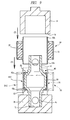
- FIG. 3 is a sectional view showing a bush (first embodiment) to be mounted on the torque rod of FIG. 2
- FIG. 4 is a view explaining the structure of a bush main body
- FIG. 5 is a view explaining the structure of a joint pin
- FIGS. 6A and 6B are views explaining the structure of a bearing
- FIGS. 7A and 7B are views explaining the structure of an elastic member.
- paired rear axles 12 are provided side by side in a longitudinal direction (horizontal direction in the drawing) of the frame 11.
- paired rear wheels 13 are mounted on both end sides along a lateral direction (depth direction in the drawing) of the frame 11 of each rear axle 12.
- Each rear axle 12 is supported by the frame 11 via a suspension device 14.
- the suspension device 14 includes a joint member 15 having one end side coupled to the frame 11, a torque rod 16 having one end side rotatably coupled to the other end side of the joint member 15, and a support member 17 rotatably coupled to the other end side of the torque rod 16 to support the rear axle 12.
- the joint member 15, the torque rod 16, and the support member 17 form a link mechanism, and paired air springs 18 and a hydraulic damper 19 are provided between the support member 17 and the frame 11.
- Each air spring 18 and the hydraulic damper 19 are adapted to expand and contract in response to vertical motions of the support member 17 with vertical motions of the rear wheel 13.
- the torque rod 16 provided between the joint member 15 and the support member 17 includes, as shown in FIG. 2 , a rod body 16a and paired mount rings 16b fixed to both end sides thereof.
- a bush 20 shown in FIG. 3 is mounted on each mount ring 16b of the torque rod 16.
- the bush 20 includes a bush main body 30, a joint pin 40, a bearing 50, and paired elastic members 60.
- the bush main body 30 includes, as shown in FIGS. 3 and 4 , an outer cylinder 31 made of steel material, and the outer cylinder 31 is fitted into the inside of the mount ring 16b of the torque rod 16.
- An inner cylinder 32 formed on the inside in a radial direction of the outer cylinder 31 has a diameter smaller than that of the outer cylinder 31, and an annular space S is formed between the outer cylinder 31 and the inner cylinder 32.
- the length of the inner cylinder 32 in its axial direction is set to be longer than that of the outer cylinder 31 in its axial direction, and each end of the inner cylinder 32 in its axial direction extends to the outside of the outer cylinder 31.
- the inner cylinder 32 includes a main-body cylinder portion 32a, and paired thin portions 32b thinner than the main-body cylinder portion 32a are provided to respective ends of the main-body cylinder portion 32a.
- Each thin portion 32b is placed outside the outer cylinder 31, and as shown in FIG. 3 , is folded and deformed inward in the radial direction, so that each thin portion 32b becomes a bent portion 33 at the time of assembling the bush 20.
- a cushion member 34 made of elastic material such as rubber or elastomer is provided by vulcanization adhesion and the like.
- the cushion member 34 is formed into a cylindrical shape, and elastically deformed when the outer cylinder 31 and the inner cylinder 32 are relatively moved with respect to each other in a radial direction or a tilt direction.
- the cushion member 34 is adapted to absorb displacement, that is, vibrations exerted on the inner cylinder 32 or the outer cylinder 31 to prevent its transmission from one to the other.
- the bush main body 30 is composed of the outer cylinder 31, the inner cylinder 32, and the cushion member 34.
- the joint pin 40 is, as shown in FIGS. 3 and 5 , formed from a pipe member made from steel material, and on the inside in a radial direction of the inner cylinder 32 (the bush main body 30), extends so as to penetrate through the inner cylinder 32 in the axial direction. Both sides in an axial direction of the joint pin 40 are paired mount portions 41 having a section formed into an approximately square shape (refer to FIG. 2 ), and each mount portion 41 is mounted on the joint member 15 or the support member 17 forming the suspension device 14. Each mount portion 41 is formed with a through hole 41a, and fasteners (not shown) such as fastening bolt penetrate through respective through holes 41a. With this, the joint pin 40 can be fixed to the joint member 15 or the support member 17 via the fasteners.
- a cylindrical projecting portion 42 projecting outward in the radial direction of the joint pin 40 is provided in an approximately center portion of the joint pin 40 along its axial direction, that is, between the through holes 41a of the joint pin 40.
- the outer diameter of the projecting portion 42 is set to be smaller than the inner diameter of the inner cylinder 32, and a bearing 50 is provided between the projecting portion 42 and the inner cylinder 32.
- the projecting portion 42 is rotatably provided on the inside in the radial direction of the bearing 50, and it is possible to relatively rotate the joint pin 40 around an axis of the inner cylinder 32 with respect to the inner cylinder 32 (the bush main body 30).
- the bush 20 is a rotation-type bush.
- Each side in the axial direction of the projecting portion 42 has a shoulder portion 42a smoothly continuous from an outer peripheral surface of the projecting portion 42 toward the center axis of the joint pin 40, and each shoulder portion 42a has a surface which faces an approximately axial direction of the joint pin 40 to support each elastic member 60 from the axial direction of the joint pin 40.
- paired annular concave portions 43 on which each annular lip 62 (refer to FIG. 7 ) of each elastic member 60 is mounted are provided, and the inside portion in the radial direction of each elastic member 60 is fitted into each annular concave portion 43. With this, it is possible to prevent each annular lip 62 from being moved in an axial direction with respect to the joint pin 40.
- An outer peripheral surface 44 of the projecting portion 42 (an outermost peripheral surface in the radial direction of the projecting portion 42) is formed in approximately parallel with the inner peripheral surface of the inner cylinder 32 as shown in FIG. 3 .
- This outer peripheral surface 44 has an outer diameter to overlap each bent portion 33 of the inner cylinder 32 as viewed from the axial direction of the joint pin 40 (refer to a portion with a reference character T in the drawing). That is, an expanding amount h inward in the radial direction of each bent portion 33 is set at an amount that allows a tip portion of each bent portion 33 (the inside in the radial direction) to reach each shoulder portion 42a smoothly continuous to the outer peripheral surface 44.
- each elastic member 60 is supported between each shoulder portion 42a and each bent portion 33, thereby reliably preventing the joint pin 40 and the bearing 50 from falling from the inner cylinder 32 (the bush main body 30).
- the elastic member 60 has only to be held in the axial direction without falling when an external force is exerted in the axial direction.
- the expanding amount h of each bent portion 33 inward in the radial direction can also be made small, and the outer peripheral surface 44 and each bent portion 33 may be set so as not to overlap each other when viewed in the axial direction of the joint pin 40.
- the elastic members 60 of the present invention also serve as dust seals
- the elastic members 60 preferably have flexibility with a rubber stiffness on the order of 50 degrees to 80 degrees (JIS K6253 A-type durometer) in view of adhesive and sealing properties with respect to the projecting portion 42, and therefore the expanding amount h is preferably adjusted according to the stiffness of the elastic member 60.
- the bearing 50 provided between the projecting portion 42 and the inner cylinder 32 is formed into an approximately cylindrical shape as shown in FIG. 6 , and formed of resin material such as plastic.
- the bearing 50 is provided with a notched portion 51 along its axial direction. With this, the bearing 50 can be elastically deformed in its radial direction.
- paired bearing projections 52 projecting toward the inside in the radial direction of the joint pin 40 are integrally provided.
- Each of the bearing projections 52 is, as shown in FIG. 3 , supported in contact with the shoulder portion 42a of the projecting portion 42.
- the bearing 50 is integrated with the joint pin 40, and cannot be relatively moved with respect to it in the axial direction.
- a predetermined amount of sliding grease intervenes, thereby making the joint pin 40 smoothly rotatably guided by the bearing 50.
- the notched portion 51 also functions as a grease reservoir holding the sliding grease.
- Each elastic member 60 held between each shoulder portion 42a and each bent portion 33 is, as shown in FIG. 7 , formed into an annular shape.
- the elastic member 60 can be appropriately selectable based on the intended use of the bush 20.
- An annular step portion 61 is provided on an outer peripheral edge on one side in the axial direction of the elastic member 60, and the bearing projection 52 enters the annular step portion 61 for close adhesion as shown in FIG. 3 . That is, as with each shoulder portion 42a of the projecting portion 42, both sides in the axial direction of the bearing 50 are supported by the respective elastic members 60.
- each annular lip 62 On the inside in the radial direction of the elastic members 60, the paired annular lips 62 are formed side by side in the axial direction of the elastic members 60.
- the inner diameter of each annular lip 62 is set to be smaller than the outer diameter of the annular concave portion 43 of the joint pin 40, and each annular lip 62 enters the annular concave portion 43 as being elastically deformed. With this, each annular lip 62 inhibits entrance of foreign substances such as rainwater and dusts between the joint pin 40 and the bearing 50.
- the elastic members 60 function as sealing members.
- each elastic member 60 is fixed to the inside of the inner cylinder 32 together with the bearing 50, and each annular lip 62 slidably abuts on the joint pin 40. Furthermore, note that a predetermined amount of grease is also intervenes between each annular lip 62 and the annular concave portion 43.
- the elastic members 60 are incorporated in a pressured state between each shoulder portion 42a and each bent portion 33, and the axial-direction length L1 of the elastic members 60 in an assembled state of the bush 20 shown in FIG. 3 is smaller than the axial-direction length L2 of the elastic members 60 in a natural state (non-load state) shown in FIG. 7 (L1 ⁇ L2).
- each elastic member 60 is nipped in a compressed and deformed state between each shoulder portion 42a and the each bent portion 33. With this, while an axial force with which the joint pin 40 is relatively moved in the axial direction with respect to the inner cylinder 32 is absorbed, backlash of the joint pin 40 and the bearing 50 with respect to the inner cylinder 32 (the bush main body 30) is suppressed.
- each elastic member 60 in a pressured state, sealing properties between each elastic member 60 and each bent portion 33 is improved, thereby inhibiting entrance of foreign substances such as rainwater and dusts from a space between each elastic member 60 and each bent portion 33 to a space between the joint pin 40 and the bearing 50. Furthermore, note that even when the joint pin 40 relatively moves in the axial direction with respect to the inner cylinder 32, each elastic member 60 is compressed and deformed and therefore is not away from each shoulder portion 42a and each bent portion 33. That is, during absorption of vibrations of the bush 20 (during operation), the function of each elastic member 60 as a sealing member is not impaired.
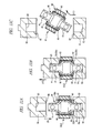
- FIG. 8 is a view explaining a procedure of mounting the bearing on the joint pin (first assembling process)
- FIG. 9 is a view explaining a procedure of mounting the bush main body on a joint pin-bearing assembly (second assembling process)
- FIG. 10 is a view explaining a procedure of mounting each elastic member on a joint pin-bush main body assembly (third assembling process)
- FIGS. 11A, 11B, and 11C are views explaining a swaging process (fourth assembling process) of bending and deforming each thin portion.
- the second jig 72 is moved down so as to approach the first jig 70.
- one bearing projection 52 of the bearing 50 goes over the other shoulder portion 42a of the joint pin 40 to cause the bearing 50 to be extended as indicated by arrows (3) in the drawing.
- the bearing 50 is easily flexible due to the notched portion 51, it is possible to mount the bearing 50 on the joint pin 40 with substantially little resistance.
- the bearing 50 is placed at a fixed position to cover the projecting portion 42 of the joint pin 40. That is, bearing projections 52 of the bearing 50 is supported by respective shoulder portions 42a of the joint pin 40. With this, a joint pin-bearing assembly SA1 is completed.
- the bush main body 30 assembled in a separate process in advance is prepared.
- the joint pin-bearing assembly SA1 being set to the first jig 70
- the bush main body 30 and the joint pin-bearing assembly SA1 are axially aligned with each other.
- the bush main body 30 is moved so as to approach the joint pin 40 by using a third jig 74 from the other mount portion 41 side of the joint pin 40.
- an annular pushing portion 75 of the third jig 74 is caused to abut on the other thin portion 32b of the inner cylinder 32.
- the third jig 74 is moved down so as to approach the first jig 70.
- the bearing 50 is fitted in the inner cylinder 32 of the bush main body 30 so that the inner cylinder 32 of the bush main body 30 gradually covers the outer peripheral surface of the bearing 50.
- the bearing projections 52 are supported by the respective shoulder portions 42a, the bearing 50 is not relatively moved with respect to the joint pin 40.
- the bush main body 30 is placed at a fixed position with respect to the bearing 50.
- this assembly takes a state in which a center potion in the axial direction of the bearing 50 and a center portion in the axial direction of the bush main body 30 are coaxially arranged, thereby completing a joint pin-bush main body assembly SA2.
- the paired elastic members 60 each of which is formed into a predetermined shape in a separate process in advance, are prepared, and oil (not shown) for allowing each of the elastic members 60 to be easily mounted on the joint pin-bush main body assembly SA2 is applied onto each elastic member 60.
- one elastic member 60 is placed on an annular convex portion 77 of a fourth jig 76.
- the annular step portion 61 of the elastic member 60 is set to be oriented to the other side (upward in the drawing).
- the joint pin-bush main body assembly SA2 is moved so as to approach the fourth jig 76, and one mount portion 41 of the joint pin 40 is inserted into a support concave portion 78 of the fourth jig 76, thereby setting the joint pin-bush main body assembly SA2 into the fourth jig 76.
- the other elastic member 60 is moved so as to approach the other thin portion 32b of the inner cylinder 32. Then, as indicated by an arrow (8) in the drawing, the other elastic member 60 is pressed from the other mount portion 41 side of the joint pin 40 by using a fifth jig 79. At this time, an annular pressing portion 80 of the fifth jig 79 is caused to abut on the other elastic member 60.
- each elastic member 60 is placed at a fixed position with respect to the joint pin-bush main body assembly SA2. That is, the annular lips 62 of the elastic members 60 respectively enter the annular concave portions 43 of the joint pin 40, and the bearing projections 52 of the bearing 50 respectively enter the annular step portions 61 of the elastic members 60. With this, provisional mounting of each elastic member 60 on the joint pin-bush main body assembly SA2 is completed.
- the joint pin-bush main body assembly SA2 with each elastic member 60 provisionally mounted thereon is moved to a sixth jig 81.
- each elastic member 60 is prevented from falling from the joint pin-bush main body assembly SA2 at the time of moving to the sixth jig 81.
- one mount portion 41 of the joint pin 40 of the joint pin-bush main body assembly SA2 is inserted into a support concave portion 82 of the sixth jig 81, and the joint pin-bush main body assembly SA2 is set to the sixth jig 81.
- one thin portion 32b of the inner cylinder 32 is caused to abut on a first swaging concave portion 83 formed on an opening side of the support concave portion 82 of the sixth jig 81.
- each thin portion 32b of the inner cylinder 32 is folded and deformed along the shape of the respective swaging concave portions 83 and 86 toward the inside in the radial direction.
- each thin portion 32b becomes a bent portion 33.
- the elastic members 60 can absorb deformation errors of the bent portions 33. Therefore, it is not necessary to take account of spring-back and the like of each thin portion 32b, and high processing accuracy.
- the seventh jig 84 is moved up with respect to the sixth jig 81 to extract the other mount portion 41 from the support concave portion 85 of the seventh jig 84.
- the one mount portion 41 is extracted from the support concave portion 82 of the sixth jig 81, thereby completing the bush 20.
- the moving up/down operations of the second jig 72, the third jig 74, the fifth jig 79, and the seventh jig 84 can be automatically performed with an actuator such as hydraulic cylinder being taken as a driving source. Furthermore, in the moving up/down operations of the second jig 72, the third jig 74, and the fifth jig 79, since the driving force (swaging process) as much as that of the seventh jig 84 is not required, the operations may be performed manually by the operator.
- the joint pin 40 extending in the axial direction of the inner cylinder 32 is provided on the inside in the radial direction of the inner cylinder 32
- the projecting portion 42 projecting outward in the radial direction of the joint pin 40 is provided to the joint pin 40
- the shoulder portions 42a are provided on both sides in the axial direction of the projecting portion 42
- the bearing 50 guiding relative rotation of the joint pin 40 with respect to the inner cylinder 32 is provided between the inner cylinder 32 and the projecting portion 42
- the bent portions 33 being bent toward the inside in the radial direction of the inner cylinder 32 are provided on both sides in the axial direction of the inner cylinder 32
- the elastic member 60 is incorporated between each bent portion 33 and each shoulder portion 42a.
- the bent portions 33 support the projecting portion 42 from both sides in the axial direction via the elastic members 60, thereby preventing the joint pin 40 from falling from the inner cylinder 32. Therefore, the number of components can be reduced by omitting a packing seal, a fixing ring and the like conventionally used and, in turn, the assembling process can be simplified to reduce manufacturing cost. Also, since the joint pin 40 is prevented from falling via the elastic members 60, impact and vibration load exerted in the axial direction of the joint pin 40 can be absorbed by the elastic members 60, and backlash of the joint pin 40 with respect to the inner cylinder 32 can be further suppressed. Therefore, premature failure on the bush 20 can be prevented and the life of the bush 20 can be enhanced. Furthermore, when the bush 20 is assembled by folding and deforming the bent portions 33, deformation errors of the bent portions 33 can be absorbed by the elastic member 60, and since the bush 20 is assembled without high assembling accuracy, it is possible to reduce the manufacturing cost of the bush 20.
- the elastic members 60 support both sides in the axial direction of the bearing 50, it is possible to prevent backlash of the bearing 50 in the axial direction. Thus, it is possible to prevent the occurrence of unusual sound due to backlash of the bearing 50 and unbalanced wear of the bearing 50 due to an unbalanced load.
- each elastic member 60 is incorporated in a pressured state between the shoulder portion 42a and the bent portion 33, sealing properties by the elastic members 60 can be improved. That is, with the elastic members 60 in a pressured state, dusts and the like can be reliably inhibited from entering between the bearing 50 and the projecting portion 42.
- the expanding amount h inward in the radial direction of each bent portion 33 is set as an expanding amount h overlapping the outer peripheral surface 44 of the projecting portion 42 of the joint pin 40, and therefore the strength of the joint pin 40 against falling from the inner cylinder 32 can be improved. That is, the stiffness in the axial direction of the bush 20 can be increased.
- the bearing projections 52 projecting inside in the radial direction of the joint pin 40 are provided on both sides in the axial direction of the bearing 50, and the bearing projections 52 are caused to be pressed to support the shoulder portions 42a.
- the joint pin 40 and the bearing 50 can be integrated so as not to be able to relatively move with respect to the axial direction. Therefore, the strength of the joint pin 40 against falling from the inner cylinder 32 can be further improved.
- the joint member 15 corresponds to one member (the vehicle body) and the mount rings 16b of the torque rod 16 correspond to the other member (the axle) .
- the mount rings 16b of the torque rod 16 correspond to one member (the vehicle body), and the support member 17 corresponds to the other member (the axle).
- FIG. 12 is a fragmentary enlarged view showing a bush according to the second embodiment of the present invention.
- the bearing and each elastic member of the bush 90 of the second embodiment differ from those of the bush 20 of the first embodiment in shape.
- a bearing 91 of a bush 90 is formed into a simple cylindrical shape, and compared with the bearing 50 in the first embodiment, the notched portion 51 and each bearing projection 52 are omitted, and the dimension in the axial direction is approximately equal to the length in the axial direction of the projecting portion 42 of the joint pin 40.
- the inner diameter of the bearing 91 is set to be approximately equal to the outer diameter of the projecting portion 42 of the joint pin 40, and the bearing 91 is assembled from the axial direction of the joint pin 40.
- each elastic member 92 of the bush 90 compared with each elastic member 60 in the first embodiment, the annular step portion 61 is omitted, and both sides in the axial direction of the bearing 91 are directly supported by one end face in the axial direction of each elastic member 92.
- the bearing 91 does not have bearing projections with respect to the joint pin 40.
- the bearing 91 since the bearing 91 is formed into a simple cylindrical shape without bearing projections, the bearing 91 can be formed by forming polyacetal resin, PTFE resin, or the like into a long pipe shape and cutting it into a length as required. Therefore, it can be produced without a mold tool or the like for molding the bearing 91, and reduced in manufacturing cost.
- FIG. 13 is a fragmentary enlarged view showing a bush according to the third embodiment of the present invention.
- a bush 100 according to the third embodiment is different in shape of the bearing.
- a bearing 101 of the bush 100 is a so-called half-divided type, and is formed of a first divided body 102 and a second divided body 103.
- Each of the divided bodies 102 and 103 does not have a notched portion along the axial direction.
- each of the divided bodies 102 and 103 is assembled from both sides in the axial direction of the joint pin 40 toward the projecting portion 42.
- a predetermined space O is formed at the time of assembling the bush 100.
- the divided bodies 102 and 103 are respectively pressed by the elastic members 60, and the bearing projections 52 are respectively pressed and supported by the shoulder portions 42a.
- the predetermined space O functions as a grease reservoir holding sliding grease.
- the bearing projections 52 of the divided bodies 102 and 103 have a length in the radial direction set to be long similar to the first embodiment, that is, set to be thicker than the main body portion of the divided bodies 102 and 103, the length being approximately equal to or larger than the expanding amount h (refer to FIG. 3 ) of the bent portion 33. With this, a pressure-receiving area of a restraint force receiving from each bent portion 33 via the elastic member 60 is increased to achieve reliable prevention of falling of the bearing 101 from the inner cylinder 32.
- the elastic members 60 receive a load in the axial direction at the time of relative movement in the axial direction of the inner cylinder 32 and the joint pin 40, portions in close contact to the shoulder portions 42a of the elastic members 60 are in a free state in which the outside in the axial direction is not restricted.
- the load in the axial direction is not exerted more than required onto the elastic members 60 and, in turn, wear of the elastic members 60 are suppressed.
- each of the divided bodies 102 and 103 are formed of a bearing-specific resin with a relatively high hardness.
- the notched portion 51 extending in the axial direction for assembling is not required to be provided. That is, when the bearing 50 is mounted on the joint pin 40 as being elastically deformed as is the case of the bearing 50 of the first embodiment, if the amount of elastic deformation is large, a crack or the like may occur in the bearing 50. This invites complexity of the bush assembling process and shortening of the life of the bush.
- each of the divided bodies 102 and 103 is prepared as a half-divided type, thereby shorting an amount of mounting (a fitting length) on the joint pin 40.
- a notched portion extending in the axial direction may be provided for the purpose of absorbing dimensional errors of the inner diameter of the bearing 50 and the outer diameter of the projecting portion 42.
- the present invention is not meant to be restricted to each of the embodiments described above, and it goes without saying that the present invention can be variously changed within a range not deviating from the gist of the invention.
- the present invention is not meant to be restricted to this, and each of the bearings 50, 91, and 101 may be in a state not in contact with each elastic member 60. In this case, even if the bearing moves in the axial direction with respect to the joint pin, the bearing makes contact with the elastic members and therefore does not produce an unusual sound.
- each elastic member 60 is incorporated in a pressured state between the bent portion 33 and the shoulder portion 42a in each of the embodiments described above, the present invention is not meant to be restricted to this, and each elastic member 60 can be incorporated in a non-pressured state according to the specifications of the bush, that is, the stiffness required for the bush with respect to the axial direction.
- the bush placed on the rear axle 12 side of the torque rod 16 (refer to FIG. 1 ) is mounted on the support member 17 in each of the embodiments described above, the present invention is not meant to be restricted to this and, as a matter of course, the bush may be directly mounted on the rear axle 12 not via the support member 17.
- the present invention is not meant to be restricted to this and can be used for the purpose of using a rotation-type bush, that is, the present invention can be used at a mount portion of an engine mount, a stabilizer bar, or the like.
- the bush is provided between one member and the other member to absorb impact and vibrations transmitted between the members, is assembled to a torque rod connecting a vehicle body and an axle of a vehicle such as truck, bus, or the like to allow a predetermined range of a relative movement of the axle with respect to the vehicle body, and is used to absorb propagation of impact vibrations inputted from a road surface to the vehicle body.
Landscapes
- Engineering & Computer Science (AREA)
- Mechanical Engineering (AREA)
- General Engineering & Computer Science (AREA)
- Manufacturing & Machinery (AREA)
- Springs (AREA)
- Vibration Prevention Devices (AREA)
- Vehicle Body Suspensions (AREA)
Applications Claiming Priority (2)
| Application Number | Priority Date | Filing Date | Title |
|---|---|---|---|
| JP2009254378A JP5038377B2 (ja) | 2009-11-05 | 2009-11-05 | ブッシュ |
| PCT/JP2010/069450 WO2011055713A1 (ja) | 2009-11-05 | 2010-11-01 | ブッシュ |
Publications (2)
| Publication Number | Publication Date |
|---|---|
| EP2497970A1 true EP2497970A1 (de) | 2012-09-12 |
| EP2497970A4 EP2497970A4 (de) | 2017-10-18 |
Family
ID=43969952
Family Applications (1)
| Application Number | Title | Priority Date | Filing Date |
|---|---|---|---|
| EP10828273.2A Withdrawn EP2497970A4 (de) | 2009-11-05 | 2010-11-01 | Buchse |
Country Status (5)
| Country | Link |
|---|---|
| EP (1) | EP2497970A4 (de) |
| JP (1) | JP5038377B2 (de) |
| CN (1) | CN102667220A (de) |
| MY (1) | MY179488A (de) |
| WO (1) | WO2011055713A1 (de) |
Cited By (1)
| Publication number | Priority date | Publication date | Assignee | Title |
|---|---|---|---|---|
| EP3290316A1 (de) * | 2016-09-01 | 2018-03-07 | Robert Bosch GmbH | Schutzanordnung sowie hohlkörperanordnung, insbesondere sattelrohr |
Families Citing this family (4)
| Publication number | Priority date | Publication date | Assignee | Title |
|---|---|---|---|---|
| JP6100213B2 (ja) * | 2014-07-25 | 2017-03-22 | 豊田鉄工株式会社 | 車両用ペダル装置の軸受部構造および鍔付きブッシュ |
| CN108819638B (zh) * | 2018-06-30 | 2021-10-15 | 宁国九鼎橡塑制品有限公司 | 一种悬挂减震衬套及其制备方法 |
| CN108973566B (zh) * | 2018-08-15 | 2021-04-13 | 安徽奥丰汽车配件有限公司 | 一种汽车底盘悬架用的防异响橡胶衬套 |
| CN113550994A (zh) * | 2020-04-26 | 2021-10-26 | 普尔曼公司 | 组合式衬套 |
Family Cites Families (12)
| Publication number | Priority date | Publication date | Assignee | Title |
|---|---|---|---|---|
| JPS5990639A (ja) | 1982-11-12 | 1984-05-25 | 極東開発工業株式会社 | 破砕機 |
| JPH01312239A (ja) * | 1988-02-03 | 1989-12-18 | Bridgestone Corp | ブッシュ組立体 |
| JPH02225833A (ja) * | 1989-02-27 | 1990-09-07 | Kinugawa Rubber Ind Co Ltd | 防振ブッシュ |
| JPH04129942U (ja) * | 1991-05-21 | 1992-11-30 | 東海ゴム工業株式会社 | 摺動ブツシユ |
| TW235990B (de) * | 1992-12-16 | 1994-12-11 | Taylor Gordon Joseph | |
| JP3537176B2 (ja) * | 1994-03-10 | 2004-06-14 | 山下ゴム株式会社 | 摺動ブッシュ及びその製法 |
| JPH10153237A (ja) | 1996-11-21 | 1998-06-09 | Saitama Kiki Kk | トルクロッドブッシュ |
| JPH1151099A (ja) * | 1997-08-06 | 1999-02-23 | Toyo Tire & Rubber Co Ltd | ゴムブッシュ |
| JPH11117974A (ja) * | 1997-10-16 | 1999-04-27 | Toyo Tire & Rubber Co Ltd | ゴムブッシュ |
| JP3858144B2 (ja) * | 2001-08-28 | 2006-12-13 | 東洋ゴム工業株式会社 | 防振装置 |
| JP3972669B2 (ja) * | 2002-02-05 | 2007-09-05 | 東海ゴム工業株式会社 | 鉄道車両用防振ゴムブッシュとその製造・組付方法 |
| JP2009174675A (ja) * | 2008-01-28 | 2009-08-06 | Tokai Rubber Ind Ltd | 自動車用トルクロッド |
-
2009
- 2009-11-05 JP JP2009254378A patent/JP5038377B2/ja not_active Expired - Fee Related
-
2010
- 2010-11-01 EP EP10828273.2A patent/EP2497970A4/de not_active Withdrawn
- 2010-11-01 MY MYPI2012700193A patent/MY179488A/en unknown
- 2010-11-01 WO PCT/JP2010/069450 patent/WO2011055713A1/ja active Application Filing
- 2010-11-01 CN CN201080050373XA patent/CN102667220A/zh active Pending
Non-Patent Citations (1)
| Title |
|---|
| See references of WO2011055713A1 * |
Cited By (1)
| Publication number | Priority date | Publication date | Assignee | Title |
|---|---|---|---|---|
| EP3290316A1 (de) * | 2016-09-01 | 2018-03-07 | Robert Bosch GmbH | Schutzanordnung sowie hohlkörperanordnung, insbesondere sattelrohr |
Also Published As
| Publication number | Publication date |
|---|---|
| CN102667220A (zh) | 2012-09-12 |
| MY179488A (en) | 2020-11-08 |
| JP2011099512A (ja) | 2011-05-19 |
| JP5038377B2 (ja) | 2012-10-03 |
| WO2011055713A1 (ja) | 2011-05-12 |
| EP2497970A4 (de) | 2017-10-18 |
Similar Documents
| Publication | Publication Date | Title |
|---|---|---|
| US8905417B2 (en) | Stabilizer link and production method therefor | |
| EP2497970A1 (de) | Buchse | |
| JP4129632B2 (ja) | 弾性軸継手 | |
| CN105814335B (zh) | 隔振支承装置 | |
| JP4404849B2 (ja) | ブッシュ | |
| JP6754311B2 (ja) | スタビライザブッシュ | |
| JP6343535B2 (ja) | 筒型防振装置 | |
| EP1959173B1 (de) | Dichtungsvorrichtung | |
| CN101909911B (zh) | 车辆稳定器 | |
| JP2000185538A (ja) | 複合スタビライザ―バ―リンク | |
| JP4395760B2 (ja) | 防振ブッシュ | |
| KR20130059210A (ko) | 자동차용 필로우 볼 부시 및 그 조립방법 | |
| EP2110273B1 (de) | Federbeinstützlager in einer Fahrzeugaufhängung mit elastischer Lagerung für die Kolbenstange eines Schwingungsdämpfers | |
| US9718322B2 (en) | Shock absorbers having a composite base assembly with an over-molded closure insert | |
| KR101322426B1 (ko) | 자동차용 필로우 볼 부시 | |
| JP6973696B1 (ja) | 懸架装置およびその組立方法 | |
| US6199672B1 (en) | Dust cover mounting structure | |
| JPH0914328A (ja) | 油圧緩衝器におけるリバウンドクッション装置 | |
| JP2007127173A (ja) | バウンドストッパ | |
| KR102463446B1 (ko) | 스테빌라이저 부시 | |
| CN112585364B (zh) | 接头和用于制造这种接头的方法 | |
| KR101361246B1 (ko) | 자동차의 커플드 토션 빔 액슬 | |
| US11873901B2 (en) | Integrated sealing device for motorcycle suspensions | |
| CN213017255U (zh) | 一种稳定杆及其球头总成 | |
| JP2000225940A (ja) | 鉄道車両軸はり装置用防振ゴムブッシュ |
Legal Events
| Date | Code | Title | Description |
|---|---|---|---|
| PUAI | Public reference made under article 153(3) epc to a published international application that has entered the european phase |
Free format text: ORIGINAL CODE: 0009012 |
|
| 17P | Request for examination filed |
Effective date: 20120427 |
|
| AK | Designated contracting states |
Kind code of ref document: A1 Designated state(s): AL AT BE BG CH CY CZ DE DK EE ES FI FR GB GR HR HU IE IS IT LI LT LU LV MC MK MT NL NO PL PT RO RS SE SI SK SM TR |
|
| DAX | Request for extension of the european patent (deleted) | ||
| RA4 | Supplementary search report drawn up and despatched (corrected) |
Effective date: 20170914 |
|
| RIC1 | Information provided on ipc code assigned before grant |
Ipc: B60G 11/27 20060101ALI20170908BHEP Ipc: F16F 1/38 20060101AFI20170908BHEP Ipc: B60G 7/00 20060101ALI20170908BHEP |
|
| GRAP | Despatch of communication of intention to grant a patent |
Free format text: ORIGINAL CODE: EPIDOSNIGR1 |
|
| INTG | Intention to grant announced |
Effective date: 20180918 |
|
| RIN1 | Information on inventor provided before grant (corrected) |
Inventor name: ARAI, KAZUO Inventor name: KOIKE, KIYOTAKA Inventor name: IIDA, MASAKAZU |
|
| STAA | Information on the status of an ep patent application or granted ep patent |
Free format text: STATUS: THE APPLICATION IS DEEMED TO BE WITHDRAWN |
|
| 18D | Application deemed to be withdrawn |
Effective date: 20190129 |