EP2487010B1 - Roboterhand und Robotervorrichtung - Google Patents
Roboterhand und Robotervorrichtung Download PDFInfo
- Publication number
- EP2487010B1 EP2487010B1 EP12154851.5A EP12154851A EP2487010B1 EP 2487010 B1 EP2487010 B1 EP 2487010B1 EP 12154851 A EP12154851 A EP 12154851A EP 2487010 B1 EP2487010 B1 EP 2487010B1
- Authority
- EP
- European Patent Office
- Prior art keywords
- finger
- unit
- gear
- robot hand
- rotates
- Prior art date
- Legal status (The legal status is an assumption and is not a legal conclusion. Google has not performed a legal analysis and makes no representation as to the accuracy of the status listed.)
- Not-in-force
Links
- 230000008878 coupling Effects 0.000 claims description 104
- 238000010168 coupling process Methods 0.000 claims description 104
- 238000005859 coupling reaction Methods 0.000 claims description 104
- 230000009471 action Effects 0.000 claims description 34
- 230000007246 mechanism Effects 0.000 claims description 26
- 239000000758 substrate Substances 0.000 description 18
- 230000004048 modification Effects 0.000 description 12
- 238000012986 modification Methods 0.000 description 12
- 230000008859 change Effects 0.000 description 11
- 238000010586 diagram Methods 0.000 description 11
- 239000013256 coordination polymer Substances 0.000 description 4
- 125000006850 spacer group Chemical group 0.000 description 4
- 238000000034 method Methods 0.000 description 3
- 230000009467 reduction Effects 0.000 description 3
- 230000002452 interceptive effect Effects 0.000 description 2
- 239000000463 material Substances 0.000 description 2
- 230000008569 process Effects 0.000 description 2
- 230000001105 regulatory effect Effects 0.000 description 2
- 230000008901 benefit Effects 0.000 description 1
- 238000004519 manufacturing process Methods 0.000 description 1
- 239000011347 resin Substances 0.000 description 1
- 229920005989 resin Polymers 0.000 description 1
Images


Classifications
-
- B—PERFORMING OPERATIONS; TRANSPORTING
- B25—HAND TOOLS; PORTABLE POWER-DRIVEN TOOLS; MANIPULATORS
- B25J—MANIPULATORS; CHAMBERS PROVIDED WITH MANIPULATION DEVICES
- B25J15/00—Gripping heads and other end effectors
- B25J15/08—Gripping heads and other end effectors having finger members
- B25J15/10—Gripping heads and other end effectors having finger members with three or more finger members
Definitions
- the present invention relates to a robot hand and a robot apparatus.
- a robot hand that is attached to a robot apparatus such as an industrial robot arm and grips or releases an object to perform predetermined work.
- a multifunction robot hand is proposed that grips, for example, a tool to perform work such as assembly of a component and grips a very small component to accurately arrange the component.
- three finger units that grip an object can be opened and closed by a cam follower mechanism. Further, two finger units among the three finger units are guided by a pair of circumferential grooves formed on the same plane and are enable to turn symmetrically to each other.
- the robot hand is considered to be capable of gripping various objects including objects having dissimilar shapes and different sizes.
- US 2006/0012197 A1 describes a robotic hand with a base having fingers rotated by a worm that rotates in association with the rotation of a worm wheel rotated by a motor .
- US 2010/0176615 A1 describes a multi-fingered robot hand with a minimum required number of joints in finger mechanisms and capable of stably grasping a variety of articles.
- the hand includes a first palm portion provided with three finger mechanism, a second palm portion provided with one finger mechanism and a palm joint that connects the two palm portions.
- the two outer of the three fingers are laterally moveable to adjust the spread between the fingers by means of two gears that rotate in opposite directions in association with the rotation of a worm rotated by a motor.
- An advantage of some aspects of the invention is to provide a robot hand and a robot apparatus that can grip, simply and at low cost, various objects including objects having dissimilar shapes and different sizes.
- An aspect of the invention is directed to a robot hand including: three or more finger units including a first finger unit and a second finger unit; a driving unit that causes the three or more finger units to perform an opening and closing action; and a finger-unit moving mechanism that changes a direction in which the opening and closing action of the first finger unit and the second finger unit is performed.
- the finger-unit moving mechanism includes: a worm wheel; a motor that rotates the worm wheel; and a worm that rotates in a direction different from a rotating direction of the worm wheel in association with the rotation of the worm wheel.
- a first gear that rotates in a direction different from the rotating direction of the worm in association with the rotation of the worm is provided in the first finger unit.
- a second gear that rotates in a direction opposite to the rotating direction of the first gear in association with the rotation of the worm is provided in the second finger unit.
- the first finger unit and the second finger unit rotate, when the motor rotates, in a direction in which the finger units move close to each other or a direction in which the finger units move away from each other.
- the direction in which the opening and closing action of the first finger unit and the second finger unit among the three or more finger units is performed is changed when the motor rotates. Therefore, it is possible to change, according to the shape of an object, a direction in which the finger units grip the object.
- the direction can be changed such that the finger units wrap up the object (the finger units are equally arranged around the object).
- the object is a rod-like member
- the direction can be changed such that the finger units hold the object (the finger units are opposed to each other via the object).
- the robot hand can stably grip the spherical body and the rod-like member according to the change of the direction in which the opening and closing action of the finger units is performed.
- a space between a rotating shaft of the first gear and a rotating shaft of the second gear may be kept fixed.
- the first finger unit including the first gear and the second finger unit including the second gear respectively rotate in fixed positions. Therefore, compared with a configuration in which the space between the rotating shaft of the first gear and the rotating shaft of the second gear fluctuates, it is possible to realize simplification of the apparatus configuration.
- a rotation angle at which the first gear rotates and the first finger unit rotates and a rotation angle at which the second gear rotates and the second finger unit rotates may be equal to each other.
- the first finger unit including the first gear and the second finger unit including the second gear rotate at the same number of revolutions and at the same angle each other. Therefore, it is easy to perform posture control for an object. Compared with a configuration in which a rotation angle of the first gear and a rotation angle of the second gear are different when the first gear and the second gear rotate at the same number of revolutions, it is possible to simplify the apparatus configuration.
- the three or more finger units may include three finger units.
- the finger-unit moving mechanism may change a direction in which the opening and closing action of two finger units among the three finger units is performed.
- the direction in which the opening and closing action of the two finger units among the three finger units is performed is changed when the motor rotates. Therefore, it is possible to change, according to the shape of an object, a direction in which the three finger units grip the object.
- the direction can be changed such that the three finger units wrap up the object (the three finger units are equally arranged around the object).
- the object is a rod-like member
- the direction can be changed such that the three finger units hold the object (the two finger units and the one finger unit are opposed to one another via the object). Therefore, it is possible to stably grip the spherical body and the rod-like member while holding down the number of arranged finger units to a necessary minimum.
- the three or more finger units may include four or more finger units.
- the robot hand may include a coupling unit that couples to one ends of the three or more finger units.
- the driving unit may drive the coupling unit to thereby move the three or more finger units in synchronization with one another in a direction in which the finger units move close to one another or away from one another.
- a first coupling member that rotates in a direction same as the rotating direction of the first gear in association with the rotation of the worm may be provided in a portion of the first finger unit coupled to the coupling unit.
- a second coupling member that rotates in a direction same as the rotating direction of the second gear in association with the rotation of the worm may be provided in a portion of the second finger unit coupled to the coupling unit.
- the first finger unit and the second finger unit rotate in a state in which the finger units are coupled to the coupling unit. Therefore, the direction in which the opening and closing action of the first finger unit and the second finger unit is performed is stably changed.
- the coupling unit may be attached to a screw shaft and move along the screw shaft according to the driving by the driving unit.
- the first finger unit and the second finger unit may perform the opening and closing action when the first coupling member and the second coupling member move according to the movement of the coupling unit.
- this robot hand it is possible to simultaneously perform a change of the direction in which the opening and closing action of the first finger unit and the second finger unit is performed and the opening and closing action of the first finger unit and the second finger unit. For example, this can be realized by driving the finger-unit moving mechanism while moving the coupling unit in the up down direction.
- a rotating shaft of the first gear and a rotating shaft of the first coupling member may be coaxial with each other.
- a rotating shaft of the second gear and a rotating shaft of the second coupling member may be coaxial with each other.
- the driving unit may move the three or more finger units close to one another from directions different from one another and move the three or more finger units away from one another in directions different from one another.
- the three or more finger units close toward the center without interfering with one another. Consequently, for example, even in griping a very small component, it is possible to stably grip the component.
- At least one finger unit among the three or more finger units may include a contact member including a bent section, a supporting member that rotatably supports the contact member in the bent section, and an elastic member that connects the contact member and the supporting member.
- the contact member may be bent in a direction in which the finger unit closes.
- the contact member easily comes into contact with the object. Therefore, it is easy to stably grip the object in the predetermined position.
- At least one finger unit among the three or more finger units may include a stopper that regulates a rotation angle of rotation of the contact member.
- Another aspect of the invention is directed to a robot apparatus including the robot hand.
- Fig. 1 is a side view showing an overall configuration of a robot hand according to a first embodiment of the invention.
- Fig. 2 is a perspective view showing the overall configuration of the robot hand according to the first embodiment.
- Fig. 3 is a plan view showing the overall configuration of the robot hand.
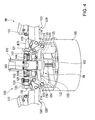
- Fig. 4 is a partially enlarged view showing a coupling unit of the robot hand according to the first embodiment.
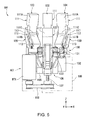
- Fig. 5 is a diagram showing a state during the operation of the robot hand according to the first embodiment.
- Fig. 6 is a diagram showing a state during the operation of the robot hand according to the first embodiment.
- Figs. 7A to 7C are plan views showing operation for changing a direction in which an opening and closing action of two finger units is performed according to the first embodiment.
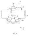
- Fig. 8 is a diagram showing a state during the operation of the robot hand according to the first embodiment.
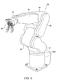
- Fig. 9 is a diagram showing an overall configuration of a robot apparatus according to a second embodiment of the invention.
- Figs. 10A and 10B are diagrams showing a modification of a robot hand.
- Fig. 11 is a diagram showing a state during the operation of the robot hand according to the modification.
- Fig. 12 is a diagram showing a state during the operation of the robot hand according to the modification.
- Figs. 13A to 13C are plan views showing operation for changing a direction in which four finger units perform an opening and closing operation according to the modification.
- Fig. 14 is a plan view showing the operation for changing the direction in which the opening and closing action of the four finger units is performed according to the modification.
- an XYZ Cartesian coordinate system shown in Fig. 1 is set. Members are explained with reference to the XYZ Cartesian coordinate system.
- the X axis and the Y axis are set in directions in which the X axis and the Y axis are parallel to the horizontal plane and orthogonal to each other.
- the Z axis is set in a direction orthogonal to each of the X axis and the Y axis (the vertical direction).
- Fig. 1 is a side view showing an overall configuration of a robot hand RH according to a first embodiment of the invention.
- Fig. 2 is a perspective view showing the overall configuration of the robot hand RH.
- Fig. 3 is a plan view showing the overall configuration of the robot hand RH.
- Fig. 4 is a partially enlarged view showing a coupling unit CN of the robot hand RH.
- the robot hand RH includes three finger units 102 to 104 (a first finger unit 103, a second finger unit 104, and a third finger unit 102), a coupling unit CN that couples the finger units 102 to 104, a driving unit ACT that drives the coupling unit CN, a cover 109 that houses the coupling unit CN and the driving unit ACT, and a finger-unit moving mechanism 130 that changes a direction in which an opening and closing action of the first finger unit 103 and the second finger unit 104 is performed.
- a coupling unit CN that couples the finger units 102 to 104
- a driving unit ACT that drives the coupling unit CN
- a cover 109 that houses the coupling unit CN and the driving unit ACT
- a finger-unit moving mechanism 130 that changes a direction in which an opening and closing action of the first finger unit 103 and the second finger unit 104 is performed.
- the "direction in which the opening and closing operation is performed” means a direction in which the first finger unit 103 opens or closes on a surface that crosses a surface on which proximal end portions of the three finger units 102 to 104 (base portions on the opposite side of the distal ends of the finger units, for example, portions where gears are attached) are arranged and includes the center line of the first finger unit 103 (a line along the longitudinal direction of the first finger unit 103).
- the "direction in which the opening and closing operation is performed” means a direction in which the second finger unit 104 opens or closes on a surface that crosses the surface on which the proximal end portions of the three finger units 102 to 104 are arranged and includes the center line of the second finger unit 104 (a line along the longitudinal direction of the second finger unit 104).
- the robot hand RH is used as a gripping device of an industrial robot that grips objects such as a tool and a component.
- the robot hand RH is not limited to the use as the industrial robot and may be used for other applications (space related robots, play equipment, etc.).
- the finger units 102 to 104 are sections that grip an object.
- the first finger unit 103 and the second finger unit 104 respectively include contact members 111, joint sections 112, supporting members 120, elastic members 113, and fixed members 121.
- a first gear 141 is attached to the proximal end portion of the fixed member 121 of the first finger unit 103.
- a second gear 142 is attached to the proximal end portions of the fixed member 121 of the second finger unit 104.
- the third finger unit 102 includes the contact member 111 that comes into contact with an object, the joint section 112, the supporting section 120 that rotatably supports the contact member 111, the elastic member 113, and a fixed member 122 that rotatably supports the supporting member 120.
- the fixed members 121 of the first finger unit 103 and the second finger unit 104 and the fixed member 122 of the third finger unit 102 have different shapes.
- the contact member 111 is bent in a direction in which the finger unit closes.
- the contact member 111 is a rigid member formed in, for example, an L shape to include a bent section 111C.
- a through-hole (not shown) is formed in the bent section 111C of the contact member 111.
- the joint section 112 having a shaft shape, both ends of which are fixed to the supporting member 120, is inserted through the through-hole. Consequently, the contact member 111 can rotate about the joint section 112.
- the configuration of the contact member 111 is not limited to this.
- the contact member 111 can rotate about the joint section 112.
- the first contact section 111A and the second contact section 111B are sections that come into contact with an object.
- the first contact section 111A is provided between the bent section 111C and one end (the distal end side of the finger unit with respect to the bent section 111C) in the contact member 111.
- the second contact section 111B is provided between the bent section 111C and the other end (the proximal end side of the finger unit with respect to the bent section 111C) in the contact member 111.
- the contact member 111 is provided to be capable of rotating about the joint section 112 in a direction in which the first contact section 111A comes into contact with the object and capable of rotating about the joint section 112 in a direction in which the second contact section 111B comes into contact with the object.
- the elastic member 113 is connected between the contact member 111 and the supporting member 120. Specifically, one end of the elastic member 113 is connected to the second contact section 111B of the contact member 111. The other end of the elastic member 113 is connected to the supporting member 120.
- a spring can be used as the elastic member 113.
- the supporting member 120 is a rigid member formed in, for example, an L shape.
- the supporting member 120 rotatably supports the contact member 111 in the bent section 111C via the joint section 112.
- the fixed member 122 is a rigid member located at the proximal end of the third finger unit 102.
- the fixed member 122 rotatably supports the supporting member 120 of the third finger unit 102 via the joint section 114.
- a through-hole (not shown) is formed in a portion of the fixed member 122 overlapping the supporting member 120.
- the joint section 114 having a shaft shape, both ends of which are fixed to the supporting member 120, is inserted through the through-hole. Consequently, the supporting member 120 can rotate about the joint section 114.
- the configuration of the supporting member is not limited to this.
- the supporting member 120 can rotate about the joint section 114.
- the fixed member 121 is a rigid member located at the proximal end of the first finger unit 103 (the second finger unit 104).
- the fixed member 121 rotatably supports the supporting member 120 of the first finger unit 103 (the second finger unit 104) via the joint section 114.
- a through-hole (not shown) is formed in a portion of the fixed member 121 overlapping the supporting member 120.
- the joint section 114 having a shaft shape, both ends of which are fixed to the supporting member 120, is inserted through the through-hole. Consequently, the supporting member 120 can rotate about the joint section 114.
- the configuration of the fixed member 121 is not limited to this.
- the supporting member 120 can rotate about the joint section 114.
- stoppers 117 that regulate the rotation of the contact members 111 are provided.
- the stopper 117 is, for example, a section that projects to extend from the supporting member 120 to the first contact section 111A side of the contact member 111.
- the stopper 117 includes, for example, a function of regulating a rotation angle (a rotation angle of the rotation of the contact member 111 about the joint section 112) to prevent the contact member 111 from rotating a predetermined angle or more with respect to the joint section 112. For example, when the elastic member 113 is in natural length, the contact member 111 (a surface on the opposite side of the contact section 111A) is in contact with the stopper 117.
- the coupling unit CN includes coupling plates 123, coupling members 124, joint sections 115 and 116, and a coupling substrate 105.
- the coupling plates 123 are, for example, tabular rigid members. Two coupling plates 123 are arranged to be opposed to each other across the supporting member 120. One ends of the coupling plates 123 are attached to the proximal end portion of the supporting member 120 via the joint section 115. The other ends of the coupling plates 123 are attached to the coupling member 124 via the joint section 116.
- One end of the coupling plate 123 is rotatable about the joint section 115.
- a through-hole (not shown) is formed in a portion of the supporting member 120 overlapping the coupling plate 123.
- the joint section 115 having a shaft shape, both ends of which are fixed to the coupling plate 123, is inserted through the through-hole.
- the through-hole may be formed in a portion of the coupling plate 123 overlapping the supporting member 120 and both the ends of the shaft-shaped joint section 115, the center of which is fixed to the supporting member 120, may be inserted through the through-hole.
- the other end of the coupling plate 123 is rotatable about the joint section 116.
- a through-hole (not shown) is formed in a portion of the coupling member 124 overlapping the coupling plate 123.
- the joint section 116 having a shaft shape, both ends of which are fixed to the coupling plate 123, is inserted through the through-hole.
- the configuration of the coupling plate 123 is not limited to this.
- the through-hole may be formed in a portion of the coupling plate 123 overlapping the coupling member 124 and both the ends of the shaft-shaped joint section 116, the center of which is fixed to the coupling member 124, may be inserted through the through-hole.
- a portion of the coupling member 124 on the opposite side of a side where the joint section 116 is provided is rotatably attached to a rotating shaft 144 inserted through the coupling substrate 105 and a cover 143.
- the coupling substrate 105 is connected to the driving unit ACT.
- the driving unit ACT includes a screw shaft 107 of a ball screw that is connected to a nut section of a ball screw included in the coupling substrate 105 and integrally lifts and lowers the coupling substrate 105, a driving unit MTR that drives the screw shaft 107, and a pulley 108 that transmits the rotation of the driving unit MTR.
- the finger-unit moving mechanism 130 includes a worm wheel 131, a motor 132 that rotates the worm wheel 131, and a worm 133 that rotates in a direction different from a rotating direction of the worm wheel 131 in association with the rotation of the worm wheel 131.
- the worm wheel 131 rotates about the Z axis according to the rotation of the motor 132.
- the worm 133 rotates about an axis orthogonal to a rotating shaft of the worm wheel 131 (a rotating shaft of the motor 132) (about the X axis) in association with the rotation of the worm wheel 131.
- the first gear 141 that rotates in a direction different from the rotating direction of the worm 133 in association with the rotation of the worm 133 is provided.
- the second gear 142 that rotates in a direction opposite to the rotating direction of the first gear 141 in association with the rotation of the worm 133 is provided.
- the first finger unit 103 rotates about the Z axis in association with the rotation of the worm 133.
- the second finger unit 104 rotates about the Z axis in association with the rotation of the worm 133 and rotates in a direction opposite to the rotating direction of the first finger unit 103.
- the second finger unit 104 rotates counterclockwise about the Z axis when the first finger unit 103 rotates clockwise about the Z axis.
- the second finger unit 104 rotates clockwise about the Z axis when the first finger unit 103 rotates counterclockwise about the Z axis.
- a rotation angle at which the first gear 141 rotates and the first finger unit 103 rotates and a rotation angle at which the second gear 142 rotates and the second finger unit 104 rotates are equal to each other.
- the first finger unit 103 and the second finger unit 104 rotate by the same angle in directions opposite to each other about the Z axis at the same number of revolutions.
- a pitch of the worm 133 is set different for the first finger unit 103 and the second finger unit 104, when the first gear 141 and the second gear 142 rotate at the same number of revolutions, the rotation angle at which the first gear 141 rotates and the first finger unit 103 rotates and the rotation angle at which the second gear 142 rotates and the second finger unit 104 rotate can be set different from each other. With this configuration, it is possible to grip an object having a special shape such as an asymmetrical object.
- a space between the first gear 141 and the second gear 142 is kept fixed.
- the first gear 141 and the second gear 142 are held between the coupling substrate 105 and the cover 143 via the shaft 144 in a state in which the first gear 141 and the second gear 142 are respectively fixed to the proximal end portions of the fixed members 121.
- one end of the shaft 144 is inserted through the coupling substrate 105.
- the other end of the shaft 144 is fixed to the cover 143.
- Through-holes (not shown), through which the shaft 144 is inserted, are formed in the first gear 141, the second gear 142, and the fixed member 121. Consequently, the first gear 141, the second gear 142, and the fixed member 121, i.e., the first finger unit 103 and the second finger unit 104 can rotate about the shaft 144.
- spiral grooves 133A0, 133A1, and 133A2 are formed in the worm 133.
- a groove 133A0 is formed in a position where the worm 133 meshes with the worm wheel 131.
- a groove 133A1 is formed in a position where the worm 133 meshes with the first gear 141.
- a groove 133A2 is formed in a position where the worm 133 meshes with the second gear 142.
- the groove 133A1 and the groove 133A2 have shapes different from each other. For example, the groove 133A1 and the groove 133A2 have symmetrical shapes with respect to the center of the worm 133.
- first finger unit 103 and the second finger unit 104 respectively rotate in directions opposite to each other about the Z axis in association with the rotation of the worm 133.
- a rotation angle of the first finger unit 103 and a rotation angle of the second finger unit 104 are set equal to each other.
- the contact members 111 are arranged predetermined spaces apart from one another around a predetermined position P.
- the contact members 111 are arranged on the same circumference around the predetermined position P.
- the contact members 111 respectively move close to the predetermined position P from different directions.
- the contact members 111 are configured such that the first contact section 111A and the second contact section 111B face the predetermined position P.
- the contact members 111 are arranged on the same circumference around the predetermined position P. However, other configurations are also possible. In Fig. 3 , the contact members 111 are arranged in positions shifted by different angles on the same circumference about the predetermined position P. However, the positions of the contact members 111 are not limited to these positions. For example, the contact members 111 may be arranged in positions rotated by an equal angle about the predetermined position P. This makes it easy to grasp a spherical object.
- the coupling member (a first coupling member) 124 that rotates in a direction same as the rotating direction of the first gear 141 in association with the rotation of the worm 133 is provided in a portion of the first finger unit 103 coupled to the coupling unit CN.
- the coupling member (a second coupling member) 124 that rotates in a direction same as the rotating direction of the second gear 142 in association with the rotation of the worm 133 is provided in a portion of the second finger unit 104 coupled to the coupling unit CN.
- the coupling member 124 of the first finger unit 103 rotates clockwise about the Z axis when the first gear 141 rotates clockwise about the Z axis.
- the coupling member 124 of the second finger unit 104 rotates counterclockwise about the Z axis when the second gear 142 rotates counterclockwise about the Z axis.
- the coupling unit CN moves in the up down direction along the screw shaft 107 according to the driving by the driving unit MTR.
- the first finger unit 103 and the second finger unit 104 performs the opening and closing action when the coupling members 124 move in the up down direction according to the movement in the up down direction of the coupling unit CN.
- the rotating shaft of the first gear 141 and the rotating shaft of the coupling member 124 of the first finger unit 103 are coaxial with each other.
- the rotating shaft of the second gear 142 and the rotating shaft of the coupling member 124 of the second finger unit 104 are coaxial with each other.
- Spacers 125 are provided between the fixed member 121 and the coupling member 124 of the first finger unit 103 and between the fixed member 121 and the coupling member 124 of the second finger unit 104. This makes it possible to smoothly change a direction in which the opening and closing action of the first finger unit 103 and the second finger unit 104 is performed.
- the coupling member 124 of the first finger unit 103 and the coupling member 124 of the second finger unit 104 move in a state in which the coupling members 124 are held between the coupling substrate 105 and the spacer 125.
- the coupling member 124 of the first finger unit 103 and the coupling member 124 of the second finger unit 104 move in the up down direction integrally with the coupling substrate 105 and the spacers 125 according to the movement in the up down direction of the coupling unit CN.
- Fig. 5 and 6 are diagrams showing a state during the operation of the robot hand RH.
- Fig. 5 shows a state in which the robot hand RH does not grip an object.
- Fig. 6 shows a state in which the robot hand RH grips a spherical body R1 as an object.
- the ball screw 107 rotates via the pulley 108.
- the coupling substrate 105 including the nut section of the ball screw moves up and down relatively to the screw shaft 107.
- the joint sections 116, the coupling plates 123, and the coupling members 124 move up and down according to the up and down movement of the coupling substrate 105 (see Fig. 2 ).
- the proximal end portions of the supporting members 120 are respectively attached to the coupling substrate 105 via the coupling plates 123. Therefore, when the coupling substrate 105 moves up and down, the finger units 102 to 104 integrally rotate about the joint sections 114. For example, when the coupling substrate 105 moves downward, the finger units 102 to 104 move in synchronization with one another in a direction in which the finger units 102 to 104 move close to the predetermined position P (see Fig. 3 ). When the coupling substrate 105 moves upward, the finger units 102 to 104 move in synchronization with one another in a direction in which the finger units 102 to 104 move away from the predetermined position P.
- the finger units 102 to 104 can be moved in synchronization with one another in the direction in which the finger units 102 to 104 move close to or away from the predetermined position P.
- the object R is gripped at least at three points by the contact members 111 of the finger units 102 to 104 according to the up and down movement of the coupling substrate 105.
- the first contact section 111A and the second contact section 111B can simultaneously come into contact with an object R1.
- the rotating motion of the contact member 111 stops when resultant moment of moment generated when the first contact section 111A comes into contact with the object R1 (moment of the first contact section 111A acting with the joint section 112 as an axis), moment of the elastic member 113 acting with the joint section 112 as an axis, and moment generated when the second contact section 111B comes into contact with the object (moment of the second contact section 111B acting with the joint section 112 as an axis) is zero.
- the object R1 and the finger units 102 to 104 are in contact at six points in total: points on the first contact section 111A (three points in the finger units 102 to 104) and points on the second contact section 111B (three points in the finger units 102 to 104). Consequently, frictional force between the object R1 and the three finger units 102 to 104 increases and the object R1 can be stably gripped.
- Figs. 7A to 7C are plan views showing operation for changing a direction in which the opening and closing action of the first finger unit 103 and the second finger unit 104 included in the robot hand RH is performed.
- operation for rotating the first finger unit 103 and the second finger unit 104 from a direction in which the finger units are away from each other to a direction in which the finger units move close to each other is explained as an example.
- Figs. 7A to 7C operation for rotating the first finger unit 103 and the second finger unit 104 from a direction in which the finger units are away from each other to a direction in which the finger units move close to each other is explained as an example.
- Figs. 7A to 7C operation for rotating the first finger unit 103 and the second finger unit 104 from a direction in which the finger units are away from each other to a direction in which the finger units move close to each other is explained as an example.
- Figs. 7A to 7C operation for rotating the first finger unit 103 and the second finger unit 104 from a
- reference sign CL0 denotes a center line between the first gear 141 and the second gear 142
- CL1 denotes a center line of the first finger unit 103
- CL2 denotes a center line of the second finger unit 104
- P denotes a predetermined position
- CP denotes a crossing point of the center line CL1 of the first finger unit 103 and the center line CL2 of the second finger unit 104.
- a rotation angle ⁇ 1a at which the first gear 141 rotates and the first finger unit 103 rotates (an angle formed by the center line CL0 and the center line CL1)
- a rotation angle ⁇ 1b at which the first gear 141 rotates and the first finger unit 103 rotates and a rotation angle ⁇ 2b at which the second gear 142 rotates and the second finger unit 104 rotates are respectively smaller than the rotation angles ⁇ 1a and ⁇ 2a during the start of the rotation of the motor 132 ( ⁇ 1b ⁇ 1a and ⁇ 2b ⁇ 2a).
- a distance between the crossing point CP and the predetermined position P is long compared with that during the start of the rotation of the motor 132.
- a rotation angle ⁇ 1c at which the first gear 141 rotates and the first finger unit 103 rotates and a rotation angle ⁇ 2c at which the second gear 142 rotates and the second finger unit 104 rotates are respectively smaller than the rotation angles ⁇ 1b and ⁇ 2b during the rotation of the motor 132 ( ⁇ 1c ⁇ 1b and ⁇ 2c ⁇ 2b).
- a distance between the crossing point CP and the predetermined position P is long compared with that during the rotation of the motor 132.
- the two finger units 103 and 104 rotate from the direction in which the finger units are away from each other to the direction in which the finger units move close to each other. Consequently, for example, before the rotation of the motor 132, the finger units 102 to 104 can be opened at an equal space about the predetermined position P. After the rotation of the motor 132, the third finger unit 102, the first finger unit 103, and the second finger unit 104 can be opposed to one another across the predetermined position P (the first finger unit 103 and the second finger unit 104 are closed). Specifically, before the rotation of the motor 132, the rotation angles ⁇ 1a and ⁇ 2a are adjusted to 60 degrees.
- the rotation angles ⁇ 1a and ⁇ 2a are adjusted to 0 degree (the distance between the crossing point CP and the predetermined position P is adjusted to infinity).
- the space between the first gear 141 and the second gear 142 is always kept fixed before and after the rotation of the motor 132.
- Fig. 8 is a diagram showing a state during the operation of the robot hand RH.
- Fig. 8 shows a state in which the robot hand RH grips a columnar member R2 as an object.
- the columnar member R2 include a tool having a columnar shape (e.g., a driver).
- the tool R2 is arranged to pass through the center of the finger units 102 to 104.
- the third finger unit 102, the first finger unit 103, and the second finger unit 104 are set opposed to one another across the predetermined position P (the first finger unit 103 and the second finger unit 104 are closed). This makes it possible to stably grip the columnar member R2.
- a direction in which the finger units 102 to 104 grip an object can be changed according to the shape of the object.
- the direction can be changed such that the finger units 102 to 104 wrap up the object (the finger units 102 to 104 are equally arranged around the object).
- the direction can be changed such that the finger units 102 to 104 hold the object (the finger units 102 to 104 are opposed to each other via the object).
- the robot hand RH can stably grip the spherical body and the rod-like member according to the change of the direction in which the opening and closing action of such finger units is performed. Therefore, it is possible to provide the robot hand RH that can grip various objects including objects having dissimilar shapes and different sizes.
- a combined mechanism of the worm wheel 131 and the worm 133 (a worm gear mechanism) is adopted and the cam follower mechanism is unnecessary. Therefore, it is possible to adopt simple structure and realize a reduction in cost.
- the first finger unit 103 including the first gear 141 and the second finger unit 104 including the second gear 142 respectively rotate in fixed positions. Therefore, compared with a configuration in which the space between the rotating shaft of the first gear and the rotating shaft of the second gear fluctuates, it is possible to realize simplification of the apparatus configuration.
- the first finger unit 103 including the first gear 141 and the second finger unit 104 including the second gear 142 rotate at the same number of revolutions and at the same angle each other. Therefore, it is easy to perform posture control for an object. Compared with a configuration in which a rotation angle of the first gear and a rotation angle of the second gear are different when the first gear and the second gear rotate at the same number of revolutions, it is possible to simplify the apparatus configuration.
- the direction in which the opening and closing action of the two finger units 103 and 104 among the three finger units 102 to 104 is performed is changed when the motor 132 rotates. Therefore, it is possible to change, according to the shape of an object, a direction in which the three finger units 102 to 104 grip the object. For example, when the object is a spherical body, the direction can be changed such that the three finger units 102 to 104 wrap up the object (the three finger units 102 to 104 are equally arranged around the object).
- the direction can be changed such that the three finger units 102 to 104 hold the object (the two finger units 103 and 104 and the one finger unit 102 are opposed to one another via the object). Therefore, it is possible to stably grip the spherical body and the rod-like member while holding down the number of arranged finger units to a necessary minimum.
- the robot hand RH includes the coupling unit CN and the driving unit MTR drives the coupling unit CN to thereby move the three finger units 102 to 104 in the direction in which the finger units move close to one another or move away from one another in synchronization with one another.
- This makes it easy to grip an object with the three finger units 102 to 104. Therefore, it is easy to stably grip the object in a predetermined position.
- the first finger unit 103 and the second finger unit 104 rotate in a state in which the finger units are coupled to the coupling unit CN. Therefore, the direction in which the opening and closing action of the first finger unit 103 and the second finger unit 104 is performed is stably changed.
- this configuration it is possible to simultaneously perform a change of the direction in which the opening and closing action of the first finger unit 103 and the second finger unit 104 is performed and the opening and closing action of the first finger unit 103 and the second finger unit 104.
- this can be realized by driving the finger-unit moving mechanism 130 while moving the coupling unit CN in the up down direction.
- the driving unit MTR moves the three finger units 102 to 104 close to one another from directions different from one another and moves the three finger units 102 to 104 away from one another in directions different from one another. Therefore, the three finger units 102 to 104 close toward the center without interfering with one another. Consequently, for example, even in griping a very small component, it is possible to stably grip the component.
- the finger units 102 to 104 include the contact members 111, the supporting members 120, and the elastic members 113. Therefore, it is possible to passively change, according to the position and the shape of an object, portions where the finger units 102 to 104 come into contact with the object. Consequently, since the most part of the finger units 102 to 104 can come into contact with the object, it is possible to stably grip the object. Even when the object slightly deviates from a predetermined position, the object moves to the predetermined position P in a process of closing of the finger units 102 to 104. As a result, it is possible to stably grip the object.
- the contact member 111 is bent in a direction in which the finger unit closes. Therefore, the contact member 111 easily comes into contact with the object. Therefore, it is easy to stably grip the object in the predetermined position.
- the finger units 102 to 104 include the stoppers 117. Therefore, it is possible to temporarily stop the function of the elastic member 113. Consequently, it is possible to actively control force generated in the contact member 111 according to driving force of the driving unit MTR.
- the direction in which the opening and closing action of the two finger units 103 and 104 among the three finger units 102 to 104 is performed is changed by the finger-unit moving mechanism 130.
- the configuration of the finger units 102 to 104 is not limited to this.
- a direction in which the opening and closing action of all the three finger units 102 to 104 is performed may be changed by the finger-unit moving mechanism 130.
- this can be realized by also providing, in the third finger unit 102, a gear that rotates in a direction different from the rotating direction of the worm in association with the rotation of the worm.
- the finger units 102 to 104 include the stoppers 117.
- the configuration of the finger units 102 to 104 is not limited to this.
- the stoppers 117 may not be provided in the finger units 102 to 104.
- the stoppers 117 may not be provided only in a part of the three or more finger units. With such a configuration, the components are reduced because the stoppers 117 are not provided. It is possible to realize a reduction in cost.
- Fig. 9 is a perspective view showing the configuration of a robot apparatus RA according to a second embodiment.
- the robot apparatus RA is used as, for example, an industrial robot arm.
- the robot apparatus RA includes an attaching section ATC, a first joint 10, a second joint 20, a third joint 30, a fourth joint 40, a fifth joint 50, and a sixth joint 60.
- the attaching section ATC is a section attached to, for example, the floor, the wall, the ceiling, or the like.
- the first to sixth joints 10 to 60 are connected in series in order from the attaching section ATC.
- the first to sixth joints 10 to 60 are respectively connected to the joints adjacent thereto via rotating shafts and are provided to be capable of rotating about the rotating shafts. Since each of the first to sixth joints 10 to 60 is rotatably provided, it is possible to perform complex operation of the entire robot arm RA by appropriately rotating the respective joints.
- the sixth joint 60 is the distal end portion of the robot apparatus RA.
- the robot hand RH described in the first embodiment is attached to the distal end portion of the sixth joint 60.
- the robot apparatus RA With the robot apparatus RA according to this embodiment, it is possible to provide, simply and at low cost, the robot apparatus RA that can grip various objects including objects having dissimilar shapes and different sizes.
- Figs. 10A and 10B are diagrams showing a modification of the robot hand according to the invention.
- Fig. 10A is a plan view showing a robot hand RH1 according to this modification.
- Fig. 10B is a side view showing the robot hand RH1 according to this modification.
- the finger-unit moving mechanism is not shown for convenience of illustration.
- the robot hand RH1 according to this modification is different from the robot hand RH explained in the first embodiment in that four finger units are provided.
- the other components are the same as those of the robot hand RH explained in the first embodiment. Therefore, detailed explanation of the components is omitted.
- four finger units 201 to 204 are arranged to face the predetermined position P.
- the four finger units 201 to 204 are arranged in positions each rotated by 90 degrees with respect to the predetermined position P, i.e., the positions of the four vertexes of a square.
- the arrangement of the four finger units 201 to 204 is not limited to this.
- the four finger units 201 to 204 may be arranged in the positions of the four vertexes of a rectangle or may be arranged in the positions of the vertexes of another square (e.g., a parallelogram, a rhombus, or a trapezoid).
- the four finger units 201 to 204 grip an object. Therefore, it is easy to stably grip the object in a predetermined position. It is also easy to grip a heavy object. Further, it is easy to stably grip a slim object, a thin object, and an elastic member.
- the object in the case of the three finger units, when a slim object, a thin object, or an elastic member is gripped, the object sometimes bends. In the case of the three finger units, completely different portions are supported at three points. However, in the case of the four finger units, the object is supported only in two pairs of places. Therefore, an object having a shape that cannot be supported at three points (e.g., a slim stepped shaft excessively narrowed in the center) can also be gripped.
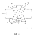
- Figs. 11 and 12 are diagrams showing a state during the operation of the robot hand RH1.
- Fig. 11 shows a state in which the robot hand RH1 grips a spherical body R1 as an object.
- Fig. 12 shows a state in which the robot hand RH1 grips a columnar member R2 as an object.
- the columnar member R2 include a tool having a columnar shape (e.g., a driver), a material having a columnar shape (e.g., a slim wire material, a piping tube of rubber or resin, or an electric wire).
- the object may be a tabular member (e.g., a thin plate) instead of the columnar member.
- the four finger units 201 to 204 are arranged in positions each rotated 90 degrees with respect to the predetermined position P.
- the first finger unit 201 and the third finger unit 203 are set to be opposed to each other and the second finger unit 202 and the fourth finger unit 204 are set to be opposed to each other across the predetermined position P. This makes it possible to stably hold the object.
- the tool R2 is arranged to pass through the center of the finger units 201 to 204.
- the first finger unit 201 and the fourth finger unit 204 are set to be opposed to each other and the second finger unit 202 and the third finger unit 203 are set to be opposed to each other across the predetermined position P (the first finger unit 201 and the second finger unit 202 are closed and the third finger unit 203 and the fourth finger unit 204 are closed). This makes it possible to stably hold the object.
- Figs. 13A to 13C are plan views showing operation for changing a direction in which an opening and closing action of the first finger unit 201, the second finger unit 202, the third finger unit 203, and the fourth finger unit 204 included in the robot hand RH1 (simultaneous driving of the four fingers) is performed.
- the operation performed when the first finger unit 201 and the second finger unit 202 (the third finger unit 203 and the fourth finger unit 204) rotate from a direction in which the finger units are apart from each other to a direction in which the finger units move close to each other is explained as an example.
- the distal end of the first finger unit 201 and the distal end of the second finger unit 202 are arranged in positions far from each other.
- the distal end of the third finger unit 203 and the distal end of the fourth finger unit 204 are also arranged in positions far from each other.
- a worm wheel 231 rotates and a worm 233 rotates in association with the rotation of the worm wheel 231.
- a first gear 241 rotates clockwise about a rotating shaft thereof in association with the rotation of the worm 233
- a second gear 242 rotates counterclockwise about a rotating shaft thereof in association with the rotation of the worm 233.
- a third gear 243 rotates clockwise about a rotating shaft thereof in association with the rotation of the worm 233 and a fourth gear 244 rotates counterclockwise about a rotating shaft thereof in association with the rotation of the worm 233.
- the first gear 241 further rotates clockwise about the rotating shaft in association with the rotation of the worm 233 and the second gear 242 further rotates counterclockwise about the Z axis in association with the rotation of the worm 233.
- the third gear 243 further rotates clockwise about the rotating shaft in association with the rotation of the worm 233 and the fourth gear 244 further rotates counterclockwise about the Z axis in association with the rotation of the worm 233.
- the two finger units 201 and 202 (the two finger units 203 and 204) rotate from the direction in which the finger units are apart from each other to the direction in which the finger units move close to each other. Consequently, for example, before the rotation of the motor, the finger units 201 to 204 can be arranged an equal space apart from one another about the predetermined position P.
- the first finger unit 201 and the fourth finger unit 204 can be set opposed to each other across the predetermined position P and the second finger unit 202 and the third finger unit 203 can be set opposed to each other across the predetermined position P (the first finger unit 201 and the second finger unit 202 are closed and the third finger unit 203 and the fourth finger unit 204 are closed).
- Fig. 14 is a plan view showing operation for changing the direction in which the opening and closing action of the first finger unit 201, and the second finger unit 202, the third finger unit 203, and the fourth finger unit 204 included in the robot hand RH1 is performed (independent driving for each two fingers).
- the first finger unit 201 and the second finger unit 202 can be rotated by a first worm wheel 231A and a first worm 233A.
- the third finger unit 203 and the fourth finger unit 204 can be rotated by a second worm wheel 231B and a second worm 233B. Consequently, the first and second finger units 201 and 202 and the third and fourth finger units 203 and 204 can be independently driven separately.
- the configuration of the robot hand RH1 including the four finger units 201 to 204 is explained as an example.
- the configuration of the robot hand RH1 is not limited to this.
- a robot hand may include five or more finger units. With this configuration, it is easy to grip a heavier object.
Landscapes
- Engineering & Computer Science (AREA)
- Robotics (AREA)
- Mechanical Engineering (AREA)
- Manipulator (AREA)
Claims (14)
- Roboterhand, mit:drei oder mehr Fingereinheiten, einschließlich einer ersten Fingereinheit (103, 201) und einer zweiten Fingereinheit (104, 202);einer Antriebseinheit (ACT), die bewirkt, dass die drei oder mehr Fingereinheiten, einen Öffnungs- und Schließvorgang ausführen; undeinem Fingereinheitsbewegungsmechanismus (130), der eine Richtung ändert, in welcher der Öffnungs- und Schließvorgang der ersten Fingereinheit (103, 201) und der zweiten Fingereinheit (104, 202) ausgeführt wird, wobeider Fingereinheitsbewegungsmechanismus (130) aufweist:eine Schneckenwelle (131, 231);einen Motor (132), der die Schneckenwelle (131, 231) dreht; undein Schneckenrad (133, 233), das sich in Verbindung mit der Drehung des Schneckenwelle (131, 231) in einer, von der Drehrichtung der Schneckenwelle (131, 231) verschiedenen Richtung dreht, wobeiein erstes Zahnrad (141, 241), das sich in Verbindung mit der Drehung des Schneckenrads (133, 233) in einer, von der Drehrichtung des Schneckenrads (133, 233) verschiedenen Richtung dreht, in der ersten Fingereinheit (103, 201) vorgesehen ist und ein zweites Zahnrad (141, 242), das sich in Verbindung mit der Drehung des Schneckenrads (133, 233) in einer Richtung entgegengesetzt zur Drehrichtung des ersten Zahnrads (141, 241) dreht, in der zweiten Fingereinheit (104, 202) vorgesehen ist, undsich die erste Fingereinheit (103, 201) und die zweite Fingereinheit (104, 202), in eine Richtung, in der sich die Fingereinheiten dicht zueinander hin bewegen oder in eine Richtung, in der sich die Fingereinheiten voneinander weg bewegen, drehen, wenn sich der Motor (132) dreht.
- Roboterhand nach Anspruch 1, wobei ein Raum zwischen einer drehenden Achse des ersten Zahnrades (141, 241) und einer drehenden Achse des zweiten Zahnrades (142, 242) gleich gehalten wird.
- Roboterhand nach Anspruch 1, wobei,
ein Drehwinkel unter dem sich das erste Zahnrad (141, 241) dreht und die erste Fingereinheit (103, 201) dreht, und ein Drehwinkel unter dem sich das zweite Zahnrad (142, 242) dreht und die zweite Fingereinheit (104, 202) dreht, zueinander gleich sind, wenn sich das erste Zahnrad (141, 241) und das zweite Zahnrad (142, 242) mit der gleichen Drehzahl drehen. - Roboterhand nach Anspruch 1 oder 2, wobei
die drei oder mehr Fingereinheiten drei Fingereinheiten (102, 103, 104) aufweisen, und
der Fingereinheitsbewegungsmechanismus (130) eine Richtung ändert, in welcher der Öffnungs- und Schließvorgang von zwei Fingereinheiten (102, 103, 104) aus den drei Fingereinheiten, ausgeführt wird. - Roboterhand nach einem der vorhergehenden Ansprüche, wobei
die drei oder mehr Fingereinheiten vier oder mehr Fingereinheiten aufweisen. - Roboterhand nach Anspruch 1, ferner mit
einer Verbindungseinheit (CN), welche die einen Enden der drei oder mehr Fingereinheiten, verbindet, wobei
die Antriebseinheit (ACT) die Verbindungseinheit (CN) antreibt, um dadurch die drei oder mehr Fingereinheiten in Synchronisation zueinander in eine Richtung zu bewegen, in welche sich die Fingereinheiten dicht zueinander hin oder voneinander weg bewegen. - Roboterhand nach Anspruch 6, wobei
ein erstes Verbindungselement (124), das sich in Verbindung mit der Drehung des Schneckenrads (133, 233) in einer gleichen Richtung wie die Drehrichtung des ersten Zahnrads (141, 241) dreht, in einem Abschnitt der ersten Fingereinheit (103, 201) vorgesehen ist, welcher mit der Verbindungseinheit (CN) verbunden ist, und
ein zweites Verbindungselement (124), das sich in Verbindung mit der Drehung des Schneckenrads (133, 233) in einer gleichen Richtung wie die Drehrichtung des zweiten Zahnrads (142, 242) dreht, in einem Abschnitt der zweiten Fingereinheit (104, 202) vorgesehen ist, welcher mit der Verbindungseinheit (CN) verbunden ist. - Roboterhand nach Anspruch 6 oder 7; wobei
die Verbindungseinheit (CN) an einer Gewindestange (107) befestigt ist und sich gemäß einem Antrieb durch die Antriebseinheit (MTR) entlang der Gewindestange (107) bewegt, und
die erste Fingereinheit (103, 201) und die zweite Fingereinheit (104, 202) den Öffnungs- und Schließvorgang ausführen, wenn sich das erste Verbindungselement (124) und das zweite Verbindungselement (124) gemäß der Bewegung der Verbindungseinheit (CN), bewegen. - Roboterhand nach einem der Ansprüche 6 bis 8, wobei
eine Drehachse des ersten Zahnrades (141, 241) und eine Drehachse des ersten Verbindungselements (124) koaxial zueinander sind, und
eine Drehachse des zweiten Zahnrades (142, 242) und eine Drehachse des zweiten Verbindungselements (124) koaxial zueinander sind. - Roboterhand nach einem der vorhergehenden Ansprüche, wobei
die Antriebseinheit (MTR) die drei oder mehr Fingereinheiten aus zueinander verschiedenen Richtungen her dicht zueinander hin bewegt, und
die drei oder mehr Fingereinheiten in zueinander verschiedene Richtungen voneinander weg bewegt. - Roboterhand nach einem der vorhergehenden Ansprüche, wobei
zumindest eine Fingereinheit aus den drei oder mehr Fingereinheiten aufweist:ein Kontaktelement (111) mit einem gebogenen Abschnitt (111C) ;ein Halteelement (120), welches das Kontaktelement (111) in dem gebogenen Abschnitt (111C) drehbar hält; undein elastisches Element (113), welche das Kontaktelement (111) und das Halteelement (120) verbindet. - Roboterhand nach Anspruch 11, wobei
das Kontaktelement (111) in einer Richtung gebogen ist, in welche die Fingereinheit schließt. - Roboterhand nach einem der vorhergehenden Ansprüche, wobei
zumindest eine Fingereinheit aus den drei oder mehr Fingereinheiten einen Anschlag (117) aufweist, der einen Drehwinkel der Drehung des Kontaktelements (111) reguliert. - Robotervorrichtung (RA), welche die Roboterhand nach einem der vorhergehenden Ansprüche aufweist.
Applications Claiming Priority (1)
| Application Number | Priority Date | Filing Date | Title |
|---|---|---|---|
| JP2011028574A JP2012166297A (ja) | 2011-02-14 | 2011-02-14 | ロボットハンド及びロボット装置 |
Publications (2)
| Publication Number | Publication Date |
|---|---|
| EP2487010A1 EP2487010A1 (de) | 2012-08-15 |
| EP2487010B1 true EP2487010B1 (de) | 2014-06-11 |
Family
ID=45571450
Family Applications (1)
| Application Number | Title | Priority Date | Filing Date |
|---|---|---|---|
| EP12154851.5A Not-in-force EP2487010B1 (de) | 2011-02-14 | 2012-02-10 | Roboterhand und Robotervorrichtung |
Country Status (4)
| Country | Link |
|---|---|
| US (1) | US8585111B2 (de) |
| EP (1) | EP2487010B1 (de) |
| JP (1) | JP2012166297A (de) |
| CN (1) | CN102632507B (de) |
Families Citing this family (86)
| Publication number | Priority date | Publication date | Assignee | Title |
|---|---|---|---|---|
| GB0409548D0 (en) * | 2004-04-29 | 2004-06-02 | King S College London | Robotic hand |
| JP5929215B2 (ja) | 2012-01-17 | 2016-06-01 | セイコーエプソン株式会社 | ロボットハンド及びロボット装置 |
| JP2014076522A (ja) * | 2012-10-11 | 2014-05-01 | Seiko Epson Corp | ロボットハンド及びロボット装置 |
| JP6111589B2 (ja) * | 2012-10-11 | 2017-04-12 | セイコーエプソン株式会社 | ロボットハンド、ロボット装置及びロボットハンドの製造方法 |
| US9004559B2 (en) | 2012-11-09 | 2015-04-14 | Irobot Corporation | Compliant underactuated grasper |
| EP2735408B1 (de) * | 2012-11-27 | 2016-04-20 | FESTO AG & Co. KG | Greifeinrichtung zum Greifen von Objekten |
| CN103395067B (zh) * | 2013-07-31 | 2016-01-13 | 北京航空航天大学 | 一种空间在轨服务机器人的自适应指爪机构 |
| US20150151433A1 (en) * | 2013-12-02 | 2015-06-04 | Harris Corporation | Compact robotic gripper |
| JPWO2015173879A1 (ja) * | 2014-05-13 | 2017-04-20 | 株式会社安川電機 | リード矯正装置、実装システム、基板製造方法 |
| JP2016049593A (ja) * | 2014-08-29 | 2016-04-11 | Thk株式会社 | アクチュエータ及びこのアクチュエータを用いたロボットハンド並びに歩行ロボット |
| CN104669290A (zh) * | 2014-08-29 | 2015-06-03 | 北京精密机电控制设备研究所 | 一种欠驱动空间机械臂末端执行器 |
| EP3838512A1 (de) | 2014-09-17 | 2021-06-23 | Soft Robotics, Inc. | Verstärkte weiche roboteraktoren |
| JP6775502B2 (ja) * | 2014-11-18 | 2020-10-28 | ソフト ロボティクス, インコーポレイテッド | ソフトロボットアクチュエータの向上 |
| US10189168B2 (en) | 2014-11-18 | 2019-01-29 | Soft Robotics, Inc. | Soft robotic actuator enhancements |
| US9486927B1 (en) | 2015-05-20 | 2016-11-08 | Google Inc. | Robotic gripper with multiple pairs of gripping fingers |
| WO2016201418A1 (en) * | 2015-06-11 | 2016-12-15 | Soft Robotics, Inc. | Modular robotic systems |
| CN104908056B (zh) * | 2015-06-29 | 2016-09-21 | 哈尔滨工业大学 | 一种可变构型的三指机械手爪 |
| CN105108770B (zh) * | 2015-09-17 | 2016-08-24 | 苏州博众精工科技有限公司 | 一种抓取装置 |
| CN105150235B (zh) * | 2015-09-18 | 2017-03-01 | 山东科技大学 | 一种绳驱动三指灵巧手 |
| US9744677B2 (en) | 2015-11-05 | 2017-08-29 | Irobot Corporation | Robotic fingers and end effectors including same |
| US9844885B2 (en) * | 2015-11-27 | 2017-12-19 | Tamkang University | Gripping device having opened and closed gripping modes |
| KR101776818B1 (ko) | 2016-02-29 | 2017-09-11 | 한국기술교육대학교 산학협력단 | 리스트유닛을 포함하는 로봇 핸드 어셈블리 |
| CN107243919A (zh) * | 2016-03-07 | 2017-10-13 | 温州市科泓机器人科技有限公司 | 自适应灵巧型机械手 |
| CN105835051B (zh) * | 2016-04-26 | 2018-06-12 | 江南大学 | 双电机驱动协同控制的欠驱动机械手 |
| CN105835081B (zh) * | 2016-04-26 | 2018-01-19 | 江南大学 | 刚柔耦合可转位手指的欠驱动机械手 |
| CN105818142A (zh) * | 2016-05-27 | 2016-08-03 | 新昌县城关新胜轴承厂 | 一种电动式抓物机械手 |
| CN105922281B (zh) * | 2016-05-28 | 2017-12-22 | 徐州市柯瑞斯电机制造有限公司 | 一种轻型六轴通用机器人的机械手组件 |
| CN106003118A (zh) * | 2016-06-01 | 2016-10-12 | 先驱智能机械(深圳)有限公司 | 吸取式机械手及机器人 |
| CN105881573B (zh) * | 2016-06-08 | 2017-08-25 | 佛山市夏云智能装备有限公司 | 一种通用机器人的机械手组件 |
| CN105880909B (zh) * | 2016-06-08 | 2018-06-08 | 泉州市家园网信息科技有限公司 | 一种焊接夹具夹紧头 |
| CN105904451B (zh) * | 2016-06-08 | 2018-03-20 | 孙美玲 | 一种机器人的机械手组件 |
| CN106041976A (zh) * | 2016-06-24 | 2016-10-26 | 先驱智能机械(深圳)有限公司 | 吸取式机械手及机器人 |
| CN106625734B (zh) * | 2016-09-28 | 2019-04-02 | 东北农业大学 | 一种针对异形瓜果仿鸟类爪部的欠驱动柔性末端执行器 |
| JP6426685B2 (ja) | 2016-12-16 | 2018-11-21 | ファナック株式会社 | ロボットに取り付けられる把持装置 |
| KR101932336B1 (ko) | 2017-04-11 | 2018-12-24 | 한국과학기술원 | 그리퍼 |
| CN108724239A (zh) * | 2017-04-21 | 2018-11-02 | 新加坡国立大学 | 柔性机械手 |
| CN107139206B (zh) * | 2017-05-17 | 2020-06-09 | 巢湖学院 | 一种可变姿态垃圾捡拾末端执行器 |
| JP7289616B2 (ja) * | 2017-06-30 | 2023-06-12 | キヤノン株式会社 | ロボットハンド、ロボット装置、ロボットハンドの制御方法 |
| CN107214729B (zh) * | 2017-07-11 | 2020-04-07 | 中南大学 | 一种具有多功能抓取的柔性气动机械手 |
| JP1605294S (de) * | 2017-07-18 | 2019-11-25 | ||
| USD847243S1 (en) * | 2017-07-18 | 2019-04-30 | Mitsubishi Electric Corporation | Manipulator for robot |
| JP1605291S (de) * | 2017-07-18 | 2019-11-25 | ||
| USD852859S1 (en) | 2017-07-18 | 2019-07-02 | Mitsubishi Electric Corporation | Manipulator for robot |
| USD846615S1 (en) * | 2017-07-18 | 2019-04-23 | Mitsubishi Electric Corporation | Manipulator for robot |
| JP1605292S (de) * | 2017-07-18 | 2019-11-25 | ||
| CN107322623A (zh) * | 2017-08-15 | 2017-11-07 | 中国地质大学(北京) | 一种用于精确抓取的三指自定心电动机械手爪 |
| KR102009311B1 (ko) * | 2017-10-13 | 2019-10-21 | 네이버랩스 주식회사 | 로봇 핸드 |
| JP6342567B1 (ja) * | 2017-11-16 | 2018-06-13 | シナノケンシ株式会社 | カム型ハンド機構 |
| DE102017220999B4 (de) * | 2017-11-23 | 2019-07-04 | Deutsches Zentrum für Luft- und Raumfahrt e.V. | Modularer Endeffektor |
| CN107972051A (zh) * | 2017-11-29 | 2018-05-01 | 清华大学 | 限位杆系增速补偿直线平夹自适应机器人手指装置 |
| JP6995602B2 (ja) * | 2017-12-14 | 2022-01-14 | キヤノン株式会社 | ロボットハンド、ロボットハンドの制御方法、ロボット装置、物品の製造方法、制御プログラムおよび記録媒体 |
| CN107932548A (zh) * | 2017-12-25 | 2018-04-20 | 无锡特恒科技有限公司 | 一种通过中轴和黄铜套摩擦的旋转机构 |
| JP7002326B2 (ja) * | 2017-12-26 | 2022-01-20 | 川崎重工業株式会社 | 蓋閉じ装置及び蓋閉じ方法 |
| JP6680757B2 (ja) * | 2017-12-28 | 2020-04-15 | ファナック株式会社 | 把持用ハンド |
| CN108382477A (zh) * | 2018-02-10 | 2018-08-10 | 郑州大学 | 一种适用于桁架结构的仿尺蠖攀爬机器人 |
| CN108247627B (zh) * | 2018-03-06 | 2024-07-02 | 苏州钧舵机器人有限公司 | 一种微型离合结构及具有该离合结构的机械手 |
| JP1613980S (de) * | 2018-03-29 | 2020-03-09 | ||
| JP1613032S (de) * | 2018-03-29 | 2020-03-02 | ||
| US12103180B2 (en) * | 2018-05-13 | 2024-10-01 | Robotiq Inc. | Robotic gripper |
| CN108656146B (zh) * | 2018-05-29 | 2020-11-10 | 北京航空航天大学 | 一种连续转动多功能三指机械手爪 |
| JP6836559B2 (ja) * | 2018-09-07 | 2021-03-03 | ファナック株式会社 | ロボットハンド |
| WO2020075414A1 (ja) * | 2018-10-09 | 2020-04-16 | アダマンド並木精密宝石株式会社 | ロボットハンド |
| CN109048981A (zh) * | 2018-10-23 | 2018-12-21 | 江门市众鑫表面处理有限公司 | 一种三爪机械手 |
| CN109202944A (zh) * | 2018-10-24 | 2019-01-15 | 武汉理工大学 | 一种用于汽车转向节的机器人打磨末端抓手 |
| JP2020084237A (ja) * | 2018-11-20 | 2020-06-04 | アイシン精機株式会社 | チャック装置 |
| CN109648590B (zh) * | 2019-01-31 | 2025-01-07 | 陕西伟景机器人科技有限公司 | 一种挤压传动的机械手 |
| JP7085736B2 (ja) * | 2019-02-28 | 2022-06-17 | 国立大学法人東北大学 | ロボットハンド |
| WO2020190164A1 (en) | 2019-03-19 | 2020-09-24 | Obshchestvo S Ogranichennoy Otvetstvennostyu "Tra Robotics" | Gripper device for a robotic arm capable of operating in two grasp modes |
| US11738893B2 (en) | 2019-04-30 | 2023-08-29 | Soft Robotics, Inc. | Picking, placing, and scanning bagged clothing and other articles |
| CN110509253B (zh) * | 2019-08-28 | 2020-08-07 | 南京驭逡通信科技有限公司 | 一种用于抓取靶向药物的微纳机器人 |
| CN110561481B (zh) * | 2019-10-12 | 2024-07-12 | 航天晨光股份有限公司 | 一种圆形物料机械抓取系统 |
| CN110994458B (zh) * | 2019-12-21 | 2021-07-20 | 陕西同力智慧能源服务有限公司 | 一种电力工程用鸟巢摘除工具 |
| KR102583215B1 (ko) * | 2020-01-30 | 2023-09-27 | 한국기술교육대학교 산학협력단 | 핑거 어셈블리 및 이를 포함하는 로봇핸드 |
| CN111421566A (zh) * | 2020-05-22 | 2020-07-17 | 西安建筑科技大学 | 一种皮带式欠驱动三关节机械手指结构及其操作方法 |
| EP4197717A4 (de) * | 2020-10-22 | 2024-03-13 | Samsung Electronics Co., Ltd. | Greifvorrichtung und robotervorrichtung damit |
| CN113021392B (zh) * | 2021-03-26 | 2022-04-22 | 中煤科工集团重庆研究院有限公司 | 一种矿用内置活塞式机械爪 |
| KR102436103B1 (ko) * | 2021-04-01 | 2022-08-25 | 경남대학교 산학협력단 | 다기능 그리퍼 |
| US11826910B2 (en) * | 2021-05-20 | 2023-11-28 | Carnegie Mellon University | Direct drive end-effectors with parallel kinematics |
| US11999055B2 (en) * | 2021-08-09 | 2024-06-04 | United States Of America, As Represented By The Secretary Of The Navy | Robotic grip device |
| CN114227748B (zh) * | 2022-01-25 | 2023-10-27 | 深圳市万至达电机制造有限公司 | 用于抓取球状物品的电动机械爪及其夹持物品的判断方法 |
| KR102788081B1 (ko) * | 2022-10-31 | 2025-03-31 | 한국과학기술연구원 | 가변 구조형 로봇 손바닥을 갖는 로봇 핸드 |
| ES2977940A1 (es) * | 2023-01-23 | 2024-09-03 | Consejo Superior Investigacion | Garra robotica para agarre y manipulacion |
| CN116728439A (zh) * | 2023-06-06 | 2023-09-12 | 颖态智能技术(上海)有限公司 | 一种筒形机械抓手装置 |
| KR102896290B1 (ko) * | 2023-11-08 | 2025-12-05 | 주식회사 알파로보틱스 | 다품종 그리퍼 |
| DE102024120962A1 (de) * | 2024-07-24 | 2026-01-29 | Schaeffler Technologies AG & Co. KG | Greifeinrichtung, insbesondere Roboterhand, für einen Roboterarm mit mindestens zwei bewegbaren Fingern und mindestens einer Antriebseinheit zum Bereitstellen einer Antriebskraft zum Bewegen der Finger und ein Verfahren |
| CN118990570B (zh) * | 2024-08-21 | 2025-10-21 | 浙江灵巧智能科技有限公司 | 一种多自由度大拇指机构 |
Family Cites Families (30)
| Publication number | Priority date | Publication date | Assignee | Title |
|---|---|---|---|---|
| US3901547A (en) * | 1973-05-14 | 1975-08-26 | Ii Frank R Skinner | Multiple prehension mechanism |
| JPS50148784A (de) | 1974-05-21 | 1975-11-28 | ||
| EP0000877B1 (de) | 1977-08-31 | 1983-05-18 | Grisebach, Hans-Theodor | Manipulator zum Positionieren von Werkstücken oder anderen Lasten |
| CA1114856A (en) | 1977-09-20 | 1981-12-22 | Hans T. Grisebach | Manipulator |
| JPS6025686A (ja) | 1983-07-20 | 1985-02-08 | 株式会社東芝 | ロボツトハンド |
| JPS63201086A (ja) | 1987-02-13 | 1988-08-19 | Nippon Telegr & Teleph Corp <Ntt> | 単結晶成長法 |
| US5108140A (en) * | 1988-04-18 | 1992-04-28 | Odetics, Inc. | Reconfigurable end effector |
| US5501498A (en) * | 1988-08-31 | 1996-03-26 | The Trustees Of The University Of Pennsylvania | Methods and apparatus for mechanically intelligent grasping |
| US4957320A (en) * | 1988-08-31 | 1990-09-18 | Trustees Of The University Of Pennsylvania | Methods and apparatus for mechanically intelligent grasping |
| US5172951A (en) * | 1990-08-06 | 1992-12-22 | University Of Utah Research Foundation | Robotic grasping apparatus |
| JPH0744475Y2 (ja) * | 1992-08-12 | 1995-10-11 | 株式会社中央製作所 | チャック |
| JPH0725454A (ja) * | 1993-07-09 | 1995-01-27 | Shibuya Kogyo Co Ltd | クランプ式容器搬送装置 |
| JP3317799B2 (ja) | 1994-11-28 | 2002-08-26 | 宇宙開発事業団 | マニピュレータの把持装置 |
| US5762390A (en) * | 1996-07-16 | 1998-06-09 | Universite Laval | Underactuated mechanical finger with return actuation |
| US6244644B1 (en) * | 1999-01-25 | 2001-06-12 | The United States Of America As Represented By The Administrator Of The National Aeronautics And Space Administration | Compact dexterous robotic hand |
| JP2000288971A (ja) | 1999-04-01 | 2000-10-17 | Souki Sekkei:Kk | ロボットハンド |
| JP4104038B2 (ja) * | 2000-03-08 | 2008-06-18 | 株式会社小松製作所 | 把持装置 |
| US6505870B1 (en) | 2000-05-30 | 2003-01-14 | UNIVERSITé LAVAL | Actuation system for highly underactuated gripping mechanism |
| KR100451412B1 (ko) * | 2001-11-09 | 2004-10-06 | 한국과학기술연구원 | 다지 로봇 핸드 |
| JP2007516854A (ja) * | 2003-12-30 | 2007-06-28 | ストライダー ラブス,インコーポレイテッド | 伸縮式の手のひらを有するロボットハンド |
| JP4876796B2 (ja) | 2006-08-30 | 2012-02-15 | 株式会社不二越 | 産業用ロボットのハンド装置 |
| JP4918004B2 (ja) * | 2006-11-24 | 2012-04-18 | パナソニック株式会社 | 多指ロボットハンド |
| JP2009113195A (ja) * | 2007-10-19 | 2009-05-28 | Tokyo Univ Of Science | 関節装置 |
| JP2010036256A (ja) | 2008-07-31 | 2010-02-18 | Meiwa E Tec:Kk | 把持装置 |
| JP5263945B2 (ja) * | 2008-09-17 | 2013-08-14 | 株式会社レクザム | ダブルアーム型ロボット |
| WO2010064708A1 (ja) | 2008-12-04 | 2010-06-10 | 川崎重工業株式会社 | ロボットハンド |
| JP5243233B2 (ja) | 2008-12-26 | 2013-07-24 | 川崎重工業株式会社 | ロボットハンド |
| CN201357413Y (zh) * | 2009-03-02 | 2009-12-09 | 杭州电子科技大学 | 一种夹紧机械手爪 |
| KR101674894B1 (ko) * | 2009-12-21 | 2016-11-10 | 삼성전자 주식회사 | 산업용 다자유도 그리퍼 |
| JP2011161577A (ja) | 2010-02-10 | 2011-08-25 | Seiko Epson Corp | ロボットハンド及びロボット装置 |
-
2011
- 2011-02-14 JP JP2011028574A patent/JP2012166297A/ja active Pending
-
2012
- 2012-02-01 CN CN201210022573.5A patent/CN102632507B/zh not_active Expired - Fee Related
- 2012-02-10 EP EP12154851.5A patent/EP2487010B1/de not_active Not-in-force
- 2012-02-13 US US13/371,771 patent/US8585111B2/en not_active Expired - Fee Related
Also Published As
| Publication number | Publication date |
|---|---|
| CN102632507A (zh) | 2012-08-15 |
| CN102632507B (zh) | 2016-09-07 |
| US8585111B2 (en) | 2013-11-19 |
| JP2012166297A (ja) | 2012-09-06 |
| US20120205932A1 (en) | 2012-08-16 |
| EP2487010A1 (de) | 2012-08-15 |
Similar Documents
| Publication | Publication Date | Title |
|---|---|---|
| EP2487010B1 (de) | Roboterhand und Robotervorrichtung | |
| JP5929215B2 (ja) | ロボットハンド及びロボット装置 | |
| CN103507076B (zh) | 机器人手、机器人、以及把持机构 | |
| CN103991082B (zh) | 机器手 | |
| US8690213B2 (en) | Robot hand and robot | |
| CN109476023B (zh) | 可变刚度串联式弹性致动器 | |
| WO2018008491A1 (en) | Parallel link device, industrial robot, and haptic presentation device | |
| CN101823261B (zh) | 一种机器人手爪结构 | |
| TW200902259A (en) | Robot and control method | |
| JP2009006460A (ja) | ロボットハンド | |
| JP2016068192A (ja) | ロボットハンド及びロボット | |
| WO2013014720A1 (ja) | パラレルリンクロボット | |
| US11389952B2 (en) | Robot arm | |
| WO2018033716A1 (en) | An Improved Gripper | |
| JP2011062788A (ja) | マニピュレータ装置およびマニピュレータの制御方法 | |
| JP2011161577A (ja) | ロボットハンド及びロボット装置 | |
| JP2019141957A (ja) | ロボットハンドおよびロボット | |
| WO2021107900A1 (en) | A three finger robotic gripper design with spherical mechanism | |
| JP7189531B2 (ja) | リンク作動装置 | |
| JP7802555B2 (ja) | グリッパ及びロボット | |
| JP7022964B2 (ja) | ロボットハンドの把持方法 | |
| CN201872172U (zh) | 一种用于夹持工件的传动结构 | |
| JP2026501987A (ja) | 把持装置 | |
| JP2019034388A (ja) | 把持装置 | |
| WO2019065425A1 (ja) | ロボットハンドおよびロボットハンド制御方法 |
Legal Events
| Date | Code | Title | Description |
|---|---|---|---|
| PUAI | Public reference made under article 153(3) epc to a published international application that has entered the european phase |
Free format text: ORIGINAL CODE: 0009012 |
|
| AK | Designated contracting states |
Kind code of ref document: A1 Designated state(s): AL AT BE BG CH CY CZ DE DK EE ES FI FR GB GR HR HU IE IS IT LI LT LU LV MC MK MT NL NO PL PT RO RS SE SI SK SM TR |
|
| AX | Request for extension of the european patent |
Extension state: BA ME |
|
| 17P | Request for examination filed |
Effective date: 20130207 |
|
| GRAP | Despatch of communication of intention to grant a patent |
Free format text: ORIGINAL CODE: EPIDOSNIGR1 |
|
| INTG | Intention to grant announced |
Effective date: 20140121 |
|
| GRAS | Grant fee paid |
Free format text: ORIGINAL CODE: EPIDOSNIGR3 |
|
| GRAA | (expected) grant |
Free format text: ORIGINAL CODE: 0009210 |
|
| AK | Designated contracting states |
Kind code of ref document: B1 Designated state(s): AL AT BE BG CH CY CZ DE DK EE ES FI FR GB GR HR HU IE IS IT LI LT LU LV MC MK MT NL NO PL PT RO RS SE SI SK SM TR |
|
| REG | Reference to a national code |
Ref country code: GB Ref legal event code: FG4D |
|
| REG | Reference to a national code |
Ref country code: CH Ref legal event code: EP |
|
| REG | Reference to a national code |
Ref country code: IE Ref legal event code: FG4D |
|
| REG | Reference to a national code |
Ref country code: AT Ref legal event code: REF Ref document number: 672012 Country of ref document: AT Kind code of ref document: T Effective date: 20140715 |
|
| REG | Reference to a national code |
Ref country code: DE Ref legal event code: R096 Ref document number: 602012002008 Country of ref document: DE Effective date: 20140724 |
|
| PG25 | Lapsed in a contracting state [announced via postgrant information from national office to epo] |
Ref country code: NO Free format text: LAPSE BECAUSE OF FAILURE TO SUBMIT A TRANSLATION OF THE DESCRIPTION OR TO PAY THE FEE WITHIN THE PRESCRIBED TIME-LIMIT Effective date: 20140911 Ref country code: GR Free format text: LAPSE BECAUSE OF FAILURE TO SUBMIT A TRANSLATION OF THE DESCRIPTION OR TO PAY THE FEE WITHIN THE PRESCRIBED TIME-LIMIT Effective date: 20140912 Ref country code: FI Free format text: LAPSE BECAUSE OF FAILURE TO SUBMIT A TRANSLATION OF THE DESCRIPTION OR TO PAY THE FEE WITHIN THE PRESCRIBED TIME-LIMIT Effective date: 20140611 Ref country code: LT Free format text: LAPSE BECAUSE OF FAILURE TO SUBMIT A TRANSLATION OF THE DESCRIPTION OR TO PAY THE FEE WITHIN THE PRESCRIBED TIME-LIMIT Effective date: 20140611 |
|
| REG | Reference to a national code |
Ref country code: NL Ref legal event code: VDEP Effective date: 20140611 |
|
| REG | Reference to a national code |
Ref country code: AT Ref legal event code: MK05 Ref document number: 672012 Country of ref document: AT Kind code of ref document: T Effective date: 20140611 |
|
| REG | Reference to a national code |
Ref country code: LT Ref legal event code: MG4D |
|
| PG25 | Lapsed in a contracting state [announced via postgrant information from national office to epo] |
Ref country code: SE Free format text: LAPSE BECAUSE OF FAILURE TO SUBMIT A TRANSLATION OF THE DESCRIPTION OR TO PAY THE FEE WITHIN THE PRESCRIBED TIME-LIMIT Effective date: 20140611 Ref country code: RS Free format text: LAPSE BECAUSE OF FAILURE TO SUBMIT A TRANSLATION OF THE DESCRIPTION OR TO PAY THE FEE WITHIN THE PRESCRIBED TIME-LIMIT Effective date: 20140611 Ref country code: HR Free format text: LAPSE BECAUSE OF FAILURE TO SUBMIT A TRANSLATION OF THE DESCRIPTION OR TO PAY THE FEE WITHIN THE PRESCRIBED TIME-LIMIT Effective date: 20140611 Ref country code: LV Free format text: LAPSE BECAUSE OF FAILURE TO SUBMIT A TRANSLATION OF THE DESCRIPTION OR TO PAY THE FEE WITHIN THE PRESCRIBED TIME-LIMIT Effective date: 20140611 |
|
| PG25 | Lapsed in a contracting state [announced via postgrant information from national office to epo] |
Ref country code: SK Free format text: LAPSE BECAUSE OF FAILURE TO SUBMIT A TRANSLATION OF THE DESCRIPTION OR TO PAY THE FEE WITHIN THE PRESCRIBED TIME-LIMIT Effective date: 20140611 Ref country code: CZ Free format text: LAPSE BECAUSE OF FAILURE TO SUBMIT A TRANSLATION OF THE DESCRIPTION OR TO PAY THE FEE WITHIN THE PRESCRIBED TIME-LIMIT Effective date: 20140611 Ref country code: RO Free format text: LAPSE BECAUSE OF FAILURE TO SUBMIT A TRANSLATION OF THE DESCRIPTION OR TO PAY THE FEE WITHIN THE PRESCRIBED TIME-LIMIT Effective date: 20140611 Ref country code: ES Free format text: LAPSE BECAUSE OF FAILURE TO SUBMIT A TRANSLATION OF THE DESCRIPTION OR TO PAY THE FEE WITHIN THE PRESCRIBED TIME-LIMIT Effective date: 20140611 Ref country code: EE Free format text: LAPSE BECAUSE OF FAILURE TO SUBMIT A TRANSLATION OF THE DESCRIPTION OR TO PAY THE FEE WITHIN THE PRESCRIBED TIME-LIMIT Effective date: 20140611 Ref country code: PT Free format text: LAPSE BECAUSE OF FAILURE TO SUBMIT A TRANSLATION OF THE DESCRIPTION OR TO PAY THE FEE WITHIN THE PRESCRIBED TIME-LIMIT Effective date: 20141013 |
|
| PG25 | Lapsed in a contracting state [announced via postgrant information from national office to epo] |
Ref country code: AT Free format text: LAPSE BECAUSE OF FAILURE TO SUBMIT A TRANSLATION OF THE DESCRIPTION OR TO PAY THE FEE WITHIN THE PRESCRIBED TIME-LIMIT Effective date: 20140611 Ref country code: NL Free format text: LAPSE BECAUSE OF FAILURE TO SUBMIT A TRANSLATION OF THE DESCRIPTION OR TO PAY THE FEE WITHIN THE PRESCRIBED TIME-LIMIT Effective date: 20140611 Ref country code: PL Free format text: LAPSE BECAUSE OF FAILURE TO SUBMIT A TRANSLATION OF THE DESCRIPTION OR TO PAY THE FEE WITHIN THE PRESCRIBED TIME-LIMIT Effective date: 20140611 Ref country code: IS Free format text: LAPSE BECAUSE OF FAILURE TO SUBMIT A TRANSLATION OF THE DESCRIPTION OR TO PAY THE FEE WITHIN THE PRESCRIBED TIME-LIMIT Effective date: 20141011 |
|
| REG | Reference to a national code |
Ref country code: DE Ref legal event code: R097 Ref document number: 602012002008 Country of ref document: DE |
|
| PLBE | No opposition filed within time limit |
Free format text: ORIGINAL CODE: 0009261 |
|
| STAA | Information on the status of an ep patent application or granted ep patent |
Free format text: STATUS: NO OPPOSITION FILED WITHIN TIME LIMIT |
|
| PG25 | Lapsed in a contracting state [announced via postgrant information from national office to epo] |
Ref country code: DK Free format text: LAPSE BECAUSE OF FAILURE TO SUBMIT A TRANSLATION OF THE DESCRIPTION OR TO PAY THE FEE WITHIN THE PRESCRIBED TIME-LIMIT Effective date: 20140611 Ref country code: IT Free format text: LAPSE BECAUSE OF FAILURE TO SUBMIT A TRANSLATION OF THE DESCRIPTION OR TO PAY THE FEE WITHIN THE PRESCRIBED TIME-LIMIT Effective date: 20140611 |
|
| 26N | No opposition filed |
Effective date: 20150312 |
|
| REG | Reference to a national code |
Ref country code: DE Ref legal event code: R097 Ref document number: 602012002008 Country of ref document: DE Effective date: 20150312 |
|
| PG25 | Lapsed in a contracting state [announced via postgrant information from national office to epo] |
Ref country code: BE Free format text: LAPSE BECAUSE OF FAILURE TO SUBMIT A TRANSLATION OF THE DESCRIPTION OR TO PAY THE FEE WITHIN THE PRESCRIBED TIME-LIMIT Effective date: 20140611 |
|
| PG25 | Lapsed in a contracting state [announced via postgrant information from national office to epo] |
Ref country code: SI Free format text: LAPSE BECAUSE OF FAILURE TO SUBMIT A TRANSLATION OF THE DESCRIPTION OR TO PAY THE FEE WITHIN THE PRESCRIBED TIME-LIMIT Effective date: 20140611 |
|
| PG25 | Lapsed in a contracting state [announced via postgrant information from national office to epo] |
Ref country code: LU Free format text: LAPSE BECAUSE OF FAILURE TO SUBMIT A TRANSLATION OF THE DESCRIPTION OR TO PAY THE FEE WITHIN THE PRESCRIBED TIME-LIMIT Effective date: 20150210 |
|
| REG | Reference to a national code |
Ref country code: CH Ref legal event code: PL |
|
| PG25 | Lapsed in a contracting state [announced via postgrant information from national office to epo] |
Ref country code: CH Free format text: LAPSE BECAUSE OF NON-PAYMENT OF DUE FEES Effective date: 20150228 Ref country code: LI Free format text: LAPSE BECAUSE OF NON-PAYMENT OF DUE FEES Effective date: 20150228 Ref country code: MC Free format text: LAPSE BECAUSE OF FAILURE TO SUBMIT A TRANSLATION OF THE DESCRIPTION OR TO PAY THE FEE WITHIN THE PRESCRIBED TIME-LIMIT Effective date: 20140611 |
|
| REG | Reference to a national code |
Ref country code: IE Ref legal event code: MM4A |
|
| REG | Reference to a national code |
Ref country code: FR Ref legal event code: ST Effective date: 20151030 |
|
| PG25 | Lapsed in a contracting state [announced via postgrant information from national office to epo] |
Ref country code: IE Free format text: LAPSE BECAUSE OF NON-PAYMENT OF DUE FEES Effective date: 20150210 |
|
| PG25 | Lapsed in a contracting state [announced via postgrant information from national office to epo] |
Ref country code: FR Free format text: LAPSE BECAUSE OF NON-PAYMENT OF DUE FEES Effective date: 20150302 |
|
| PG25 | Lapsed in a contracting state [announced via postgrant information from national office to epo] |
Ref country code: MT Free format text: LAPSE BECAUSE OF FAILURE TO SUBMIT A TRANSLATION OF THE DESCRIPTION OR TO PAY THE FEE WITHIN THE PRESCRIBED TIME-LIMIT Effective date: 20140611 |
|
| PG25 | Lapsed in a contracting state [announced via postgrant information from national office to epo] |
Ref country code: BG Free format text: LAPSE BECAUSE OF FAILURE TO SUBMIT A TRANSLATION OF THE DESCRIPTION OR TO PAY THE FEE WITHIN THE PRESCRIBED TIME-LIMIT Effective date: 20140611 Ref country code: SM Free format text: LAPSE BECAUSE OF FAILURE TO SUBMIT A TRANSLATION OF THE DESCRIPTION OR TO PAY THE FEE WITHIN THE PRESCRIBED TIME-LIMIT Effective date: 20140611 Ref country code: HU Free format text: LAPSE BECAUSE OF FAILURE TO SUBMIT A TRANSLATION OF THE DESCRIPTION OR TO PAY THE FEE WITHIN THE PRESCRIBED TIME-LIMIT; INVALID AB INITIO Effective date: 20120210 |
|
| PG25 | Lapsed in a contracting state [announced via postgrant information from national office to epo] |
Ref country code: CY Free format text: LAPSE BECAUSE OF FAILURE TO SUBMIT A TRANSLATION OF THE DESCRIPTION OR TO PAY THE FEE WITHIN THE PRESCRIBED TIME-LIMIT Effective date: 20140611 |
|
| PG25 | Lapsed in a contracting state [announced via postgrant information from national office to epo] |
Ref country code: TR Free format text: LAPSE BECAUSE OF FAILURE TO SUBMIT A TRANSLATION OF THE DESCRIPTION OR TO PAY THE FEE WITHIN THE PRESCRIBED TIME-LIMIT Effective date: 20140611 |
|
| PG25 | Lapsed in a contracting state [announced via postgrant information from national office to epo] |
Ref country code: MK Free format text: LAPSE BECAUSE OF FAILURE TO SUBMIT A TRANSLATION OF THE DESCRIPTION OR TO PAY THE FEE WITHIN THE PRESCRIBED TIME-LIMIT Effective date: 20140611 |
|
| PG25 | Lapsed in a contracting state [announced via postgrant information from national office to epo] |
Ref country code: AL Free format text: LAPSE BECAUSE OF FAILURE TO SUBMIT A TRANSLATION OF THE DESCRIPTION OR TO PAY THE FEE WITHIN THE PRESCRIBED TIME-LIMIT Effective date: 20140611 |
|
| PGFP | Annual fee paid to national office [announced via postgrant information from national office to epo] |
Ref country code: DE Payment date: 20200129 Year of fee payment: 9 Ref country code: GB Payment date: 20200129 Year of fee payment: 9 |
|
| REG | Reference to a national code |
Ref country code: DE Ref legal event code: R119 Ref document number: 602012002008 Country of ref document: DE |
|
| GBPC | Gb: european patent ceased through non-payment of renewal fee |
Effective date: 20210210 |
|
| PG25 | Lapsed in a contracting state [announced via postgrant information from national office to epo] |
Ref country code: GB Free format text: LAPSE BECAUSE OF NON-PAYMENT OF DUE FEES Effective date: 20210210 Ref country code: DE Free format text: LAPSE BECAUSE OF NON-PAYMENT OF DUE FEES Effective date: 20210901 |