EP2484748A1 - Nukleinsäureanalysegerät - Google Patents
Nukleinsäureanalysegerät Download PDFInfo
- Publication number
- EP2484748A1 EP2484748A1 EP10820619A EP10820619A EP2484748A1 EP 2484748 A1 EP2484748 A1 EP 2484748A1 EP 10820619 A EP10820619 A EP 10820619A EP 10820619 A EP10820619 A EP 10820619A EP 2484748 A1 EP2484748 A1 EP 2484748A1
- Authority
- EP
- European Patent Office
- Prior art keywords
- nucleic acid
- chip
- oil
- reaction containers
- specimen
- Prior art date
- Legal status (The legal status is an assumption and is not a legal conclusion. Google has not performed a legal analysis and makes no representation as to the accuracy of the status listed.)
- Granted
Links
- 108020004707 nucleic acids Proteins 0.000 title claims abstract description 316
- 102000039446 nucleic acids Human genes 0.000 title claims abstract description 316
- 150000007523 nucleic acids Chemical class 0.000 title claims abstract description 316
- 238000004458 analytical method Methods 0.000 claims abstract description 165
- 238000006243 chemical reaction Methods 0.000 claims abstract description 136
- 239000007788 liquid Substances 0.000 claims abstract description 80
- 238000001821 nucleic acid purification Methods 0.000 claims abstract description 46
- 238000000746 purification Methods 0.000 claims abstract description 30
- 238000011282 treatment Methods 0.000 claims abstract description 26
- 239000007795 chemical reaction product Substances 0.000 claims abstract description 4
- 239000003153 chemical reaction reagent Substances 0.000 claims description 100
- 238000000605 extraction Methods 0.000 claims description 55
- 239000000243 solution Substances 0.000 claims description 55
- 239000000463 material Substances 0.000 claims description 33
- 238000002347 injection Methods 0.000 claims description 28
- 239000007924 injection Substances 0.000 claims description 28
- 230000007246 mechanism Effects 0.000 claims description 21
- 238000007789 sealing Methods 0.000 claims description 20
- 230000003287 optical effect Effects 0.000 claims description 16
- 239000002699 waste material Substances 0.000 claims description 16
- 230000005284 excitation Effects 0.000 claims description 9
- 230000008859 change Effects 0.000 claims description 8
- 239000011347 resin Substances 0.000 claims description 7
- 229920005989 resin Polymers 0.000 claims description 7
- 239000002250 absorbent Substances 0.000 claims description 5
- 230000002745 absorbent Effects 0.000 claims description 5
- 238000002955 isolation Methods 0.000 claims description 5
- 239000007769 metal material Substances 0.000 claims description 5
- 239000003921 oil Substances 0.000 description 40
- 238000000034 method Methods 0.000 description 35
- 108090000623 proteins and genes Proteins 0.000 description 24
- 238000001179 sorption measurement Methods 0.000 description 24
- 230000035772 mutation Effects 0.000 description 21
- 239000000523 sample Substances 0.000 description 21
- 239000010408 film Substances 0.000 description 19
- 230000032258 transport Effects 0.000 description 16
- 238000003752 polymerase chain reaction Methods 0.000 description 15
- 230000008569 process Effects 0.000 description 13
- 210000004602 germ cell Anatomy 0.000 description 12
- 238000012360 testing method Methods 0.000 description 12
- 238000005406 washing Methods 0.000 description 10
- 210000004027 cell Anatomy 0.000 description 9
- 210000000078 claw Anatomy 0.000 description 8
- 230000002093 peripheral effect Effects 0.000 description 7
- -1 polypropylene Polymers 0.000 description 7
- 101710113436 GTPase KRas Proteins 0.000 description 6
- 238000005842 biochemical reaction Methods 0.000 description 6
- 238000005259 measurement Methods 0.000 description 6
- 239000003129 oil well Substances 0.000 description 6
- 239000012620 biological material Substances 0.000 description 5
- 239000008280 blood Substances 0.000 description 5
- 210000004369 blood Anatomy 0.000 description 5
- 238000001514 detection method Methods 0.000 description 5
- 230000000694 effects Effects 0.000 description 5
- 102000016928 DNA-directed DNA polymerase Human genes 0.000 description 4
- 108010014303 DNA-directed DNA polymerase Proteins 0.000 description 4
- VYPSYNLAJGMNEJ-UHFFFAOYSA-N Silicium dioxide Chemical compound O=[Si]=O VYPSYNLAJGMNEJ-UHFFFAOYSA-N 0.000 description 4
- 239000003814 drug Substances 0.000 description 4
- 229940079593 drug Drugs 0.000 description 4
- 239000013307 optical fiber Substances 0.000 description 4
- 239000004743 Polypropylene Substances 0.000 description 3
- 230000009471 action Effects 0.000 description 3
- 239000012472 biological sample Substances 0.000 description 3
- 230000004048 modification Effects 0.000 description 3
- 238000012986 modification Methods 0.000 description 3
- 239000002773 nucleotide Substances 0.000 description 3
- 125000003729 nucleotide group Chemical group 0.000 description 3
- 229920001155 polypropylene Polymers 0.000 description 3
- 108700042226 ras Genes Proteins 0.000 description 3
- RYGMFSIKBFXOCR-UHFFFAOYSA-N Copper Chemical compound [Cu] RYGMFSIKBFXOCR-UHFFFAOYSA-N 0.000 description 2
- 102000004190 Enzymes Human genes 0.000 description 2
- 108090000790 Enzymes Proteins 0.000 description 2
- 102000013446 GTP Phosphohydrolases Human genes 0.000 description 2
- 108091006109 GTPases Proteins 0.000 description 2
- PXHVJJICTQNCMI-UHFFFAOYSA-N Nickel Chemical compound [Ni] PXHVJJICTQNCMI-UHFFFAOYSA-N 0.000 description 2
- 108091034117 Oligonucleotide Proteins 0.000 description 2
- BQCADISMDOOEFD-UHFFFAOYSA-N Silver Chemical compound [Ag] BQCADISMDOOEFD-UHFFFAOYSA-N 0.000 description 2
- PPBRXRYQALVLMV-UHFFFAOYSA-N Styrene Chemical compound C=CC1=CC=CC=C1 PPBRXRYQALVLMV-UHFFFAOYSA-N 0.000 description 2
- 229910052782 aluminium Inorganic materials 0.000 description 2
- XAGFODPZIPBFFR-UHFFFAOYSA-N aluminium Chemical compound [Al] XAGFODPZIPBFFR-UHFFFAOYSA-N 0.000 description 2
- 238000011109 contamination Methods 0.000 description 2
- 229910052802 copper Inorganic materials 0.000 description 2
- 239000010949 copper Substances 0.000 description 2
- 210000000805 cytoplasm Anatomy 0.000 description 2
- PCHJSUWPFVWCPO-UHFFFAOYSA-N gold Chemical compound [Au] PCHJSUWPFVWCPO-UHFFFAOYSA-N 0.000 description 2
- 239000010931 gold Substances 0.000 description 2
- 229910052737 gold Inorganic materials 0.000 description 2
- 239000010781 infectious medical waste Substances 0.000 description 2
- 102000054765 polymorphisms of proteins Human genes 0.000 description 2
- 239000011148 porous material Substances 0.000 description 2
- 239000000377 silicon dioxide Substances 0.000 description 2
- 229910052709 silver Inorganic materials 0.000 description 2
- 239000004332 silver Substances 0.000 description 2
- JHPBZFOKBAGZBL-UHFFFAOYSA-N (3-hydroxy-2,2,4-trimethylpentyl) 2-methylprop-2-enoate Chemical compound CC(C)C(O)C(C)(C)COC(=O)C(C)=C JHPBZFOKBAGZBL-UHFFFAOYSA-N 0.000 description 1
- 229910001369 Brass Inorganic materials 0.000 description 1
- 108091006027 G proteins Proteins 0.000 description 1
- 102000030782 GTP binding Human genes 0.000 description 1
- 108091000058 GTP-Binding Proteins 0.000 description 1
- 201000003741 Gastrointestinal carcinoma Diseases 0.000 description 1
- VVQNEPGJFQJSBK-UHFFFAOYSA-N Methyl methacrylate Chemical compound COC(=O)C(C)=C VVQNEPGJFQJSBK-UHFFFAOYSA-N 0.000 description 1
- 206010028980 Neoplasm Diseases 0.000 description 1
- 108700019961 Neoplasm Genes Proteins 0.000 description 1
- 102000048850 Neoplasm Genes Human genes 0.000 description 1
- 108091028043 Nucleic acid sequence Proteins 0.000 description 1
- 206010061902 Pancreatic neoplasm Diseases 0.000 description 1
- 239000004698 Polyethylene Substances 0.000 description 1
- XUIMIQQOPSSXEZ-UHFFFAOYSA-N Silicon Chemical compound [Si] XUIMIQQOPSSXEZ-UHFFFAOYSA-N 0.000 description 1
- 241000700605 Viruses Species 0.000 description 1
- 230000001133 acceleration Effects 0.000 description 1
- 238000003556 assay Methods 0.000 description 1
- 230000015572 biosynthetic process Effects 0.000 description 1
- 239000010951 brass Substances 0.000 description 1
- 201000011510 cancer Diseases 0.000 description 1
- 210000000170 cell membrane Anatomy 0.000 description 1
- 108010041758 cleavase Proteins 0.000 description 1
- 238000004040 coloring Methods 0.000 description 1
- 229920001577 copolymer Polymers 0.000 description 1
- 238000012864 cross contamination Methods 0.000 description 1
- 238000013461 design Methods 0.000 description 1
- 238000011161 development Methods 0.000 description 1
- 238000009792 diffusion process Methods 0.000 description 1
- 238000006073 displacement reaction Methods 0.000 description 1
- 230000036267 drug metabolism Effects 0.000 description 1
- 239000000428 dust Substances 0.000 description 1
- 238000006911 enzymatic reaction Methods 0.000 description 1
- 239000002657 fibrous material Substances 0.000 description 1
- 239000011491 glass wool Substances 0.000 description 1
- 230000005484 gravity Effects 0.000 description 1
- 125000002887 hydroxy group Chemical group [H]O* 0.000 description 1
- 230000002401 inhibitory effect Effects 0.000 description 1
- 201000002313 intestinal cancer Diseases 0.000 description 1
- 208000015486 malignant pancreatic neoplasm Diseases 0.000 description 1
- 229910052751 metal Inorganic materials 0.000 description 1
- 239000002184 metal Substances 0.000 description 1
- 239000002480 mineral oil Substances 0.000 description 1
- 235000010446 mineral oil Nutrition 0.000 description 1
- 238000002156 mixing Methods 0.000 description 1
- 239000000178 monomer Substances 0.000 description 1
- 229910052759 nickel Inorganic materials 0.000 description 1
- 239000011368 organic material Substances 0.000 description 1
- 201000002528 pancreatic cancer Diseases 0.000 description 1
- 208000008443 pancreatic carcinoma Diseases 0.000 description 1
- 239000002245 particle Substances 0.000 description 1
- 230000035515 penetration Effects 0.000 description 1
- 239000002985 plastic film Substances 0.000 description 1
- 229920006255 plastic film Polymers 0.000 description 1
- 229920003229 poly(methyl methacrylate) Polymers 0.000 description 1
- 229920000515 polycarbonate Polymers 0.000 description 1
- 239000004417 polycarbonate Substances 0.000 description 1
- 229920000573 polyethylene Polymers 0.000 description 1
- 239000004926 polymethyl methacrylate Substances 0.000 description 1
- 229920005629 polypropylene homopolymer Polymers 0.000 description 1
- 238000002360 preparation method Methods 0.000 description 1
- 239000013615 primer Substances 0.000 description 1
- 239000002987 primer (paints) Substances 0.000 description 1
- 229920005604 random copolymer Polymers 0.000 description 1
- 210000005132 reproductive cell Anatomy 0.000 description 1
- 150000003839 salts Chemical class 0.000 description 1
- 230000035945 sensitivity Effects 0.000 description 1
- 239000010703 silicon Substances 0.000 description 1
- 229910052710 silicon Inorganic materials 0.000 description 1
- 238000005245 sintering Methods 0.000 description 1
- 230000006641 stabilisation Effects 0.000 description 1
- 238000011105 stabilization Methods 0.000 description 1
- 239000010409 thin film Substances 0.000 description 1
- 238000002834 transmittance Methods 0.000 description 1
Images


Classifications
-
- G—PHYSICS
- G01—MEASURING; TESTING
- G01N—INVESTIGATING OR ANALYSING MATERIALS BY DETERMINING THEIR CHEMICAL OR PHYSICAL PROPERTIES
- G01N21/00—Investigating or analysing materials by the use of optical means, i.e. using sub-millimetre waves, infrared, visible or ultraviolet light
- G01N21/62—Systems in which the material investigated is excited whereby it emits light or causes a change in wavelength of the incident light
- G01N21/63—Systems in which the material investigated is excited whereby it emits light or causes a change in wavelength of the incident light optically excited
- G01N21/64—Fluorescence; Phosphorescence
- G01N21/645—Specially adapted constructive features of fluorimeters
- G01N21/6452—Individual samples arranged in a regular 2D-array, e.g. multiwell plates
-
- B—PERFORMING OPERATIONS; TRANSPORTING
- B01—PHYSICAL OR CHEMICAL PROCESSES OR APPARATUS IN GENERAL
- B01L—CHEMICAL OR PHYSICAL LABORATORY APPARATUS FOR GENERAL USE
- B01L3/00—Containers or dishes for laboratory use, e.g. laboratory glassware; Droppers
- B01L3/50—Containers for the purpose of retaining a material to be analysed, e.g. test tubes
- B01L3/508—Containers for the purpose of retaining a material to be analysed, e.g. test tubes rigid containers not provided for above
- B01L3/5082—Test tubes per se
- B01L3/50825—Closing or opening means, corks, bungs
-
- G—PHYSICS
- G01—MEASURING; TESTING
- G01N—INVESTIGATING OR ANALYSING MATERIALS BY DETERMINING THEIR CHEMICAL OR PHYSICAL PROPERTIES
- G01N21/00—Investigating or analysing materials by the use of optical means, i.e. using sub-millimetre waves, infrared, visible or ultraviolet light
- G01N21/01—Arrangements or apparatus for facilitating the optical investigation
- G01N21/03—Cuvette constructions
- G01N21/07—Centrifugal type cuvettes
-
- G—PHYSICS
- G01—MEASURING; TESTING
- G01N—INVESTIGATING OR ANALYSING MATERIALS BY DETERMINING THEIR CHEMICAL OR PHYSICAL PROPERTIES
- G01N35/00—Automatic analysis not limited to methods or materials provided for in any single one of groups G01N1/00 - G01N33/00; Handling materials therefor
- G01N35/02—Automatic analysis not limited to methods or materials provided for in any single one of groups G01N1/00 - G01N33/00; Handling materials therefor using a plurality of sample containers moved by a conveyor system past one or more treatment or analysis stations
- G01N35/04—Details of the conveyor system
-
- B—PERFORMING OPERATIONS; TRANSPORTING
- B01—PHYSICAL OR CHEMICAL PROCESSES OR APPARATUS IN GENERAL
- B01L—CHEMICAL OR PHYSICAL LABORATORY APPARATUS FOR GENERAL USE
- B01L2200/00—Solutions for specific problems relating to chemical or physical laboratory apparatus
- B01L2200/06—Fluid handling related problems
- B01L2200/0615—Loss of fluid by dripping
-
- B—PERFORMING OPERATIONS; TRANSPORTING
- B01—PHYSICAL OR CHEMICAL PROCESSES OR APPARATUS IN GENERAL
- B01L—CHEMICAL OR PHYSICAL LABORATORY APPARATUS FOR GENERAL USE
- B01L2200/00—Solutions for specific problems relating to chemical or physical laboratory apparatus
- B01L2200/06—Fluid handling related problems
- B01L2200/0673—Handling of plugs of fluid surrounded by immiscible fluid
-
- B—PERFORMING OPERATIONS; TRANSPORTING
- B01—PHYSICAL OR CHEMICAL PROCESSES OR APPARATUS IN GENERAL
- B01L—CHEMICAL OR PHYSICAL LABORATORY APPARATUS FOR GENERAL USE
- B01L2200/00—Solutions for specific problems relating to chemical or physical laboratory apparatus
- B01L2200/06—Fluid handling related problems
- B01L2200/0689—Sealing
-
- B—PERFORMING OPERATIONS; TRANSPORTING
- B01—PHYSICAL OR CHEMICAL PROCESSES OR APPARATUS IN GENERAL
- B01L—CHEMICAL OR PHYSICAL LABORATORY APPARATUS FOR GENERAL USE
- B01L2200/00—Solutions for specific problems relating to chemical or physical laboratory apparatus
- B01L2200/14—Process control and prevention of errors
- B01L2200/141—Preventing contamination, tampering
-
- B—PERFORMING OPERATIONS; TRANSPORTING
- B01—PHYSICAL OR CHEMICAL PROCESSES OR APPARATUS IN GENERAL
- B01L—CHEMICAL OR PHYSICAL LABORATORY APPARATUS FOR GENERAL USE
- B01L2300/00—Additional constructional details
- B01L2300/04—Closures and closing means
- B01L2300/041—Connecting closures to device or container
- B01L2300/044—Connecting closures to device or container pierceable, e.g. films, membranes
-
- B—PERFORMING OPERATIONS; TRANSPORTING
- B01—PHYSICAL OR CHEMICAL PROCESSES OR APPARATUS IN GENERAL
- B01L—CHEMICAL OR PHYSICAL LABORATORY APPARATUS FOR GENERAL USE
- B01L2300/00—Additional constructional details
- B01L2300/08—Geometry, shape and general structure
- B01L2300/0803—Disc shape
-
- B—PERFORMING OPERATIONS; TRANSPORTING
- B01—PHYSICAL OR CHEMICAL PROCESSES OR APPARATUS IN GENERAL
- B01L—CHEMICAL OR PHYSICAL LABORATORY APPARATUS FOR GENERAL USE
- B01L2300/00—Additional constructional details
- B01L2300/18—Means for temperature control
- B01L2300/1805—Conductive heating, heat from thermostatted solids is conducted to receptacles, e.g. heating plates, blocks
-
- B—PERFORMING OPERATIONS; TRANSPORTING
- B01—PHYSICAL OR CHEMICAL PROCESSES OR APPARATUS IN GENERAL
- B01L—CHEMICAL OR PHYSICAL LABORATORY APPARATUS FOR GENERAL USE
- B01L3/00—Containers or dishes for laboratory use, e.g. laboratory glassware; Droppers
- B01L3/50—Containers for the purpose of retaining a material to be analysed, e.g. test tubes
- B01L3/508—Containers for the purpose of retaining a material to be analysed, e.g. test tubes rigid containers not provided for above
- B01L3/5085—Containers for the purpose of retaining a material to be analysed, e.g. test tubes rigid containers not provided for above for multiple samples, e.g. microtitration plates
- B01L3/50851—Containers for the purpose of retaining a material to be analysed, e.g. test tubes rigid containers not provided for above for multiple samples, e.g. microtitration plates specially adapted for heating or cooling samples
-
- G—PHYSICS
- G01—MEASURING; TESTING
- G01N—INVESTIGATING OR ANALYSING MATERIALS BY DETERMINING THEIR CHEMICAL OR PHYSICAL PROPERTIES
- G01N21/00—Investigating or analysing materials by the use of optical means, i.e. using sub-millimetre waves, infrared, visible or ultraviolet light
- G01N21/01—Arrangements or apparatus for facilitating the optical investigation
- G01N21/03—Cuvette constructions
- G01N2021/0325—Cells for testing reactions, e.g. containing reagents
-
- G—PHYSICS
- G01—MEASURING; TESTING
- G01N—INVESTIGATING OR ANALYSING MATERIALS BY DETERMINING THEIR CHEMICAL OR PHYSICAL PROPERTIES
- G01N35/00—Automatic analysis not limited to methods or materials provided for in any single one of groups G01N1/00 - G01N33/00; Handling materials therefor
- G01N2035/00346—Heating or cooling arrangements
- G01N2035/00356—Holding samples at elevated temperature (incubation)
-
- G—PHYSICS
- G01—MEASURING; TESTING
- G01N—INVESTIGATING OR ANALYSING MATERIALS BY DETERMINING THEIR CHEMICAL OR PHYSICAL PROPERTIES
- G01N35/00—Automatic analysis not limited to methods or materials provided for in any single one of groups G01N1/00 - G01N33/00; Handling materials therefor
- G01N35/02—Automatic analysis not limited to methods or materials provided for in any single one of groups G01N1/00 - G01N33/00; Handling materials therefor using a plurality of sample containers moved by a conveyor system past one or more treatment or analysis stations
- G01N35/04—Details of the conveyor system
- G01N2035/046—General conveyor features
-
- G—PHYSICS
- G01—MEASURING; TESTING
- G01N—INVESTIGATING OR ANALYSING MATERIALS BY DETERMINING THEIR CHEMICAL OR PHYSICAL PROPERTIES
- G01N35/00—Automatic analysis not limited to methods or materials provided for in any single one of groups G01N1/00 - G01N33/00; Handling materials therefor
- G01N35/10—Devices for transferring samples or any liquids to, in, or from, the analysis apparatus, e.g. suction devices, injection devices
- G01N2035/1027—General features of the devices
- G01N2035/103—General features of the devices using disposable tips
-
- G—PHYSICS
- G01—MEASURING; TESTING
- G01N—INVESTIGATING OR ANALYSING MATERIALS BY DETERMINING THEIR CHEMICAL OR PHYSICAL PROPERTIES
- G01N35/00—Automatic analysis not limited to methods or materials provided for in any single one of groups G01N1/00 - G01N33/00; Handling materials therefor
- G01N35/00029—Automatic analysis not limited to methods or materials provided for in any single one of groups G01N1/00 - G01N33/00; Handling materials therefor provided with flat sample substrates, e.g. slides
- G01N35/00069—Automatic analysis not limited to methods or materials provided for in any single one of groups G01N1/00 - G01N33/00; Handling materials therefor provided with flat sample substrates, e.g. slides whereby the sample substrate is of the bio-disk type, i.e. having the format of an optical disk
-
- G—PHYSICS
- G01—MEASURING; TESTING
- G01N—INVESTIGATING OR ANALYSING MATERIALS BY DETERMINING THEIR CHEMICAL OR PHYSICAL PROPERTIES
- G01N35/00—Automatic analysis not limited to methods or materials provided for in any single one of groups G01N1/00 - G01N33/00; Handling materials therefor
- G01N35/0099—Automatic analysis not limited to methods or materials provided for in any single one of groups G01N1/00 - G01N33/00; Handling materials therefor comprising robots or similar manipulators
Definitions
- the present invention relates to a nucleic acid analyzer.
- Priority is claimed on Japanese Patent Application No. 2009-228809, filed September 30, 2009 , the content of which is incorporated herein by reference.
- Single nucleotide polymorphisms are polymorphism that includes mutations at a single base within a DNA sequence formed of a plurality of bases. It has been known that differences in such nucleotide sequence cause personal differences in, for example, drug metabolism and the like.
- nucleic acid is extracted from a specimen such as a biological sample taken from, for example, a patient, and differences in a gene such as SNPs are detected.
- sensitivity to medicines can be predicted in advance by differences in genes. Accordingly, it is considered that a so-called tailor-made medical treatment (which is also referred to as order-made medical treatment) will be realized, which provides the optimum medical treatment (drug) for each patient while reducing the side effects of medicines.
- a nucleic acid analyzer which supplies a whole blood sample taken from a patient to a cartridge and purifies and analyzes nucleic acid using the cartridge, is disclosed in, for example, Patent Document 1 as a device that performs this gene test. According to the nucleic acid analyzer disclosed in Patent Document 1, it is possible to reduce a user's workload on the nucleic acid analysis by reducing the dependence on a user's manual work. In addition, it is possible to increase the reproducibility of the nucleic acid analysis without variations in the collection rate for nucleic acid that is caused by differences in the users' skill.
- a gene detection-determination device which can measure a plurality of SNPs at one time by forming a plurality of reaction chambers used to measure a plurality of SNPs, is disclosed in Patent Document 2. According to this gene detection-determination device, it is possible to suppress the occurrence of human errors or contamination and to increase the accuracy of a gene test.
- the invention has been made in consideration of the above-mentioned circumstances, and an object of the invention is to provide a nucleic acid analyzer that can easily perform an accurate gene test.
- the invention proposes the followings in order to achieve the object.
- nucleic acid analyzer of the invention since processes from the purification of nucleic acid to the analysis of nucleic acid can be automatically performed, it is possible to easily perform an accurate gene test.
- FIG. 1 is a perspective view showing the appearance of the nucleic acid analyzer 1 according to this embodiment.
- FIG. 2 is a plan view showing the structure of a part of the nucleic acid analyzer 1.
- the nucleic acid analyzer 1 automatically performs a series of operations that purify nucleic acid from a specimen, amplify a region of the purified nucleic acid including SNP (Single Nucleotide Polymorphisms) that is an object to be tested, and measure SNP of the amplified nucleic acid by the invader (registered trademark) method.
- SNP Single Nucleotide Polymorphisms
- the nucleic acid analyzer 1 is provided in, for example, a stationary housing 31.
- a terminal 2 is connected to the nucleic acid analyzer 1 through a signal line (not shown).
- the operation of a user can be input to the nucleic acid analyzer 1 by the terminal 2, or the results of the analysis of nucleic acid can be displayed on the terminal 2.
- the nucleic acid analyzer 1 includes a nucleic acid purification kit 10 that obtains a nucleic acid solution by isolating and purifying nucleic acid from a specimen; a nucleic acid analysis chip 20 that has a central axis (rotation axis) O positioned at the center thereof, includes a plurality of reaction containers 22 at the outer portion than the central axis O in a radial direction, and feeds the nucleic acid, which is purified by the nucleic acid purification kit 10, to the reaction containers 22 through centrifugal force around the central axis O; a specimen-introducing part 40 on which the nucleic acid purification kit 10 is placed; and an analyzer body 30.
- a nucleic acid purification kit 10 that obtains a nucleic acid solution by isolating and purifying nucleic acid from a specimen
- a nucleic acid analysis chip 20 that has a central axis (rotation axis) O positioned at the center thereof, includes a plurality of
- the nucleic acid purification kit 10 breaks down cells included in a specimen such as a biological sample, and isolates and purifies nucleic acid, which is included in the cells, by making the nucleic acid be adsorbed on a carrier.
- the nucleic acid analysis chip 20 performs a biochemical reaction on the nucleic acid that is purified by the nucleic acid purification kit 10.
- the nucleic acid purification kit 10 and the nucleic acid analysis chip 20 are disposed in the analyzer body 30, and the analyzer body performs a purification or analysis operation on the nucleic acid purification kit 10 and the nucleic acid analysis chip 20. Specifically, as shown in FIG.
- the analyzer body 30 includes an analysis chip holder 42 that is provided at the specimen-introducing part 40 and supports the nucleic acid analysis chip 20; a purification treatment unit 50 that isolates and purifies nucleic acid by the nucleic acid purification kit 10 and injects the nucleic acid solution containing the purified nucleic acid into the nucleic acid analysis chip 20; a centrifugal liquid feed unit 60 that feeds the nucleic acid solution to each of the reaction containers 22 by rotating the nucleic acid analysis chip 20 about the central axis O; an analysis unit 70 that analyzes reaction products in the reaction containers 22; and a transport unit (transport part) 55 that relatively transports the specimen-introducing part 40 to each of the purification treatment unit 50, the centrifugal liquid feed unit 60, and the analysis unit 70.
- an analysis chip holder 42 that is provided at the specimen-introducing part 40 and supports the nucleic acid analysis chip 20
- a purification treatment unit 50 that isolates and purifies nucleic acid by the nucleic acid purification kit 10 and injects the
- FIGS. 3 and 4 are perspective views showing the structure of the nucleic acid purification kit 10.
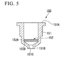
- FIG. 5 is a cross-sectional view showing the structure of an extraction filter cartridge 150 of the nucleic acid purification kit 10.
- FIG. 6A is an enlarged cross-sectional view showing the structure of an oil-removing unit 128 of the nucleic acid purification kit 10
- FIG. 6B is an exploded perspective view showing the structure of a wiper 129.
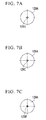
- FIGS. 7A, 7B, and FIG. 7C are plan views showing the structure of a part of the oil-removing unit 128.
- the nucleic acid purification kit 10 includes a reagent cartridge 100 in which a reagent or the like used to extract nucleic acid from a specimen is stored, and a dispensing chip rack (dispensing chip-receiver) 200 in which a plurality of dispensing chips (oil-dispensing chips and reagent-dispensing chips) 201 dispensing liquids are received.
- the dispensing chip rack 200 includes the plurality of dispensing chips 201.
- Liquids which are stored in the reagent cartridge 100, are dispensed or agitated by any one of the plurality of dispensing chips 201, so that cross-contamination does not occur between the liquids by the dispensing chips 201. Further, since the dispensing chip rack 200 is also a container in which the dispensing chips 201 having been used are collected, the dispensing chips 201 as infectious waste may be discarded from each dispensing chip rack 200 after the use of the dispensing chips 201 of the nucleic acid analyzer 1.
- the reagent cartridge 100 includes a body 101 that is formed in the shape of a box having an opening, and claw portions 102 that are formed so as to protrude laterally from the outer surface of the body 101.
- the claw portions 102 fix the reagent cartridge 100 to the specimen-introducing part 40 to be described below in the analyzer body 30.
- a filmy sealing film 103 to be removed at the time of the use of the nucleic acid purification kit 10 be attached to a part of the outer surface of the body 101.
- the opening of the body 101 is sealed by the sealing film 103. Accordingly, it is possible to prevent the extraction filter cartridge 150 and the like, which are disposed in the body 101 and will be described below, from falling from the body 101. In addition, it is possible to prevent foreign materials such as dust from entering the body 101.
- the reagent cartridge 100 includes the extraction filter cartridge 150 that contains a carrier adsorbing nucleic acid, and a holding portion 160 in which the extraction filter cartridge 150 is received is formed integrally with the reagent cartridge 100.
- the reagent well portion 120 includes a plurality of reagent wells (reagent storage portions) 121, 122, 123, 124, 125, and 126; an oil well (oil storage portion) 127; and the oil-removing unit 128. Further, at the reagent well portion 120, openings of the plurality of reagent wells 121, 122, 123, 124, 125, and 126 and an opening of the oil well 127 are sealed by a sealing film 104 shown in Fig. 3 . The penetration of gas to the body 101 is suppressed by the sealing film 104. Further, it is preferable that the sealing film 104 can be broken by being pierced by the dispensing chips 201. For example, a thin film made of metal, a plastic film, or the like may be used as the sealing film 104.
- an analytical reagent may be stored in a reagent well.
- analytical reagent premixes where a part of a reagent used to measure SNP of nucleic acid by PCR (Polymerase Chain Reaction) and the invader (registered trademark) method is previously mixed may be individually stored in the respective reagent wells.
- An analytical reagent premix is a mixed liquid that contains a base and a DNA polymerase for PCR, Cleavase (registered trademark) used in the invader (registered trademark) method, and a buffer used to perform PCR and a reaction using the invader (registered trademark) method together. It is preferable that the analytical reagent premix be stored in a reagent well so as to have a concentration higher than the optimum concentration at the time of a reaction in order to suppress enzyme activity while an analytical reagent premix is stored in a reagent well.
- oil 127A which is used while being superimposed on a reaction solution in a PCR reaction, is stored in the oil well 127.
- oil 127A for example, mineral oil, silicon oil, and the like may be preferably employed as the oil 127A.
- the oil-removing unit 128 include the wiper 129, which removes the oil 127A adhering to the outer surface of the dispensing chip 201 (see FIG. 4 ), therein as shown in FIG. 6A .
- the wiper 129 includes a wiping filter 129A that has a lipophilic property, and cylindrical support parts 129B and 129D that support the wiping filter 129A in the oil-removing unit 128.
- the wiping filter 129A is formed substantially in the shape of a column or a disc corresponding to the inner diameter of the oil-removing unit 128, and a slit 129C, which passes through the wiping filter in the direction of a central axis of the wiping filter 129A, is formed at the center of the wiping filter 129A.
- the slit 129C is positioned at the center of the wiping filter 129A and formed in a cross shape when seen in the direction of the central axis.
- the wiping filter 129A may include a slit 129E, which is formed in a true circular shape when the wiping filter 129A is seen in the direction of the central axis, instead of the slit 129C.
- the wiping filter 129A may include a circular slit 129F, which includes protruding portions protruding toward the inside in the radial direction of the wiping filter 129A, instead of the slit 129C.
- the waste liquid well 130 has a shape such that the extraction filter cartridge 150 can be supported at concave portions formed along the outer diameter shape of the extraction filter cartridge 150. While the extraction filter cartridge 150 is mounted in the waste liquid well 130, the extraction filter cartridge 150 does not fall down in the reagent cartridge 100.
- the collection well 140 has a shape such that the extraction filter cartridge 150 can be supported.
- the bottom portion of the collection well 140 has the shape of a container that can store a nucleic acid solution eluted from the carrier of the extraction filter cartridge 150 by the eluate 125A.
- the waste liquid well 130 and the collection well 140 are disposed in the reagent cartridge 100 so as to be adjacent to each other.
- the reason for this disposition is to reduce the movement of the extraction filter cartridge 150 when the extraction filter cartridge 150 is moved to the collection well 140 after the extraction filter cartridge 150 is washed in the waste liquid well 130. Accordingly, it is possible to reduce the possibility of the extraction filter cartridge 150 passing above the reagent cartridge 100 contaminating the reagent cartridge 100 and the like.
- the extraction filter cartridge 150 includes a substantially cylindrical body 151 that forms an outer frame of the extraction filter cartridge, and an extraction filter unit 152 that is provided in the body 151.
- the body 151 is formed in the shape of a funnel so that the diameter of an opening of a portion of the body 151, which is closer to the lower end 151B than the extraction filter unit 152, is smaller than the diameter of the opening of the upper end 151A.
- a nozzle-like discharge port 151C is formed at the lower end 151B so as to protrude downward.
- the eluate 125A, the washing solutions 123A and 124A, the solution 121A where a specimen is dissolved, and the like are supplied from the opening of the upper end 151A, pass through the filter unit 152, and are discharged from the discharge port 151C.
- the filter unit 152 includes an adsorption filter 152A that contains a carrier having a property to adsorb nucleic acid, and a support member 152B that is disposed closer to the lower end 151B than the adsorption filter 152A and prevents the adsorption filter 152A from being deformed.
- the adsorption filter 152A is made of a porous material capable of adsorbing nucleic acid and formed in the shape of a film. It is preferable that a material having a property to adsorb nucleic acid in the washing solutions 123A and 124A and adsorb less nucleic acid in the eluate 125A be used as the material of the adsorption filter 152A. Further, it is preferable that the adsorption filter 152A be made of a porous material to which a hydroxyl group is introduced as a hydrophilic group. Specifically, the adsorption filter 152A is made of silica or a material coated with silica.
- the material of the adsorption filter 152A is not particularly limited. Furthermore, the adsorption filter 152A is formed by superimposing fibrous materials such as glass wool, so that the adsorption filter 152A may have porosity.
- the support member 152B be made of a material having low adsorbability for at least nucleic acid and not inhibiting a reaction for extracting nucleic acid from a specimen.
- the support member 152B may be formed so as to have porosity by the sintering of resin particles.
- the rigidity of the support member 152B is higher than that of the adsorption filter 152A, so that the deformation of the adsorption filter 152A in the body 151 is suppressed by the support member 152B.
- an absorbent body (not shown), which absorbs liquid, be provided at the bottom portion of the holding portion 160 shown in FIG. 4 .
- the absorbent body comes into contact with the outer surface of the extraction filter cartridge 150 corresponding to the discharge port 151C. Accordingly, for example, when the washing solution 123A adheres to the outer surface of the discharge port 151C while the washing solution 123A is supplied to the extraction filter cartridge 150, it is possible to remove the washing solution 123A by making the washing solution 123A be absorbed in the absorbent body.
- the structure of the nucleic acid analysis chip 20 will be described below with reference to FIGS. 8A to 8C .
- the nucleic acid analysis chip 20 includes a disc-like chip body 21 and a lid body 29 that is attached to the chip body 21.
- the chip body 21 includes the plurality of reaction containers 22 that are arranged in the circumferential direction of the chip body 21 so as to be at the same distance from the center of the chip body 21, and passages 23 that are formed on the chip body 21 so as to communicate with each of the reaction containers 22.
- twenty-three reaction containers 22 are formed at the chip body 21.
- the material of the chip body 21 be a material not affecting the analysis of nucleic acid. Specifically, it is preferable that the material of the chip body 21 be a resin material containing at least one or more of polypropylene, polycarbonate, and acryl. Homopolypropylene or a random copolymer of polypropylene and polyethylene may be used as polypropylene. Further, a copolymer of polymethyl methacrylate or methyl methacrylate and a monomer such as other methacrylic ester, acrylic ester, or styrene may be used as acryl.
- the chip body 21 have optical transparency at the portions of at least the reaction container 22, and it is preferable that fluorescence, coloring, or the like generated by a biochemical reaction occurring in the reaction containers 22 be detectable from the outside of the reaction containers 22. Specifically, it is preferable that the chip body transmit light in a visible light region (wavelength is in the range of 350 nm to 780 nm) at a light transmittance of 70% or more. Moreover, the chip body 21 may be made of a resin material having optical transparency.
- the reaction containers 22 are formed at the chip body 21 as substantially hemispherical-concave portions that can store liquid therein.
- Reagents which are used to perform biochemical reactions, are provided on the inner wall surfaces of the reaction containers 22.
- at least a pair of primer sets that amplifies a gene region containing SNP, which is an object to be tested, and invader (registered trademark) oligos and signal probes that are used in the invader (registered trademark) method are received in each of the reaction containers 22.
- plural kinds of primer sets, invader (registered trademark) oligos, and signal probes which vary according to a gene region, that is, an object to be tested, be previously disposed in each of the reaction containers 22. In this case, it is possible to measure different kinds of SNPs for every reaction container 22. Further, according to, for example, the nucleic acid analysis chips 20 of this embodiment, it is possible to simultaneously measure twenty-three kinds of SNPs.
- each of the flow passages 23 includes a main flow passage 24 and a branch flow passage 25.
- the main flow passage 24 is formed so as to extend in the circumferential direction of the chip body 21 while meandering between the center of the chip body 21 and the outer portion of the chip body 21 in the radial direction.
- the branch flow passage 25 is branched from the main flow passage 24 so as to communicate with the main flow passage 24 and the reaction container 22.
- One end 24A of the main flow passage 24 communicates with the injection port 26, and the other end 24B of the main flow passage 24 communicates with the outlet 27. Further, the main flow passage 24 is formed between the reaction containers 22, which are adjacent to each other in the circumferential direction of the chip body 21, so as to have a chevron shape 24C that protrudes along the central axis O.
- main flow passage 24 is formed between the reaction containers 22 that are adjacent to each other in the circumferential direction of the chip body 21 and has a chevron shape 24C in the direction of the central axis O, liquid stored in the main flow passages 24 is interrupted at the apexes 24D of the chevron shapes 24C and fed to each of the reaction containers 22 when the nucleic acid analysis chip 20 is rotated about the central axis O.
- the branch flow passage 25 is formed so that the area of a portion of the branch flow passage connected to the main flow passage 24 is smaller than the area of the main flow passage 24.
- a portion of the branch flow passage 25 connected to the main flow passage 24 forms a flow restricting portion 25A that restricts the liquid flowing to the branch flow passage 25 from the main flow passage 24.
- the lid body 29 is provided on the side of the chip body 21 where the reaction containers 22 and the flow passages 23 are formed.
- the lid body 29 is attached to the chip body 21, so that concave portions forming the reaction containers 22 and the flow passages 23 are lidded. Accordingly, independent reaction spaces and flow passages are formed.
- the material of the lid body 29 be a material having high thermal conductivity.
- Metal materials such as aluminum, copper, silver, nickel, brass, and gold, may be employed as the material of the lid body 29.
- a portion having thermal conductivity may be at a portion of the lid body where at least reaction containers 22 are positioned.
- the lid body 29 may be formed of a thin plate made of the same resin material as the resin material of the above-mentioned chip body 21.
- the nucleic acid analysis chip 20 of this embodiment feeds liquid, which is stored in the main flow passages 24, to the respective branch flow passages 25 and feeds the liquid to each of the reaction containers 22 through the branch flow passages 25 through centrifugal force that is generated due to the rotation of the nucleic acid analysis chip 20 about the central axis O.
- the analyzer body 30 includes the specimen-introducing part 40 where the above-mentioned nucleic acid purification kit 10 and the above-mentioned nucleic acid analysis chip 20 are disposed, the purification treatment unit 50 that performs an operation for extracting nucleic acid from a specimen by the nucleic acid purification kit 10, the centrifugal liquid feed unit 60 that rotates the nucleic acid analysis chip 20 about the central axis O, and the analysis unit 70 that analyzes nucleic acid in the reaction containers 22 of the nucleic acid analysis chip 20.
- the specimen-introducing part 40 includes a tray 41 where the reagent cartridge 100 and the dispensing chip rack 200 of the nucleic acid purification kit 10 are disposed, and the analysis chip holder 42 where the nucleic acid analysis chip 20 is placed.
- the tray 41 Since the tray 41 is detachably mounted on the specimen-introducing part 40, the tray can be sterilized or discarded as infectious waste when a specimen or the like adheres to the tray. Further, since the tray 41 is provided with engagement portions 43 with which the above-mentioned claw portions 102 formed at the reagent cartridge 100 are engaged, the reagent cartridge 100 does not fall down on the tray 41. In this embodiment, the claw portions 102 serve as a positioning mechanism that positions the reagent cartridge 100 on the specimen-introducing part 40.
- the nucleic acid analysis chip 20 is fitted to a circular through-hole, so that the analysis chip holder 42 can support the nucleic acid analysis chip 20.
- the purification treatment unit 50 includes a dispensing section 52 that transports the dispensing chips 201 disposed in the dispensing chip rack 200 and sucks, holds, and discharges liquid by using a robot hand 51 and the dispensing chips 201; and a pressurizing section 53 that pressurizes the inner portion of the extraction filter cartridge 150 by making air flow into the extraction filter cartridge from the upper end of the extraction filter cartridge 150 received in the reagent cartridge 100.
- the dispensing chip 201 is detachably connected to the dispensing section 52 by press-fitting. In this state, liquid is dispensed or transferred by the dispensing chip 201 ( FIGS. 10 and 11 ). Further, the plurality of dispensing chips 201 are prepared, and are appropriately replaced to prevent contamination.
- the dispensing section 52 is provided with the release portion.
- a protruding portion which is easily engaged with the release portion, may be formed at the upper end of the dispensing chip 201.
- the extraction filter cartridge 150 is moved by the robot hand 51 and is pressurized by the pressurizing section 53. During this pressurization, the pressurizing section 53 and the extraction filter cartridge 150 can be air-tightly engaged with each other ( FIG. 12 ).
- Examples of the structure which is suitable for making the pressurizing section and the extraction filter cartridge be air-tightly engaged with each other, include a structure where an elastic member is provided at the lower end of the pressurizing section 53 or the upper end 151A of the extraction filter cartridge 150. It is possible to pressurize the inner portion of the extraction filter cartridge 150 by the pressurizing section 53 while the pressurizing section 53 and the extraction filter cartridge 150 are engaged as described above.
- a well-known centrifugal device may be appropriately employed as the centrifugal liquid feed unit 60, and the centrifugal liquid feed unit 60 can support the nucleic acid analysis chip 20 and rotate the nucleic acid analysis chip 20 about the central axis O. It is preferable that the rotational speed of the nucleic acid analysis chip 20 rotated by the centrifugal liquid feed unit 60 be substantially equal to a speed where liquid flows into the branch flow passages 25 from the main flow passages 24 through centrifugal force applied to the liquid supplied into the nucleic acid analysis chip 20. The optimum rotational speed of the nucleic acid analysis chip depends on the shape of the nucleic acid analysis chip. For example, in the case of the nucleic acid analysis chip 20 of this embodiment, it is preferable that the rotational speed of the nucleic acid analysis chip 20 rotated by the centrifugal liquid feed unit 60 be 1000 rpm or more.
- the analysis unit 70 includes a temperature control mechanism 80 that comes into contact with the nucleic acid analysis chip 20 and changes the temperature in the reaction container 22 of the nucleic acid analysis chip 20 so that the temperature in the reaction container 22 corresponds to a predetermined temperature change; and a fluorescence measuring section 90 that measures fluorescence in the reaction container 22 of the nucleic acid analysis chip 20.
- the temperature control mechanism 80 includes upper and lower heat plates 81 and 82 that have flat surfaces facing each other, and a temperature adjustment controller (not shown). Although the details of the temperature control mechanism will be described below, the nucleic acid analysis chip 20 is interposed between the upper and lower heat plates 81 and 82 as shown in FIG. 16 .
- a ring-shaped convex region 81A is formed on the upper heat plate 81. Due to this convex region 81A, the upper heat plate 81 comes into contact with at least the region of the nucleic acid analysis chip 20 corresponding to the reaction solution 22 and the protruding wall portion 28.
- Metal materials having a high thermal conductivity such as aluminum, gold, silver, and copper, may be used for the upper and lower heat plates 81 and 82. Further, to increase adhesion between the nucleic acid analysis chip 20 and the heat plates, the surface of each of the heat plates, which comes into contact with the nucleic acid analysis chip, may be formed of an elastic body having excellent thermal conductivity.
- the temperatures of the upper and lower heat plates 81 and 82 are changed according to the temperature change that is previously set in the above-mentioned temperature adjustment controller.
- a temperature control method of a commonly known thermal cycler may be appropriately employed as a temperature control method of the temperature adjustment controller. Accordingly, it is possible to perform PCR and a reaction, which uses the invader (registered trademark) method, in the reaction container 22 of the nucleic acid analysis chip 20.
- the fluorescence measuring section 90 measures the fluorescence intensity of a fluorescent material by emitting excitation light, which excites the fluorescent material contained in the reaction container 22, to the reaction container 22 through an optical fiber (not shown) from an optical part 91 that includes a light source part such as LED or a light receiving part such as PMT, and an optical filter for excitation or a light receiving optical filter. It is possible to obtain an arbitrary wavelength of excitation light through the combination of light sources or filters.
- the analyzer body 30 includes a transport unit (transport part) 55 that moves the specimen-introducing part 40 and the analysis unit 70 in the housing 31.
- a transport unit which includes rails 56 provided in the housing 31 and a moving stage 57 moving along the rails 56, may be employed as an example of the transport unit 55.
- the specimen-introducing part 40 and the analysis unit 70 may be moved in the housing 31 by the robot hand 51 other than the transport unit 55.
- the transport part of the invention is not limited to the example; and the specimen-introducing part 40 where the nucleic acid purification kit 10 and the nucleic acid analysis chip 20 are disposed may include a mechanism that is transported so as to be capable of being treated by the purification treatment unit 50, the centrifugal liquid feed unit 60, and the analysis unit 70, respectively.
- the purification treatment unit 50, the centrifugal liquid feed unit 60, and the analysis unit 70 may move so that the specimen-introducing part 40 is relatively transported to each of the treatment units.
- the specimen-introducing part 40 can be linearly moved in the housing 31 of the analyzer body 30 in the X direction shown in FIG. 2 by the transport unit and can be moved up to the positions of the purification treatment unit 50, the centrifugal liquid feed unit 60, and the analysis unit 70.
- the analysis unit 70 includes a moving mechanism of the analysis unit 70 as transport part that is separate from the transport unit of the specimen-introducing part 40. The analysis unit can be linearly moved in the housing 31 of the analyzer body 30 in the Y direction shown in FIG. 2 by this moving mechanism.
- the temperature control mechanism 80 and the fluorescence measuring section 90 it is possible to switch the treatment units, which perform treatments on the nucleic acid analysis chip 20, to the temperature control mechanism 80 and the fluorescence measuring section 90.
- the temperature of the nucleic acid analysis chip 20 is controlled by the upper and lower heat plates 81 and 82 at the time of a PCR reaction and the upper heat plate 81 is moved in the Y direction before the invader reaction, so that an optical fiber is positioned above the nucleic acid analysis chip 20. Therefore, while the temperature of the nucleic acid analysis chip is controlled to the invader reaction temperature by the lower heat plate 82, the optical fiber is moved above the nucleic acid analysis chip 20 and the fluorescence intensity in the reaction container 22 can be measured.
- the sealing film 103 of the reagent cartridge 100 shown in FIG. 3 is manually removed by a user before the nucleic acid analyzer 1 is operated. Subsequently, for example, a whole blood sample is manually injected to the sample well 110 of the reagent cartridge 100 by the user. Then, the user places the reagent cartridge 100 and the dispensing chip rack 200 on the tray 41 as shown in FIG. 2 .
- the claw portions 102 formed at the reagent cartridge 100 are engaged with the engagement portions 43 of the tray 41, so that the reagent cartridge 100 is fixed to the tray 41.
- the nucleic acid analysis chip 20 is manually placed on the analysis chip holder 42 by the user.
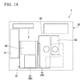
- the specimen-introducing part 40 is moved to the purification treatment unit 50 (S1).
- the dispensing section 52 is moved in the purification treatment unit 50.
- Various reagents which are stored in the reagent wells 121 to 126, are put into or taken from the dispensing chips 201 according to a predetermined procedure by the dispensing section 52 through the supply of air (pressurization) or the suction of air (depressurization); are dispensed; and are mixed. Accordingly, cells in the whole blood sample, which is supplied to the sample well 110, are dissolved, so that a cell solution is obtained.
- the ends of the dispensing chips 201 are inserted into the sealing film 104 that seals the reagent wells 121 to 126.
- Through-holes are formed at the sealing film 104, and various reagents stored in the reagent wells 121 to 126 are sucked by the dispensing chips 201.
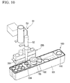
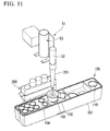
- the extraction filter cartridge 150 is transported to the waste liquid well 130, and a solution in which the cells are dissolved is supplied to the extraction filter cartridge 150 as shown in FIG. 11 .
- the dispensing chip 201 returns to the dispensing chip rack 200 and the pressurizing section 53 then comes into contact with the upper end 151A of the extraction filter cartridge 150.
- the pressurizing section 53 supplies gas into the extraction filter cartridge 150 from the upper end 151A of the extraction filter cartridge 150 so that liquid passes through the adsorption filter 152A. It is possible to increase the speed of liquid, which passes through the adsorption filter 152A, by pressurizing the extraction filter cartridge body 151 by the pressurizing section 53 as described above.
- the solution in which the cells are dissolved passes through the adsorption filter 152A and nucleic acid is adsorbed on the adsorption filter 152A. After that, the adsorption filter 152A is washed with the solution 122A that dissolves biological materials.
- the biological materials are cytoplasm and the like that are not completely dissolved in the solution 121A and cause the carrier to be clogged.
- the washing solutions 123A and 124A are supplied to the adsorption filter 152A and the adsorption filter 152A is washed with the washing solutions 123A and 124A.
- the extraction filter cartridge 150 is transported to the collection well 140 by the robot hand 51, and the eluate 125A is supplied to the adsorption filter 152A by the dispensing section 52 and the dispensing chips 201.
- nucleic acid which has been adsorbed on the adsorption filter 152A, is eluted in the eluate 125A, and a nucleic acid solution containing nucleic acid is collected at the collection well 140.
- the diluted solution 126A is blended with the eluate 125A containing nucleic acid, so that the preparation of a sample is completed.
- the isolation and purification of nucleic acid, which are performed by the nucleic acid purification kit 10, are completed in this way.
- nucleic acid solution containing nucleic acid is transported to the nucleic acid analysis chip 20 from the collection well 140 with the dispensing chip 201 by the dispensing section 52 (S3).
- nucleic acid solution is fed to the main flow passages 24 of the nucleic acid analysis chip 20 from the injection port 26 of the nucleic acid analysis chip 20. At this time, the nucleic acid solution does not flow into the branch flow passages 25 from the main flow passages 24.
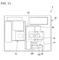
- the specimen-introducing part 40 is moved to the centrifugal liquid feed unit 60 as shown in FIG. 13 (S4).
- the nucleic acid analysis chip 20 is rotated about the central axis O by the centrifugal liquid feed unit 60 and a centrifugal force is applied to the nucleic acid solution stored in the main flow passages 24 of the nucleic acid analysis chip 20, the nucleic acid solution is fed to each of the reaction containers 22 of the nucleic acid analysis chip 20 (S5).
- the specimen-introducing part 40 is moved to the purification treatment unit 50 again while the nucleic acid analysis chip 20 is placed on the specimen-introducing part (see FIG. 9 , S6).
- the oil 127A which is stored in the oil well 127 of the nucleic acid extraction kit 10 shown in FIG. 4 , is sucked into the dispensing chip 201.
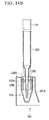
- the oil 127A may adhere to the outer surface of the dispensing chip 201 in the shape of a drop as shown in FIG. 14A .
- the dispensing section 52 moves the dispensing chip 201 to the oil-removing unit 128 as shown in FIG. 14A .
- the dispensing section 52 inserts an end 201 A of the dispensing chip 201 into the slit 129C of the wiping filter 129A of the oil-removing unit 128.
- the oil 127A which adheres to the outer peripheral surface of the end 201A of the dispensing chip 201, is absorbed in the wiping filter 129A and removed from the outer peripheral surface of the dispensing chip 201.
- the dispensing chip 201 is taken out of the slit 129C, the outer peripheral surface of the dispensing chip 201 comes into contact with the wiping filter 129A again. Accordingly, the oil 127A adhering to the outer peripheral surface of the dispensing chip 201 is wiped off.
- the dispensing chip 201 which holds the oil 127A therein and where the oil 127A of the outer peripheral surface has been removed, is transported to the nucleic acid analysis chip 20 by the dispensing section 52. Moreover, the end 201A of the dispensing chip 201 is inserted into the injection port 26 of the nucleic acid analysis chip 20 shown in FIG. 8A and the oil 127A is fed to the main flow passages 24 from the injection port 26 (S7). At this time, the main flow passages 24 are filled with the oil 127A, but the oil 127A does not flow into the branch flow passages 25.
- the specimen-introducing part 40 is moved to the centrifugal liquid feed unit 60 again while the nucleic acid analysis chip 20 is placed on the specimen-introducing part (see FIG. 13 , S8). Moreover, the nucleic acid analysis chip 20 is rotated about the central axis O by the centrifugal liquid feed unit 60.
- a centrifugal force is applied to the oil 127A stored in the main flow passages 24 of the nucleic acid analysis chip 20 shown in FIG. 8A , the oil 127A is substituted with air of the branch flow passages 25 and the respective branch flow passages 25 are filled with the oil 127A (S9).
- the specific gravity of the oil 127A is smaller than that of the nucleic acid solution.
- the nucleic acid solution is positioned at the outer portion of the nucleic acid analysis chip 20 in the radial direction. Accordingly, while the reaction containers 22 are filled with the nucleic acid solution, the oil 127A does not flow into the reaction containers 22.
- the specimen-introducing part 40 is moved to the temperature control mechanism 80 of the analysis unit 70 while the nucleic acid analysis chip 20 is placed on the specimen-introducing part (S10).
- the nucleic acid analysis chip 20 is inserted between the upper and lower heat plates 81 and 82.
- the nucleic acid analysis chip 20 is interposed between the upper and lower heat plates 81 and 82 as shown in FIG. 16 .
- the protruding wall portion 28 comes into contact with the upper heat plate 81 and is elastically deformed, so that the protruding wall portion 28 comes into close contact with the upper heat plate 81. Accordingly, the injection port 26 and the outlet 27 (see FIG. 8A ) are hermetically sealed by the protruding wall portion 28.
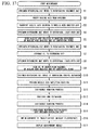
- the upper and lower heat plates 81 and 82 are heated or cooled according to a preset temperature change. Accordingly, the temperature of the nucleic acid solution, which is stored in the reaction containers 22 of the nucleic acid analysis chip 20, is changed according to the preset temperature change. After that, nucleic acid amplifying reactions (PCR reactions) according to the specificities of the primer sets received in the container 22 are performed in each of the reaction containers 22 (S11).
- PCR reactions nucleic acid amplifying reactions
- the reaction containers 22 are heated at a temperature of, for example, 99°C for 10 minutes in order to deactivate DNA polymerase contained in the reaction containers 22 (S 13).
- a temperature of, for example, 99°C for 10 minutes in order to deactivate DNA polymerase contained in the reaction containers 22 (S 13).
- air bubbles are generated from the reagents and the like stored in the reaction containers 22 and may remain in the reaction containers 22.
- an air bubble removing process (S12) for removing air bubbles generated in the reaction containers 22 during the PCR reactions may be performed before DNA polymerase is deactivated (S 13) after the completion of the PCR reactions.
- an air bubble removing process (S 14) may be performed after DNA polymerase is deactivated (S 13). That is, any one of the air bubble removing processes (S 12 and S 14) may be performed one or two times.
- the air bubble removing process is a process that rapidly cools the temperature of the reaction containers 22 of the nucleic acid analysis chip 20 to room temperature by the temperature control mechanism 80, moves the nucleic acid analysis chip 20 to the centrifugal liquid feed unit 60 from the analysis unit 70, and rotates the nucleic acid analysis chip 20 about the central axis O. Accordingly, the air bubbles remaining in the reaction containers 22 are extruded toward the flow passages 23 through centrifugal force that is applied to the liquid contained in the reaction containers 22 and the flow passages 23.
- SNP is measured by the invader (registered trademark) method in the reaction containers 22.
- the analysis unit 70 is moved relative to the specimen-introducing part 40 so that the fluorescence measuring section 90 of the analysis unit 70 overlaps the nucleic acid analysis chip 20 (S 15).
- the temperature of the lower heat plate 82 is controlled so that the temperature of the liquid contained in the reaction container 22 is in the range of 60°C to 70°C, preferably 63°C. Accordingly, an enzyme reaction is performed in the nucleic acid analysis chip 20 by the invader (registered trademark) method.
- excitation light which is generated by the optical part 91, is emitted to the reaction containers 22 through the optical fiber (not shown).
- Two kinds of excitation light having wavelengths of 480 nm and 545 nm are used in this embodiment in order to use measurement using the invader (registered trademark) method.
- a fluorescent material used in the invader (registered trademark) method is, specifically, FAM and RedmondRed. Since the reaction container 22 is transparent and can transmit light having a wavelength of 350 nm to 780 nm, excitation light reaches the inner portion of the reaction container 22 and reaches a fluorescent material released from the signal probe in the reaction container 22. In the reaction container 22, the fluorescence intensity is increased in proportion to the amount of the released fluorescent material.
- the fluorescence measuring section 90 sequentially measures the fluorescence intensity of each of FAM and RedmondRed in the reaction containers 22 in the circumferential direction of the nucleic acid analysis chip 20 (S16). Information measured by the fluorescence measuring section 90 is displayed on the terminal 2 shown in FIG. 1 (S 17), so that a user can know which SNP is contained in nucleic acid.
- the purification of the nucleic acid using the nucleic acid purification kit 10 is performed by the purification treatment unit 50. Further, after a nucleic acid solution is fed to the respective reaction container 22 of the nucleic acid analysis chip 20 by the centrifugal liquid feed unit 60, the analysis of nucleic acid is performed by the analysis unit 70. As described above, the analysis of nucleic acid is performed while the respective units interlock with each other and the processes from the purification of nucleic acid to the analysis of nucleic acid can be automatically performed by the analyzer body 30. Accordingly, it is possible to easily perform an accurate gene test.
- a process where a user's manual work is performed is a process that supplies a specimen (whole blood sample) to the sample well 11 of the nucleic acid purification kit 10 and places the nucleic acid purification kit 10 on the tray 41.
- This process does not require an accurate liquid operation, and all accurate liquid operations are performed by the analyzer body 30. Accordingly, even if a user is not skilled at liquid operations, the user can perform a gene test having high reproducibility.
- the analysis unit 70 includes the temperature control mechanism 80, it is possible to immediately perform PCR reactions in the reaction containers 22 of the nucleic acid analysis chip 20 after the nucleic acid solution and the oil 127A are supplied to the nucleic acid analysis chip 20. For this reason, since a user's manual work is not needed, an operation is simple and it is possible to perform a gene test with accuracy through the increase of the specificities of PCR reactions.
- the analysis unit 70 includes the fluorescence measuring section 90, it is possible to measure the fluorescence of the fluorescent materials that are excited in the reaction containers 22 by excitation light.
- the nucleic acid purification kit 10 includes the oil-removing unit 128, it is possible to remove the oil 127A, which adheres to the outer peripheral surface of the end 201A of the dispensing chip 201, by the wiping filter 129A of the oil-removing unit 128. Accordingly, when the end 201A of the dispensing chip 201 is inserted into the injection port 26 of the nucleic acid analysis chip 20, it is possible to suppress the adhering of the oil 127A to the outer surface of the nucleic acid analysis chip 20 around the injection port 26. As a result, when the nucleic acid analysis chip 20 is rotated by the centrifugal liquid feed unit 60, it is possible to suppress the scattering of the oil 127A that is caused through centrifugal force.
- reagents and a filter unit which are necessary to extract nucleic acid, are provided in the reagent cartridge 100 and integrated as a set, only an operation for adding a specimen to the sample well 110 and placing the reagent cartridge on the tray 41 of the specimen-introducing part 40 needs to be manually performed. Accordingly, it is possible to easily perform a gene test. Furthermore, since the waste liquid well 130 is integrally formed at the reagent cartridge 100, the reagent cartridge 100 merely needs to be removed and discarded from the tray 41 after the completion of a gene test. For this reason, since the treatment of waste liquid is simple, there is no concern that surroundings are contaminated with liquid remaining on a specimen and the like.
- the reagent well portion 120 is sealed by the sealing film 104 provided on the reagent cartridge 100 and the reagents and the like can be sucked through the sealing film 104 by the end 201 A of the dispensing chip 201, the reagent well portion 120 can be hermetically sealed until just before the reagents and the like are needed.
- a holding portion 160 which holds the extraction filter cartridge 150, is formed at the reagent cartridge 100. Accordingly, the extraction filter cartridge 150 does not fall down in the reagent cartridge 100 or the displacement of the extraction filter cartridge 150 does not occur in the reagent cartridge 100. Therefore, it is possible to automate the purification of nucleic acid through the stabilization of the posture of the extraction filter cartridge 150.
- the sealing film 103 which seals the opening of the reagent cartridge 100, is provided, it is possible to suppress the mixing of foreign materials to the extraction filter cartridge 150, the sample well 110, the collection well 140, and the like.
- the claw portions 102 which fix the reagent cartridge to the tray 41, are formed at the reagent cartridge 100, the reagent cartridge 100 does not fall down or the reagent cartridge 100 is not displaced even though the specimen-introducing part 40 is moved in the analyzer body 30.
- the flow passages 23 of the nucleic acid analysis chip 20 are formed closer to the central axis O than the reaction containers 22, it is possible to feed liquid to each of the reaction containers 22 from the flow passages 23 by rotating the nucleic acid analysis chip 20 about the central axis O.
- the injection port 26 is positioned on the central axis O, a centrifugal force applied to liquid, such as reagents or oil, adhering to the outer surface around the injection port 26 is small. Accordingly, when the nucleic acid analysis chip 20 is rotated about the central axis O by the centrifugal liquid feed unit 60, the scattering of the liquid, such as reagents or oil, is suppressed.
- the protruding wall portion 28, which protrudes from the outer surface of the nucleic acid analysis chip body 21, is formed so as to surround the injection port 26, it is possible to hermetically seal the peripheral portion of the injection port 26 by making the protruding wall portion 28 come into contact with the upper heat plate 81 or the like. Accordingly, it is possible to prevent liquid and the like from being blown out of the injection port 26. Further, since the protruding wall portion 28 has elasticity, it is possible to make the protruding wall portion 28 and the upper heat plate 81 come into close contact with each other.
- the flow restricting portions 25A are provided between the main flow passages 24 and the branch flow passages 25, it is possible to feed liquid to the reaction containers 22 through the branch flow passages 25 after all of the main flow passages 24 are filled with liquid.
- chevron shapes 24C are formed at the main flow passages 24, the main flow passages 24 divided by the chevron shapes 24C can store the same amount of liquid. For this reason, it is possible to make the amount of liquid, which is fed to each of the reaction containers 22, uniform and to reduce an error of a biochemical reaction of each of the reaction containers 22.
- reaction container 22 has optical transparency, it is possible to perform optical measurement of the inside of the reaction container 22 from the outside of the nucleic acid analysis chip 20.
- the nucleic acid analysis chip 20 includes the chip body 21 where the reaction containers 22 and the flow passages 23 are formed and the lid body 29 that is attached to the chip body 21, it is easy to dispose different probes, primers, and reagents in each of the reaction containers 22. Moreover, after the lid body 29 is attached to the chip body 21, biochemical reaction can be preferably performed in each of the reaction containers 22 as independent reaction spaces.
- the lid body 29 is made of a metal material, it is possible to rapidly heat and cool each of the reaction containers 22.
- Examples of gene analysis, which uses the nucleic acid analyzer 1 according to this embodiment, may include the detection of K-ras germline mutation and the detection of germline mutation.
- a K-ras gene is known as a cancer gene derived from a virus, and is a gene that codes a type of G protein having GTPase activity. It is considered that when a point mutation occurs at the K-ras gene, GTPase activity is reduced, so that the change of a cell to a cancer is caused.
- Germline mutation is an individual characteristic mutation that occurs while a reproductive cell has mutation, and there is the same mutation in all individual cells. It is considered that it is possible to estimate differences and the like of, for example, drug susceptibility by analyzing germline mutation.
- the nucleic acid analyzer 1 is used to detect a K-ras germline mutation.
- Probes which correspond to a wild type of the K-ras gene and thirteen mutation types, and salt and the above-mentioned enzyme used to amplify nucleic acid are previously stored in each of the reaction containers 22. In this case, since fourteen types of probes are provided, fourteen reaction containers 22 are used at the nucleic acid analysis chip 20.
- a user supplies a specimen, which is suspected as pancreatic cancer, bowel cancer, or the like, to the sample well 110 of the reagent cartridge 100 of the nucleic acid purification kit 10, and performs the extraction of nucleic acid, the amplifying reaction of a gene in nucleic acid, and the measurement of fluorescence intensity by operating the nucleic acid analyzer 1 as described above. Accordingly, it is possible to determine whether the specimen has a K-ras germline mutation or not and which mutation type among K-ras mutation types corresponds to the K-ras germline mutation.
- germline mutation is a mutation common to all individual cells, it is possible to detect a germline mutation by using, for example, a whole blood sample or the like. Specifically, it is possible to detect a germline mutation by specifying the SNP of the specimen.
- a PCR-PHFA PCR-Preferential Homoduplex Formation Assay
- invader registered trademark
- Taqman PCR method a method of specifying SNP
- nucleic acid analyzer 1 may also be preferably used in these methods.
- the analysis unit 70 includes the temperature control mechanism 80 and the fluorescence measuring section 90, but it is possible to more easily perform an accurate gene test even if the analysis unit 70 does not include the temperature control mechanism 80 and the fluorescence measuring section 90.
- the nucleic acid purification kit 10 include a dispensing chip rack 200 in which oil 127A and at least an oil-dispensing chip 201 dispensing oil are stored and an oil-removing unit 128 removing surplus oil adhering to the outer surface of the end portion of the oil-dispensing chip 201. Furthermore, it is preferable that the nucleic acid purification kit 10 include a box-shaped reagent cartridge 100 and a reagent-dispensing chip 201 and the reagent cartridge 100 include a sample well 110, an oil well 127, reagent wells 121, 122, 123, 124, 125, and 126, a waste liquid well 130, and an extraction filter cartridge 150.
- the reagent cartridge 100 is provided with a sealing film (opening portion sealing film) 104 that is formed so as to be capable of being penetrated by the end of the reagent-dispensing chip 201 or the oil-dispensing chip 201, but is not limited thereto.
- the holding portion 160 in which the extraction filter cartridge 150 is received is formed integrally with the reagent cartridge 100, but is not limited thereto.
- the claw portions 102 have been formed as the positioning mechanism that positions the reagent cartridge 100 on the specimen-introducing part 40, but is not limited thereto.
- the nucleic acid analysis chip 20 has included the flow passages 23 and the injection port 26, but is not limited thereto.
- the nucleic acid analysis chip 20 has included the chip body 21 and the lid body 29, but is not limited thereto. It is preferable that at least one of the chip body 21 and the lid body 29 have optical transparency.
- the protruding wall portion 28, which protrudes from the outer surface of the chip body 21 so as to surround the injection port 26 and the outlet 27, has been described, but is not limited thereto. Further, the protruding wall portion 28 has elasticity, but is not limited thereto.
- the flow passage 23 includes the main flow passage 24 and the branch flow passage 25, but is not limited thereto.
- the main flow passage 24 has a chevron shape, but is not limited thereto.
Landscapes
- Health & Medical Sciences (AREA)
- Chemical & Material Sciences (AREA)
- General Health & Medical Sciences (AREA)
- Analytical Chemistry (AREA)
- General Physics & Mathematics (AREA)
- Life Sciences & Earth Sciences (AREA)
- Biochemistry (AREA)
- Physics & Mathematics (AREA)
- Immunology (AREA)
- Pathology (AREA)
- Nuclear Medicine, Radiotherapy & Molecular Imaging (AREA)
- Hematology (AREA)
- Clinical Laboratory Science (AREA)
- Chemical Kinetics & Catalysis (AREA)
- Apparatus Associated With Microorganisms And Enzymes (AREA)
- Measuring Or Testing Involving Enzymes Or Micro-Organisms (AREA)
- Investigating, Analyzing Materials By Fluorescence Or Luminescence (AREA)
- Investigating Or Analysing Biological Materials (AREA)
- Automatic Analysis And Handling Materials Therefor (AREA)
Applications Claiming Priority (2)
| Application Number | Priority Date | Filing Date | Title |
|---|---|---|---|
| JP2009228809 | 2009-09-30 | ||
| PCT/JP2010/067030 WO2011040504A1 (ja) | 2009-09-30 | 2010-09-30 | 核酸分析装置 |
Publications (3)
| Publication Number | Publication Date |
|---|---|
| EP2484748A1 true EP2484748A1 (de) | 2012-08-08 |
| EP2484748A4 EP2484748A4 (de) | 2016-05-11 |
| EP2484748B1 EP2484748B1 (de) | 2017-02-22 |
Family
ID=43826316
Family Applications (1)
| Application Number | Title | Priority Date | Filing Date |
|---|---|---|---|
| EP10820619.4A Not-in-force EP2484748B1 (de) | 2009-09-30 | 2010-09-30 | Nukleinsäureanalysegerät |
Country Status (6)
| Country | Link |
|---|---|
| US (1) | US9267890B2 (de) |
| EP (1) | EP2484748B1 (de) |
| JP (2) | JP5003845B2 (de) |
| CN (1) | CN102549140B (de) |
| TW (1) | TWI523950B (de) |
| WO (1) | WO2011040504A1 (de) |
Cited By (3)
| Publication number | Priority date | Publication date | Assignee | Title |
|---|---|---|---|---|
| EP2784513A4 (de) * | 2011-11-25 | 2015-07-15 | Toppan Printing Co Ltd | Probenanalysechip, probenanalyseverfahren und genanalyseverfahren |
| EP3113886A4 (de) * | 2014-03-07 | 2017-10-25 | CapitalBio Corporation | Mikrofluidischer multiindex-detektionschip und verfahren zur verwendung |
| US11883825B2 (en) | 2017-11-02 | 2024-01-30 | Memed Diagnostics Ltd. | Cartridge and system for analyzing body liquid |
Families Citing this family (48)
| Publication number | Priority date | Publication date | Assignee | Title |
|---|---|---|---|---|
| US9267894B2 (en) | 2012-08-10 | 2016-02-23 | Hamamatsu Photonics K.K. | Method for making surface enhanced Raman scattering device |
| JP5867668B2 (ja) | 2010-12-01 | 2016-02-24 | セイコーエプソン株式会社 | 熱サイクル装置及び熱サイクル方法 |
| JP5896100B2 (ja) * | 2011-03-01 | 2016-03-30 | セイコーエプソン株式会社 | 熱サイクル装置 |
| JP2013108774A (ja) * | 2011-11-17 | 2013-06-06 | Toppan Printing Co Ltd | 圧力検査装置 |
| CN103975244A (zh) | 2011-11-25 | 2014-08-06 | 凸版印刷株式会社 | 分注装置使用的移液管吸头组件及使用其对卡盒薄膜开孔的开孔方法 |
| US10551322B2 (en) | 2012-08-10 | 2020-02-04 | Hamamatsu Photonics K.K. | Surface-enhanced Raman scattering unit including integrally formed handling board |
| JP5921380B2 (ja) | 2012-08-10 | 2016-05-24 | 浜松ホトニクス株式会社 | 表面増強ラマン散乱ユニット |
| EP2884264B1 (de) | 2012-08-10 | 2019-11-20 | Hamamatsu Photonics K.K. | Oberflächenverstärktes raman-streuungselement und herstellungsverfahren dafür |
| JP6058313B2 (ja) | 2012-08-10 | 2017-01-11 | 浜松ホトニクス株式会社 | 表面増強ラマン散乱ユニット |
| EP2889606A4 (de) * | 2012-08-10 | 2016-04-20 | Hamamatsu Photonics Kk | Oberflächenverstärkte ramanstreuungseinheit und verwendungsverfahren dafür |
| CN104508466B (zh) | 2012-08-10 | 2018-07-17 | 浜松光子学株式会社 | 表面增强拉曼散射元件 |
| CN104541158B (zh) | 2012-08-10 | 2017-05-24 | 浜松光子学株式会社 | 表面增强拉曼散射元件、以及制造表面增强拉曼散射元件的方法 |
| JP5945192B2 (ja) | 2012-08-10 | 2016-07-05 | 浜松ホトニクス株式会社 | 表面増強ラマン散乱ユニット |
| JP6055234B2 (ja) | 2012-08-10 | 2016-12-27 | 浜松ホトニクス株式会社 | 表面増強ラマン散乱ユニット |
| JP6023509B2 (ja) | 2012-08-10 | 2016-11-09 | 浜松ホトニクス株式会社 | 表面増強ラマン散乱ユニット |
| JP5921381B2 (ja) | 2012-08-10 | 2016-05-24 | 浜松ホトニクス株式会社 | 表面増強ラマン散乱ユニット |
| JP5908370B2 (ja) | 2012-08-10 | 2016-04-26 | 浜松ホトニクス株式会社 | 表面増強ラマン散乱ユニット |
| JP6155589B2 (ja) * | 2012-09-27 | 2017-07-05 | 凸版印刷株式会社 | 生化学物質を処理または分析するための生化学反応チップ及びその分析方法 |
| JP6155591B2 (ja) * | 2012-09-28 | 2017-07-05 | 凸版印刷株式会社 | 複数試料を分析するための試料分析チップとその分析方法 |
| KR101415001B1 (ko) | 2012-10-30 | 2014-07-04 | 한국해양과학기술원 | 핵산 추출 또는 증폭을 위한 휴대용 장치 |
| EP2972219B1 (de) | 2013-03-15 | 2022-01-19 | Abbott Laboratories | Automatisierter reagensmanager eines diagnostischen analysatorsystems |
| GB2520063B (en) * | 2013-11-08 | 2018-01-31 | Intelligent Fingerprinting Ltd | Skin-print fluorescence analysis method and apparatus |
| EP3070156B1 (de) * | 2013-11-12 | 2018-12-26 | Boditech Med Inc. | Küvette mit mehreren vertiefungen sowie mit integrierter reaktions- und detektionsfunktion |
| JP6334251B2 (ja) * | 2014-05-09 | 2018-05-30 | 東洋鋼鈑株式会社 | 遺伝子検査装置 |
| CN105940094B (zh) | 2014-06-17 | 2018-02-23 | 深圳迈瑞生物医疗电子股份有限公司 | 核酸提取装置及其工作方法 |
| JP6410194B2 (ja) * | 2014-07-24 | 2018-10-24 | 国立大学法人九州大学 | 温度制御モジュールおよび光測定装置 |
| KR102186835B1 (ko) * | 2014-11-03 | 2020-12-04 | 주식회사 람다트 | 체외진단용 분석장치의 카트리지 |
| JP6812797B2 (ja) * | 2014-11-04 | 2021-01-13 | 凸版印刷株式会社 | 核酸導入方法、核酸検出方法、生体成分解析方法、生体成分定量用アレイデバイス、及び生体成分解析キット |
| WO2016203856A1 (ja) * | 2015-06-17 | 2016-12-22 | 株式会社 日立ハイテクノロジーズ | 自動分析装置 |
| JP6672790B2 (ja) * | 2015-12-28 | 2020-03-25 | 凸版印刷株式会社 | 試薬カートリッジ及び核酸精製キット |
| US11958052B2 (en) | 2016-04-07 | 2024-04-16 | Metaboscreen Co., Ltd. | Thermocycling inspection device and chip holder |
| CN108884430B (zh) * | 2016-04-20 | 2019-11-19 | 希森美康株式会社 | 核酸分析装置及核酸分析方法 |
| CN109072155A (zh) * | 2016-04-20 | 2018-12-21 | 希森美康株式会社 | 核酸分析装置及核酸分析方法 |
| JP6831539B2 (ja) * | 2017-05-22 | 2021-02-17 | 栄研化学株式会社 | 試薬カートリッジ |
| US10117615B1 (en) * | 2017-08-01 | 2018-11-06 | Nova Biomedical Corporation | Analyzer cartridge with capillary wiper |
| CN107356587B (zh) * | 2017-08-24 | 2024-03-01 | 北京贝泰科技有限公司 | 一种光激化学发光即时检测系统 |
| CN111372650A (zh) * | 2017-09-30 | 2020-07-03 | 因思科瑞普特公司 | 流通式电穿孔仪器 |
| WO2019097984A1 (ja) * | 2017-11-15 | 2019-05-23 | コニカミノルタ株式会社 | 検査パッケージ |
| CN111902722A (zh) * | 2018-03-19 | 2020-11-06 | 凸版印刷株式会社 | 收容容器、试剂容器用盖材料、试剂容器及试剂盒 |
| JP2019174188A (ja) * | 2018-03-27 | 2019-10-10 | 凸版印刷株式会社 | 試薬カートリッジ、核酸抽出セットおよび溶液廃棄方法 |
| CN108918467B (zh) * | 2018-05-14 | 2021-05-18 | 中国科学院苏州生物医学工程技术研究所 | 一种高通量干式化学检测装置 |
| CN108414737A (zh) * | 2018-06-13 | 2018-08-17 | 安徽为臻生物工程技术有限公司 | 一种全自动化学发光免疫分析仪 |
| CN110501488A (zh) * | 2019-08-19 | 2019-11-26 | 昆山汇先医药技术有限公司 | 一种微流控样品处理设备的托盘装置 |
| CN113234589B (zh) * | 2021-05-10 | 2024-03-26 | 宁波康程德诺生物医药有限公司 | 一种核酸快速提取四联管装置、试剂盒和提取方法 |
| CN113546701B (zh) * | 2021-07-26 | 2022-06-24 | 绿叶诊断产品技术(广东)有限公司 | 一种检测装置及检测方法 |
| CN113877639A (zh) * | 2021-11-18 | 2022-01-04 | 天长市万宏实验仪器设备有限公司 | 一种具备空气过滤装置的化学试剂柜 |
| USD970036S1 (en) | 2022-05-05 | 2022-11-15 | Singular Genomics Systems, Inc. | Reagent cartridge |
| USD979093S1 (en) | 2022-05-05 | 2023-02-21 | Singular Genomics Systems, Inc. | Reagent cartridge |
Family Cites Families (26)
| Publication number | Priority date | Publication date | Assignee | Title |
|---|---|---|---|---|
| JPH0623767B2 (ja) | 1989-03-07 | 1994-03-30 | 出光石油化学株式会社 | 液体試料の分析方法およびその装置 |
| AU722335B2 (en) | 1995-07-31 | 2000-07-27 | Precision System Science Co., Ltd. | Container |
| US6734401B2 (en) * | 2000-06-28 | 2004-05-11 | 3M Innovative Properties Company | Enhanced sample processing devices, systems and methods |
| CA2423552A1 (en) * | 2000-10-13 | 2002-04-18 | Irm Llc | High throughput processing system and method of using |
| KR100710122B1 (ko) * | 2001-05-09 | 2007-04-20 | 엑시스-시일드 에이에스에이 | 분석 시스템 |
| WO2003057369A1 (en) * | 2001-12-21 | 2003-07-17 | 3M Innovative Properties Company | Centrifugal filling of sample processing devices |
| JP2003310260A (ja) * | 2002-04-30 | 2003-11-05 | Olympus Optical Co Ltd | 遺伝子検査システムおよび遺伝子検査方法 |
| JP2004309145A (ja) * | 2003-04-02 | 2004-11-04 | Hitachi High-Technologies Corp | 化学分析装置及び化学分析用構造体 |
| JP2005062084A (ja) | 2003-08-19 | 2005-03-10 | Fuji Photo Film Co Ltd | 核酸抽出装置用ラック |
| JP2005192558A (ja) | 2003-10-20 | 2005-07-21 | Fuji Photo Film Co Ltd | 核酸分離精製用の核酸吸着性多孔性膜及び核酸分離精製装置 |
| JP2005204579A (ja) | 2004-01-23 | 2005-08-04 | Fuji Photo Film Co Ltd | 抽出装置 |
| JP2005257337A (ja) | 2004-03-09 | 2005-09-22 | Brother Ind Ltd | 検査対象受体、検査装置、及び検査方法 |
| CN1965080A (zh) * | 2004-06-02 | 2007-05-16 | 爱科来株式会社 | 核酸提取用容器、固体基件的洗净方法及洗净机构、和核酸精制方法 |
| EP1767623A4 (de) * | 2004-06-02 | 2008-09-17 | Arkray Inc | Behälter zu nukleinsäureextraktion, verfahren zur reinigung einer festen matrix und entsprechender reinigungsmechanismus sowie verfahren zur aufreinigung von nukleinsäure |
| EP1757679A1 (de) * | 2004-06-02 | 2007-02-28 | ARKRAY, Inc. | Behälter für nukleinsäureamplifikation, nukleinsäurepräparationskit und nukleinsäureanalysegerät |
| JP3699721B1 (ja) * | 2004-10-28 | 2005-09-28 | 株式会社石川製作所 | 検体試料の遠心分注方法及び遠心分注装置 |
| JP4742050B2 (ja) | 2004-11-19 | 2011-08-10 | 株式会社島津製作所 | 検査試薬キットとそれを用いる遺伝子多型検出装置 |
| JP2007330845A (ja) | 2006-06-12 | 2007-12-27 | Fujifilm Corp | 特定物質抽出装置 |
| JP2008083017A (ja) * | 2006-09-26 | 2008-04-10 | Taiyo Yuden Co Ltd | 液体試料の流路を有する分析用媒体及び液体試料を流動させる方法 |
| WO2008123019A1 (ja) * | 2007-03-05 | 2008-10-16 | Olympus Corporation | 遺伝子変化の検出方法および検出装置 |
| US8828712B2 (en) | 2007-06-29 | 2014-09-09 | Toppan Printing Co., Ltd. | Genetic detection and determination apparatus and method, gene reactor, and incubator |
| US8133671B2 (en) * | 2007-07-13 | 2012-03-13 | Handylab, Inc. | Integrated apparatus for performing nucleic acid extraction and diagnostic testing on multiple biological samples |
| JP5011012B2 (ja) | 2007-07-18 | 2012-08-29 | 株式会社日立ハイテクノロジーズ | 核酸抽出装置 |
| JP2009041984A (ja) * | 2007-08-07 | 2009-02-26 | Arkray Inc | 分析装置、分析用具、および光学検知システム |
| JP2009097936A (ja) | 2007-10-16 | 2009-05-07 | Panasonic Corp | 生体サンプル判別用プレート及びそれを用いた溶液充填方法 |
| JP2009228809A (ja) | 2008-03-24 | 2009-10-08 | Ntn Corp | 等速自在継手 |
-
2010
- 2010-09-29 TW TW099133014A patent/TWI523950B/zh not_active IP Right Cessation
- 2010-09-30 JP JP2011527917A patent/JP5003845B2/ja active Active
- 2010-09-30 CN CN201080043522.XA patent/CN102549140B/zh not_active Expired - Fee Related
- 2010-09-30 US US13/498,818 patent/US9267890B2/en not_active Expired - Fee Related
- 2010-09-30 WO PCT/JP2010/067030 patent/WO2011040504A1/ja active Application Filing
- 2010-09-30 EP EP10820619.4A patent/EP2484748B1/de not_active Not-in-force
-
2012
- 2012-05-24 JP JP2012118973A patent/JP2012161340A/ja active Pending
Non-Patent Citations (1)
| Title |
|---|
| See references of WO2011040504A1 * |
Cited By (4)
| Publication number | Priority date | Publication date | Assignee | Title |
|---|---|---|---|---|
| EP2784513A4 (de) * | 2011-11-25 | 2015-07-15 | Toppan Printing Co Ltd | Probenanalysechip, probenanalyseverfahren und genanalyseverfahren |
| EP3113886A4 (de) * | 2014-03-07 | 2017-10-25 | CapitalBio Corporation | Mikrofluidischer multiindex-detektionschip und verfahren zur verwendung |
| US10300483B2 (en) | 2014-03-07 | 2019-05-28 | Capitalbio Technology Corporation | Multi-index detection microfluidic chip and methods of use |
| US11883825B2 (en) | 2017-11-02 | 2024-01-30 | Memed Diagnostics Ltd. | Cartridge and system for analyzing body liquid |
Also Published As
| Publication number | Publication date |
|---|---|
| US20120184025A1 (en) | 2012-07-19 |
| JP5003845B2 (ja) | 2012-08-15 |
| JPWO2011040504A1 (ja) | 2013-02-28 |
| TW201116631A (en) | 2011-05-16 |
| CN102549140B (zh) | 2014-04-02 |
| CN102549140A (zh) | 2012-07-04 |
| TWI523950B (zh) | 2016-03-01 |
| EP2484748B1 (de) | 2017-02-22 |
| WO2011040504A1 (ja) | 2011-04-07 |
| JP2012161340A (ja) | 2012-08-30 |
| EP2484748A4 (de) | 2016-05-11 |
| US9267890B2 (en) | 2016-02-23 |
Similar Documents
| Publication | Publication Date | Title |
|---|---|---|
| EP2484748B1 (de) | Nukleinsäureanalysegerät | |
| JP6838127B2 (ja) | 統合された移送モジュールを有する試験カートリッジ | |
| KR101917402B1 (ko) | 자동 반응ㆍ광측정 장치 및 그 방법 | |
| JP4820756B2 (ja) | 反応容器、反応容器液導入装置、液導入反応測定装置、および液導入装置 | |
| JP4755588B2 (ja) | 反応容器、反応測定装置、および液回転処理装置 | |
| KR101339544B1 (ko) | 생체물질 고정담체 봉입 칩, 생체물질 고정담체 처리장치및 그 처리방법 | |
| US8642293B2 (en) | Disposable device for analyzing a liquid sample containing a nucleic acid with a nucleic acid amplification apparatus | |
| JP6449017B2 (ja) | 直動型反応処理装置およびその方法 | |
| TWI628283B (zh) | 反應容器用光測定裝置及該方法 | |
| KR101900120B1 (ko) | 반응 용기 및 그 제조 방법 | |
| JP5991967B2 (ja) | 反応容器用光測定装置およびその方法 | |
| JPWO2006038643A1 (ja) | 反応容器、および反応制御装置 | |
| JP6039395B2 (ja) | コンタミネーションの防止方法 | |
| EP2306204A1 (de) | Nukleinsäure-analysegerät, analyseautomat und analyseverfahren | |
| JP2017018053A (ja) | 核酸抽出キット、核酸抽出方法および核酸抽出装置 | |
| JP6672790B2 (ja) | 試薬カートリッジ及び核酸精製キット | |
| JPH06225752A (ja) | Dnaプローブ自動測定装置およびサンプル中の核酸を測定する方法 |
Legal Events
| Date | Code | Title | Description |
|---|---|---|---|
| PUAI | Public reference made under article 153(3) epc to a published international application that has entered the european phase |
Free format text: ORIGINAL CODE: 0009012 |
|
| 17P | Request for examination filed |
Effective date: 20120403 |
|
| AK | Designated contracting states |
Kind code of ref document: A1 Designated state(s): AL AT BE BG CH CY CZ DE DK EE ES FI FR GB GR HR HU IE IS IT LI LT LU LV MC MK MT NL NO PL PT RO SE SI SK SM TR |
|
| DAX | Request for extension of the european patent (deleted) | ||
| RA4 | Supplementary search report drawn up and despatched (corrected) |
Effective date: 20160407 |
|
| RIC1 | Information provided on ipc code assigned before grant |
Ipc: C12N 15/10 20060101ALI20160401BHEP Ipc: G01N 35/04 20060101ALI20160401BHEP Ipc: G01N 21/03 20060101ALN20160401BHEP Ipc: G01N 35/10 20060101ALN20160401BHEP Ipc: G01N 35/00 20060101ALN20160401BHEP Ipc: G01N 21/07 20060101AFI20160401BHEP Ipc: G01N 21/64 20060101ALI20160401BHEP |
|
| REG | Reference to a national code |
Ref country code: DE Ref legal event code: R079 Ref document number: 602010040256 Country of ref document: DE Free format text: PREVIOUS MAIN CLASS: C12M0001000000 Ipc: G01N0021070000 |
|
| GRAP | Despatch of communication of intention to grant a patent |
Free format text: ORIGINAL CODE: EPIDOSNIGR1 |
|
| RIC1 | Information provided on ipc code assigned before grant |
Ipc: G01N 21/07 20060101AFI20160706BHEP Ipc: B01L 3/00 20060101ALI20160706BHEP Ipc: G01N 21/03 20060101ALN20160706BHEP Ipc: C12N 15/10 20060101ALI20160706BHEP Ipc: G01N 35/10 20060101ALN20160706BHEP Ipc: G01N 35/00 20060101ALN20160706BHEP Ipc: G01N 35/04 20060101ALI20160706BHEP Ipc: G01N 21/64 20060101ALI20160706BHEP |
|
| INTG | Intention to grant announced |
Effective date: 20160804 |
|
| GRAS | Grant fee paid |
Free format text: ORIGINAL CODE: EPIDOSNIGR3 |
|
| RIN1 | Information on inventor provided before grant (corrected) |
Inventor name: AKASHI SHUICHI Inventor name: KAWATA EIJI Inventor name: KUROKI HIROYUKI |
|
| GRAA | (expected) grant |
Free format text: ORIGINAL CODE: 0009210 |
|
| RAP1 | Party data changed (applicant data changed or rights of an application transferred) |
Owner name: TOPPAN PRINTING CO., LTD. |
|
| AK | Designated contracting states |
Kind code of ref document: B1 Designated state(s): AL AT BE BG CH CY CZ DE DK EE ES FI FR GB GR HR HU IE IS IT LI LT LU LV MC MK MT NL NO PL PT RO SE SI SK SM TR |
|
| REG | Reference to a national code |
Ref country code: GB Ref legal event code: FG4D |
|
| REG | Reference to a national code |
Ref country code: CH Ref legal event code: EP |
|
| REG | Reference to a national code |
Ref country code: AT Ref legal event code: REF Ref document number: 869630 Country of ref document: AT Kind code of ref document: T Effective date: 20170315 |
|
| REG | Reference to a national code |
Ref country code: IE Ref legal event code: FG4D |
|
| REG | Reference to a national code |
Ref country code: DE Ref legal event code: R096 Ref document number: 602010040256 Country of ref document: DE |
|
| REG | Reference to a national code |
Ref country code: LT Ref legal event code: MG4D |
|
| REG | Reference to a national code |
Ref country code: NL Ref legal event code: MP Effective date: 20170222 |
|
| REG | Reference to a national code |
Ref country code: AT Ref legal event code: MK05 Ref document number: 869630 Country of ref document: AT Kind code of ref document: T Effective date: 20170222 |
|
| PG25 | Lapsed in a contracting state [announced via postgrant information from national office to epo] |
Ref country code: LT Free format text: LAPSE BECAUSE OF FAILURE TO SUBMIT A TRANSLATION OF THE DESCRIPTION OR TO PAY THE FEE WITHIN THE PRESCRIBED TIME-LIMIT Effective date: 20170222 Ref country code: GR Free format text: LAPSE BECAUSE OF FAILURE TO SUBMIT A TRANSLATION OF THE DESCRIPTION OR TO PAY THE FEE WITHIN THE PRESCRIBED TIME-LIMIT Effective date: 20170523 Ref country code: FI Free format text: LAPSE BECAUSE OF FAILURE TO SUBMIT A TRANSLATION OF THE DESCRIPTION OR TO PAY THE FEE WITHIN THE PRESCRIBED TIME-LIMIT Effective date: 20170222 Ref country code: HR Free format text: LAPSE BECAUSE OF FAILURE TO SUBMIT A TRANSLATION OF THE DESCRIPTION OR TO PAY THE FEE WITHIN THE PRESCRIBED TIME-LIMIT Effective date: 20170222 Ref country code: NO Free format text: LAPSE BECAUSE OF FAILURE TO SUBMIT A TRANSLATION OF THE DESCRIPTION OR TO PAY THE FEE WITHIN THE PRESCRIBED TIME-LIMIT Effective date: 20170522 |
|
| PG25 | Lapsed in a contracting state [announced via postgrant information from national office to epo] |
Ref country code: NL Free format text: LAPSE BECAUSE OF FAILURE TO SUBMIT A TRANSLATION OF THE DESCRIPTION OR TO PAY THE FEE WITHIN THE PRESCRIBED TIME-LIMIT Effective date: 20170222 Ref country code: AT Free format text: LAPSE BECAUSE OF FAILURE TO SUBMIT A TRANSLATION OF THE DESCRIPTION OR TO PAY THE FEE WITHIN THE PRESCRIBED TIME-LIMIT Effective date: 20170222 Ref country code: PT Free format text: LAPSE BECAUSE OF FAILURE TO SUBMIT A TRANSLATION OF THE DESCRIPTION OR TO PAY THE FEE WITHIN THE PRESCRIBED TIME-LIMIT Effective date: 20170622 Ref country code: LV Free format text: LAPSE BECAUSE OF FAILURE TO SUBMIT A TRANSLATION OF THE DESCRIPTION OR TO PAY THE FEE WITHIN THE PRESCRIBED TIME-LIMIT Effective date: 20170222 Ref country code: BG Free format text: LAPSE BECAUSE OF FAILURE TO SUBMIT A TRANSLATION OF THE DESCRIPTION OR TO PAY THE FEE WITHIN THE PRESCRIBED TIME-LIMIT Effective date: 20170522 Ref country code: SE Free format text: LAPSE BECAUSE OF FAILURE TO SUBMIT A TRANSLATION OF THE DESCRIPTION OR TO PAY THE FEE WITHIN THE PRESCRIBED TIME-LIMIT Effective date: 20170222 Ref country code: ES Free format text: LAPSE BECAUSE OF FAILURE TO SUBMIT A TRANSLATION OF THE DESCRIPTION OR TO PAY THE FEE WITHIN THE PRESCRIBED TIME-LIMIT Effective date: 20170222 |
|
| PG25 | Lapsed in a contracting state [announced via postgrant information from national office to epo] |
Ref country code: IT Free format text: LAPSE BECAUSE OF FAILURE TO SUBMIT A TRANSLATION OF THE DESCRIPTION OR TO PAY THE FEE WITHIN THE PRESCRIBED TIME-LIMIT Effective date: 20170222 Ref country code: EE Free format text: LAPSE BECAUSE OF FAILURE TO SUBMIT A TRANSLATION OF THE DESCRIPTION OR TO PAY THE FEE WITHIN THE PRESCRIBED TIME-LIMIT Effective date: 20170222 Ref country code: RO Free format text: LAPSE BECAUSE OF FAILURE TO SUBMIT A TRANSLATION OF THE DESCRIPTION OR TO PAY THE FEE WITHIN THE PRESCRIBED TIME-LIMIT Effective date: 20170222 Ref country code: CZ Free format text: LAPSE BECAUSE OF FAILURE TO SUBMIT A TRANSLATION OF THE DESCRIPTION OR TO PAY THE FEE WITHIN THE PRESCRIBED TIME-LIMIT Effective date: 20170222 Ref country code: SK Free format text: LAPSE BECAUSE OF FAILURE TO SUBMIT A TRANSLATION OF THE DESCRIPTION OR TO PAY THE FEE WITHIN THE PRESCRIBED TIME-LIMIT Effective date: 20170222 |
|
| REG | Reference to a national code |
Ref country code: DE Ref legal event code: R097 Ref document number: 602010040256 Country of ref document: DE |
|
| PG25 | Lapsed in a contracting state [announced via postgrant information from national office to epo] |
Ref country code: SM Free format text: LAPSE BECAUSE OF FAILURE TO SUBMIT A TRANSLATION OF THE DESCRIPTION OR TO PAY THE FEE WITHIN THE PRESCRIBED TIME-LIMIT Effective date: 20170222 Ref country code: DK Free format text: LAPSE BECAUSE OF FAILURE TO SUBMIT A TRANSLATION OF THE DESCRIPTION OR TO PAY THE FEE WITHIN THE PRESCRIBED TIME-LIMIT Effective date: 20170222 Ref country code: PL Free format text: LAPSE BECAUSE OF FAILURE TO SUBMIT A TRANSLATION OF THE DESCRIPTION OR TO PAY THE FEE WITHIN THE PRESCRIBED TIME-LIMIT Effective date: 20170222 |
|
| PLBE | No opposition filed within time limit |
Free format text: ORIGINAL CODE: 0009261 |
|
| STAA | Information on the status of an ep patent application or granted ep patent |
Free format text: STATUS: NO OPPOSITION FILED WITHIN TIME LIMIT |
|
| 26N | No opposition filed |
Effective date: 20171123 |
|
| PG25 | Lapsed in a contracting state [announced via postgrant information from national office to epo] |
Ref country code: SI Free format text: LAPSE BECAUSE OF FAILURE TO SUBMIT A TRANSLATION OF THE DESCRIPTION OR TO PAY THE FEE WITHIN THE PRESCRIBED TIME-LIMIT Effective date: 20170222 |
|
| REG | Reference to a national code |
Ref country code: DE Ref legal event code: R119 Ref document number: 602010040256 Country of ref document: DE |
|
| REG | Reference to a national code |
Ref country code: CH Ref legal event code: PL |
|
| GBPC | Gb: european patent ceased through non-payment of renewal fee |
Effective date: 20170930 |
|
| PG25 | Lapsed in a contracting state [announced via postgrant information from national office to epo] |
Ref country code: MC Free format text: LAPSE BECAUSE OF FAILURE TO SUBMIT A TRANSLATION OF THE DESCRIPTION OR TO PAY THE FEE WITHIN THE PRESCRIBED TIME-LIMIT Effective date: 20170222 |
|
| REG | Reference to a national code |
Ref country code: IE Ref legal event code: MM4A |
|
| REG | Reference to a national code |
Ref country code: BE Ref legal event code: MM Effective date: 20170930 |
|
| PG25 | Lapsed in a contracting state [announced via postgrant information from national office to epo] |
Ref country code: LU Free format text: LAPSE BECAUSE OF NON-PAYMENT OF DUE FEES Effective date: 20170930 |
|
| REG | Reference to a national code |
Ref country code: FR Ref legal event code: ST Effective date: 20180531 |
|
| PG25 | Lapsed in a contracting state [announced via postgrant information from national office to epo] |
Ref country code: CH Free format text: LAPSE BECAUSE OF NON-PAYMENT OF DUE FEES Effective date: 20170930 Ref country code: GB Free format text: LAPSE BECAUSE OF NON-PAYMENT OF DUE FEES Effective date: 20170930 Ref country code: LI Free format text: LAPSE BECAUSE OF NON-PAYMENT OF DUE FEES Effective date: 20170930 Ref country code: DE Free format text: LAPSE BECAUSE OF NON-PAYMENT OF DUE FEES Effective date: 20180404 Ref country code: IE Free format text: LAPSE BECAUSE OF NON-PAYMENT OF DUE FEES Effective date: 20170930 |
|
| PG25 | Lapsed in a contracting state [announced via postgrant information from national office to epo] |
Ref country code: BE Free format text: LAPSE BECAUSE OF NON-PAYMENT OF DUE FEES Effective date: 20170930 Ref country code: FR Free format text: LAPSE BECAUSE OF NON-PAYMENT OF DUE FEES Effective date: 20171002 |
|
| PG25 | Lapsed in a contracting state [announced via postgrant information from national office to epo] |
Ref country code: MT Free format text: LAPSE BECAUSE OF NON-PAYMENT OF DUE FEES Effective date: 20170930 |
|
| PG25 | Lapsed in a contracting state [announced via postgrant information from national office to epo] |
Ref country code: HU Free format text: LAPSE BECAUSE OF FAILURE TO SUBMIT A TRANSLATION OF THE DESCRIPTION OR TO PAY THE FEE WITHIN THE PRESCRIBED TIME-LIMIT; INVALID AB INITIO Effective date: 20100930 |
|
| PG25 | Lapsed in a contracting state [announced via postgrant information from national office to epo] |
Ref country code: CY Free format text: LAPSE BECAUSE OF NON-PAYMENT OF DUE FEES Effective date: 20170222 |
|
| PG25 | Lapsed in a contracting state [announced via postgrant information from national office to epo] |
Ref country code: MK Free format text: LAPSE BECAUSE OF FAILURE TO SUBMIT A TRANSLATION OF THE DESCRIPTION OR TO PAY THE FEE WITHIN THE PRESCRIBED TIME-LIMIT Effective date: 20170222 |
|
| PG25 | Lapsed in a contracting state [announced via postgrant information from national office to epo] |
Ref country code: TR Free format text: LAPSE BECAUSE OF FAILURE TO SUBMIT A TRANSLATION OF THE DESCRIPTION OR TO PAY THE FEE WITHIN THE PRESCRIBED TIME-LIMIT Effective date: 20170222 |
|
| PG25 | Lapsed in a contracting state [announced via postgrant information from national office to epo] |
Ref country code: AL Free format text: LAPSE BECAUSE OF FAILURE TO SUBMIT A TRANSLATION OF THE DESCRIPTION OR TO PAY THE FEE WITHIN THE PRESCRIBED TIME-LIMIT Effective date: 20170222 Ref country code: IS Free format text: LAPSE BECAUSE OF FAILURE TO SUBMIT A TRANSLATION OF THE DESCRIPTION OR TO PAY THE FEE WITHIN THE PRESCRIBED TIME-LIMIT Effective date: 20170622 |