EP2477290B1 - Elektrisches/elektronisches Unterputz-Installationsgerät der Haus- und Gebäudesystemtechnik oder der Hauskommunikationstechnik - Google Patents
Elektrisches/elektronisches Unterputz-Installationsgerät der Haus- und Gebäudesystemtechnik oder der Hauskommunikationstechnik Download PDFInfo
- Publication number
- EP2477290B1 EP2477290B1 EP11009517.1A EP11009517A EP2477290B1 EP 2477290 B1 EP2477290 B1 EP 2477290B1 EP 11009517 A EP11009517 A EP 11009517A EP 2477290 B1 EP2477290 B1 EP 2477290B1
- Authority
- EP
- European Patent Office
- Prior art keywords
- flush
- electrical
- installation device
- contact
- electronic
- Prior art date
- Legal status (The legal status is an assumption and is not a legal conclusion. Google has not performed a legal analysis and makes no representation as to the accuracy of the status listed.)
- Active
Links
Images


Classifications
-
- H—ELECTRICITY
- H01—ELECTRIC ELEMENTS
- H01R—ELECTRICALLY-CONDUCTIVE CONNECTIONS; STRUCTURAL ASSOCIATIONS OF A PLURALITY OF MUTUALLY-INSULATED ELECTRICAL CONNECTING ELEMENTS; COUPLING DEVICES; CURRENT COLLECTORS
- H01R13/00—Details of coupling devices of the kinds covered by groups H01R12/70 or H01R24/00 - H01R33/00
- H01R13/73—Means for mounting coupling parts to apparatus or structures, e.g. to a wall
-
- H—ELECTRICITY
- H02—GENERATION; CONVERSION OR DISTRIBUTION OF ELECTRIC POWER
- H02G—INSTALLATION OF ELECTRIC CABLES OR LINES, OR OF COMBINED OPTICAL AND ELECTRIC CABLES OR LINES
- H02G3/00—Installations of electric cables or lines or protective tubing therefor in or on buildings, equivalent structures or vehicles
- H02G3/02—Details
- H02G3/08—Distribution boxes; Connection or junction boxes
- H02G3/12—Distribution boxes; Connection or junction boxes for flush mounting
-
- H—ELECTRICITY
- H02—GENERATION; CONVERSION OR DISTRIBUTION OF ELECTRIC POWER
- H02G—INSTALLATION OF ELECTRIC CABLES OR LINES, OR OF COMBINED OPTICAL AND ELECTRIC CABLES OR LINES
- H02G3/00—Installations of electric cables or lines or protective tubing therefor in or on buildings, equivalent structures or vehicles
- H02G3/02—Details
- H02G3/08—Distribution boxes; Connection or junction boxes
- H02G3/18—Distribution boxes; Connection or junction boxes providing line outlets
Definitions
- the invention relates to an electrical / electronic flush-mounted installation device of home and building control or home communications, especially for the low voltage area.
- the usual electrical / electronic flush-mounted installation devices in the area of EIB / KONNEX (European Installation Bus / standard for home and building system technology of the Konnex Association) and also in the area of the door entry system (door entry system) of the state of the art usually have a Unterputzdon or a support ring 14 exhibiting main module 13, respectively, which is mounted in a standard, standardized, installed in a wall 19 UP device box 18.
- a functional module 15 is then plugged, wherein the functional module 15, for example in the form of a button element, display element, camera module, etc. is formed.
- the electrical connection between main module 13 and functional module 15 is effected by a contacting device 16, preferably a pin / socket connector system.
- the electrical / electronic flush-mounted installation device is usually completed by a cover frame 11th
- EP 1 962 261 A2 is a flush-mounted installation device with a device base known which can be connected via terminals to a network.
- connection device with an associated bus adapter which has a bus coupling which can be connected to building-side BusZu effeten, wherein the bus coupling is fastened by means of a support ring to the installation box.
- the support ring is provided with a receptacle on the room side, the inner dimensions of which are at least so great that the bus coupling can be inserted into it.
- the bus terminal In the bottom of the receptacle is the bus terminal.
- the bus connection terminal and the associated connectors of the bus connection are positioned so that the electrical connection to the bus connection terminal is set or disconnected at the same time as the bus connection In or out of the receptacle is inserted or withdrawn.
- a modular home communication system in which the door station and / or the home station from a main module and an associated and electrical functional elements exhibiting functional module (eg., Control element) is constructed.
- the main module consists in the manner of a Elektro-Installatlonsgarätes a conventional building installation system of a socket-like, usable in a standard electrical installation box device insert.
- the functional module can be electrically and mechanically connected to the associated main module by attaching it as an attachment directly to the device insert.
- the invention has for its object to provide an optimized electrical / electronic flush-mounted installation device of home and building control or home communications technology.
- an electrical / electronic flush-mounted installation device of home and building control or home communications comprising an electronics module and a separate, suitable for mounting in a standard and / or standard flush-mounted box UP pot, the UP Pot has a housing with support ring, wherein in the bottom region of the housing terminals for connecting external lines are fixed and wherein in the bottom region of the housing, an electrical contacting device is fixed, which cooperates in the assembled state with an electrical contacting device of the electronic insert.
- the contacting device of the UP pot is located in the bottom area, so that after disassembly of the electronics module from the UP pot is a wallpapering or sweeping the mounted in the UP device box UP pot during renovation is possible without resulting in the risk of contamination of the electrical contacting device. Furthermore, there is no risk during assembly that external lines are pinched or damaged or loosened.
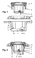
- the connecting terminals 8 of the flush-cup 4 preferably simultaneously form an electrical contacting device 9 for contacting a correspondingly designed electrical contacting device 2 of the electronics module 1.
- the support ring 5 is used for mounting the flush-mounted cup 4 in a flush-mounted box 18, which in a wall 19 is installed. Housing and support ring can also be integrally formed. For the introduction of the external lines into the interior of the housing 6, the latter is provided with at least one bottom-side opening 7, the size of which allows the straightening of lines.
- the electronics module 1 has holding devices 3 in order to be able to effect a mechanical attachment to the UP pot 4 in this way.
- Fig. 2 is a composite electrical / electronic flush-mounted installation device for home and building control or home communication technology shown. It can be seen the electrical contact between the contacting device 2 of the electronics module 1 and the contacting device 9 of the flush-mounting cup 4, wherein the contacting device 9 is integrated in the terminals 8. Furthermore, the necessary for the mechanical attachment of the holding devices 3 is shown in the support ring 5. Furthermore, the housing 6 of the concealed pot 4 and the cover 11 can be seen.
- the selection of the cover frame 11 can be made as desired from different installation equipment programs with different design and different colors.
- flush-mounted programs are available in different shapes, different colors and using different materials (eg plastic, stainless steel).
- the proposed electrical / electronic flush-mounted installation device is harmoniously integrated in a flush-mounted program and is not a "foreign body" with regard to sockets, switches, dimmers, tactile sensors, EIB / KONNEX devices, devices of home communication, motion detectors, etc.
- the proposed electrical / electronic flush-mounted installation device can be used in multiple combinations (eg 2-gang combination, 3-gang combination, 4-gang combination) together with switches, dimmers, etc.
- the electronics module 1 itself with a (fixed) cover frame 11 equip.
- Fig. 3 is a back view-of a concealed pot and in Fig. 4 is a front view of a concealed pot shown.
- a plurality of recesses 10 in the support ring 5 are introduced, through which the holding devices 3 of the electronics module 1 engage, so as to effect the mechanical attachment of the electronics module 1 on the UP pot 4.
- the installation of the electrical / electronic flush-mounted installation device of home and building control or home communications technology is as follows: First, in a pre-assembly of an attachment of the external lines to the terminals 8 of the UP-pot 4. Thereafter, the UP-pot 4 in the UP device box 18 introduced and attached to the UP device box 18, z. B. by spreading or by screws which engage through recesses in the support ring 5 in holes of the UP device box 18. Through the bottom-side opening 7 of the flush-cup 4, the external lines can then in a simple manner by means of a suitable tool, for. As a pair of needle nose pliers, sorted under the bottom of the UP-pot 4 / ordered / pushed.
Landscapes
- Engineering & Computer Science (AREA)
- Architecture (AREA)
- Civil Engineering (AREA)
- Structural Engineering (AREA)
- Casings For Electric Apparatus (AREA)
- Selective Calling Equipment (AREA)
- Details Of Indoor Wiring (AREA)
Description
- Die Erfindung betrifft ein elektrisches/elektronisches Unterputz-Installationsgerät der Haus- und Gebäudesystemtechnik oder der Hauskommunikationstechnik, insbesondere für den Kleinspannungs-Bereich.
- Wie in
Fig. 5 dargestellt, weisen übliche elektrische/elektronische Unterputz-Installationsgeräte im Bereich EIB/KONNEX (Europäischer Installationsbus / Standard für Haus- und Gebäudesystemtechnik der Konnex-Assoziation) und auch im Bereich der Hauskommunikationstechnik (Door Entry System, Türzugangssysteme) des Standes der Technik in der Regel einen Unterputzeinsatz respektive ein einen Tragring 14 aufweisendes Hauptmodul 13 auf, der respektive das in einer handelsüblichen, standardisierten, in einer Wand 19 installierten UP-Gerätedose 18 befestigt wird. Auf das Hauptmodul 13 wird dann ein Funktionsmodul 15 aufgesteckt, wobei das Funktionsmodul 15 beispielsweise in Form eines Tasterelements, Anzeigeelements, Kameramoduls usw. ausgebildet ist. Die elektrische Verbindung zwischen Hauptmodul 13 und Funktionsmodul 15 erfolgt durch eine Kontaktierungsvorrichtung 16, vorzugsweise ein Stift/Buchsen-Stecksystem. Das elektrische/elektronische Unterputz-Installationsgerät wird üblicherweise komplettiert durch einen Abdeckrahmen 11. - Aus der
EP 1 962 261 A2 ist ein Unterputz-Installationsgerät mit einem Gerätesockel bekannt, welcher über Anschlussklemmen an ein Netz anschließbar ist. - Aus der
DE 42 25 326 A1 ist eine Anschlussvorrichtung mit einem zugehörigen Bus-Adapter bekannt, welcher eine Bus-Ankopplung aufweist, die an gebäudeseitige BusZuleitungen anschlleßbar ist, wobei die Bus-Ankopplung mittels eines Tragringes an der Installationsdose befestigt wird. Der Tragring ist mit einer raumseitig offenen Aufnahme versehen, deren Innenabmessungen zumindest so groß sind, dass die Bus-Ankopplung in sie einsetzbar ist. Im Boden der Aufnahme befindet sich die Bus-Anschlussklemme. Die Bus-Anschlussklemme sowie die zugehörigen Stecker der Bus-Ankopplung sind so positioniert, dass mit dem Einstecken oder Herausziehen der Bus-Ankopplung In die oder aus der Aufnahme zugleich die elektrische Verbindung mit der Bus-Anschlussklemme hegestellt oder getrennt wird. - Aus der
EP 1 320 244 B2 ist eine modulare Hauskommunikationsanlage bekannt, bei welcher die Türstation und/oder die Wohnungsstation aus einem Hauptmodul sowie einem zugeordneten und elektrische Funktionselemente aufweisendem Funktionsmodul (z. B. Bedienelement) aufgebaut ist. Das Hauptmodul besteht nach Art eines Elektro-Installatlonsgarätes eines üblichen Gebäudeinstallationssystems aus einem sockelartigen, in eine normgemäße Elektro-Installationsdose einsetzbaren Geräte-Einsatz. Das Funktionsmodul ist elektrisch und mechanisch mit dem zugehörigen Hauptmodul verbindbar, indem es als Aufsatz unmittelbar auf den Geräte-Einsatz aufsteckbar ist. - Bei der Montage derartiger elektrischer/elektronischer Unterputr-Installatiansgeräte in der UP-Gerätedose besteht die Gefahr, dass die in der Regel dünnen/fitigranen externen Leitungen eingequetscht oder beschädigt werden. Bei der Demontage des Funktionsmoduls, z. B. bei Renovierungsarbeiten, verbleibt das Hauptmodul in der UP-Gerätedose in der Wand. Die zur Kontaktierung des Funktionsmoduls erforderliche Buchse ist dann in der Regel wandbündig und somit anfällig gegen Verschmutzung durch Farbe oder durch Leim beim Übertapezieren. Ein anschließendes Reinigen der meist filigranen Buchse ist schwer möglich und zeitaufwendig.
- Darüber hinaus sind elektrische/elektronische Unterputz-Installationsgeräte allgemein bekannt, bei denen das Hauptrnodul mit dem Funktionsmodul eine zur Montage in einer UP-Gerätedose geeignete Baueinheit, nachfolgend UP-Einsatz genannt, bildet.
- Bei der Montage derartiger elektrischer/elektronischer Unterputz-Installationsgeräte in der UP-Gerätedose besteht die Gefahr, dass die in der Regel dünnen/filigranen externen Leitungen eingequetscht oder beschädigt werden. Bei der Demontage eines solchen UP-Einsatzes müssen die externen Leitungen (z. B. die Busleitungen) vom UP-Einsatz getrennt werden und verbleiben in der UP-Gerätedose. Derartige auch als Monoblockgeräte bezeichnete elektrische/elektronische Unterputz-Installationsgeräte sind zumindest auf dem VDE-Markt nicht erwünscht / nicht zulässig.
- Der Erfindung liegt die Aufgabe zugrunde, ein optimiertes elektrisches/elektronisches Unterputz-Installationsgerät der Haus- und Gebäudesystemtechnik oder der Hauskommunikationstechnik anzugeben.
- Diese Aufgabe wird erfindungsgemäß gelöst durch ein elektrisches/elektronisches Unterputz-Installationsgerät der Haus- und Gebäudesystemtechnik oder der Hauskommunikationstechnik, umfassend einen Elektronikeinsatz und einen separaten, zur Montage in eine handelsübliche und/oder standardisierte UP-Gerätedose geeigneten UP-Topf, wobei der UP-Topf ein Gehäuse mit Tragring aufweist, wobei im Bodenbereich des Gehäuses Anschlussklemmen zum Anschluss externer Leitungen befestigt sind und wobei im Bodenbereich des Gehäuses eine elektrische Kontaktierungsvorrichtung befestigt ist, welche im montierten Zustand mit einer elektrischen Kontaktierungsvorrichtung des Elektronikeinsatzes zusammenarbeitet.
- Die mit der Erfindung erzielbaren Vorteile liegen insbesondere darin, dass sich die Kontaktierungsvorrichtung des UP-Topfes im Bodenbereich befindet, so dass nach Demontage des Elektronikeinsatzes vom UP-Topf ein Übertapezieren oder Überstreichen des in der UP-Gerätedose montierten UP-Topfes beim Renovieren möglich ist, ohne dass sich dabei das Risiko einer Verunreinigung der elektrischen Kontaktierungsvorrichtung ergibt. Des Weiteren besteht bei der Montage nicht die Gefahr, dass externe Leitungen eingequetscht oder beschädigt oder gelöst werden.
- Zweckmäßige Weiterbildungen der Erfindung sind in den Unteransprüchen gekennzeichnet.
- Die Erfindung wird nachstehend an Hand der in der Zeichnung dargestellten Ausführungsbeispiele erläutert. Es zeigen:
- Fig. 1
- ein elektrisches/elektronisches Unterputz-Installationsgerät der Haus- und Gebäudesystemtechnik oder der Hauskommunikationstechnik mit seinen drei Hauptkomponenten,
- Fig. 2
- ein zusammengesetztes elektrisches/elektronisches Unterputz-Installationsgerät der Haus- und Gebäudesystemtechnik oder der Hauskommunikationstechnik,
- Fig. 3
- eine Rückansicht eines UP-Topfes,
- Fig. 4
- eine Frontansicht eines UP-Topfes,
- Fig. 5
- ein elektrisches/elektronisches Unterputz-Installationsgerät der Haus- und Gebäudesystemtechnik oder der Hauskommunikationstechnik mit seinen drei Hauptkomponenten gemäß dem bekannten Stand der Technik.
- In
Fig. 1 ist ein elektrisches/elektronisches Unterputz-Installationsgerät der Haus- und Gebäudesystemtechnik oder der Hauskommunikationstechnik mit seinen drei Hauptkomponenten dargestellt. Diese drei Hauptkomponenten sind - ein Elektronikeinsatz 1, welcher sowohl Komponenten eines Hauptmoduls als auch Komponenten eines Funktionsmoduls umfasst,
- ein UP-Topf 4, welcher ein Gehäuse 6 mit Tragring 5 sowie Anschlussklemmen 8 für den Anschluss von externen Leitungen, z. B. Busleitungen, aufweist,
- optional ein Abdeckrahmen 11.
- Dabei bilden die Anschlussklemmen 8 des UP-Topfes 4 vorzugsweise gleichzeitig eine elektrische Kontaktierungsvorrichtung 9 für die Kontaktierung einer hierzu korrespondierend ausgebildeten elektrischen Kontaktierungsvorrichtung 2 des Elektronikeinsatzes 1. Der Tragring 5 dient zur Montage des UP-Topfes 4 in einer UP-Gerätedose 18, welche in einer Wand 19 installiert ist. Gehäuse und Tragring können auch einteilig ausgebildet sein. Für die Einführung der externen Leitungen in den Innenraum des Gehäuses 6 ist Letzteres mit mindestens einer bodenseitigen Öffnung 7 versehen, deren Größe das Richten von Leitungen zulässt. Der Elektronikeinsatzes 1 weist Haltevorrichtungen 3 auf, um auf diese Weise eine mechanische Befestigung am UP-Topf 4 bewirken zu können.
- In
Fig. 2 ist ein zusammengesetztes elektrisches/elektronisches Unterputz-Installationsgerät der Haus- und Gebäudesystemtechnik oder der Hauskommunikationstechnik dargestellt. Es ist die elektrische Kontaktierung zwischen der Kontaktierungsvorrichtung 2 des Elektronikeinsatzes 1 und der Kontaktierungsvorrichtung 9 des UP-Topfes 4 zu erkennen, wobei die Kontaktierungsvorrichtung 9 in die Anschlussklemmen 8 integriert ist. Des Weiteren ist das für die mechanische Befestigung notwendige Eingreifen der Haltevorrichtungen 3 in den Tragring 5 gezeigt. Ferner sind das Gehäuse 6 des UP-Topfes 4 sowie der Abdeckrahmen 11 zu erkennen. - Die Auswahl des Abdeckrahmens 11 kann nach Wunsch aus unterschiedlichen Installationsgeräte-Programmen mit unterschiedlichem Design und unterschiedlicher Farbgebung erfolgen. Derartige Unterputz-Programme sind in unterschiedlicher Formgebung, unterschiedlicher Farbgebung und unter Einsatz unterschiedlicher Materialien (z. B. Kunststoff, Edelstahl) verfügbar. Auf diese Weise wird das vorgeschlagene elektrische/elektronische Unterputz-Installationsgerät harmonisch in ein Unterputz-Programm integriert und stellt keinen "Fremdkörper" im Hinblick auf Steckdosen, Schalter, Dimmer, Tastsensoren, EIB/KONNEX-Geräte, Geräte der Hauskommunikation, Bewegungsmelder usw. dar. Des Weiteren kann das vorgeschlagene elektrische/elektronische Unterputz-Installationsgerät in Mehrfach-Kombinationen (z. B. 2fach-Kombination, 3fach-Kombination, 4fach-Kombination) zusammen mit Schaltern, Dimmern usw. eingesetzt werden. Ferner ergibt sich eine Vielzahl unterschiedlicher Kombinationsmöglichkeiten, z. B. im Hinblick auf mögliche Farb-Kombinationen.
- Selbstverständlich ist es zur Realisierung einer Einzelgeräte-Lösung und unter Verzicht der vorstehend angeführten Vorteile auch möglich, den Elektronikeinsatz 1 selbst mit einem (festen) Abdeckrahmen 11 auszurüsten.
- In
Fig. 3 ist eine Rückansicht-eines UP-Topfes und inFig. 4 ist eine Frontansicht eines UP-Topfes dargestellt. Es sind das Gehäuse 6 des UP-Topfes 4 mit bodenseitiger Öffnung 7, der mit dem Gehäuse 6 fest verbundene Tragring 5 und die Anschlussklemmen + Kontaktierungsvorrichtung 8 + 9 zu erkennen. Insbesondere sind mehrere Ausnehmungen 10 im Tragring 5 eingebracht, durch welche die Haltevorrichtungen 3 des Elektronikeinsatzes 1 greifen, um derart die mechanische Befestigung des Elektronikeinsatz 1 am UP-Topf 4 zu bewirken. - Die Installation des elektrischen/elektronischen Unterputz-Installationsgerätes der Haus- und Gebäudesystemtechnik oder der Hauskommunikationstechnik erfolgt wie folgt: Zunächst erfolgt bei einer Vormontage eine Befestigung der externen Leitungen an den Anschlussklemmen 8 des UP-Topfes 4. Danach wird der UP-Topf 4 in die UP-Gerätedose 18 eingeführt und an der UP-Gerätedose 18 befestigt, z. B. durch Spreizen oder durch Schrauben, welche durch Ausnehmungen im Tragring 5 in Bohrungen der UP-Gerätedose 18 greifen. Durch die bodenseitige Öffnung 7 des UP-Topfes 4 können die externen Leitungen dann in einfacher Weise mittels eines geeigneten Werkzeuges, z. B. einer Spitzzange, unter dem Boden des UP-Topfes 4 sortiert / geordnet / geschoben werden. Der für den Elektronikeinsatz 1 benötigte Bauraum ist somit frei von Leitungen und eine Beschädigung der externen Leitungen während der Montage wird wirksam verhindert. Anschließend erfolgt das Einführen des Elektronikeinsatzes 1 in den UP-Topf 4, wodurch selbsttätig eine mechanische Befestigung durch Eingriff der Haltevorrichtungen 3 des Elektronikeinsatzes 1 in die Ausnehmungen 10 des Tragrings bzw. des UP-Topfes 4 sowie eine elektrische Kontaktierung der Kontaktierungsvorrichtungen 2 + 9 erfolgt.
- Die für die elektrische Kontaktierung wichtigen Kontaktierungsvorrichtungen 2 / 9 können dabei wie folgt ausgebildet sein:
- Die Kontaktierungsvorrichtung 2 umfasst Stiftleisten, welche in Buchsen (= Kontaktierungsvorrichtung 9) der Anschlussklemmen 8 eingreifen.
- Die Kontaktierungsvorrichtung 2 umfasst metallische Druckfedern, welche unmittelbar die Schraubenköpfe oder zusätzliche Kontakte der Anschlussklemmen 8 oder auch zusätzliche, auf einer Leiterplatte des UP-Topfes 4 ausgebildete Kontakte kontaktieren (= Kontaktierungsvorrichtung 9).
- Die Kontaktierungsvorrichtung 2 umfasst Federkontaktstifte ("Pogo-Pins"), welche unmittelbar die Schraubenköpfe oder zusätzliche Kontakte der Anschlussklemmen 8 oder auch zusätzliche, auf einer Leiterplatte des UP-Topfes 4 ausgebildete Kontakte kontaktieren (= Kontaktierungsvorrichtung 9).
- Die Kontaktierungsvorrichtungen 2 + 9 sind als Stift-Buchsenleistenverbindung ausgebildet.
- Die Kontaktierungsvorrichtungen 2 + 9 sind in Direktstecktechnik einer Leiterplatte oder Flex-Leiterplatte ausgebildet.
- Der Elektronikeinsatz 1 kann unterschiedlich ausgebildet sein, je nachdem, welches Applikationsfeld betroffen ist. Der Elektronikeinsatz 1 kann beispielsweise ausgebildet sein
- als Audiogerät, wie z. B. UP-Radio, MP3-Player, Ipod Docking Station,
- als Videogerät, wie z. B. Kameramodul der Hauskommunikationstechnik oder Display,
- als Lichtmodul, insbesondere LED-Modul,
- als Jalousiesteuerung,
- als Timer-Bediengerät (Kurzzeitmesser),
- als Raumtemperaturregler für die Haus- und Gebäudesystemtechnik,
- als Tastsensor oder Bedienelement, z. B. zur Ansteuerung von Schaltaktoren für Beleuchtung,
- als Bewegungsmelder für die Haus- und Gebäudesystemtechnik,
- als Dimmer-Bediengerät,
- als Anzeigegerät für die Haus- und Gebäudesystemtechnik, z. B. für das Energiemanagement,
- als Funk- oder IR-Empfangsgerät für die Haus- und Gebäudesystemtechnik,
- als sicherheitstechnischer Sensor, wie z. B. Rauchmelder,
- als elektronischer Schalter.
-
- 1
- Elektronikeinsatz (Hauptmodul + Funktionsmodul)
- 2
- elektrische Kontaktierungsvorrichtung
- 3
- Haltevorrichtungen
- 4
- UP-Topf
- 5
- Tragring
- 6
- Gehäuse
- 7
- bodenseitige Öffnung
- 8
- Anschlussklemmen für externe Leitungen (z. B. Busleitungen)
- 9
- elektrische Kontaktierungsvorrichtung
- 10
- Ausnehmungen
- 11
- Abdeckrahmen
- 12
- -
- 13
- Hauptmodul
- 14
- Tragring
- 15
- Funktionsmodul
- 16
- elektrische Kontaktierungsvorrichtung
- 17
- -
- 18
- UP-Gerätedose
- 19
- Wand
Claims (9)
- Elektrisches/elektronisches Unterputz-Installationsgerät der Haus- und Gebäudesystemtechnik oder der Hauskommunikationstechnik, umfassend einen Elektronikeinsatz (1) und einen separaten, zur Montage in eine handelsübliche und/oder standardisierte UP-Gerätedose (18) geeigneten UP-Topf (4), wobei der UP-Topf (4) ein Gehäuse (6) mit Tragring (5) aufweist, wobei im Bodenbereich des Gehäuses (6) Anschlussklemmen (8) zum Anschluss externer Leitungen befestigt sind und wobei im Bodenbereich des Gehäuses (6) eine elektrische Kontaktierungsvorrichtung (9) befestigt ist, welche im montierten Zustand mit einer elektrischen Kontaktierungsvorrichtung (2) des Elektronikeinsatzes (1) zusammenarbeitet, dadurch gekennzeichnet dass das Gehäuse (6) zumindest eine bodenseitige Öffnung (7) zum Einführen von externen Leitungen aufweist, wobei die Größe der bodenseitigen Öffnung das Richten von Leitungen mittels eines geeigneten Werkzeugs zulässt.
- Elektrisches/elektronisches Unterputz-Installationsgerät nach Anspruch 1, gekennzeichnet durch einen separaten Abdeckrahmen (11).
- Elektrisches/elektronisches Unterputz-Installationsgerät nach Anspruch 1, dadurch gekennzeichnet, dass Gehäuse (6) und Tragring (5) einteilig ausgebildet sind.
- Elektrisches/elektronisches Unterputz-Installationsgerät nach Anspruch 1, dadurch gekennzeichnet, dass der Elektronikeinsatz (1) Haltevorrichtungen (3) aufweist, welche im montierten Zustand in Ausnehmungen (10) des Tragrings (5) bzw. des UP-Topfes (4) befestigend eingreifen.
- Elektrisches/elektronisches Unterputz-Installationsgerät nach einem der Ansprüche 1 - 4, dadurch gekennzeichnet, dass die Kontaktierungsvorrichtung (2) des Elektronikeinsatzes (1) Stiftleisten umfasst, welche in Buchsen der Anschlussklemmen (8) eingreifen.
- Elektrisches/elektronisches Unterputz-Installationsgerät nach einem der Ansprüche 1 - 4, dadurch gekennzeichnet, dass die Kontaktierungsvorrichtung (2) des Elektronikeinsatzes (1) metallische Druckfedern umfasst, welche unmittelbar die Schraubenköpfe oder zusätzliche Kontakte der Anschlussklemmen (8) oder auch zusätzliche, auf einer Leiterplatte des UP-Topfes (4) ausgebildete Kontakte kontaktieren.
- Elektrisches/elektronisches Unterputz-Installationsgerät nach einem der Ansprüche 1 - 4, dadurch gekennzeichnet, dass die Kontaktierungsvorrichtung (2) des Elektronikeinsatzes (1) Federkontaktstifte umfasst, welche unmittelbar die Schraubenköpfe oder zusätzliche Kontakte der Anschlussklemmen (8) oder auch zusätzliche, auf einer Leiterplatte des UP-Topfes (4) ausgebildete Kontakte kontaktieren.
- Elektrisches/elektronisches Unterputz-Installationsgerät nach einem der Ansprüche 1 - 4, dadurch gekennzeichnet, dass die Kontaktierungsvorrichtungen (2 + 9) des Elektronikeinsatzes (1) und des UP-Topfes (4) als Stift-Buchsenleistenverbindung ausgebildet sind.
- Elektrisches/elektronisches Unterputz-Installationsgerät nach einem der Ansprüche 1 - 4, dadurch gekennzeichnet, dass die Kontaktierungsvorrichtungen (2 + 9) des Elektronikeinsatzes (1) und des UP-Topfes (4) in Direktstecktechnik einer Leiterplatte oder Flex-Leiterplatte ausgebildet sind.
Applications Claiming Priority (1)
| Application Number | Priority Date | Filing Date | Title |
|---|---|---|---|
| DE201110008506 DE102011008506B4 (de) | 2011-01-13 | 2011-01-13 | Elektrisches/elektronisches Unterputz-Installationsgerät der Haus-und Gebäudesystemtechnik oder der Hauskommunikationstechnik |
Publications (3)
| Publication Number | Publication Date |
|---|---|
| EP2477290A2 EP2477290A2 (de) | 2012-07-18 |
| EP2477290A3 EP2477290A3 (de) | 2013-06-26 |
| EP2477290B1 true EP2477290B1 (de) | 2016-03-23 |
Family
ID=45375107
Family Applications (1)
| Application Number | Title | Priority Date | Filing Date |
|---|---|---|---|
| EP11009517.1A Active EP2477290B1 (de) | 2011-01-13 | 2011-12-02 | Elektrisches/elektronisches Unterputz-Installationsgerät der Haus- und Gebäudesystemtechnik oder der Hauskommunikationstechnik |
Country Status (6)
| Country | Link |
|---|---|
| EP (1) | EP2477290B1 (de) |
| CN (1) | CN102593772A (de) |
| DE (1) | DE102011008506B4 (de) |
| ES (1) | ES2578203T3 (de) |
| PL (1) | PL2477290T3 (de) |
| RU (1) | RU2597238C2 (de) |
Families Citing this family (19)
| Publication number | Priority date | Publication date | Assignee | Title |
|---|---|---|---|---|
| DE102012109478A1 (de) * | 2012-10-05 | 2014-04-10 | Ebm-Papst Mulfingen Gmbh & Co. Kg | Ventilator mit einer elektrischen Anschlusseinrichtung |
| DE102012023711A1 (de) * | 2012-12-05 | 2014-06-05 | Abb Ag | Unterputz-Steckdose mit Steckdosentopf |
| EP2802050B1 (de) * | 2013-03-15 | 2019-07-24 | Assa Abloy Ab | Universeller Halterungsring |
| DE102013006728A1 (de) * | 2013-04-19 | 2014-11-06 | Abb Ag | Elektronisches Unterputzgerät der Gebäude-Installationstechnik |
| EP2924815B1 (de) * | 2014-03-25 | 2020-07-08 | Berker GmbH & Co. KG | Elektrische Vorrichtung mit einer Montageschnittstelle und einen elektrischen Modul |
| DE102014004325A1 (de) * | 2014-03-26 | 2015-10-01 | Abb Ag | Unterputzeinsatz eines elektrischen Installationsgerätes |
| US9219358B2 (en) * | 2014-03-26 | 2015-12-22 | Elbex Video Ltd. | Intelligent support box for electric hybrid switches, power outlets and combinations thereof |
| CH710015A1 (de) * | 2014-08-26 | 2016-02-29 | Werner Obrist | Automatisierungsmodul für die Gebäudeautomation. |
| DE102015009756A1 (de) * | 2014-12-12 | 2016-06-16 | Abb Ag | Elektrisches Installationsgerät für ein busbasiertes Lichtruf- und/oder Kommunikationssystem |
| DE102015009755A1 (de) * | 2014-12-12 | 2016-06-16 | Abb Ag | Elektrisches Installationsgerät für ein busbasiertes Lichtruf- und/oder Kommunikationssystem |
| ES2832073T3 (es) * | 2014-12-17 | 2021-06-09 | Bticino Spa | Dispositivo de control de tipo empotrado para al menos un aparato de usuario eléctrico |
| US10311265B2 (en) | 2016-03-04 | 2019-06-04 | Assa Abloy Ab | Universal mounting ring |
| DE102016110104A1 (de) * | 2016-06-01 | 2017-12-07 | Abb Ag | Steckdoseneinsatz |
| ES2586596B1 (es) * | 2016-06-03 | 2017-07-21 | Simon, S.A.U. | Dispositivo de indicación, comunicación, alimentación eléctrica, medición y/o control de instalaciones |
| DE202016004646U1 (de) | 2016-07-28 | 2016-08-23 | Axel R. Hidde | Elektrisches Installationsgerät |
| ES2857898T3 (es) | 2018-03-02 | 2021-09-29 | Giersiepen Gira Gmbh | Dispositivo de instalación electrónica para la ingeniería de sistemas de edificios |
| FR3084781B1 (fr) | 2018-07-31 | 2021-05-14 | Legrand France | Support d’appareillage electrique et appareillage electrique associe |
| FR3102013B1 (fr) | 2019-10-11 | 2022-05-27 | Legrand France | Support d’appareillage électrique |
| CN111555081B (zh) * | 2020-03-24 | 2021-08-27 | 国网冀北电力有限公司廊坊供电公司 | 一种电力试验用轮压式插座及接线装置 |
Family Cites Families (23)
| Publication number | Priority date | Publication date | Assignee | Title |
|---|---|---|---|---|
| IT1079554B (it) * | 1977-01-31 | 1985-05-13 | Bonato Marcellino | Complesso di scatola con telaio portainterruttore portapresa per impianti elettrici in edifici |
| DE2901710A1 (de) * | 1979-01-17 | 1980-07-24 | Streif Ohg | Einbaudoseneinheit |
| DE3209823C2 (de) * | 1982-03-18 | 1985-01-31 | Aloys Mennekes Anlagengesellschaft, 5942 Kirchhundem | Steckdose, insbesondere Anbausteckdose, für Rundsteckvorrichtungen |
| DE8816234U1 (de) * | 1988-12-31 | 1989-03-16 | A. & H. Meyer GmbH Leuchten und Büroelektrik, 4926 Dörentrup | Elektrische Installationseinheit zum Einbau in Verkleidungswandungen |
| DE4225326C2 (de) * | 1992-07-31 | 1994-07-14 | Eberle Gmbh | Anschlußvorrichtung |
| EP0759651B1 (de) * | 1995-08-23 | 2000-12-20 | Siemens Aktiengesellschaft | Kontaktmodul, einpassend in Unterputzdosen |
| JPH10208821A (ja) * | 1997-01-27 | 1998-08-07 | Matsushita Electric Works Ltd | 埋込型情報コンセント |
| DE19812504B4 (de) * | 1998-03-21 | 2005-03-17 | Berker Gmbh & Co. Kg | Elektrisches Installationsgerät, insbesondere Lichtsignalgerät |
| US6175078B1 (en) * | 1998-11-30 | 2001-01-16 | Walker Systems, Inc. | Flush poke-through wiring fitting having a height adjustable data jack mounting bracket |
| FR2786940B1 (fr) * | 1998-12-04 | 2001-01-19 | Professional General Elect | Appareil electrique destine a etre mis en place dans un support |
| DE20010570U1 (de) * | 2000-06-14 | 2001-10-25 | Gira Giersiepen Gmbh & Co Kg, 42477 Radevormwald | Aufputzdose |
| DE10147944A1 (de) * | 2001-09-28 | 2003-04-24 | Siemens Ag | Installationsgerät |
| DE20122102U1 (de) | 2001-12-11 | 2004-04-22 | Gira Giersiepen Gmbh & Co. Kg | Hauskommunikationsanlage |
| AT411857B (de) * | 2002-07-23 | 2004-06-25 | Moeller Gebaeudeautomation Kg | Gehäuse |
| CN2777801Y (zh) * | 2005-03-15 | 2006-05-03 | 张大光 | 内置电子镇流器可更换式节能灯头的供电座 |
| DE102005016082B4 (de) * | 2005-04-08 | 2008-10-02 | Abb Ag | Unterputz-Installationsgerät mit Geräteeinsatz und Tragring |
| FI118447B (fi) * | 2005-11-17 | 2007-11-15 | Ensto Busch Jaeger Oy | Koje- tai jakorasia |
| DE102006017915B3 (de) * | 2006-04-18 | 2007-08-02 | Albrecht Jung Gmbh & Co. Kg | Elektrisches/elektronisches Installationsgerät |
| DE102007008625B4 (de) * | 2007-02-22 | 2010-03-18 | Abb Ag | Unterputz-Installationsgerät zur Informationsdarstellung |
| DE102007063584B4 (de) * | 2007-12-21 | 2017-08-24 | Merten Gmbh & Co. Kg | Elektrisches Installationsgerät |
| DE102008010550A1 (de) * | 2008-02-22 | 2009-08-27 | Abb Ag | Unterputzradio |
| DE102009008905A1 (de) * | 2009-02-12 | 2010-08-19 | S. Siedle & Söhne Telefon- und Telegrafenwerke OHG | Anschlußdose, Endgerät und Signalübertragungsvorrichtung |
| DE102009021449A1 (de) * | 2009-02-27 | 2010-09-09 | Abb Ag | Elektrisches Installationsgerät mit Ladegerät und Ablagemöglichkeit für Mobiltelefon |
-
2011
- 2011-01-13 DE DE201110008506 patent/DE102011008506B4/de active Active
- 2011-10-19 CN CN2011103403918A patent/CN102593772A/zh active Pending
- 2011-12-02 PL PL11009517.1T patent/PL2477290T3/pl unknown
- 2011-12-02 EP EP11009517.1A patent/EP2477290B1/de active Active
- 2011-12-02 ES ES11009517.1T patent/ES2578203T3/es active Active
-
2012
- 2012-01-12 RU RU2012101116/07A patent/RU2597238C2/ru not_active IP Right Cessation
Also Published As
| Publication number | Publication date |
|---|---|
| EP2477290A3 (de) | 2013-06-26 |
| DE102011008506A1 (de) | 2012-07-19 |
| RU2012101116A (ru) | 2013-07-20 |
| EP2477290A2 (de) | 2012-07-18 |
| CN102593772A (zh) | 2012-07-18 |
| DE102011008506B4 (de) | 2014-02-13 |
| PL2477290T3 (pl) | 2016-11-30 |
| RU2597238C2 (ru) | 2016-09-10 |
| ES2578203T3 (es) | 2016-07-21 |
Similar Documents
| Publication | Publication Date | Title |
|---|---|---|
| DE102011008506B4 (de) | Elektrisches/elektronisches Unterputz-Installationsgerät der Haus-und Gebäudesystemtechnik oder der Hauskommunikationstechnik | |
| EP2523273B1 (de) | Unterputz-Steckdose | |
| EP2211084B1 (de) | Leuchte, insbesondere Wandleuchte | |
| EP2751883B1 (de) | Unterputz-steckdose | |
| US20140273618A1 (en) | Junction box adapter and method of implementing an adapter in a junction box | |
| EP2912931B1 (de) | Gehäuse für an einer tragschiene anbringbare und aneinander anreihbare vorrichtungen, zugehöriges gehäuse-baukastensystem und vorrichtung mit einem solchen gehäuse | |
| DE102009043455A1 (de) | Anordnung zum Installieren von Geräten der Gebäudesystemtechnik | |
| EP3066903A1 (de) | Komponentenaufbausystem | |
| EP2360810A2 (de) | Elektrisches Unterputz-Installationsgerät zur Aufnahme eines mobilen Audio- und Kommunikationsgerätes | |
| EP2741374B1 (de) | Unterputz-Steckdose mit Steckdosentopf | |
| EP2223391A1 (de) | Elektrisches kontaktelement | |
| EP2684257B1 (de) | Steckverbinder | |
| EP2315318B1 (de) | Elektrische Schutzkontaktsteckdose | |
| EP3142196B1 (de) | Anschlussadapter für ein stromschieneneinspeisesystem und sein anordnungsverfahren | |
| DE102007063584B4 (de) | Elektrisches Installationsgerät | |
| DE202013007161U1 (de) | Elektrisches Installationsgerät mit Beleuchtungselement | |
| EP2043118B1 (de) | Elektrisches/elektronisches Installationsgerät | |
| EP2533432A2 (de) | WLAN-Repeater | |
| EP2351176B1 (de) | Elektrisches installationsgerät | |
| DE102024125415B3 (de) | Anordnung umfassend ein Installationsgerät und ein induktives Ladegerät, sowie Verfahren zum induktiven Laden eines Endgerätes | |
| DE10221292B4 (de) | Installationsgerät-Anschlußsystem | |
| DE102011012884B3 (de) | Eck-Adapter für Aufputz-Montage elektrischen/elektronischen Unterputz-Installationsmaterials | |
| EP4535586A1 (de) | Modulares aufputz-system für wandflächen | |
| DE202015102508U1 (de) | Installationsdose sowie Installationssystem | |
| EP3134944B1 (de) | Kopplungselement für ein elektrisch betriebenes gerät und damit ausgebildetes system |
Legal Events
| Date | Code | Title | Description |
|---|---|---|---|
| PUAI | Public reference made under article 153(3) epc to a published international application that has entered the european phase |
Free format text: ORIGINAL CODE: 0009012 |
|
| AK | Designated contracting states |
Kind code of ref document: A2 Designated state(s): AL AT BE BG CH CY CZ DE DK EE ES FI FR GB GR HR HU IE IS IT LI LT LU LV MC MK MT NL NO PL PT RO RS SE SI SK SM TR |
|
| AX | Request for extension of the european patent |
Extension state: BA ME |
|
| PUAL | Search report despatched |
Free format text: ORIGINAL CODE: 0009013 |
|
| AK | Designated contracting states |
Kind code of ref document: A3 Designated state(s): AL AT BE BG CH CY CZ DE DK EE ES FI FR GB GR HR HU IE IS IT LI LT LU LV MC MK MT NL NO PL PT RO RS SE SI SK SM TR |
|
| AX | Request for extension of the european patent |
Extension state: BA ME |
|
| RIC1 | Information provided on ipc code assigned before grant |
Ipc: H02G 3/08 20060101AFI20130522BHEP Ipc: H01R 13/73 20060101ALI20130522BHEP Ipc: H02G 3/12 20060101ALI20130522BHEP Ipc: H02G 3/18 20060101ALI20130522BHEP |
|
| 17P | Request for examination filed |
Effective date: 20130709 |
|
| GRAP | Despatch of communication of intention to grant a patent |
Free format text: ORIGINAL CODE: EPIDOSNIGR1 |
|
| INTG | Intention to grant announced |
Effective date: 20151211 |
|
| GRAS | Grant fee paid |
Free format text: ORIGINAL CODE: EPIDOSNIGR3 |
|
| GRAA | (expected) grant |
Free format text: ORIGINAL CODE: 0009210 |
|
| AK | Designated contracting states |
Kind code of ref document: B1 Designated state(s): AL AT BE BG CH CY CZ DE DK EE ES FI FR GB GR HR HU IE IS IT LI LT LU LV MC MK MT NL NO PL PT RO RS SE SI SK SM TR |
|
| REG | Reference to a national code |
Ref country code: GB Ref legal event code: FG4D Free format text: NOT ENGLISH |
|
| REG | Reference to a national code |
Ref country code: CH Ref legal event code: EP |
|
| REG | Reference to a national code |
Ref country code: AT Ref legal event code: REF Ref document number: 783988 Country of ref document: AT Kind code of ref document: T Effective date: 20160415 |
|
| REG | Reference to a national code |
Ref country code: IE Ref legal event code: FG4D Free format text: LANGUAGE OF EP DOCUMENT: GERMAN |
|
| REG | Reference to a national code |
Ref country code: DE Ref legal event code: R096 Ref document number: 502011009144 Country of ref document: DE |
|
| REG | Reference to a national code |
Ref country code: NL Ref legal event code: FP |
|
| REG | Reference to a national code |
Ref country code: SE Ref legal event code: TRGR |
|
| REG | Reference to a national code |
Ref country code: ES Ref legal event code: FG2A Ref document number: 2578203 Country of ref document: ES Kind code of ref document: T3 Effective date: 20160721 |
|
| REG | Reference to a national code |
Ref country code: LT Ref legal event code: MG4D |
|
| PG25 | Lapsed in a contracting state [announced via postgrant information from national office to epo] |
Ref country code: HR Free format text: LAPSE BECAUSE OF FAILURE TO SUBMIT A TRANSLATION OF THE DESCRIPTION OR TO PAY THE FEE WITHIN THE PRESCRIBED TIME-LIMIT Effective date: 20160323 |
|
| REG | Reference to a national code |
Ref country code: NO Ref legal event code: T2 Effective date: 20160323 |
|
| PG25 | Lapsed in a contracting state [announced via postgrant information from national office to epo] |
Ref country code: LV Free format text: LAPSE BECAUSE OF FAILURE TO SUBMIT A TRANSLATION OF THE DESCRIPTION OR TO PAY THE FEE WITHIN THE PRESCRIBED TIME-LIMIT Effective date: 20160323 Ref country code: LT Free format text: LAPSE BECAUSE OF FAILURE TO SUBMIT A TRANSLATION OF THE DESCRIPTION OR TO PAY THE FEE WITHIN THE PRESCRIBED TIME-LIMIT Effective date: 20160323 Ref country code: RS Free format text: LAPSE BECAUSE OF FAILURE TO SUBMIT A TRANSLATION OF THE DESCRIPTION OR TO PAY THE FEE WITHIN THE PRESCRIBED TIME-LIMIT Effective date: 20160323 |
|
| REG | Reference to a national code |
Ref country code: GR Ref legal event code: EP Ref document number: 20160401332 Country of ref document: GR Effective date: 20160729 |
|
| PG25 | Lapsed in a contracting state [announced via postgrant information from national office to epo] |
Ref country code: EE Free format text: LAPSE BECAUSE OF FAILURE TO SUBMIT A TRANSLATION OF THE DESCRIPTION OR TO PAY THE FEE WITHIN THE PRESCRIBED TIME-LIMIT Effective date: 20160323 Ref country code: IS Free format text: LAPSE BECAUSE OF FAILURE TO SUBMIT A TRANSLATION OF THE DESCRIPTION OR TO PAY THE FEE WITHIN THE PRESCRIBED TIME-LIMIT Effective date: 20160723 |
|
| PG25 | Lapsed in a contracting state [announced via postgrant information from national office to epo] |
Ref country code: SK Free format text: LAPSE BECAUSE OF FAILURE TO SUBMIT A TRANSLATION OF THE DESCRIPTION OR TO PAY THE FEE WITHIN THE PRESCRIBED TIME-LIMIT Effective date: 20160323 Ref country code: RO Free format text: LAPSE BECAUSE OF FAILURE TO SUBMIT A TRANSLATION OF THE DESCRIPTION OR TO PAY THE FEE WITHIN THE PRESCRIBED TIME-LIMIT Effective date: 20160323 Ref country code: PT Free format text: LAPSE BECAUSE OF FAILURE TO SUBMIT A TRANSLATION OF THE DESCRIPTION OR TO PAY THE FEE WITHIN THE PRESCRIBED TIME-LIMIT Effective date: 20160725 Ref country code: SM Free format text: LAPSE BECAUSE OF FAILURE TO SUBMIT A TRANSLATION OF THE DESCRIPTION OR TO PAY THE FEE WITHIN THE PRESCRIBED TIME-LIMIT Effective date: 20160323 |
|
| REG | Reference to a national code |
Ref country code: DE Ref legal event code: R097 Ref document number: 502011009144 Country of ref document: DE |
|
| PLBE | No opposition filed within time limit |
Free format text: ORIGINAL CODE: 0009261 |
|
| STAA | Information on the status of an ep patent application or granted ep patent |
Free format text: STATUS: NO OPPOSITION FILED WITHIN TIME LIMIT |
|
| PG25 | Lapsed in a contracting state [announced via postgrant information from national office to epo] |
Ref country code: DK Free format text: LAPSE BECAUSE OF FAILURE TO SUBMIT A TRANSLATION OF THE DESCRIPTION OR TO PAY THE FEE WITHIN THE PRESCRIBED TIME-LIMIT Effective date: 20160323 |
|
| PG25 | Lapsed in a contracting state [announced via postgrant information from national office to epo] |
Ref country code: BG Free format text: LAPSE BECAUSE OF FAILURE TO SUBMIT A TRANSLATION OF THE DESCRIPTION OR TO PAY THE FEE WITHIN THE PRESCRIBED TIME-LIMIT Effective date: 20160623 |
|
| 26N | No opposition filed |
Effective date: 20170102 |
|
| PG25 | Lapsed in a contracting state [announced via postgrant information from national office to epo] |
Ref country code: SI Free format text: LAPSE BECAUSE OF FAILURE TO SUBMIT A TRANSLATION OF THE DESCRIPTION OR TO PAY THE FEE WITHIN THE PRESCRIBED TIME-LIMIT Effective date: 20160323 |
|
| REG | Reference to a national code |
Ref country code: DE Ref legal event code: R119 Ref document number: 502011009144 Country of ref document: DE |
|
| PG25 | Lapsed in a contracting state [announced via postgrant information from national office to epo] |
Ref country code: MC Free format text: LAPSE BECAUSE OF FAILURE TO SUBMIT A TRANSLATION OF THE DESCRIPTION OR TO PAY THE FEE WITHIN THE PRESCRIBED TIME-LIMIT Effective date: 20160323 |
|
| REG | Reference to a national code |
Ref country code: FR Ref legal event code: ST Effective date: 20170831 |
|
| REG | Reference to a national code |
Ref country code: IE Ref legal event code: MM4A |
|
| PG25 | Lapsed in a contracting state [announced via postgrant information from national office to epo] |
Ref country code: LU Free format text: LAPSE BECAUSE OF NON-PAYMENT OF DUE FEES Effective date: 20161202 Ref country code: FR Free format text: LAPSE BECAUSE OF NON-PAYMENT OF DUE FEES Effective date: 20170102 |
|
| PG25 | Lapsed in a contracting state [announced via postgrant information from national office to epo] |
Ref country code: IE Free format text: LAPSE BECAUSE OF NON-PAYMENT OF DUE FEES Effective date: 20161202 Ref country code: DE Free format text: LAPSE BECAUSE OF NON-PAYMENT OF DUE FEES Effective date: 20170701 |
|
| PG25 | Lapsed in a contracting state [announced via postgrant information from national office to epo] |
Ref country code: CY Free format text: LAPSE BECAUSE OF FAILURE TO SUBMIT A TRANSLATION OF THE DESCRIPTION OR TO PAY THE FEE WITHIN THE PRESCRIBED TIME-LIMIT Effective date: 20160323 Ref country code: HU Free format text: LAPSE BECAUSE OF FAILURE TO SUBMIT A TRANSLATION OF THE DESCRIPTION OR TO PAY THE FEE WITHIN THE PRESCRIBED TIME-LIMIT; INVALID AB INITIO Effective date: 20111202 |
|
| PG25 | Lapsed in a contracting state [announced via postgrant information from national office to epo] |
Ref country code: MK Free format text: LAPSE BECAUSE OF FAILURE TO SUBMIT A TRANSLATION OF THE DESCRIPTION OR TO PAY THE FEE WITHIN THE PRESCRIBED TIME-LIMIT Effective date: 20160323 Ref country code: TR Free format text: LAPSE BECAUSE OF FAILURE TO SUBMIT A TRANSLATION OF THE DESCRIPTION OR TO PAY THE FEE WITHIN THE PRESCRIBED TIME-LIMIT Effective date: 20160323 |
|
| PG25 | Lapsed in a contracting state [announced via postgrant information from national office to epo] |
Ref country code: MT Free format text: LAPSE BECAUSE OF FAILURE TO SUBMIT A TRANSLATION OF THE DESCRIPTION OR TO PAY THE FEE WITHIN THE PRESCRIBED TIME-LIMIT Effective date: 20160323 |
|
| PG25 | Lapsed in a contracting state [announced via postgrant information from national office to epo] |
Ref country code: AL Free format text: LAPSE BECAUSE OF FAILURE TO SUBMIT A TRANSLATION OF THE DESCRIPTION OR TO PAY THE FEE WITHIN THE PRESCRIBED TIME-LIMIT Effective date: 20160323 |
|
| PGFP | Annual fee paid to national office [announced via postgrant information from national office to epo] |
Ref country code: DE Payment date: 20180913 Year of fee payment: 7 Ref country code: SE Payment date: 20181219 Year of fee payment: 8 Ref country code: PL Payment date: 20181127 Year of fee payment: 8 Ref country code: CZ Payment date: 20181130 Year of fee payment: 8 Ref country code: FI Payment date: 20181220 Year of fee payment: 8 |
|
| PGFP | Annual fee paid to national office [announced via postgrant information from national office to epo] |
Ref country code: BE Payment date: 20181217 Year of fee payment: 8 Ref country code: GB Payment date: 20181218 Year of fee payment: 8 Ref country code: CH Payment date: 20181218 Year of fee payment: 8 |
|
| PGFP | Annual fee paid to national office [announced via postgrant information from national office to epo] |
Ref country code: NO Payment date: 20181227 Year of fee payment: 8 Ref country code: ES Payment date: 20190123 Year of fee payment: 8 Ref country code: IT Payment date: 20181220 Year of fee payment: 8 |
|
| REG | Reference to a national code |
Ref country code: ES Ref legal event code: PC2A Owner name: ABB SCHWEIZ AG Effective date: 20190529 |
|
| REG | Reference to a national code |
Ref country code: CH Ref legal event code: PUE Owner name: ABB SCHWEIZ AG, CH Free format text: FORMER OWNER: ABB AG, DE |
|
| REG | Reference to a national code |
Ref country code: NO Ref legal event code: CHAD Owner name: ABB SCHWEIZ AG, CH |
|
| REG | Reference to a national code |
Ref country code: GB Ref legal event code: 732E Free format text: REGISTERED BETWEEN 20190718 AND 20190724 |
|
| REG | Reference to a national code |
Ref country code: BE Ref legal event code: PD Owner name: ABB SCHWEIZ AG; CH Free format text: DETAILS ASSIGNMENT: CHANGE OF OWNER(S), CESSION; FORMER OWNER NAME: ABB AG Effective date: 20190702 |
|
| REG | Reference to a national code |
Ref country code: NL Ref legal event code: PD Owner name: ABB SCHWEIZ AG; CH Free format text: DETAILS ASSIGNMENT: CHANGE OF OWNER(S), ASSIGNMENT; FORMER OWNER NAME: ABB AG Effective date: 20190926 |
|
| REG | Reference to a national code |
Ref country code: AT Ref legal event code: PC Ref document number: 783988 Country of ref document: AT Kind code of ref document: T Owner name: ABB SCHWEIZ AG, CH Effective date: 20190829 |
|
| REG | Reference to a national code |
Ref country code: FI Ref legal event code: MAE |
|
| REG | Reference to a national code |
Ref country code: NO Ref legal event code: MMEP |
|
| REG | Reference to a national code |
Ref country code: SE Ref legal event code: EUG |
|
| PG25 | Lapsed in a contracting state [announced via postgrant information from national office to epo] |
Ref country code: FI Free format text: LAPSE BECAUSE OF NON-PAYMENT OF DUE FEES Effective date: 20191202 Ref country code: CZ Free format text: LAPSE BECAUSE OF NON-PAYMENT OF DUE FEES Effective date: 20191202 |
|
| REG | Reference to a national code |
Ref country code: CH Ref legal event code: PL |
|
| REG | Reference to a national code |
Ref country code: BE Ref legal event code: MM Effective date: 20191231 |
|
| GBPC | Gb: european patent ceased through non-payment of renewal fee |
Effective date: 20191202 |
|
| PG25 | Lapsed in a contracting state [announced via postgrant information from national office to epo] |
Ref country code: SE Free format text: LAPSE BECAUSE OF NON-PAYMENT OF DUE FEES Effective date: 20191203 Ref country code: NO Free format text: LAPSE BECAUSE OF NON-PAYMENT OF DUE FEES Effective date: 20191231 Ref country code: GB Free format text: LAPSE BECAUSE OF NON-PAYMENT OF DUE FEES Effective date: 20191202 Ref country code: GR Free format text: LAPSE BECAUSE OF NON-PAYMENT OF DUE FEES Effective date: 20200707 Ref country code: IT Free format text: LAPSE BECAUSE OF NON-PAYMENT OF DUE FEES Effective date: 20191202 |
|
| PG25 | Lapsed in a contracting state [announced via postgrant information from national office to epo] |
Ref country code: LI Free format text: LAPSE BECAUSE OF NON-PAYMENT OF DUE FEES Effective date: 20191231 Ref country code: CH Free format text: LAPSE BECAUSE OF NON-PAYMENT OF DUE FEES Effective date: 20191231 Ref country code: BE Free format text: LAPSE BECAUSE OF NON-PAYMENT OF DUE FEES Effective date: 20191231 |
|
| REG | Reference to a national code |
Ref country code: ES Ref legal event code: FD2A Effective date: 20210601 |
|
| PG25 | Lapsed in a contracting state [announced via postgrant information from national office to epo] |
Ref country code: ES Free format text: LAPSE BECAUSE OF NON-PAYMENT OF DUE FEES Effective date: 20191203 |
|
| PG25 | Lapsed in a contracting state [announced via postgrant information from national office to epo] |
Ref country code: PL Free format text: LAPSE BECAUSE OF NON-PAYMENT OF DUE FEES Effective date: 20191202 |
|
| PGFP | Annual fee paid to national office [announced via postgrant information from national office to epo] |
Ref country code: AT Payment date: 20251222 Year of fee payment: 15 |
|
| PGFP | Annual fee paid to national office [announced via postgrant information from national office to epo] |
Ref country code: NL Payment date: 20251219 Year of fee payment: 15 |