EP2476636A1 - Vorrichtung zu Förderung eines sehr langen Artikels - Google Patents
Vorrichtung zu Förderung eines sehr langen Artikels Download PDFInfo
- Publication number
- EP2476636A1 EP2476636A1 EP12151005A EP12151005A EP2476636A1 EP 2476636 A1 EP2476636 A1 EP 2476636A1 EP 12151005 A EP12151005 A EP 12151005A EP 12151005 A EP12151005 A EP 12151005A EP 2476636 A1 EP2476636 A1 EP 2476636A1
- Authority
- EP
- European Patent Office
- Prior art keywords
- transferring
- article
- platform
- lifting
- transfer
- Prior art date
- Legal status (The legal status is an assumption and is not a legal conclusion. Google has not performed a legal analysis and makes no representation as to the accuracy of the status listed.)
- Granted
Links
- 238000000034 method Methods 0.000 claims abstract description 95
- 238000004804 winding Methods 0.000 claims abstract description 6
- 239000011435 rock Substances 0.000 description 96
- 238000003860 storage Methods 0.000 description 44
- 238000002360 preparation method Methods 0.000 description 19
- 238000010276 construction Methods 0.000 description 10
- 230000014759 maintenance of location Effects 0.000 description 9
- 230000007423 decrease Effects 0.000 description 6
- 230000003287 optical effect Effects 0.000 description 5
- 230000002093 peripheral effect Effects 0.000 description 4
- 229910000831 Steel Inorganic materials 0.000 description 3
- 239000010959 steel Substances 0.000 description 3
- 238000001514 detection method Methods 0.000 description 2
- 230000000694 effects Effects 0.000 description 2
- 238000010521 absorption reaction Methods 0.000 description 1
- 230000005540 biological transmission Effects 0.000 description 1
- 238000012790 confirmation Methods 0.000 description 1
- 238000005520 cutting process Methods 0.000 description 1
- 238000010586 diagram Methods 0.000 description 1
- 238000012423 maintenance Methods 0.000 description 1
- 239000002184 metal Substances 0.000 description 1
- 238000003892 spreading Methods 0.000 description 1
Images


Classifications
-
- B—PERFORMING OPERATIONS; TRANSPORTING
- B65—CONVEYING; PACKING; STORING; HANDLING THIN OR FILAMENTARY MATERIAL
- B65G—TRANSPORT OR STORAGE DEVICES, e.g. CONVEYORS FOR LOADING OR TIPPING, SHOP CONVEYOR SYSTEMS OR PNEUMATIC TUBE CONVEYORS
- B65G1/00—Storing articles, individually or in orderly arrangement, in warehouses or magazines
- B65G1/02—Storage devices
- B65G1/04—Storage devices mechanical
- B65G1/0407—Storage devices mechanical using stacker cranes
- B65G1/0421—Storage devices mechanical using stacker cranes with control for stacker crane operations
-
- B—PERFORMING OPERATIONS; TRANSPORTING
- B65—CONVEYING; PACKING; STORING; HANDLING THIN OR FILAMENTARY MATERIAL
- B65G—TRANSPORT OR STORAGE DEVICES, e.g. CONVEYORS FOR LOADING OR TIPPING, SHOP CONVEYOR SYSTEMS OR PNEUMATIC TUBE CONVEYORS
- B65G1/00—Storing articles, individually or in orderly arrangement, in warehouses or magazines
- B65G1/02—Storage devices
- B65G1/04—Storage devices mechanical
- B65G1/0442—Storage devices mechanical for elongated articles
-
- B—PERFORMING OPERATIONS; TRANSPORTING
- B66—HOISTING; LIFTING; HAULING
- B66B—ELEVATORS; ESCALATORS OR MOVING WALKWAYS
- B66B1/00—Control systems of elevators in general
- B66B1/34—Details, e.g. call counting devices, data transmission from car to control system, devices giving information to the control system
- B66B1/36—Means for stopping the cars, cages, or skips at predetermined levels
- B66B1/44—Means for stopping the cars, cages, or skips at predetermined levels and for taking account of disturbance factors, e.g. variation of load weight
-
- B—PERFORMING OPERATIONS; TRANSPORTING
- B65—CONVEYING; PACKING; STORING; HANDLING THIN OR FILAMENTARY MATERIAL
- B65G—TRANSPORT OR STORAGE DEVICES, e.g. CONVEYORS FOR LOADING OR TIPPING, SHOP CONVEYOR SYSTEMS OR PNEUMATIC TUBE CONVEYORS
- B65G2201/00—Indexing codes relating to handling devices, e.g. conveyors, characterised by the type of product or load being conveyed or handled
- B65G2201/02—Articles
- B65G2201/0214—Articles of special size, shape or weigh
- B65G2201/0217—Elongated
Definitions
- the present invention relates to a lengthy article conveying apparatus, which comprises a platform which is freely lifted along lifting masts, while being suspended and supported by a cord-like member and being guided and supported by the lifting masts; a transfer device which is provided on the platform and freely lifted with the platform in a united manner and which is arranged to mount and convey the lengthy article in a condition in which the longitudinal direction of the article becomes horizontal and to freely transfer the article between a target location to be transferred and the transferring device; a lifting driving means for driving the platform and the transfer device to be lifted by winding the cord-like member; and a control means for controlling the actuation of the lifting driving means and the transferring device.
- Such a lengthy article conveying apparatus is constituted such that the lengthy article is conveyed between the transfer device and the target transfer locations with different heights in the vertical direction with the aid of the transferring activity of the transfer device and the lifting activity of the platform.
- the apparatus is comprised of a stacker crane, which is used in an automated storage system, where a pair of storage racks having a plurality of article storages lengthwise and breadthwise for storing articles there and a consign board where the articles are loaded to or unloaded from the outside.
- the stacker crane performs the article loading work for conveying articles from the origin to the destination, considering the loading board as the target location origin and the storage as the target location destination and the article unloading work for conveying articles from the origin to the destination, considering the storage as the target location origin and the loading board as the target location destination.
- a conventional lengthy article conveying apparatus is disclosed in Japanese Patent Preliminarily Publication No. 2000-191114, where a lifted position detecting means is provided for detecting the lifted position of the platform.
- a control means for controlling the actuation of the lifting driving means and the transfer device performs the lifting procedure to position the platform at a lifting position for transferring in accordance with information detected by the lifting position detecting means, at which the outside end portion of the platform is received and held by a receiver provided at the target location for the transfer in the article transferring direction.
- the control means performs an article transferring procedure by which the transferring device is conveyed in a condition in which the end portion is received and held by the receivers provided at the target location for the transfer. (see Fig. 8 in Japanese Patent Preliminarily Publication No. 2000-191114 )
- This Patent Publication discloses an automated storage system being provided with a pair of article storage racks, which are arranged such that the article storing and retrieving directions face to each other.
- a stacker crane for conveying lengthy articles is provided being freely runnable along a transfer path formed between the pair of article storage racks.
- a transfer device is operated to transfer the article under a condition in which the outside end portionrs of the platform in the article transferring direction are received and held by receivers on the article storage constituting the target location for the transfer and by receiver on another article storage, an article storage in the other article storage rack facing the article storage constituting the target location for transfer.
- the load of articles to be conveyed by the transferring device or the load by the weight of the edge side portions of the platform itself acting upon the end portionr of the platform can be supported at the target location side for the transfer. Therefore, the platform can be supported in a stable manner by both the cord-like member and the target location for the transfer, and a smooth transfer of articles can be carried out by making the height of articles to be mounted and conveyed with the aid of the transfer device in the platform flush with the height of articles to be supported at the target location for the transfer.
- the operation of the lifting driving means is maintained in a suspended condition.
- the present invention is designed taking the above-mentioned situation into consideration and has a purpose to provide a lengthy article transferring apparatus by which lengthy articles can be transferred with respect to a target location for the transfer.
- the first characteristic structure of the lengthy article transferring apparatus is: a lengthy article transferring apparatus comprises a platform being freely lifted along a lifting mast in a condition in which said platform is suspended and supported by a cord-like member and guided and supported by the lifting mast, a transferring device being provided to the platform and being freely lifted along with the platform in a united manner and for mounting and transporting the lengthy article with its position so that its longitudinal direction is extended in a horizontal direction and for freely transferring the article between the platform and a target location for the transfer; a lifting driving means for lifting and driving the platform and the transferring device by winding said cord-like member; and a controlling means for controlling the actuation of the lifting driving means and the transferring device; wherein said apparatus further comprises a lifted position detecting means for detecting a lifted position of the platform; wherein said control means is constituted such that it performs a lifting operation for positioning the platform at a lifted position for transferring at which an outside end portion of the platform is received and supported by
- the first characteristic structure since the article is conveyed by the transferring device whilst the outside end portionr of the platform in the article transferring direction is held and supported by the receiver provided at the target location for the transfer, the load of the article to be transferred by the transfer device and the load acting upon the end portionr of the platform due to the weight of the end portionr of the platform itself can be supported at the side on the target location of the transfer, it is possible to support the platform with the aid of both the cord from and the article transfer location in a stable manner. Further, by making the height of the article to be mounted and transferred by the transferring device in the platform flush with the height of the article to be supported at the target location for the transfer, the transfer of the article can be smoothly performed.
- the lifting driving means actuates during the transferring procedure so that the variation in the lifted position of the platform, due to the variation in load acting upon the platform associated with the conveying of the article in the article transfer direction, is absorbed.
- the load acting upon the platform increases and the increase makes the elongation margin of the cord-like member, which suspends and support the platform, longer, and the lifted position of the platform would be shifted downwardly in accordance with the elongated margin of the cord-like member.
- the downward shift in the lifted position of the platform during the transferring procedure is absorbed by performing the lifted position adjustment procedure with the aid of the control means.
- the load acting upon the platform decreases and the decrease makes the elongation margin of the cord-like member, which suspends and support the platform, shorter, and the lifted position of the platform would be shifted upwardly in accordance with the elongated margin of the cord-like member.
- the upward shift in the lifted position of the platform during the transfer procedure is absorbed by performing the lifted position adjustment procedure with the aid of the control means.
- a lengthy article transferring apparatus can be realized by which lengthy articles can be appropriately transferred between the target location for the transfer and the apparatus can be prevented.
- the present inventors invented such a lengthy article conveying apparatus by which lengthy articles can be appropriately transferred between the transferring device and the target location for the transfer.
- the second characteristic structure of the lengthy article transferring apparatus is: the control means is constituted such that when a transferring operation for picking up an article is performed by the transferring operation, i.e. for transferring an article from the target location for the transfer to the transferring device, the control means determines if the platform is lifted down to the lower limit position, which is lower than the lifted position for transferring by a set height on the basis of information detected by the lifted position detecting means, and controls the actuation of the lifting driving means so as to lift up the platform by a set amount suitable for picking up an article when the platform arrives to the lower limit position, during the time when the transferring operation is performed.
- the second characteristic structure when the pick-up transferring operation of the articles from the target location for the transfer to the transferring device is performed, it is determined if the platform has reached the lower limit position in accordance with the shift in the actual lifted position of the platform during the transferring procedure. According to this determination, the downward movement of the platform can be properly obtained, and thus the shift in the lifted position of the platform can be appropriately absorbed.
- the platform cannot be lifted up until the platform reaches the lower limit position, the fluctuation of the platform in a vertical direction caused by frequently repeating the downward movement of the platform due to the increase of load of the article and the upward movement thereof due to the lifted position adjustment, can be restricted as much as possible.
- the shift in the lifted position of the platform can be appropriately absorbed in accordance with the actual amount of the downward movement of the platform, while the fluctuation of the platform in a vertical direction is restricted as much as possible.
- the third characteristic structure of the lengthy article transferring apparatus of the present invention is: the platform comprises a base frame to which said cord-like member is connected and a pair of end frames being extended into an article transferring direction from both sides of the base frame; wherein said transferring device is constituted to freely transfer the article to each of the target locations for the transfer, which are positioned at both sides thereof in the article transferring direction; wherein bodies to be held, which are received and supported by the receivers provided at the target locations for the transfer, are provided at each of the outer end portions of the pair of end frames in the article transferring direction; and wherein each of the pair of end frames are pivotably connected to the base frame so as to be freely fluctuated about the center of a horizontal axis intersecting to the article transferring direction.
- the third characteristic structure it is possible to transfer articles with respect to each of the target locations for the transfer, which are located both sides in the article transfer direction. Therefore, an automated storage system having a high capability for storing articles can be realized by applying the present invention to a stacker crane, which is runnable along a running path between a pair of article storing racks.
- each of the pair of end side frames is pivotally connected about the horizontal axis, which intersects to the article transfer direction, with respect to the base side frame in a freely fluctuating manner, even if the platform is pulled down due to an issue such as the lifted position adjustment not properly functioning under a condition in which, for example, the parts to be received at the outside end portions of the pair of edge side frames in the article transfer direction are received and supported by the receivers provided at the target locations for the transfer, each of the pair of edge side frames fluctuate about the horizontal axis with respect to the base frame, so that the problem of platform damage can be avoided.
- the fourth characteristic structure of the lengthy article transferring apparatus is: the apparatus further comprises a fluctuation detecting means for detecting the fact that at least one of the pair of end frames has fluctuated with respect to the base frame; wherein said controlling means is constituted such that it determines that the lifted position of the platform is not in alignment on the basis of information detected by the fluctuation detecting means in cases when at least one of the pair of end frames fluctuates with respect to the base frame.
- the fourth characteristic structure if at least one frame of the pair of end frames fluctuates with respect to the base frame during the time when the transferring device transfers articles due to any problem, such as when the lifted position adjustment procedure does not properly function, the fluctuation is detected by the fluctuation detecting means, and thereby the control means determines that the lifted position of the platform is not in alignment. Therefore, it is possible to take a countermeasure, such as an emergency stop of the actuation of the lengthy article transferring apparatus. In this way, the damage in the case when the end side frames fluctuate with respect to the base frame can be prevented from spreading.
- the firth characteristic structure of the lengthy article transferring apparatus is: the control means is constituted such that when transferring operation for setting down an article is performed by the transferring operation, i.e. for transferring an article from the transferring device to the target location for the transfer, the control means determines if the platform is lifted up to the upper limit position, which is higher than the lifted position for transferring by a set height on the basis of information detected from the lifted position detecting means, and controls the actuation of the lifting driving means so as to lift down the platform by a set amount appropriate for setting down an article when the platform arrives to the higher limit position, during the time when the transferring operation is performed.
- the platform when the setting-down transfer of articles from the transferring device to the target location for the transfer is performed, it is determined if the platform has reached to the upper limit position based on the shift in the actual lifted position of the platform during the transferring procedure. According to this determination, the upward movement of the platform can be properly obtained, and thus the shift in the lifted position of the platform can be appropriately absorbed.
- the platform is arranged such that it cannot be lifted down until it reaches the upper limit position.
- the fluctuation of the platform in a vertical direction which is caused by frequently repeating the upward movement of the platform due to the decrease of load of the article and the downward movement of the platform due to the lifted position adjustment procedure, can be restricted as much as possible.
- the shift in the lifted position of the platform can be appropriately absorbed in accordance with the actual amount of the upward movement of the platform, whilst the fluctuation of the platform in a vertical direction is restricted as much as possible.
- the sixth characteristic structure of the lengthy article transferring apparatus is: the platform comprises detecting sensors formed at the end portions of the platform for freely detecting the portion to be detected, which is provided at the target location for the transfer so as to correspond with the receivers, wherein the portions to be detected are arranged so as to be detected by the detecting sensors in a condition when the end portions of the platform have been received by the receivers; and wherein the control means is constituted such that it stops an actuation of the lifting driving means when the detecting sensors detect the portions to be detected, assuming that the platform is positioned at the lifted position for transferring.
- the actuation of the lifting driving means is stopped at the timing when the detecting sensor detects the portion to be detected, when it is corresponds to the receiver.
- the portions to be detected are so arranged such that the portions are detected by the sensors if the end portion of the platform is being held by the receivers.
- the platform is properly positioned at the lifting position for the transfer, i.e. where the end portion of the platform is held by the receivers.
- the platform suspended and supported by the cord-like member would be deformed such that the end portion are flexed downward due to the load of the article and the weight of the platform itself if the end portions thereof are not received and supported by the receivers since the degree of the deformation depends on the loads of the article or the size of the article to be loaded, if the lifted position of the platform is decided using the target location for the transfer only according to information detected by the lifted position detecting means, the end portion of the platform would not be appropriately received and supported by the receivers at the article transferring position.
- the seventh characteristic structure of the lengthy article transferring apparatus is: the platform comprises an upper frame and a lower frame, which are arranged in parallel and spaced apart in an upper and lower direction along the article transferring direction, and a plurality of inclined members arranged in the article transferring direction in a condition along a perpendicular plane connecting the upper and lower frames to each other to constitute a pair of truss frame portions, said truss frame portions are provided in a horizontal direction perpendicular to the article transferring direction with a space therebetween, and wherein the pair of truss frame portions are connected to each other with the aid of a plurality of horizontal members being arranged in the article transferring direction so as to constitute a truss frame in which an article containment space is formed for freely containing articles to be conveyed; and wherein the transferring device is constituted by a transferring conveyor which is mounted and supported by the plurality of horizontal members of the truss frame.
- the platform is comprised of a truss frame body comprising a pair of truss frame portions having a plurality of inclined members, arranged in the article transferring direction along a vertical plane being connected to each other with the aid of a plurality of horizontal members, the strength against a stress of the platform in a vertical direction is improved, and thus the deformation of the end portion of the platform by flexed downwardly is prevented in a condition in which the end portions are being not received and supported by the receivers.
- the transferring conveyor constituting the transferring device is mounted and supported by the plurality of horizontal members of the truss frame body, the transferring conveyor is mounted and supported by the truss frame body by which the end portion of the platform are not deformed easily by being flexed downwardly so much. Therefore, when the platform is lifted up during the prosecution of the article transferring operation, the deformation of the platform is restricted by the high strength of the truss frame body in addition to the absorption of the shift in the lifted position by the lifted position control operation, so the attitude of the transferring device during the transferring process is made stable and thus a smooth mounting and transferring of articles by the transferring device can be realized.
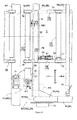
- a stacker crane 1 constituting a lengthy article conveying apparatus comprises a carriage 3 being runnable along a straight rail 2 provided on a plate 2a for installing the rail on a floor surface, a pair of front and rear lifting masts 4 stood from both front and rear end portions of the carriage in a running direction, a platform 6 which is freely lifted along the lifting masts 4 and between the pair of the lifting masts 4 in a condition in which the both front and rear end portions thereof in the running direction are guided and supported by the corresponding sides of the pair of lifting masts 4, respectively, and an upper frame 7 connecting the upper end portions of the pair of lifting masts 4.
- the platform 6 comprises a transferring device 5 constructed by a roller conveyor, by which a lengthy article W, which is longer in left and right direction viewed from the running direction of the carriage 3, can be freely mounted and transferred along its longitudinal direction.
- the transferring device 5 is provided on the platform 6 and can move with the platform 6 in a united manner; and it is constituted so as to mount and transfer the lengthy article W in a position that the longitudinal direction of the article is along a horizontal direction and to freely transfer the article between the device and the target location for the transfer.
- the stacker crane 1 performs an article conveying work for the article W as the target to be conveyed, i.e. receiving article W at the target location for the transfer origin and then transferring the article to the target location for the transfer destination, by the running actuation of carriage 3, the lifting actuation of platform 6, and the transferring actuation of transferring device 5.
- the target locations for the transfer are a loading board, which is not shown in the figures, and an article storage 61 of an article storing rack 60 (see Figs. 14 and 15 ), which will be explained later.
- a home position (HP) is set as the original position of the stacker crane 1, while at the other end portion of the rail 2 on the right side of Fig. 1 , an opposite position (OP) is set as the limit position for advancing the stacker crane.
- Fig. 1 is a left side view of the stacker crane 1
- Fig. 2 is a front view of the stacker crane 1 viewed from the OP side in the front and rear direction
- Fig. 3 is a cross plan view at the lower side thereof in an upper and lower direction.
- a pair of guide roller units 10 having a pair of left and right upper guide rollers 9, 9 are separately provided in a front and rear direction so as to protrude in the left side direction.
- the guide rollers 9, 9 are urged against both lateral side surfaces of the upper rail 8, which is suspended and supported by a rail support member provided on the ceiling, being parallel to the rail 2.
- upper idler sprockets 11 are provided, respectively.
- the upper idler sprockets 11 are composed of two pairs of sprockets, in each of which a pair of two series of sprockets is provided (see Figs. 4 and 6 ).
- the platform 6 is suspended and supported by a lifting metal chain 12 defined as a cord-like member.
- a lifting metal chain 12 defined as a cord-like member.
- the lifting chain 12 connected to the end portion at the OP side and the lifting chain 12 connected to the end portion at the HP side are composed of a set of tow chains, respectively, which are adj acent to each other in the left and right direction, so as to be able to support a sufficient lifting load (see Fig. 6 ).
- the set of lifting chains 12 connected to the OP side end portion of the platform 6 are wound over a return idler sprocket 37 on the platform side (will be explained below); an end of one of the chains 12 being upwardly guided by the sprocket 37 is fixedly connected to the lower surface of the upper frame 7; and the end of another one of the chains 12 also being upwardly guided by the sprocket 37 is wound over a set of corresponding sprockets in the front and rear direction among those of upper idler sprockets 11, which are provided at two positions on the HP side of the upper frame 7, and this chain is further wound over the upper idler sprocket 11 at the most OP side.
- the upper idler sprockets 11 provided at the two positions on the HP side are arranged such that the one set of two lifting chains 12 is wound over only one of the sets of sprockets out of the two sets of sprockets, i.e. four sprockets in total, whose positions in the axis center direction correspond to those of the set of two lifting chains 12 which should be wound over it.
- the upper idler sprockets 11 provided at two positions on the OP side are arranged such that two sets of lifting chains 12, i.e. four chains in total, are wound over the two sets of sprockets, i.e. four sprockets in total, respectively.
- the two sets of lifting chains 12 wound over the driving sprocket 13 are guided upwardly toward the upper idler sprocket 11, which is secondly on the OP side of the upper frame 7, and then wound over the upper idler sprocket 11.
- the two sets of lifting chains 12 wound over the upper idler sprocket 11 are downwardly guided through the inside of the OP side mast toward a counter weight side return idler sprocket 29, which suspends and supports a counter weight 22 provided inside of the OP side mast so as to be freely lifted therethrough. Then the sets of chains 12 are guided upwardly through the inside of the OP side mast to be connected to the chain connecting portions on the upper frame 7.
- the lifting motor M2 functions as a lifting driving means for winding the lifting chains 12 defined as the cord-like member to lift the platform 6 and the transfer device 5.
- the pair of lifting chains for suspending and supporting the platform 6 is composed of one set of two chains, respectively, so that the load acting on one of the chains is reduced.
- the winding path of the lifting chains 12 goes through via the counter weight side return idler sprocket 29, which is freely movable in a vertical direction, and the platform side return idler sprocket 37, so that the lifting load acting on the chains of each set can be reduced.
- a pair of running wheels 14 is provided, which run on the rail 2.
- the wheel positioned at the OP side end portion of the carriage 3 is a driving wheel 14a, which is driven by the running motor M1, while the wheel at the HP side end portion of the carriage 3 is an idling wheel 14b, which is freely idled as the running of the carriage 3.
- the carriage 3 is arranged such that an OP side mast supporting frame 16a, which supports the lowest end of the OP side mast 4a, is connected to an OP side end portion of a main frame 15.
- a pair of left and right intermediate frames 15a and 15b in a front and rear direction are connected to the main frame at a plurality of front and rear positions; and an HP side mast supporting frame 16b for supporting the lowest end of the HP side mast 4b is connected to the HP side end portion of the main frame 15.
- the front and rear running wheels 14 are supported by the pair of front and rear mast supporting frames 16 via the wheel support frame 17.
- the driving wheel 14a is rotatably supported by the driving wheel frame 17a, and the driving wheel frame 17a is connected to the OP side mast support frame 16a.
- the idling wheel 14b is rotatably supported by the idling wheel frame 17b and the idling wheel frame 17b is connected to the HP side mast support frame 16b.
- Each of the pair of front and rear mast support frames 16 comprises a flange 18 for attaching a mast, to which the connecting portion formed at the lowest portion of the lifting mast 4 is fixed by means of bolts.
- a running rotary encoder RE1 (see Fig. 10 ) is attached to the idling wheel frame 17b as a running position detecting means, which outputs pulses corresponding to the rotation amount of the idling wheel 14a.
- Running motor attaching bracket 27 and lifting motor attaching bracket 28 are fixed to the flange 18 for attaching the OP side mast by means of bolts; and onto these brackets running motors M1 and M2 are fixed in a condition in which running motor M1 is located at the right side of carriage 3 and lifting motor M2 at the left side thereof.
- a pair of left and right lower guide rollers 20 are provided via brackets, being urged against the both lateral side surfaces of the rail 2.
- a pair of front and rear guides 19 are provided on the lateral left side portion of carriage 3 for preventing a the carriage from falling down, which has a horizontal plate which is closely contacted to the upper and lower sides of an anchor pipe (not shown) being arranged in parallel to the rail 2 on the floor surface.
- a ladder 21 is provided acro the lower end to the upper end, on which an operator rides for the purpose of maintenance.
- controlling wire lines or power supply wire lines between platform 6 and carriage 3 are housed in a lifting cable guide, which is provided in a vertical direction at a right side of the OP side lifting mast 4a.
- One of the ends of the lifting cable guide is connected to the OP side lifting mast 4a and the other one is to platform 6.
- the lifting cable guide is deformed as platform 6 is lifted, so the movement of the control wire line or the power supply wire line is guided by the deformation.
- control wire line or the power supply wire line between the ground and carriage 3 of the stacker crane 1 is housed in a running cable guide provided along the side of rail 2; and the one of the ends of the running cable guide is connected to the floor surface side and the other end is to carriage 3.
- a ground side controller C which will be explained later, and stacker crane 1 can communicate control information, and an electric power can be supplied to the stacker crane from a ground side power supply device.
- the platform 6 comprises a base frame 30, to which the lifting chains 12 are connected, and a pair of end frames 50.
- the pair of end frames 50 is composed of a left end frame 50L and a right end frame 50R and they are extended from both sides of the base frame 30 in the article transferring direction, i.e. the left and right direction.
- the base frame 30 is configured by a pair of front and rear up-right portions 31, 31 and a horizontal connecting member 32.
- the up-right portion is constituted by longitudinal steel plates and a lateral steel plate and a cylindrical inclined member, which are welded to each other, and the horizontal connecting member 32 connects the pair of up-right members 31, 31 to each other at left and right end portions and an intermediation portion of the pair of up-right members 31, 31.
- the up-right members 31, 31 have the same constitution, although the front and rear sides are different, the pair will be explained by the OP side up-right portion 31 as a representative of them.
- the up-right portion 31 comprises a plurality of lifting guide rollers 33, which are urged against the left and right both side surfaces of the lifting mast 4 at an outer end portion of the platform 6 in its front and rear direction.
- a bogie 34 comprises a pair of lifting guide rollers 33, which are provided rotatably about the horizontal shaft in a vertical direction.
- the bogie 34 is pivotably connected about the horizontal shaft in a freely fluctuated manner with the aid of a bracket 35 for attaching the bogie. It should be noted that four bogies are provided to the up-right portion 31 at the left, right, top and bottom on the OP side thereof, respectively.
- the pair of lifting guide rollers 33 are urged at two up and down locations in a vertical direction via the bogies 34.
- the up-right portion 31 includes a pair of upper and lower guide rollers 36, which are urged against the HP side surfaces of the OP side mast 4a, for restricting the movement of the platform 6 in the front and rear direction.
- a pair of left and right bogies 34 is provided for the pair of up-right portions 31, respectively, in total two pair of bogies 34, in a condition in which the pairs of bogies are separated in the upper and lower direction from each other, so that the platform 6 can be lifted along the lifting mast 4, whilst keeping the front and rear viewing attitude of the base frame 30.
- a pair of up and down guide rollers 36 is provided for the pair of front and rear up-right portions 31, respectively, the platform 6 can be lifted along the lifting mast 4 under a condition in which the position of the base frame 30 is in a front and rear direction restricted between the pair of front and rear lifting mast 4.
- a fixing chain 70 for detecting the lifted position in a upper and lower direction being parallel to the front and rear roller urging plate.
- an increment type lifting rotary encoder RE1 is provided where the rotating axis thereof is directed in a lateral direction, and a sprocket is connected to the rotating axis to be freely rotated integrally to the axis of the rotary encoder RE2, whilst being threaded to the fixing chain 70 for detecting the lifted position.
- a lifting controller HV which will be explained later, manages the counted value of the number of the output pulses from the rotary encoder RE2, resets the counted value of the number of the output pulses at the lifting home position, which is set at the lowest end of the lifting range of the platform 6, and detects the lifted position of the platform 6 by counting the number of the output pulses from the lifting rotary encoder RE2 after setting the platform at the home position.
- the lifting rotary encoder RE 2 functions as a lifted position detecting means for detecting the lifted position of the platform 6.
- the pair of front and rear up right portions 31 comprises platform side return idler sprockets 37, respectively, on the intermediate portions in the left and right direction.
- the platform side return idler sprocket 37 is rotatably supported by an idler support frame 38, which can be freely lifted up and down being energized downwardly with the aid of a compressed spring (not shown), for example.
- a link mechanism 40 having an unti-drop mechanism 39 is connected.
- the idler support frame 38 is moved downward with respect to the up right portion 31.
- a pair of clipping blocks 41 coupled to the link mechanism 40, is operated in a fluctuated manner about the center of the lateral axis thereof. Therefore, the pair of clipping blocks holds a protruded plate, which is provided along the platform 6 side surface of the lifting mast 4 (for instance, the HP side surface of OP side mast 4a) in an up and down direction being protruded toward the platform 6 side.
- the fluctuated axis center of the pair of clipping blocks 41 is arranged such that as the platform 6 is lifted down, the pair of clipping blocks 41 is fluctuated to the clipping side of the protruded plate 42, so that the downward movement of the platform 6 is controlled so as to prevent the dropping thereof.
- a limit switch which is always ON, is provided on each of the pair of front and rear up right portions 31; and it becomes OFF when the lifting chain 12 is cut out.
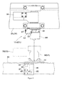
- each of the pair of end frames 50 is pivotably connected to the base frame 30 about the center of the horizontal axis which intersects to the left and right direction, i.e. the article transferring direction, in a fluctuatable manner.
- the base frame 30 and the pair of left and right end frames 50 are pivotably connected by the pivotable connecting axis 43 at an upper position thereof; the end frames 50 are extended from the base frame 30 in the left and right direction, i.e. an article transferring direction, by the urging of the frames 50 against the lower position of the base frame 30.
- a pair of truss frames 54 is provided being spaced in the front and rear direction, which is a horizontal direction intersecting to the article transferring direction.
- the truss frame 54 is comprised of the upper frame 51 and the lower frame 52 arranged to be spaced in an upper and lower direction and to be parallel to each other along the left and right direction (the article transferring direction), and a plurality of inclined members 53 arranged in a left and right direction along the vertical surface.
- the end frame 50 is constituted by a pair of such truss frames 54 and a plurality of horizontal members 55 being arranged in a left and right direction to connect the truss frames 54 to each other at a plurality of positions.
- the tru frames form an article containing space Z, in which articles W to be conveyed can be freely contained.
- an upper horizontal member 55U for connecting the upper frames 51 and a lower horizontal member 55L for connecting the lower frames 52 are provided.
- the upper horizontal members 55U adjacent to each other are connected to each other by connecting their opposite ends in a front and rear direction with the aid of horizontal brace 56.
- a base side connector 44 and a base side urging plate 46 are welded.
- an end side connector 45 and an end side urging plate 47 are welded.
- the base frame 30 and the end frame 50 are pivotably connected by a knuckle joint system at the pivot connecting axis 43 under a condition in which the protruded plate formed with the end side connector 45 is held between the pair of front and rear connecting plates formed with the base side connector 44.
- each of the pair of end frames 50 is pivotably connected to the base frame 30 in a fluctuatable manner about the center of the horizontal axis which intersects to the left and right direction, i.e. the article transferring direction.
- the base side urging plate 46 and the end side urging plate 47 By urging the base side urging plate 46 and the end side urging plate 47, the fluctuation to the lower side of the left side frame 50L and the right side frame 50R is restricted, so that their position to the base frame 30 is maintained.
- Fluctuation detecting sensors SY are provided to detect the fluctuation of the pair of frames 50 with respect to the base frame 30 about the center of horizontal axis.
- the fluctuation detecting sensor SY is composed of a photo micro sensor having an optical axis along the front and left direction. As shown in Fig. 5 , the fluctuation detecting sensors SY are supported by fluctuation sensor attaching brackets 48, respectively, which are attached to the left and right end portions of the pair of upright portions 31, respectively.
- a body 69 to be detected for fluctuation which is comprised of a folded plate member, is provided.
- a tip portion of the body 69 is detected by the corresponding fluctuation detecting sensors SY at two positions in front and rear of the lower end portion. Then, when any one of the pair of end frames 50 is fluctuated about the pivotably connecting axis 43, the tip portion of the body 69 becomes out of the optical axis being extended along the front and rear direction of the fluctuation detecting sensors SY, so that the fluctuation detecting sensor SY in a detecting condition is switched to a non-detecting condition, and therefore it is possible to detect the fluctuation of at least one of the pair of end frames 50 with respect to the base frame 30.
- the stacker crane 1 comprises four fluctuation sensors SY as the fluctuation detecting means for detecting the fluctuation of at least one of the end frames 50 with respect to the base frame 30.
- the transfer device 5 is mounted and supported on the upper surface of the lower horizontal member 55L.
- the transfer device 5 comprises a plurality of rotating rollers 72 having a sprocket 71 at one of the ends thereof in a condition in which the rotating center of axes are along the front and rear direction.
- conveyer roller bearings 74 are provided, on which both the ends of a plurality of rotating rollers 72 are rotatably supported.
- the transferring device 5 is comprised of three parts, i.e. a first part arranged on the base frame 30, a second part on the right side frame 50R, and a third part on the left side frame 50L. To each part, a rotating roller 72 is provided.
- the base side roller 72M arranged on the base frame 30 is supported by a pair of front and rear frames 73M which are provided across over the pair of left and right horizontal connecting members 32 of the base frame 30.
- the left end side roller 72L arranged on the left end frame 50L is supported by a pair of front and rear left side frames 73L which are arranged inside on the upper portion of the plurality of lower horizontal members 55L for connecting the pair of front and rear lower frames 52 of the left side frame 50L, in a front and rear direction.
- the right end side roller 72R arranged on the right end frame 50R is supported by a pair of front and rear right side frames 73R which are arranged inside on the upper portion of the plurality of lower horizontal members 55L for connecting the pair of front and rear lower frames 52 of the right side frame 50R.
- a transfer motor M3 is provided being supported by a transfer motor support frame 74.
- a driving sprocket 76 is rotatably connected so as to be united thereto.
- a pair of guide sprockets 77 are provided on the OP side frame out of the pair of front and rear center frames 73M in a freely idling manner.
- a tension sprocket 81 is provided via a bracket, such that the tension sprocket is located at the left end portion of the OP side right frame 73L and the position of the sprocket in the article transferring direction (left and right direction) is freely adjustable with the aid of adjuster bolt 82.
- a driven sprocket whose attachment portion is fixed is rotatably provided between the end roller 72T located at the end portion 50T of the right side frame 50R and the rotating roller 72R being adjacent to the roller 72T.
- a ring-shaped driving chain 78 is wound over the driving sprocket 76 arranged in the center of the transfer device 5 in left and rear direction, a pair of guide sprockets 77, a tension sprocket 81 arranged on the left end of the transferring device in a left and right direction, and the driven sprocket arranged on the right end of the driving device in the left and right direction.
- the upper wound part of the ring-like driving chain 78 is engaged to the lower sides of the sprockets 71 of the base side roller 72M, the left end side roller 72L and the right end side roller 72R, respectively; and therefore, when the driving chain 78 is would and driven by the transferring motor M3, the plurality of rotation rollers 72 are rotated and driven at the same time.
- the end rollers 72T arranged at the end portions 50T of the left side frame 50L and the right side frame 50R, out of the plurality of rotation rollers 72, are supported by the conveyer roller bearing 74 in a freely idling manner.
- the platform 6 is constituted as a truss frame, which comprises a pair of end frames 50 comprised of the left side frame 50L and right side frame 50R.
- the transferring device 5 is constituted by a transferring conveyor mounted and supported on the plurality of lower horizontal members 55L as the plurality of horizontal members of the left end frame 50L as the truss frame and the right end frame 50R as the truss frame.
- the transferring device 5 comprises a pair of guide rollers 79 arranged in the width direction (front and rear direction) at a plurality of positions in the article transferring direction (left and right direction).
- Guide roller supporting plates 80 for supporting a pair of guide rollers 79 are connected to a plurality of positions of the pair of front and rear conveyor frames 73 in the article transfer direction, respectively.
- On the bottom surface of the article W two concave grooves are formed in a width direction, which are extended over the longitudinal full length of the article, so that the plurality of pairs of the guide rollers 79 are engaged into the two concave grooves to guide the articles W to be conveyed by the transferring device 5 along the article transferring direction.
- a left end limit switch RS 1 is provided, which acts on the bottom surface of the article W to detect the existence of the article at the left end.
- the switch RS 1 can detect if the front end and the rear end of the article W being conveyed by the transferring device 5 in the article transferring direction has passed over the installed position of the switch.
- a right end limit switch RS2 is provided on the guide roller supporting plate 80, which is arranged on the end portion 50T of the right side frame 50R, in the same manner (see Fig. 10 ).
- a central sensor group SG constituted of a plurality of transmission optical sensors is provided.
- This sensor group emits a light in a horizontal detection to a portion to be detected, which is for detecting a proper transferring position, provided on the center of the bottom surface of the article W in its longitudinal direction (see Fig. 10 ).
- the stacker crane 1 is arranged so as to reciprocally move on the path between a pair of left and right article storage racks 60, which are arranged in the left and right direction.
- Each of the article storage rack 60 comprises article storages 61 lengthwise and breadthwise for freely storing lengthy articles W with a position that the longitudinal direction thereof is along the front and rear direction of the rack (a depth direction of the rack).
- a rack side conveyor 62 having its transferring direction in the rack front and rear direction is provided.
- a rack side conveyor controller (not shown) for controlling the actuation of the plurality of rack side conveyors 62 independently communicates with a ground side controller 1, which commands the article conveying work to the stacker crane 1, so that the rack side conveyor 62 in the transfer target article storage 61 actuates to transfer the article in a direction for transferring the article when transferring the article W between the storage 61 and the stacker crane 1.
- a horizontal connecting member 63 comprised of an H-shaped steel is provided at the front side of the article storage racks 60 for connecting the plurality of rods being adjacent to each other of the article storage racks 60 at the front side of the racks.
- a pair of receivers 64 which are arranged as convex portions each having an opening upwardly, are separately provided in the rack width direction. The positions where the receivers are provided correspond to the article storages 61, respectively, in the rack width direction.
- the pair of receivers 64 are fixed to the upper surface of the horizontal connecting member 63 by means of bolts so as to be protruded upwardly.
- the distance between the pair of receivers 64 is the same as that between the pair of front and rear rock arms 58 provided on the stacker crane 1 side.
- the mount and transfer surfaces of the rack side conveyors 62 of the article storages 61 and the transferring device 5 of the stacker crane 1 are coincide to each other.
- the stacker crane 1 performs the article transferring work for installing the article W using the loading plate (not shown) as the target location for the transfer of the origin and any one of the article storages 61 of the pair of article storage racks 60 as the target location for the transfer of the destination, and the article transferring work for uninstalling the article W using any one of the article storages 61 of the pair of article storage racks 60 as the target location for the transfer of the origin and using the loading plate as the target location for the transfer of the designation. That is to say, the transfer device 5 can freely transfer the article W to the target locations for the transfer located at both sides in the article transferring direction.
- the platform 6 When the stacker crane 1 transfers the article W between the stacker crane and the article storage 61, the platform 6 is located at the lifting position for the transfer, where the pair of front and rear rock arms 58 provided at the outside end 50T of the platform 6 in the article transferring direction are received and supported by the pair of receivers 64 in the article storage 61, which is a target for the transfer; then the transferring device 5 actuates to transfer the article under a condition in which the pair of front and rear rock arms 58 on the outside end portion 50T of the platform 6 in the article transferring direction are received and supported by the receivers 64 of the article storages 61.
- the transferring device 5 is actuated to transfer the article, in a condition in which the pair of front and rear rock arms 58 provided on each of the left and right end portions 50T of the platform 6 are received and supported by the pair of receivers 64 provided each of the target article storage 61 and the article storage 61 corresponding thereto.
- a pair of load plates are provided both sides of the path of the stacker crane 1, and each of the pair of load plates comprises a loading plate transferring device comprised of a roller conveyor and a pair of receivers 64, in the same manner as the article storages 61.
- the transferring device 5 actuates to transfer the article W under the condition in which the pair of front and rear rock arms 58 of the left and right end portions 50T are respectively received and supported by the pair of receivers 64 of the pair of loading plates, respectively.
- the stacker crane 1 has rock arms 58 as members to be received at the outside end portions 50T of each of the pair of end frames 50 in the article transferring direction, which are received and supported by the receivers 64 provided on the target location for the transfer.
- an OP side rock arm unit ULa and HP side rock arm unit ULb are provided on the end portion 50T of the left frame 50L as a pair of front and rear rock arm units UL with the aid of a pair of front and rear rock arm attachment brackets 57, respectively.
- a left side relay HL for controlling the switching operation of the rock arm 58 in the pair of front and rear rock arm units UL
- a left side power supply relay PL for supplying an electric power for actuating to the pair of front and rear rock arm units UL.
- the left side relay HL and the left side power supply relay PL are connected to a lift controller HV provided on the base frame 30, so that the lift controller HV can send and receive control signals and can be supplied an electric power.
- the OP side rock arm unit ULa comprises a rock arm 58, which is rotatably supported about the center of longitudinal axis by a pair of upper and lower self-aligning bearings 59 fixed to the rock arm attachment bracket 57 by means of bolts; a rock arm motor M4, which is supported by bracket being extended in the lower left outside direction from the rock arm attachment bracket 57, for rotatably driving the rock arm 58; and a closed position detecting sensor SC and an open position detecting sensor SO as a open and close position detecting means for detecting if the rock arm 58 is in a close position or in an open position.
- the closed position detecting sensor SC and the open position detecting sensor SO are attached to the rock arm attachment brackets 57, and are comprised of photomicro sensors, which function to detect the existence of a plate to be detected, which is formed on the rotation base of the rock arm 58 so as to be rotated in an integrated manner.
- the closed position detecting sensor SC detects the situation that the rock arm 58 is in a closed position (shown by solid line in Fig. 8 ) where the tip of the rock arm 58 is protruded to the inside (HP side in case of the OP side rock arm unit ULa) of the front and rear direction along which the longitudinal direction of the rock arm 58 extends.
- the open position detecting sensor SO detects the situation that the rock arm 58 is in the open position (shown by an imagine line in Fig. 8 ) where the tip of the rock arm 58 is protruded to the article storage side (left side in case of the pair of front and rear rock arm units UL at the left side end portion 50T) of the longitudinal direction of the rock arm 58 along the left and right direction.
- the rock arm 58 as a body to be received is rotatably provided about the center of the longitudinal axis at the end portion 50T of the target location for the transfer in the article transfer direction of the platform 6. It is constituted to freely shift the position between the protruded position where the rock arm is protruded to the target location for the transfer in the article transferring direction and received and supported by the receiver 64 provided on the target location for the transfer, and the retrieved position where the rock arm separated from the receiver 64 in the article transferring direction.
- the OP side rock arm unit ULa is comprised of a sensor unit SU which includes a rock arm switching height detecting sensor SS and a rock arm seating detecting sensor ST.
- a sensor unit SU which includes a rock arm switching height detecting sensor SS and a rock arm seating detecting sensor ST.
- Each sensor of the sensor unit SU will be explained, referring to Fig. 9 .
- the rock arm switching height detecting sensor SS is a reflection-type optical sensor, which is arranged to detect a reflecting plate 66 for detecting a switching height of rock arm.
- the plate is provided so as to correspond to a rock arm switching height VS, which is at a position slightly higher than the height of the receiver 64 in the article storage 61 as a target location for the transfer.
- the reflecting plate 66 for detecting the switching height has a reflecting range being extended over a set range in a vertical direction, which has some margin in the vertical direction for the rock arm switching height VS.
- the seating detecting sensor ST is also a reflection-type optical sensor, which is arranged to detect a light reflected by a reflecting plate 67 for detecting a seating height of rock arm.
- the plate is provided so as to correspond to a receiving and supporting height of VT, which is set at the same height as the receiver 64 in the article storage 61 as a target location for the transfer.
- the reflecting plate 67 for detecting the seating height has a reflecting range being extended over a set range in a vertical direction, which has some margin in the vertical direction for the receiving and supporting height VT.
- the rock arm seating height detecting sensor ST detects a light reflected from the reflecting plate 67 for detecting the seating height of the rock arm, a detecting signal is output showing the fact that the rock arm 58 is positioned at the height corresponding to that of the receiving and supporting height VT. That is to say, the seating detecting sensor ST functions as a sensor which can freely detect the portion to be detected corresponding to the receiver 64.
- the reflection plate 66 for detecting the switching height and the reflection plate 67 for detecting the seating height are provided on a reflecting plate attachment plate 65, which is attached to a horizontal connecting member 63 in the article storage rack 60 so that the height thereof can be adjusted.
- a pair of adjustor plates 68 is provided, covering the upper side and the lower side of the reflection plate 67 for detecting a seating height, respectively.
- Each adjustor plate 68 is attached to the reflecting plate attachment plate 65 so as to be adjustable in the vertical direction with the aid of a pair of front and rear long holes provided on the plate 65.
- the reflecting range of the reflecting plate 67 for detecting the seating height can be adjusted by changing the vertical position of the pair of upper and lower adjustment plates 68.
- the reflecting plate 67 for detecting the seating height is arranged such that when the height of the rock arm 58 is in a condition in which the end portion 50T of the platform 6 is received by the receiver 64, the seating detecting sensor ST detects the light reflected from the reflecting plate 67 for detecting the seating height.
- the reflection range of the reflecting plate 67 for detecting the seating height is adjusted in a vertical direction, corresponding to the margin of the set range for the receiving and supporting height VT, at which the rock arm 58 is received and supported by the receiver 64 on the target location for the transfer.
- the sensor unit SU is provided on the left side end portion of the end portion 50T of the left frame 50L, i.e. at the top portion of the left frame 50L, with the aid of a rock arm attachment bracket 57.
- the construction of the OP side rock arm unit ULa has been explained in the above. It should be noted that the HP side rock arm unit ULb has the same construction except for the rotating direction of the rock arm 58. Also, the pair of front and left rock arm units UL on the end portion 50T of the left arm 50L of the platform 6 has been explained. It should be noted that the pair of front and rear rock arm unit UR on the end portion 50T of the left frame 50R of the platform 6 also has an OP side rock arm unit URa and an HP side rock arm unit URb, as illustrated in Fig. 4 .
- the stacker crane 1 comprises a running controller HH provided on the left side surface at the lower portion of the OP side mast (see Figs. 1 and 10 ), a lifting controller HV provided on the OP side upright carriage 31 of the platform 6 (see Figs. 5 , 6 and 10 ), and a left end relay HL (see Figs. 7 , 8 and 10 ) and a right end relay HR (see Fig. 10 ) provided on the left and right end portions 50T of the platform 6, respectively.
- the running operation, the lifting operation and the article transferring operation, etc. of the stacker crane 1 are controlled by programs installed in these controllers. Concretely, the lifting controller HV controls the function of the lifting motor M2 and the article transferring device 5 and functions as a controlling means therefor.
- Figs. 11 and 12 show the control operation for transferring articles to the target location for the transfer of the origin and the control operation at the target location for the transfer of the origin ( Fig. 11 ) and the control operation for transferring articles to the target location for the transfer of the destination and the control operation on the target location for the transfer on the destination ( Fig. 12 ) in a separated manner.
- the movement of the article to the target location for the transfer is the same in each operation. Therefore, the common explanation for Fig. 12 is omitted here and the corresponding steps for Fig. 12 will be mentioned along those for Fig. 11 .
- the running controller HH When the ground controller C dispatches a command for conveying an article, the running controller HH performs a running procedure by controlling the function of the running motor M1 so that the carriage 3 runs to a target position, which is a position for the article transfer preparation in a front and rear direction, in accordance with running position information detected from the running rotary encoder RE1; and the lifting controller HV performs a lifting procedure by controlling the function of the lifting motor M2 so that the platform 6 is lifted to the target lifting position, which is a position for the article transfer preparation in a vertical direction, in accordance with information detected by the lifting rotary encoder RE2.
- the former procedure is for moving the platform 6 without an article mounted to the position of an article transfer preparation, which is set for the target location for the transfer of the origin
- the later procedure is for lifting a platform with an article moving to the position of an article transfer preparation, which is set for the target location for the transfer of the destination after the article transfer at the target location of the origin has been completed.
- the article transfer to the target location for the transfer of the origin should be referred to Steps #1 to #3, and the article transfer to the target location for the transfer of the destination should be referred to Steps. #16 to #18.
- the stacker crane 1 would be emergency stopped as it is in disorder.
- the lifting controller HV controls the actuation of the lifting motor M2 to lift down the platform 6 with a preparation lifting speed, which is lower than the movement lifting speed for moving the platform 6, in accordance with information detected from the lifting rotary encoder RE2, so that the preparation lifting procedure for lifting the platform to the transferring position which is at the receiving and supporting height VT is performed by the rock arm 58 provided on the outside end portion 50T of the platform 6 in the article transferring direction (Steps #5 to #17, Steps #20 to #22).
- the rock arm 58 is located at the receiving and supporting height VT and the platform 6 is located at the transferring lifting position, at which the outside end portion 50T of the platform 6 is received and supported by the receiver 64 in the target location for the transfer. Therefore, these lifting procedures are the present lifting procedures.
- the platform 6 is lifted down with the preparation lifting speed in accordance with information detected from the lifting rotary encoder RE2, whilst the actuation of the lifting motor M2 is controlled to stop the platform 6 in accordance with information detected from the seating detecting sensor ST.
- Fig. 9 With the aid of imaginary line that the preparation lifting procedure is completed, the platform 6 is positioned at the transferring lifting position and at the receiving and supporting height VT at which the rock arm 58 is received and supported by the receiver 64.
- any seat detecting sensor ST does not become ON after a set time has been passed from the timing when the preparation lifting procedure was started, in other words, in case that the platform 6 was continuously lifted down for the set time period with the preparation lifting speed until all the seat sensors ST become ON, the stacker crane 1 would be emergency stopped as it is in disorder.
- the lifting controller HV performs the transferring procedure for the transfer device 5 to transfer the article W under the condition in which the end portion 50T is received and supported by the receiver 64 at the target location for the transfer, after the preparation lifting procedure has been properly completed (Steps #8 to #11, Steps #23 to #26).
- the transfer motor M3 is actuated in a rotating driving direction in accordance with the type of the transferring operations, which corresponds to the transferring actuation for receiving an article W from the target location for the transfer of the origin and to the transferring actuation for giving the article W to the target location for the transfer of the destination, to mount and transfer the article W by the transferring device 5.
- the transferring device provided at the side of the target location for the transfer also operates in a direction corresponding to the type of the transferring operations.
- the lifting controller HV performs the lifting position adjustment procedure for controlling the lifting motor M2 on the basis of information detected from the lifting rotary encoder RE2. The detail of the lifting position adjustment procedure will be explained later.
- the lifting controller HV determines if the article W is mounted and transferred to the proper transferring position, which is set as the position where the center of the transfer device 5 and the center of the article W in the article transferring direction are coincident to each other, on the basis of information detected from the left side limit switch RS 1 and the right side limit switch RS2 provided in the transferring device 5, and the center sensors SG
- the controller HV stops the actuation of the transferring motor M3, thereby completing the transferring of the article W (Step #10).
- the lifting controller HV considers such that the article W has been mounted and transferred to the proper transferring position, and then makes the actuation of the transferring motor M3 stop to complete the transfer of the article W (Step #25).
- a lifting procedure for controlling the operation of the lifting motor M2 just after the transfer procedure is performed by the lifting controller HV in accordance with information detected by the lifting rotary encoder RE2.
- This control is for positioning the platform 6 at the rock arm switching height VS in order to separate the outside end portion 50T of the platform 6 in the article transferring direction to an upper direction from the receiver 64 in the target location for the transfer.
- the controller HV controls the actuation of the lifting motor M2 in accordance with information detected by the lifting rotary encoder RE 2 so as to lift the platform 6 up with a lifting speed for just after transferring, which is set to be lower than the transferring lifting speed in the transferring lifting procedure, while keeping the rock arm 58 at an open position.
- the platform 6 is lifted to the rock arm switching height VS with the lifting speed for just after transferring (Steps #12 to #14, Steps #27 to #29).
- Step #15 the process goes to Step #16 in Fig. 12 , where the platform 6 moves to the transferring preparation position for the target location for the transfer of the destination.
- Step #27 to #29 after the transferring operation for transferring the article W to the target location for the transfer of the destination, and then properly completing the rock arm switching operation thereafter (Step #30)
- the transferring operation of the article W from the origin to the destination on the basis of commands for transferring articles would be done to complete the article transferring control.
- a lifting position adjusting procedures performed by the lifting controller HV will be explained, referring to the flow chart in Fig. 13 .
- the lifting controller HV performs the lifting position adjusting procedures shown in the flow chart of Fig. 13 at every timing of control. That is to say, the lifting controller HV performs the procedures shown in the flow chart of Fig. 13 at the control timing for every control period (for instance, 10mm seconds).
- the controller HV controls the lifted actuation of the platform 6 in a direction opposite from the direction that the position of the platform 6 has been varied by a set amount in accordance with the type of the transferring operation.
- the lifted position of the platform 6 at the timing when the transferring procedures are started to be performed iet as an initial standard lifted position. And, if the lifted position of the platform 6 is varied from the standard lifted position, it is monitored at every timing of the control on the basis of information detected from the lifting rotary encoder RE2 (Step #1).
- the load acting on the platform 6 increases as the article W is transferred from the target location for the transfer in the moving direct of the stacker crane 1, as shown in Fig. 14 .
- the lifting chain 12 is extended; and the lifted position of the platform 6 is varied downwardly, as shown in Fig. 14 with an imaginary line.
- the load acting on the platform 6 decreases as the article W is transferred from the stacker crane 1 to the target location for the transfer, as shown in Fig. 15 .
- the lifting chain 12, which has been extended by the load of the article W, is shortened; thereby the lifted position of the platform 6 is varied upwardly, as shown in Fig. 15 with an imaginary line.
- Step #2 to Step #3 a route from Step #2 to Step #3 is taken at the controlling timing; the position which is upper than the lifted position at the controlling timing by a set distance for the pick-up of the article is updated as a new standard lifted position; the lifting motor M2 is rotated in accordance with information detected from the lifting rotary encoder RE2 to place the platform 6 to the newly set standard lifted position, as shown by an upward arrow in Fig. 14 .
- the lifted position adjustment procedure should not be performed until the platform 6 is lifted up by the set distance for picking up the article, in order to prevent the situation that the lift up of the platform 6 by the lifted position adjustment procedure is also absorbed during the lifted position adjustment procedures. After the recommencement of the lifted position adjustment procedure, it would be monitored if the platform comes down by a set distance from the updated new standard lifted position.
- Step #2 to Step #6 is taken at every control timing, so that the platform 6 would not be lifted up.
- Step #4 to Step #5 is taken at the controlling timing; the position, which is lower than the lifted position at the controlling timing by a set distance for setting down the article is updated as a new standard lifted position; the lifting motor M2 is rotated in accordance with information detected from the lifting rotary encoder RE2 in order to place the platform 6 to the newly set standard lifted position, and then the platform 6 is lifted down by the set distance for picking up the article, as shown by an downward arrow in Fig. 14 .
- the lifted position adjustment procedure should not be performed until the platform 6 is lifted down by the set distance for setting down the article in order to prevent that the lift down of the platform 6 by the lifted position adjustment procedure is also absorbed during the lifted position adjustment procedures. After the recommencement of the lifted position adjustment procedure, it would be monitored if the platform comes up by a set distance from the updated new standard lifted position.
- Step #4 to Step #6 is taken at every control timing, so that the platform 6 would not be lifted down.
- the lifting controller HV controls the actuation of the lifting motor M2 so that the platform 6 is lifted up by the set distance for picking up the article during the lifted position adjustment procedure.
- the lifting controller HV controls the actuation of the lifting motor M2 so that the platform 6 is lifted down by the set distance for setting down the article during the lifted position adjustment procedure.
- the transferring lifting position for picking up the article which is the lifted position of the platform at the timing of commencement of the transferring actuation for the article W in the transferring operation for picking up is different from the transferring lifting position for setting down the article, which is the lifted position of the platform 6 at the timing of commencement of the transferring actuation for the article W in the transferring operation for setting down. That is to say, the transferring lifting position for picking up an article is at a position upper than the transferring lifting position for setting down an article by a difference due to the existence of the load of the article W.
- the preferred lifted position for the platform 6 when the transferring operation of the article W is completed in the transferring operation for picking up is the transferring lifting position for setting down the article, which is the lifted position where the end portion 50T of the platform 6 is properly received and supported by the receiver 64 at the target location for the transfer under the condition of holding the same article.
- the preferred lifted position for the platform 6 when the transferring operation of the article W is completed in the transferring operation for setting down is the transferring lifting position for picking up the article, which is the lifted position where the end portion 50T of the platform 6 is properly received and supported by the receiver 64 at the target location for the transfer under the condition of holding the same article.
- the set distance for picking up the article in the lifted position adjustment procedure which is performed during the transferring operation for picking up an article, is set to be larger than the difference between the standard lifted position and the lowest limit position, so that the lifted position of the platform 6 when the transferring operation for picking up the article is completed becomes coincident to the transferring lifting position for setting down the article.
- the set distance for setting down the article in the lifted position adjustment procedure which is performed during the transferring operation for setting down an article, is set to be larger than the difference between the standard lifted position and the highest limit position, so that the lifted position of the platform 6 when the transferring operation for setting down the article is completed becomes coincident to the transferring lifting position for picking up the article.
- the lifting controller HV monitors the detection of the fluctuation sensors SY during the time when the transferring procedures are performed, i.e. the time period for the Steps #8 to #11 in Fig. 11 or the time period for the Steps #23 to #26 in Fig. 12 . In accordance with information detected from the fluctuation sensors SY, when at least one of the pair of end frames 50 fluctuate with respect to the base frame 30, the controller HV determines such that the lifted position of the platform is not proper.
Applications Claiming Priority (1)
| Application Number | Priority Date | Filing Date | Title |
|---|---|---|---|
| JP2011007202A JP5598721B2 (ja) | 2011-01-17 | 2011-01-17 | 長尺物品用の搬送装置 |
Publications (2)
| Publication Number | Publication Date |
|---|---|
| EP2476636A1 true EP2476636A1 (de) | 2012-07-18 |
| EP2476636B1 EP2476636B1 (de) | 2013-07-24 |
Family
ID=45497864
Family Applications (1)
| Application Number | Title | Priority Date | Filing Date |
|---|---|---|---|
| EP20120151005 Active EP2476636B1 (de) | 2011-01-17 | 2012-01-12 | Vorrichtung zu Förderung eines langen Artikels |
Country Status (3)
| Country | Link |
|---|---|
| US (1) | US8827620B2 (de) |
| EP (1) | EP2476636B1 (de) |
| JP (1) | JP5598721B2 (de) |
Families Citing this family (14)
| Publication number | Priority date | Publication date | Assignee | Title |
|---|---|---|---|---|
| DE102008035651A1 (de) * | 2008-07-31 | 2010-02-11 | Bellheimer Metallwerk Gmbh | Hängelagerung auf übereinander liegenden Lagerplätzen |
| GB0907333D0 (en) * | 2009-04-29 | 2009-06-10 | Adams William M | Lifting apparatus |
| JP5598721B2 (ja) * | 2011-01-17 | 2014-10-01 | 株式会社ダイフク | 長尺物品用の搬送装置 |
| JP5692363B2 (ja) * | 2011-03-29 | 2015-04-01 | 村田機械株式会社 | 自動倉庫 |
| US9123196B1 (en) * | 2012-09-10 | 2015-09-01 | Haytham Salem | Rotating sandwich dispenser assembly |
| JP6398680B2 (ja) * | 2014-12-12 | 2018-10-03 | 村田機械株式会社 | サイドアーム式移載装置 |
| US10683167B2 (en) * | 2015-05-01 | 2020-06-16 | Murata Machinery, Ltd. | Automated warehouse and suspension-type stacker crane |
| JP6192139B1 (ja) * | 2016-06-13 | 2017-09-06 | ニチユ三菱フォークリフト株式会社 | ロール体搬送システム |
| CN106093743B (zh) * | 2016-06-17 | 2020-07-17 | 京东方科技集团股份有限公司 | 升降装置及薄膜晶体管阵列检测设备 |
| JP6798250B2 (ja) * | 2016-10-26 | 2020-12-09 | 村田機械株式会社 | 走行車 |
| CN106799540B (zh) * | 2017-03-29 | 2018-07-31 | 福建省石狮市通达电器有限公司 | 自动化镭雕系统 |
| KR20220060028A (ko) * | 2020-11-02 | 2022-05-11 | 삼성디스플레이 주식회사 | 적재부 및 그것을 포함하는 윈도우 제조 시스템 |
| KR102351056B1 (ko) * | 2021-10-26 | 2022-01-13 | (주)정도 | 고하중 고변위 자율주행 운송리프팅 장치 및 상기 장치를 이용한 시공방법 |
| CN115215076A (zh) * | 2022-06-21 | 2022-10-21 | 长城信息股份有限公司 | 应用于金融设备的平移及升降结合式传送机构 |
Citations (9)
| Publication number | Priority date | Publication date | Assignee | Title |
|---|---|---|---|---|
| US4003296A (en) * | 1972-12-11 | 1977-01-18 | American Chain & Cable Company, Inc. | Stacker crane construction |
| AT348422B (de) * | 1976-10-05 | 1979-02-12 | Oehler Wyhlen Lagertechnik Ag | Automatisches hochraumlager |
| EP0116152A2 (de) * | 1982-12-14 | 1984-08-22 | GOLDBECKBAU GMBH & CO. KG | Vorrichtung zur Einlagerung und Entnahme von stangenförmigem Material |
| JPS617141A (ja) * | 1984-06-22 | 1986-01-13 | Toshiba Corp | Uチユ−ブの自動搬送装置 |
| US5798920A (en) * | 1995-11-17 | 1998-08-25 | Hk Systems, Inc. | Storage and retrieval machine control system having an encoder and an optical distance meter |
| JP2000177940A (ja) * | 1998-12-14 | 2000-06-27 | Daifuku Co Ltd | 昇降設備 |
| JP2000191114A (ja) | 1998-12-25 | 2000-07-11 | Daifuku Co Ltd | 物品保管設備 |
| US6179541B1 (en) * | 1999-10-25 | 2001-01-30 | Sylvain Rioux | Transfer device for lumber packs and other loads |
| JP2007182278A (ja) * | 2006-01-05 | 2007-07-19 | Daifuku Co Ltd | 物品搬送装置 |
Family Cites Families (9)
| Publication number | Priority date | Publication date | Assignee | Title |
|---|---|---|---|---|
| JPS6019602A (ja) * | 1983-07-13 | 1985-01-31 | Hitachi Ltd | 取扱物の移載装置 |
| JPS63277106A (ja) * | 1987-05-08 | 1988-11-15 | Nkk Corp | 立体収納庫における昇降台の位置決め装置 |
| JPH07187327A (ja) * | 1993-12-28 | 1995-07-25 | Itoki Crebio Corp | 荷物保管装置における移送機構の昇降制御装置 |
| JPH1151344A (ja) * | 1997-07-31 | 1999-02-26 | Ohbayashi Corp | 焼却装置 |
| JP2000120164A (ja) * | 1998-10-19 | 2000-04-25 | Taisei Corp | 梁用薄肉永久型枠 |
| JP2000272712A (ja) * | 1999-03-23 | 2000-10-03 | Daifuku Co Ltd | 昇降搬送装置 |
| DE10154787A1 (de) * | 2001-11-08 | 2003-05-28 | Krusche Lagertechnik Ag | System zum Bedienen von Lagereinheiten |
| AT503572B1 (de) * | 2006-08-03 | 2007-11-15 | Tgw Transportgeraete Gmbh | Fördereinrichtung zum depalettieren von auf einem warenträger gestapelter waren |
| JP5598721B2 (ja) * | 2011-01-17 | 2014-10-01 | 株式会社ダイフク | 長尺物品用の搬送装置 |
-
2011
- 2011-01-17 JP JP2011007202A patent/JP5598721B2/ja active Active
-
2012
- 2012-01-12 EP EP20120151005 patent/EP2476636B1/de active Active
- 2012-01-17 US US13/351,929 patent/US8827620B2/en active Active
Patent Citations (9)
| Publication number | Priority date | Publication date | Assignee | Title |
|---|---|---|---|---|
| US4003296A (en) * | 1972-12-11 | 1977-01-18 | American Chain & Cable Company, Inc. | Stacker crane construction |
| AT348422B (de) * | 1976-10-05 | 1979-02-12 | Oehler Wyhlen Lagertechnik Ag | Automatisches hochraumlager |
| EP0116152A2 (de) * | 1982-12-14 | 1984-08-22 | GOLDBECKBAU GMBH & CO. KG | Vorrichtung zur Einlagerung und Entnahme von stangenförmigem Material |
| JPS617141A (ja) * | 1984-06-22 | 1986-01-13 | Toshiba Corp | Uチユ−ブの自動搬送装置 |
| US5798920A (en) * | 1995-11-17 | 1998-08-25 | Hk Systems, Inc. | Storage and retrieval machine control system having an encoder and an optical distance meter |
| JP2000177940A (ja) * | 1998-12-14 | 2000-06-27 | Daifuku Co Ltd | 昇降設備 |
| JP2000191114A (ja) | 1998-12-25 | 2000-07-11 | Daifuku Co Ltd | 物品保管設備 |
| US6179541B1 (en) * | 1999-10-25 | 2001-01-30 | Sylvain Rioux | Transfer device for lumber packs and other loads |
| JP2007182278A (ja) * | 2006-01-05 | 2007-07-19 | Daifuku Co Ltd | 物品搬送装置 |
Also Published As
| Publication number | Publication date |
|---|---|
| JP2012148836A (ja) | 2012-08-09 |
| US8827620B2 (en) | 2014-09-09 |
| JP5598721B2 (ja) | 2014-10-01 |
| EP2476636B1 (de) | 2013-07-24 |
| US20120183377A1 (en) | 2012-07-19 |
Similar Documents
| Publication | Publication Date | Title |
|---|---|---|
| EP2476636B1 (de) | Vorrichtung zu Förderung eines langen Artikels | |
| JP4577568B2 (ja) | 物品収納設備における物品搬送装置 | |
| EP2455306B1 (de) | Einrichtung zur artikellagerung | |
| KR20190000298A (ko) | 물품 수납 설비 | |
| KR20170068395A (ko) | 물품 반송 설비 | |
| JP2004284704A (ja) | 物品搬送装置 | |
| JP6597551B2 (ja) | 物品搬送設備 | |
| CN110461757B (zh) | 搬运装置 | |
| CN105705441A (zh) | 自动存储和取回系统 | |
| JP2004284702A (ja) | 物品搬送装置 | |
| JP5626579B2 (ja) | 物品搬送装置及びこれを備えた物品搬送用の移動体 | |
| KR102346976B1 (ko) | 물품 반송 설비 | |
| WO2021095350A1 (ja) | 懸垂式搬送車及び保管システム | |
| KR101310493B1 (ko) | 운반 시스템 크래들, 운반 시스템 크래들 및 운반 시스템구조체를 포함하는 중간 제작물, 운반 시스템 구조체의제조 조립을 위한 조립 플랜트, 및 운반 시스템의 제조조립 방법 | |
| KR20170057847A (ko) | 물품 반송 설비 | |
| CN214454075U (zh) | 物流中转装置和仓储物流系统 | |
| KR101479941B1 (ko) | 반송대차 | |
| KR20230116699A (ko) | 물품 반송차 | |
| WO2022170916A1 (zh) | 物流中转装置及仓储物流系统 | |
| EP0603426B1 (de) | Hochliegende Aufhängförderer für Werkstücke | |
| JP2012086955A (ja) | 物品搬送装置 | |
| KR102223088B1 (ko) | 갠트리의 마스트 | |
| JP4986047B2 (ja) | 物品収納設備 | |
| JP3985704B2 (ja) | 物品搬送装置 | |
| CN116605602A (zh) | 保管架及搬送车系统 |
Legal Events
| Date | Code | Title | Description |
|---|---|---|---|
| PUAI | Public reference made under article 153(3) epc to a published international application that has entered the european phase |
Free format text: ORIGINAL CODE: 0009012 |
|
| AK | Designated contracting states |
Kind code of ref document: A1 Designated state(s): AL AT BE BG CH CY CZ DE DK EE ES FI FR GB GR HR HU IE IS IT LI LT LU LV MC MK MT NL NO PL PT RO RS SE SI SK SM TR |
|
| AX | Request for extension of the european patent |
Extension state: BA ME |
|
| 17P | Request for examination filed |
Effective date: 20130102 |
|
| GRAP | Despatch of communication of intention to grant a patent |
Free format text: ORIGINAL CODE: EPIDOSNIGR1 |
|
| GRAS | Grant fee paid |
Free format text: ORIGINAL CODE: EPIDOSNIGR3 |
|
| GRAA | (expected) grant |
Free format text: ORIGINAL CODE: 0009210 |
|
| AK | Designated contracting states |
Kind code of ref document: B1 Designated state(s): AL AT BE BG CH CY CZ DE DK EE ES FI FR GB GR HR HU IE IS IT LI LT LU LV MC MK MT NL NO PL PT RO RS SE SI SK SM TR |
|
| REG | Reference to a national code |
Ref country code: GB Ref legal event code: FG4D |
|
| REG | Reference to a national code |
Ref country code: CH Ref legal event code: EP |
|
| REG | Reference to a national code |
Ref country code: AT Ref legal event code: REF Ref document number: 623283 Country of ref document: AT Kind code of ref document: T Effective date: 20130815 |
|
| REG | Reference to a national code |
Ref country code: IE Ref legal event code: FG4D |
|
| REG | Reference to a national code |
Ref country code: DE Ref legal event code: R096 Ref document number: 602012000132 Country of ref document: DE Effective date: 20130926 |
|
| REG | Reference to a national code |
Ref country code: AT Ref legal event code: MK05 Ref document number: 623283 Country of ref document: AT Kind code of ref document: T Effective date: 20130724 |
|
| REG | Reference to a national code |
Ref country code: NL Ref legal event code: VDEP Effective date: 20130724 |
|
| REG | Reference to a national code |
Ref country code: LT Ref legal event code: MG4D |
|
| PG25 | Lapsed in a contracting state [announced via postgrant information from national office to epo] |
Ref country code: CY Free format text: LAPSE BECAUSE OF FAILURE TO SUBMIT A TRANSLATION OF THE DESCRIPTION OR TO PAY THE FEE WITHIN THE PRESCRIBED TIME-LIMIT Effective date: 20130904 Ref country code: SE Free format text: LAPSE BECAUSE OF FAILURE TO SUBMIT A TRANSLATION OF THE DESCRIPTION OR TO PAY THE FEE WITHIN THE PRESCRIBED TIME-LIMIT Effective date: 20130724 Ref country code: AT Free format text: LAPSE BECAUSE OF FAILURE TO SUBMIT A TRANSLATION OF THE DESCRIPTION OR TO PAY THE FEE WITHIN THE PRESCRIBED TIME-LIMIT Effective date: 20130724 Ref country code: IS Free format text: LAPSE BECAUSE OF FAILURE TO SUBMIT A TRANSLATION OF THE DESCRIPTION OR TO PAY THE FEE WITHIN THE PRESCRIBED TIME-LIMIT Effective date: 20131124 Ref country code: LT Free format text: LAPSE BECAUSE OF FAILURE TO SUBMIT A TRANSLATION OF THE DESCRIPTION OR TO PAY THE FEE WITHIN THE PRESCRIBED TIME-LIMIT Effective date: 20130724 Ref country code: PT Free format text: LAPSE BECAUSE OF FAILURE TO SUBMIT A TRANSLATION OF THE DESCRIPTION OR TO PAY THE FEE WITHIN THE PRESCRIBED TIME-LIMIT Effective date: 20131125 Ref country code: HR Free format text: LAPSE BECAUSE OF FAILURE TO SUBMIT A TRANSLATION OF THE DESCRIPTION OR TO PAY THE FEE WITHIN THE PRESCRIBED TIME-LIMIT Effective date: 20130724 Ref country code: NO Free format text: LAPSE BECAUSE OF FAILURE TO SUBMIT A TRANSLATION OF THE DESCRIPTION OR TO PAY THE FEE WITHIN THE PRESCRIBED TIME-LIMIT Effective date: 20131024 Ref country code: BE Free format text: LAPSE BECAUSE OF FAILURE TO SUBMIT A TRANSLATION OF THE DESCRIPTION OR TO PAY THE FEE WITHIN THE PRESCRIBED TIME-LIMIT Effective date: 20130724 |
|
| PG25 | Lapsed in a contracting state [announced via postgrant information from national office to epo] |
Ref country code: GR Free format text: LAPSE BECAUSE OF FAILURE TO SUBMIT A TRANSLATION OF THE DESCRIPTION OR TO PAY THE FEE WITHIN THE PRESCRIBED TIME-LIMIT Effective date: 20131025 Ref country code: NL Free format text: LAPSE BECAUSE OF FAILURE TO SUBMIT A TRANSLATION OF THE DESCRIPTION OR TO PAY THE FEE WITHIN THE PRESCRIBED TIME-LIMIT Effective date: 20130724 Ref country code: SI Free format text: LAPSE BECAUSE OF FAILURE TO SUBMIT A TRANSLATION OF THE DESCRIPTION OR TO PAY THE FEE WITHIN THE PRESCRIBED TIME-LIMIT Effective date: 20130724 Ref country code: LV Free format text: LAPSE BECAUSE OF FAILURE TO SUBMIT A TRANSLATION OF THE DESCRIPTION OR TO PAY THE FEE WITHIN THE PRESCRIBED TIME-LIMIT Effective date: 20130724 Ref country code: PL Free format text: LAPSE BECAUSE OF FAILURE TO SUBMIT A TRANSLATION OF THE DESCRIPTION OR TO PAY THE FEE WITHIN THE PRESCRIBED TIME-LIMIT Effective date: 20130724 Ref country code: FI Free format text: LAPSE BECAUSE OF FAILURE TO SUBMIT A TRANSLATION OF THE DESCRIPTION OR TO PAY THE FEE WITHIN THE PRESCRIBED TIME-LIMIT Effective date: 20130724 |
|
| PG25 | Lapsed in a contracting state [announced via postgrant information from national office to epo] |
Ref country code: CY Free format text: LAPSE BECAUSE OF FAILURE TO SUBMIT A TRANSLATION OF THE DESCRIPTION OR TO PAY THE FEE WITHIN THE PRESCRIBED TIME-LIMIT Effective date: 20130724 |
|
| PG25 | Lapsed in a contracting state [announced via postgrant information from national office to epo] |
Ref country code: EE Free format text: LAPSE BECAUSE OF FAILURE TO SUBMIT A TRANSLATION OF THE DESCRIPTION OR TO PAY THE FEE WITHIN THE PRESCRIBED TIME-LIMIT Effective date: 20130724 Ref country code: SK Free format text: LAPSE BECAUSE OF FAILURE TO SUBMIT A TRANSLATION OF THE DESCRIPTION OR TO PAY THE FEE WITHIN THE PRESCRIBED TIME-LIMIT Effective date: 20130724 Ref country code: CZ Free format text: LAPSE BECAUSE OF FAILURE TO SUBMIT A TRANSLATION OF THE DESCRIPTION OR TO PAY THE FEE WITHIN THE PRESCRIBED TIME-LIMIT Effective date: 20130724 Ref country code: RO Free format text: LAPSE BECAUSE OF FAILURE TO SUBMIT A TRANSLATION OF THE DESCRIPTION OR TO PAY THE FEE WITHIN THE PRESCRIBED TIME-LIMIT Effective date: 20130724 Ref country code: DK Free format text: LAPSE BECAUSE OF FAILURE TO SUBMIT A TRANSLATION OF THE DESCRIPTION OR TO PAY THE FEE WITHIN THE PRESCRIBED TIME-LIMIT Effective date: 20130724 |
|
| PG25 | Lapsed in a contracting state [announced via postgrant information from national office to epo] |
Ref country code: ES Free format text: LAPSE BECAUSE OF FAILURE TO SUBMIT A TRANSLATION OF THE DESCRIPTION OR TO PAY THE FEE WITHIN THE PRESCRIBED TIME-LIMIT Effective date: 20130724 |
|
| PLBE | No opposition filed within time limit |
Free format text: ORIGINAL CODE: 0009261 |
|
| STAA | Information on the status of an ep patent application or granted ep patent |
Free format text: STATUS: NO OPPOSITION FILED WITHIN TIME LIMIT |
|
| 26N | No opposition filed |
Effective date: 20140425 |
|
| REG | Reference to a national code |
Ref country code: DE Ref legal event code: R097 Ref document number: 602012000132 Country of ref document: DE Effective date: 20140425 |
|
| PG25 | Lapsed in a contracting state [announced via postgrant information from national office to epo] |
Ref country code: LU Free format text: LAPSE BECAUSE OF FAILURE TO SUBMIT A TRANSLATION OF THE DESCRIPTION OR TO PAY THE FEE WITHIN THE PRESCRIBED TIME-LIMIT Effective date: 20140112 |
|
| REG | Reference to a national code |
Ref country code: IE Ref legal event code: MM4A |
|
| PG25 | Lapsed in a contracting state [announced via postgrant information from national office to epo] |
Ref country code: IE Free format text: LAPSE BECAUSE OF NON-PAYMENT OF DUE FEES Effective date: 20140112 |
|
| PG25 | Lapsed in a contracting state [announced via postgrant information from national office to epo] |
Ref country code: MC Free format text: LAPSE BECAUSE OF FAILURE TO SUBMIT A TRANSLATION OF THE DESCRIPTION OR TO PAY THE FEE WITHIN THE PRESCRIBED TIME-LIMIT Effective date: 20130724 |
|
| REG | Reference to a national code |
Ref country code: CH Ref legal event code: PL |
|
| PG25 | Lapsed in a contracting state [announced via postgrant information from national office to epo] |
Ref country code: CH Free format text: LAPSE BECAUSE OF NON-PAYMENT OF DUE FEES Effective date: 20150131 Ref country code: LI Free format text: LAPSE BECAUSE OF NON-PAYMENT OF DUE FEES Effective date: 20150131 |
|
| REG | Reference to a national code |
Ref country code: FR Ref legal event code: PLFP Year of fee payment: 5 |
|
| PG25 | Lapsed in a contracting state [announced via postgrant information from national office to epo] |
Ref country code: MT Free format text: LAPSE BECAUSE OF FAILURE TO SUBMIT A TRANSLATION OF THE DESCRIPTION OR TO PAY THE FEE WITHIN THE PRESCRIBED TIME-LIMIT Effective date: 20130724 |
|
| PG25 | Lapsed in a contracting state [announced via postgrant information from national office to epo] |
Ref country code: SM Free format text: LAPSE BECAUSE OF FAILURE TO SUBMIT A TRANSLATION OF THE DESCRIPTION OR TO PAY THE FEE WITHIN THE PRESCRIBED TIME-LIMIT Effective date: 20130724 |
|
| PG25 | Lapsed in a contracting state [announced via postgrant information from national office to epo] |
Ref country code: BG Free format text: LAPSE BECAUSE OF FAILURE TO SUBMIT A TRANSLATION OF THE DESCRIPTION OR TO PAY THE FEE WITHIN THE PRESCRIBED TIME-LIMIT Effective date: 20130724 Ref country code: RS Free format text: LAPSE BECAUSE OF NON-PAYMENT OF DUE FEES Effective date: 20130724 |
|
| PG25 | Lapsed in a contracting state [announced via postgrant information from national office to epo] |
Ref country code: TR Free format text: LAPSE BECAUSE OF FAILURE TO SUBMIT A TRANSLATION OF THE DESCRIPTION OR TO PAY THE FEE WITHIN THE PRESCRIBED TIME-LIMIT Effective date: 20130724 Ref country code: HU Free format text: LAPSE BECAUSE OF FAILURE TO SUBMIT A TRANSLATION OF THE DESCRIPTION OR TO PAY THE FEE WITHIN THE PRESCRIBED TIME-LIMIT; INVALID AB INITIO Effective date: 20120112 |
|
| REG | Reference to a national code |
Ref country code: FR Ref legal event code: PLFP Year of fee payment: 6 |
|
| REG | Reference to a national code |
Ref country code: FR Ref legal event code: PLFP Year of fee payment: 7 |
|
| PG25 | Lapsed in a contracting state [announced via postgrant information from national office to epo] |
Ref country code: MK Free format text: LAPSE BECAUSE OF FAILURE TO SUBMIT A TRANSLATION OF THE DESCRIPTION OR TO PAY THE FEE WITHIN THE PRESCRIBED TIME-LIMIT Effective date: 20130724 |
|
| PG25 | Lapsed in a contracting state [announced via postgrant information from national office to epo] |
Ref country code: AL Free format text: LAPSE BECAUSE OF FAILURE TO SUBMIT A TRANSLATION OF THE DESCRIPTION OR TO PAY THE FEE WITHIN THE PRESCRIBED TIME-LIMIT Effective date: 20130724 |
|
| PGFP | Annual fee paid to national office [announced via postgrant information from national office to epo] |
Ref country code: IT Payment date: 20221213 Year of fee payment: 12 Ref country code: DE Payment date: 20221130 Year of fee payment: 12 |
|
| PGFP | Annual fee paid to national office [announced via postgrant information from national office to epo] |
Ref country code: GB Payment date: 20231130 Year of fee payment: 13 |
|
| PGFP | Annual fee paid to national office [announced via postgrant information from national office to epo] |
Ref country code: FR Payment date: 20231212 Year of fee payment: 13 |