EP2473263B1 - Multiple emulsions created using jetting and other techniques - Google Patents
Multiple emulsions created using jetting and other techniques Download PDFInfo
- Publication number
- EP2473263B1 EP2473263B1 EP10814401.5A EP10814401A EP2473263B1 EP 2473263 B1 EP2473263 B1 EP 2473263B1 EP 10814401 A EP10814401 A EP 10814401A EP 2473263 B1 EP2473263 B1 EP 2473263B1
- Authority
- EP
- European Patent Office
- Prior art keywords
- fluid
- microfluidic channel
- channel
- droplets
- fluids
- Prior art date
- Legal status (The legal status is an assumption and is not a legal conclusion. Google has not performed a legal analysis and makes no representation as to the accuracy of the status listed.)
- Active
Links
- 239000000839 emulsion Substances 0.000 title claims description 190
- 238000000034 method Methods 0.000 title claims description 136
- 239000012530 fluid Substances 0.000 claims description 445
- 238000009826 distribution Methods 0.000 claims description 7
- 238000011144 upstream manufacturing Methods 0.000 claims description 5
- 230000015572 biosynthetic process Effects 0.000 description 55
- 239000012071 phase Substances 0.000 description 54
- 238000000576 coating method Methods 0.000 description 52
- 239000011248 coating agent Substances 0.000 description 46
- 230000008569 process Effects 0.000 description 41
- XLYOFNOQVPJJNP-UHFFFAOYSA-N water Substances O XLYOFNOQVPJJNP-UHFFFAOYSA-N 0.000 description 38
- 239000000463 material Substances 0.000 description 37
- 229920000642 polymer Polymers 0.000 description 36
- 239000003921 oil Substances 0.000 description 29
- 239000008384 inner phase Substances 0.000 description 23
- 238000006116 polymerization reaction Methods 0.000 description 23
- 230000001965 increasing effect Effects 0.000 description 20
- 241000894007 species Species 0.000 description 20
- 238000006243 chemical reaction Methods 0.000 description 19
- -1 cells Substances 0.000 description 18
- 239000007788 liquid Substances 0.000 description 17
- 235000013870 dimethyl polysiloxane Nutrition 0.000 description 16
- 230000002209 hydrophobic effect Effects 0.000 description 16
- 229920000435 poly(dimethylsiloxane) Polymers 0.000 description 16
- 239000007787 solid Substances 0.000 description 16
- 239000004205 dimethyl polysiloxane Substances 0.000 description 15
- KBPLFHHGFOOTCA-UHFFFAOYSA-N 1-Octanol Chemical compound CCCCCCCCO KBPLFHHGFOOTCA-UHFFFAOYSA-N 0.000 description 14
- 238000004519 manufacturing process Methods 0.000 description 14
- 239000002245 particle Substances 0.000 description 14
- 239000000126 substance Substances 0.000 description 14
- 230000000670 limiting effect Effects 0.000 description 13
- 238000004945 emulsification Methods 0.000 description 11
- 150000004756 silanes Chemical class 0.000 description 11
- 229920005573 silicon-containing polymer Polymers 0.000 description 11
- 239000000243 solution Substances 0.000 description 11
- 230000008859 change Effects 0.000 description 10
- 230000000694 effects Effects 0.000 description 9
- 239000002904 solvent Substances 0.000 description 9
- 230000007704 transition Effects 0.000 description 9
- BLRPTPMANUNPDV-UHFFFAOYSA-N Silane Chemical compound [SiH4] BLRPTPMANUNPDV-UHFFFAOYSA-N 0.000 description 8
- XUIMIQQOPSSXEZ-UHFFFAOYSA-N Silicon Chemical group [Si] XUIMIQQOPSSXEZ-UHFFFAOYSA-N 0.000 description 8
- 239000006185 dispersion Substances 0.000 description 8
- 238000005259 measurement Methods 0.000 description 8
- 239000000178 monomer Substances 0.000 description 8
- 229910000077 silane Inorganic materials 0.000 description 8
- VYPSYNLAJGMNEJ-UHFFFAOYSA-N Silicium dioxide Chemical class O=[Si]=O VYPSYNLAJGMNEJ-UHFFFAOYSA-N 0.000 description 7
- NBVXSUQYWXRMNV-UHFFFAOYSA-N fluoromethane Chemical compound FC NBVXSUQYWXRMNV-UHFFFAOYSA-N 0.000 description 7
- 238000000926 separation method Methods 0.000 description 7
- 229910052710 silicon Inorganic materials 0.000 description 7
- 239000010703 silicon Substances 0.000 description 7
- 239000000758 substrate Substances 0.000 description 7
- 239000003814 drug Substances 0.000 description 6
- 229940079593 drug Drugs 0.000 description 6
- 239000000203 mixture Substances 0.000 description 6
- 239000007864 aqueous solution Substances 0.000 description 5
- 239000002775 capsule Substances 0.000 description 5
- 150000001875 compounds Chemical class 0.000 description 5
- 230000006870 function Effects 0.000 description 5
- HHBBIOLEJRWIGU-UHFFFAOYSA-N 4-ethoxy-1,1,1,2,2,3,3,4,5,6,6,6-dodecafluoro-5-(trifluoromethyl)hexane Chemical compound CCOC(F)(C(F)(C(F)(F)F)C(F)(F)F)C(F)(F)C(F)(F)C(F)(F)F HHBBIOLEJRWIGU-UHFFFAOYSA-N 0.000 description 4
- 229920000936 Agarose Polymers 0.000 description 4
- 239000004593 Epoxy Substances 0.000 description 4
- GWEVSGVZZGPLCZ-UHFFFAOYSA-N Titan oxide Chemical compound O=[Ti]=O GWEVSGVZZGPLCZ-UHFFFAOYSA-N 0.000 description 4
- 239000002253 acid Substances 0.000 description 4
- QVGXLLKOCUKJST-UHFFFAOYSA-N atomic oxygen Chemical compound [O] QVGXLLKOCUKJST-UHFFFAOYSA-N 0.000 description 4
- 230000001747 exhibiting effect Effects 0.000 description 4
- 239000007789 gas Substances 0.000 description 4
- 239000011521 glass Substances 0.000 description 4
- 239000003999 initiator Substances 0.000 description 4
- 229910044991 metal oxide Inorganic materials 0.000 description 4
- 150000004706 metal oxides Chemical class 0.000 description 4
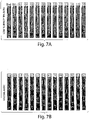
- 238000000879 optical micrograph Methods 0.000 description 4
- 239000008385 outer phase Substances 0.000 description 4
- 239000001301 oxygen Substances 0.000 description 4
- 229910052760 oxygen Inorganic materials 0.000 description 4
- 238000007789 sealing Methods 0.000 description 4
- 238000009736 wetting Methods 0.000 description 4
- QTBSBXVTEAMEQO-UHFFFAOYSA-N Acetic acid Chemical compound CC(O)=O QTBSBXVTEAMEQO-UHFFFAOYSA-N 0.000 description 3
- CSCPPACGZOOCGX-UHFFFAOYSA-N Acetone Chemical compound CC(C)=O CSCPPACGZOOCGX-UHFFFAOYSA-N 0.000 description 3
- 108020004414 DNA Proteins 0.000 description 3
- RTZKZFJDLAIYFH-UHFFFAOYSA-N Diethyl ether Chemical compound CCOCC RTZKZFJDLAIYFH-UHFFFAOYSA-N 0.000 description 3
- LFQSCWFLJHTTHZ-UHFFFAOYSA-N Ethanol Chemical compound CCO LFQSCWFLJHTTHZ-UHFFFAOYSA-N 0.000 description 3
- PEDCQBHIVMGVHV-UHFFFAOYSA-N Glycerine Chemical compound OCC(O)CO PEDCQBHIVMGVHV-UHFFFAOYSA-N 0.000 description 3
- OKKJLVBELUTLKV-UHFFFAOYSA-N Methanol Chemical compound OC OKKJLVBELUTLKV-UHFFFAOYSA-N 0.000 description 3
- 229920002302 Nylon 6,6 Polymers 0.000 description 3
- 239000002202 Polyethylene glycol Substances 0.000 description 3
- DBMJMQXJHONAFJ-UHFFFAOYSA-M Sodium laurylsulphate Chemical compound [Na+].CCCCCCCCCCCCOS([O-])(=O)=O DBMJMQXJHONAFJ-UHFFFAOYSA-M 0.000 description 3
- 229920002125 Sokalan® Polymers 0.000 description 3
- 229910052799 carbon Inorganic materials 0.000 description 3
- 239000003795 chemical substances by application Substances 0.000 description 3
- 238000001816 cooling Methods 0.000 description 3
- 230000003247 decreasing effect Effects 0.000 description 3
- 238000005538 encapsulation Methods 0.000 description 3
- 230000003993 interaction Effects 0.000 description 3
- 238000002844 melting Methods 0.000 description 3
- 230000008018 melting Effects 0.000 description 3
- 238000000465 moulding Methods 0.000 description 3
- VLKZOEOYAKHREP-UHFFFAOYSA-N n-Hexane Chemical compound CCCCCC VLKZOEOYAKHREP-UHFFFAOYSA-N 0.000 description 3
- 230000036961 partial effect Effects 0.000 description 3
- 229920001223 polyethylene glycol Polymers 0.000 description 3
- 229920001296 polysiloxane Polymers 0.000 description 3
- 229920001343 polytetrafluoroethylene Polymers 0.000 description 3
- 239000004810 polytetrafluoroethylene Substances 0.000 description 3
- 102000004169 proteins and genes Human genes 0.000 description 3
- 108090000623 proteins and genes Proteins 0.000 description 3
- 238000010526 radical polymerization reaction Methods 0.000 description 3
- 239000000376 reactant Substances 0.000 description 3
- 230000035882 stress Effects 0.000 description 3
- 239000004094 surface-active agent Substances 0.000 description 3
- SMZOUWXMTYCWNB-UHFFFAOYSA-N 2-(2-methoxy-5-methylphenyl)ethanamine Chemical compound COC1=CC=C(C)C=C1CCN SMZOUWXMTYCWNB-UHFFFAOYSA-N 0.000 description 2
- NIXOWILDQLNWCW-UHFFFAOYSA-N 2-Propenoic acid Natural products OC(=O)C=C NIXOWILDQLNWCW-UHFFFAOYSA-N 0.000 description 2
- HRPVXLWXLXDGHG-UHFFFAOYSA-N Acrylamide Chemical compound NC(=O)C=C HRPVXLWXLXDGHG-UHFFFAOYSA-N 0.000 description 2
- 239000004215 Carbon black (E152) Substances 0.000 description 2
- 102000004190 Enzymes Human genes 0.000 description 2
- 108090000790 Enzymes Proteins 0.000 description 2
- 229920002449 FKM Polymers 0.000 description 2
- 238000005033 Fourier transform infrared spectroscopy Methods 0.000 description 2
- KFZMGEQAYNKOFK-UHFFFAOYSA-N Isopropanol Chemical compound CC(C)O KFZMGEQAYNKOFK-UHFFFAOYSA-N 0.000 description 2
- 239000005062 Polybutadiene Substances 0.000 description 2
- 239000004698 Polyethylene Substances 0.000 description 2
- 239000004793 Polystyrene Substances 0.000 description 2
- 229910052581 Si3N4 Inorganic materials 0.000 description 2
- 239000004809 Teflon Substances 0.000 description 2
- 229920006362 Teflon® Polymers 0.000 description 2
- BOTDANWDWHJENH-UHFFFAOYSA-N Tetraethyl orthosilicate Chemical compound CCO[Si](OCC)(OCC)OCC BOTDANWDWHJENH-UHFFFAOYSA-N 0.000 description 2
- 239000000853 adhesive Substances 0.000 description 2
- 230000001070 adhesive effect Effects 0.000 description 2
- PWAXUOGZOSVGBO-UHFFFAOYSA-N adipoyl chloride Chemical compound ClC(=O)CCCCC(Cl)=O PWAXUOGZOSVGBO-UHFFFAOYSA-N 0.000 description 2
- PNEYBMLMFCGWSK-UHFFFAOYSA-N aluminium oxide Inorganic materials [O-2].[O-2].[O-2].[Al+3].[Al+3] PNEYBMLMFCGWSK-UHFFFAOYSA-N 0.000 description 2
- 238000004458 analytical method Methods 0.000 description 2
- 238000000149 argon plasma sintering Methods 0.000 description 2
- 230000003796 beauty Effects 0.000 description 2
- 230000008901 benefit Effects 0.000 description 2
- 235000013361 beverage Nutrition 0.000 description 2
- IISBACLAFKSPIT-UHFFFAOYSA-N bisphenol A Chemical compound C=1C=C(O)C=CC=1C(C)(C)C1=CC=C(O)C=C1 IISBACLAFKSPIT-UHFFFAOYSA-N 0.000 description 2
- 150000004985 diamines Chemical class 0.000 description 2
- 239000012153 distilled water Substances 0.000 description 2
- 238000005516 engineering process Methods 0.000 description 2
- 238000005530 etching Methods 0.000 description 2
- 235000013305 food Nutrition 0.000 description 2
- 239000003205 fragrance Substances 0.000 description 2
- 230000009477 glass transition Effects 0.000 description 2
- 229910021397 glassy carbon Inorganic materials 0.000 description 2
- 230000036541 health Effects 0.000 description 2
- DCAYPVUWAIABOU-UHFFFAOYSA-N hexadecane Chemical compound CCCCCCCCCCCCCCCC DCAYPVUWAIABOU-UHFFFAOYSA-N 0.000 description 2
- NAQMVNRVTILPCV-UHFFFAOYSA-N hexane-1,6-diamine Chemical compound NCCCCCCN NAQMVNRVTILPCV-UHFFFAOYSA-N 0.000 description 2
- 229930195733 hydrocarbon Natural products 0.000 description 2
- 150000002430 hydrocarbons Chemical class 0.000 description 2
- 239000012528 membrane Substances 0.000 description 2
- 239000003094 microcapsule Substances 0.000 description 2
- 239000003960 organic solvent Substances 0.000 description 2
- 239000007800 oxidant agent Substances 0.000 description 2
- 230000003647 oxidation Effects 0.000 description 2
- 238000007254 oxidation reaction Methods 0.000 description 2
- 230000001590 oxidative effect Effects 0.000 description 2
- 239000003973 paint Substances 0.000 description 2
- 239000008177 pharmaceutical agent Substances 0.000 description 2
- 229920002857 polybutadiene Polymers 0.000 description 2
- 229920000573 polyethylene Polymers 0.000 description 2
- 229920002223 polystyrene Polymers 0.000 description 2
- 239000002243 precursor Substances 0.000 description 2
- 230000002035 prolonged effect Effects 0.000 description 2
- 239000010453 quartz Substances 0.000 description 2
- 125000005372 silanol group Chemical group 0.000 description 2
- HQVNEWCFYHHQES-UHFFFAOYSA-N silicon nitride Chemical compound N12[Si]34N5[Si]62N3[Si]51N64 HQVNEWCFYHHQES-UHFFFAOYSA-N 0.000 description 2
- 229910052814 silicon oxide Inorganic materials 0.000 description 2
- 229920002545 silicone oil Polymers 0.000 description 2
- 229920002379 silicone rubber Polymers 0.000 description 2
- 239000012265 solid product Substances 0.000 description 2
- 238000007711 solidification Methods 0.000 description 2
- 230000008023 solidification Effects 0.000 description 2
- TXEYQDLBPFQVAA-UHFFFAOYSA-N tetrafluoromethane Chemical compound FC(F)(F)F TXEYQDLBPFQVAA-UHFFFAOYSA-N 0.000 description 2
- CPUDPFPXCZDNGI-UHFFFAOYSA-N triethoxy(methyl)silane Chemical compound CCO[Si](C)(OCC)OCC CPUDPFPXCZDNGI-UHFFFAOYSA-N 0.000 description 2
- 108091032973 (ribonucleotides)n+m Proteins 0.000 description 1
- JYEUMXHLPRZUAT-UHFFFAOYSA-N 1,2,3-triazine Chemical compound C1=CN=NN=C1 JYEUMXHLPRZUAT-UHFFFAOYSA-N 0.000 description 1
- SVQLLPOUSBWFHB-UHFFFAOYSA-N 1-(1,2,2,3,3,4,4,5,5,6,6-undecafluorocyclohexyl)ethanol Chemical compound CC(O)C1(F)C(F)(F)C(F)(F)C(F)(F)C(F)(F)C1(F)F SVQLLPOUSBWFHB-UHFFFAOYSA-N 0.000 description 1
- VEXZGXHMUGYJMC-UHFFFAOYSA-M Chloride anion Chemical compound [Cl-] VEXZGXHMUGYJMC-UHFFFAOYSA-M 0.000 description 1
- 239000005046 Chlorosilane Substances 0.000 description 1
- 239000004821 Contact adhesive Substances 0.000 description 1
- IAYPIBMASNFSPL-UHFFFAOYSA-N Ethylene oxide Chemical compound C1CO1 IAYPIBMASNFSPL-UHFFFAOYSA-N 0.000 description 1
- 101000801643 Homo sapiens Retinal-specific phospholipid-transporting ATPase ABCA4 Proteins 0.000 description 1
- 229920001730 Moisture cure polyurethane Polymers 0.000 description 1
- KWYHDKDOAIKMQN-UHFFFAOYSA-N N,N,N',N'-tetramethylethylenediamine Chemical compound CN(C)CCN(C)C KWYHDKDOAIKMQN-UHFFFAOYSA-N 0.000 description 1
- 239000004677 Nylon Substances 0.000 description 1
- 239000004952 Polyamide Substances 0.000 description 1
- 108091030071 RNAI Proteins 0.000 description 1
- 238000001069 Raman spectroscopy Methods 0.000 description 1
- 102100033617 Retinal-specific phospholipid-transporting ATPase ABCA4 Human genes 0.000 description 1
- 108020004459 Small interfering RNA Proteins 0.000 description 1
- FAPWRFPIFSIZLT-UHFFFAOYSA-M Sodium chloride Chemical compound [Na+].[Cl-] FAPWRFPIFSIZLT-UHFFFAOYSA-M 0.000 description 1
- 241000529895 Stercorarius Species 0.000 description 1
- 240000008042 Zea mays Species 0.000 description 1
- 235000005824 Zea mays ssp. parviglumis Nutrition 0.000 description 1
- 235000002017 Zea mays subsp mays Nutrition 0.000 description 1
- CCGWVKHKHWKOIQ-UHFFFAOYSA-N [2-hydroxy-4-(3-triethoxysilylpropoxy)phenyl]-phenylmethanone Chemical compound OC1=CC(OCCC[Si](OCC)(OCC)OCC)=CC=C1C(=O)C1=CC=CC=C1 CCGWVKHKHWKOIQ-UHFFFAOYSA-N 0.000 description 1
- 238000010521 absorption reaction Methods 0.000 description 1
- 150000007513 acids Chemical class 0.000 description 1
- 230000009471 action Effects 0.000 description 1
- 230000002411 adverse Effects 0.000 description 1
- 150000004703 alkoxides Chemical group 0.000 description 1
- 150000001412 amines Chemical group 0.000 description 1
- 238000013459 approach Methods 0.000 description 1
- 150000004982 aromatic amines Chemical class 0.000 description 1
- 230000009286 beneficial effect Effects 0.000 description 1
- 239000003139 biocide Substances 0.000 description 1
- 239000012620 biological material Substances 0.000 description 1
- 230000033228 biological regulation Effects 0.000 description 1
- 239000007853 buffer solution Substances 0.000 description 1
- 125000003636 chemical group Chemical group 0.000 description 1
- 238000001311 chemical methods and process Methods 0.000 description 1
- 238000005229 chemical vapour deposition Methods 0.000 description 1
- VNJCDDZVNHPVNM-UHFFFAOYSA-N chloro(ethyl)silane Chemical class CC[SiH2]Cl VNJCDDZVNHPVNM-UHFFFAOYSA-N 0.000 description 1
- YGZSVWMBUCGDCV-UHFFFAOYSA-N chloro(methyl)silane Chemical class C[SiH2]Cl YGZSVWMBUCGDCV-UHFFFAOYSA-N 0.000 description 1
- NBWIIOQJUKRLKW-UHFFFAOYSA-N chloro(phenyl)silane Chemical class Cl[SiH2]C1=CC=CC=C1 NBWIIOQJUKRLKW-UHFFFAOYSA-N 0.000 description 1
- KOPOQZFJUQMUML-UHFFFAOYSA-N chlorosilane Chemical class Cl[SiH3] KOPOQZFJUQMUML-UHFFFAOYSA-N 0.000 description 1
- 238000002983 circular dichroism Methods 0.000 description 1
- 238000003776 cleavage reaction Methods 0.000 description 1
- 229910052681 coesite Inorganic materials 0.000 description 1
- 230000001427 coherent effect Effects 0.000 description 1
- 239000000470 constituent Substances 0.000 description 1
- 229920001577 copolymer Polymers 0.000 description 1
- 239000007771 core particle Substances 0.000 description 1
- 235000005822 corn Nutrition 0.000 description 1
- 229910052593 corundum Inorganic materials 0.000 description 1
- 229910052906 cristobalite Inorganic materials 0.000 description 1
- 238000004132 cross linking Methods 0.000 description 1
- 150000004292 cyclic ethers Chemical group 0.000 description 1
- 230000003111 delayed effect Effects 0.000 description 1
- 230000001419 dependent effect Effects 0.000 description 1
- 238000005137 deposition process Methods 0.000 description 1
- 238000001514 detection method Methods 0.000 description 1
- 238000010586 diagram Methods 0.000 description 1
- GYZLOYUZLJXAJU-UHFFFAOYSA-N diglycidyl ether Chemical class C1OC1COCC1CO1 GYZLOYUZLJXAJU-UHFFFAOYSA-N 0.000 description 1
- 239000003085 diluting agent Substances 0.000 description 1
- KPUWHANPEXNPJT-UHFFFAOYSA-N disiloxane Chemical class [SiH3]O[SiH3] KPUWHANPEXNPJT-UHFFFAOYSA-N 0.000 description 1
- 238000012377 drug delivery Methods 0.000 description 1
- 238000001035 drying Methods 0.000 description 1
- 239000000975 dye Substances 0.000 description 1
- 229920001971 elastomer Polymers 0.000 description 1
- 239000000806 elastomer Substances 0.000 description 1
- 239000013536 elastomeric material Substances 0.000 description 1
- 238000002848 electrochemical method Methods 0.000 description 1
- 230000005670 electromagnetic radiation Effects 0.000 description 1
- 238000000572 ellipsometry Methods 0.000 description 1
- 125000003700 epoxy group Chemical group 0.000 description 1
- 238000001704 evaporation Methods 0.000 description 1
- 230000008020 evaporation Effects 0.000 description 1
- 230000006355 external stress Effects 0.000 description 1
- 238000011049 filling Methods 0.000 description 1
- 238000001914 filtration Methods 0.000 description 1
- 229910052731 fluorine Inorganic materials 0.000 description 1
- 125000001153 fluoro group Chemical group F* 0.000 description 1
- 229920002313 fluoropolymer Polymers 0.000 description 1
- 239000004811 fluoropolymer Substances 0.000 description 1
- XPBBUZJBQWWFFJ-UHFFFAOYSA-N fluorosilane Chemical compound [SiH3]F XPBBUZJBQWWFFJ-UHFFFAOYSA-N 0.000 description 1
- 239000000417 fungicide Substances 0.000 description 1
- 230000009368 gene silencing by RNA Effects 0.000 description 1
- 235000011187 glycerol Nutrition 0.000 description 1
- 238000010438 heat treatment Methods 0.000 description 1
- 235000012907 honey Nutrition 0.000 description 1
- 229920001477 hydrophilic polymer Polymers 0.000 description 1
- 229920001600 hydrophobic polymer Polymers 0.000 description 1
- 238000003018 immunoassay Methods 0.000 description 1
- 238000000338 in vitro Methods 0.000 description 1
- 238000007373 indentation Methods 0.000 description 1
- 230000001939 inductive effect Effects 0.000 description 1
- 230000000977 initiatory effect Effects 0.000 description 1
- 238000001746 injection moulding Methods 0.000 description 1
- 239000000976 ink Substances 0.000 description 1
- 230000001788 irregular Effects 0.000 description 1
- 239000012948 isocyanate Substances 0.000 description 1
- IQPQWNKOIGAROB-UHFFFAOYSA-N isocyanate group Chemical group [N-]=C=O IQPQWNKOIGAROB-UHFFFAOYSA-N 0.000 description 1
- 238000002955 isolation Methods 0.000 description 1
- 238000002356 laser light scattering Methods 0.000 description 1
- 125000003473 lipid group Chemical group 0.000 description 1
- 239000007791 liquid phase Substances 0.000 description 1
- 230000013011 mating Effects 0.000 description 1
- 239000000155 melt Substances 0.000 description 1
- 230000005499 meniscus Effects 0.000 description 1
- 238000000813 microcontact printing Methods 0.000 description 1
- 238000005459 micromachining Methods 0.000 description 1
- 238000001053 micromoulding Methods 0.000 description 1
- 238000001682 microtransfer moulding Methods 0.000 description 1
- 239000002480 mineral oil Substances 0.000 description 1
- 235000010446 mineral oil Nutrition 0.000 description 1
- 238000002156 mixing Methods 0.000 description 1
- PHQOGHDTIVQXHL-UHFFFAOYSA-N n'-(3-trimethoxysilylpropyl)ethane-1,2-diamine Chemical compound CO[Si](OC)(OC)CCCNCCN PHQOGHDTIVQXHL-UHFFFAOYSA-N 0.000 description 1
- 239000002105 nanoparticle Substances 0.000 description 1
- 229920003986 novolac Polymers 0.000 description 1
- 108020004707 nucleic acids Proteins 0.000 description 1
- 102000039446 nucleic acids Human genes 0.000 description 1
- 150000007523 nucleic acids Chemical class 0.000 description 1
- 238000005935 nucleophilic addition reaction Methods 0.000 description 1
- 229920001778 nylon Polymers 0.000 description 1
- YTJSFYQNRXLOIC-UHFFFAOYSA-N octadecylsilane Chemical compound CCCCCCCCCCCCCCCCCC[SiH3] YTJSFYQNRXLOIC-UHFFFAOYSA-N 0.000 description 1
- SLYCYWCVSGPDFR-UHFFFAOYSA-N octadecyltrimethoxysilane Chemical compound CCCCCCCCCCCCCCCCCC[Si](OC)(OC)OC SLYCYWCVSGPDFR-UHFFFAOYSA-N 0.000 description 1
- TVMXDCGIABBOFY-UHFFFAOYSA-N octane Chemical compound CCCCCCCC TVMXDCGIABBOFY-UHFFFAOYSA-N 0.000 description 1
- 238000000424 optical density measurement Methods 0.000 description 1
- 230000003287 optical effect Effects 0.000 description 1
- 229950011087 perflunafene Drugs 0.000 description 1
- UWEYRJFJVCLAGH-UHFFFAOYSA-N perfluorodecalin Chemical compound FC1(F)C(F)(F)C(F)(F)C(F)(F)C2(F)C(F)(F)C(F)(F)C(F)(F)C(F)(F)C21F UWEYRJFJVCLAGH-UHFFFAOYSA-N 0.000 description 1
- 238000000053 physical method Methods 0.000 description 1
- 238000004987 plasma desorption mass spectroscopy Methods 0.000 description 1
- 238000009832 plasma treatment Methods 0.000 description 1
- 238000000711 polarimetry Methods 0.000 description 1
- 229920000052 poly(p-xylylene) Polymers 0.000 description 1
- 229920002401 polyacrylamide Polymers 0.000 description 1
- 229920000058 polyacrylate Polymers 0.000 description 1
- 239000004584 polyacrylic acid Substances 0.000 description 1
- 229920002647 polyamide Polymers 0.000 description 1
- 239000012704 polymeric precursor Substances 0.000 description 1
- 230000000379 polymerizing effect Effects 0.000 description 1
- 229920001451 polypropylene glycol Polymers 0.000 description 1
- 239000004814 polyurethane Substances 0.000 description 1
- 239000005373 porous glass Substances 0.000 description 1
- 239000003755 preservative agent Substances 0.000 description 1
- 150000003138 primary alcohols Chemical class 0.000 description 1
- 102000004196 processed proteins & peptides Human genes 0.000 description 1
- 108090000765 processed proteins & peptides Proteins 0.000 description 1
- 239000000047 product Substances 0.000 description 1
- 239000002096 quantum dot Substances 0.000 description 1
- 230000005855 radiation Effects 0.000 description 1
- 150000003254 radicals Chemical class 0.000 description 1
- 238000009877 rendering Methods 0.000 description 1
- 238000000820 replica moulding Methods 0.000 description 1
- 238000011160 research Methods 0.000 description 1
- 230000004044 response Effects 0.000 description 1
- 230000002441 reversible effect Effects 0.000 description 1
- 239000012266 salt solution Substances 0.000 description 1
- 150000003839 salts Chemical class 0.000 description 1
- 238000013341 scale-up Methods 0.000 description 1
- 230000007017 scission Effects 0.000 description 1
- 239000010420 shell particle Substances 0.000 description 1
- SCPYDCQAZCOKTP-UHFFFAOYSA-N silanol Chemical compound [SiH3]O SCPYDCQAZCOKTP-UHFFFAOYSA-N 0.000 description 1
- 239000000377 silicon dioxide Substances 0.000 description 1
- 238000002174 soft lithography Methods 0.000 description 1
- 239000011343 solid material Substances 0.000 description 1
- 238000000935 solvent evaporation Methods 0.000 description 1
- 238000004611 spectroscopical analysis Methods 0.000 description 1
- 238000004528 spin coating Methods 0.000 description 1
- 238000009987 spinning Methods 0.000 description 1
- 230000003068 static effect Effects 0.000 description 1
- 229910052682 stishovite Inorganic materials 0.000 description 1
- 239000000725 suspension Substances 0.000 description 1
- 238000003786 synthesis reaction Methods 0.000 description 1
- 239000006188 syrup Substances 0.000 description 1
- 235000020357 syrup Nutrition 0.000 description 1
- 229920001169 thermoplastic Polymers 0.000 description 1
- 229920001187 thermosetting polymer Polymers 0.000 description 1
- 238000013518 transcription Methods 0.000 description 1
- 230000035897 transcription Effects 0.000 description 1
- 238000013519 translation Methods 0.000 description 1
- 239000012780 transparent material Substances 0.000 description 1
- ZDHXKXAHOVTTAH-UHFFFAOYSA-N trichlorosilane Chemical class Cl[SiH](Cl)Cl ZDHXKXAHOVTTAH-UHFFFAOYSA-N 0.000 description 1
- 229910052905 tridymite Inorganic materials 0.000 description 1
- 239000011800 void material Substances 0.000 description 1
- 238000003466 welding Methods 0.000 description 1
- 229910001845 yogo sapphire Inorganic materials 0.000 description 1
Images


Classifications
-
- B—PERFORMING OPERATIONS; TRANSPORTING
- B01—PHYSICAL OR CHEMICAL PROCESSES OR APPARATUS IN GENERAL
- B01F—MIXING, e.g. DISSOLVING, EMULSIFYING OR DISPERSING
- B01F25/00—Flow mixers; Mixers for falling materials, e.g. solid particles
- B01F25/20—Jet mixers, i.e. mixers using high-speed fluid streams
-
- B—PERFORMING OPERATIONS; TRANSPORTING
- B01—PHYSICAL OR CHEMICAL PROCESSES OR APPARATUS IN GENERAL
- B01F—MIXING, e.g. DISSOLVING, EMULSIFYING OR DISPERSING
- B01F23/00—Mixing according to the phases to be mixed, e.g. dispersing or emulsifying
- B01F23/40—Mixing liquids with liquids; Emulsifying
- B01F23/41—Emulsifying
-
- B—PERFORMING OPERATIONS; TRANSPORTING
- B01—PHYSICAL OR CHEMICAL PROCESSES OR APPARATUS IN GENERAL
- B01F—MIXING, e.g. DISSOLVING, EMULSIFYING OR DISPERSING
- B01F25/00—Flow mixers; Mixers for falling materials, e.g. solid particles
- B01F25/80—Falling particle mixers, e.g. with repeated agitation along a vertical axis
- B01F25/90—Falling particle mixers, e.g. with repeated agitation along a vertical axis with moving or vibrating means, e.g. stirrers, for enhancing the mixing
-
- B—PERFORMING OPERATIONS; TRANSPORTING
- B01—PHYSICAL OR CHEMICAL PROCESSES OR APPARATUS IN GENERAL
- B01F—MIXING, e.g. DISSOLVING, EMULSIFYING OR DISPERSING
- B01F33/00—Other mixers; Mixing plants; Combinations of mixers
- B01F33/30—Micromixers
- B01F33/301—Micromixers using specific means for arranging the streams to be mixed, e.g. channel geometries or dispositions
- B01F33/3011—Micromixers using specific means for arranging the streams to be mixed, e.g. channel geometries or dispositions using a sheathing stream of a fluid surrounding a central stream of a different fluid, e.g. for reducing the cross-section of the central stream or to produce droplets from the central stream
-
- B—PERFORMING OPERATIONS; TRANSPORTING
- B01—PHYSICAL OR CHEMICAL PROCESSES OR APPARATUS IN GENERAL
- B01F—MIXING, e.g. DISSOLVING, EMULSIFYING OR DISPERSING
- B01F33/00—Other mixers; Mixing plants; Combinations of mixers
- B01F33/30—Micromixers
- B01F33/3035—Micromixers using surface tension to mix, move or hold the fluids
- B01F33/30351—Micromixers using surface tension to mix, move or hold the fluids using hydrophilic/hydrophobic surfaces
-
- B—PERFORMING OPERATIONS; TRANSPORTING
- B01—PHYSICAL OR CHEMICAL PROCESSES OR APPARATUS IN GENERAL
- B01F—MIXING, e.g. DISSOLVING, EMULSIFYING OR DISPERSING
- B01F35/00—Accessories for mixers; Auxiliary operations or auxiliary devices; Parts or details of general application
- B01F35/80—Forming a predetermined ratio of the substances to be mixed
-
- F—MECHANICAL ENGINEERING; LIGHTING; HEATING; WEAPONS; BLASTING
- F17—STORING OR DISTRIBUTING GASES OR LIQUIDS
- F17D—PIPE-LINE SYSTEMS; PIPE-LINES
- F17D1/00—Pipe-line systems
-
- B—PERFORMING OPERATIONS; TRANSPORTING
- B01—PHYSICAL OR CHEMICAL PROCESSES OR APPARATUS IN GENERAL
- B01F—MIXING, e.g. DISSOLVING, EMULSIFYING OR DISPERSING
- B01F2215/00—Auxiliary or complementary information in relation with mixing
- B01F2215/04—Technical information in relation with mixing
- B01F2215/0413—Numerical information
- B01F2215/0418—Geometrical information
- B01F2215/0431—Numerical size values, e.g. diameter of a hole or conduit, area, volume, length, width, or ratios thereof
-
- B—PERFORMING OPERATIONS; TRANSPORTING
- B01—PHYSICAL OR CHEMICAL PROCESSES OR APPARATUS IN GENERAL
- B01F—MIXING, e.g. DISSOLVING, EMULSIFYING OR DISPERSING
- B01F2215/00—Auxiliary or complementary information in relation with mixing
- B01F2215/04—Technical information in relation with mixing
- B01F2215/0413—Numerical information
- B01F2215/0436—Operational information
- B01F2215/045—Numerical flow-rate values
-
- B—PERFORMING OPERATIONS; TRANSPORTING
- B01—PHYSICAL OR CHEMICAL PROCESSES OR APPARATUS IN GENERAL
- B01F—MIXING, e.g. DISSOLVING, EMULSIFYING OR DISPERSING
- B01F2215/00—Auxiliary or complementary information in relation with mixing
- B01F2215/04—Technical information in relation with mixing
- B01F2215/0413—Numerical information
- B01F2215/0436—Operational information
- B01F2215/0459—Numerical values of dimensionless numbers, i.e. Re, Pr, Nu, transfer coefficients
-
- B—PERFORMING OPERATIONS; TRANSPORTING
- B01—PHYSICAL OR CHEMICAL PROCESSES OR APPARATUS IN GENERAL
- B01F—MIXING, e.g. DISSOLVING, EMULSIFYING OR DISPERSING
- B01F23/00—Mixing according to the phases to be mixed, e.g. dispersing or emulsifying
- B01F23/40—Mixing liquids with liquids; Emulsifying
- B01F23/41—Emulsifying
- B01F23/414—Emulsifying characterised by the internal structure of the emulsion
- B01F23/4144—Multiple emulsions, in particular double emulsions, e.g. water in oil in water; Three-phase emulsions
-
- Y—GENERAL TAGGING OF NEW TECHNOLOGICAL DEVELOPMENTS; GENERAL TAGGING OF CROSS-SECTIONAL TECHNOLOGIES SPANNING OVER SEVERAL SECTIONS OF THE IPC; TECHNICAL SUBJECTS COVERED BY FORMER USPC CROSS-REFERENCE ART COLLECTIONS [XRACs] AND DIGESTS
- Y10—TECHNICAL SUBJECTS COVERED BY FORMER USPC
- Y10T—TECHNICAL SUBJECTS COVERED BY FORMER US CLASSIFICATION
- Y10T137/00—Fluid handling
- Y10T137/0318—Processes
-
- Y—GENERAL TAGGING OF NEW TECHNOLOGICAL DEVELOPMENTS; GENERAL TAGGING OF CROSS-SECTIONAL TECHNOLOGIES SPANNING OVER SEVERAL SECTIONS OF THE IPC; TECHNICAL SUBJECTS COVERED BY FORMER USPC CROSS-REFERENCE ART COLLECTIONS [XRACs] AND DIGESTS
- Y10—TECHNICAL SUBJECTS COVERED BY FORMER USPC
- Y10T—TECHNICAL SUBJECTS COVERED BY FORMER US CLASSIFICATION
- Y10T137/00—Fluid handling
- Y10T137/8593—Systems
- Y10T137/85938—Non-valved flow dividers
Definitions
- the present invention generally relates to emulsions, and more particularly, to multiple emulsions.
- An emulsion is a fluidic state which exists when a first fluid is dispersed in a second fluid that is typically immiscible with the first fluid.
- Examples of common emulsions are oil in water and water in oil emulsions.
- Multiple emulsions are emulsions that are formed with more than two fluids, or two or more fluids arranged in a more complex manner than a typical two-fluid emulsion.
- a multiple emulsion may be oil-in-water-in-oil ("o/w/o"), or water-in-oil-in-water (“w/o/w").
- o/w/o oil-in-water-in-oil
- w/o/w water-in-oil-in-water
- multiple emulsions of a droplet inside another droplet are made using a two-stage emulsification technique, such as by applying shear forces or emulsification through mixing to reduce the size of droplets formed during the emulsification process.
- Other methods such as membrane emulsification techniques using, for example, a porous glass membrane, have also been used to produce water-in-oil-in-water emulsions.
- Microfluidic techniques have also been used to produce droplets inside of droplets using a procedure including two or more steps. For example, see International Patent Application No. PCT/US2004/010903, filed April 9, 2004, entitled "Formation and Control of Fluidic Species," by Link, et al.
- WO 2005/103106 A1 discloses a method and apparatus for producing polymeric particles with pre-designed size, shape, morphology and composition
- the method includes injecting a first fluid comprising a polymerizable constituent with a controlled flow rate into a microfluidic channel and injecting a second fluid with a controlled flow rate into the microfluidic channel in which the second fluid mixes with the first fluid, the second fluid being immiscible with the first fluid so that the first fluid forms into droplets in the microfluidic channel.
- the microfluidic channel has pre-selected dimensions to give droplets of pre-selected size, morphology and shape.
- EP 1 757 357 A1 discloses a method and a device for producing microdroplets.
- the apparatus has a cross intersection portion at which a first continuous phase, a first dispersion phase, and a second dispersion phase intersect with each other, a first liquid feed device controlling the first dispersion phase, a second liquid feed device controlling the second dispersion phase, and a control device connected to the first liquid feed device and the second liquid feed device, in which the first liquid feed device and the second liquid feed device are controlled by a signal from the control device so that microdroplets formed of the first dispersion phase and microdroplets formed of the second dispersion phase are sequentially produced.
- hydrodynamic phenomena e.g., multiphase laminar flow
- the present invention generally relates to emulsions, and more particularly, to multiple emulsions.
- the subject matter of the present invention involves, in some cases, interrelated products, alternative solutions to a particular problem, and/or a plurality of different uses of one or more systems and/or articles.
- the invention is directed to an apparatus.
- the apparatus includes a main microfluidic channel, at least one first side microfluidic channel intersecting the main microfluidic channel at a first intersection, and at least one second side microfluidic channel intersecting the main microfluidic channel at a second intersection distinct from the first intersection.
- the second intersection separates the main microfluidic channel into a first portion on a first side and a second portion on an opposing side of the second intersection, where the first portion is defined on the side of the main microfluidic channel between the first intersection and the second intersection.
- the second portion of the main microfluidic channel has an average cross-sectional dimension between about 5% and about 20% larger than an average cross-sectional dimension of the first portion of the main microfluidic channel, relative to the average cross-sectional dimension of the first portion of the main microfluidic channel, wherein the average cross-sectional dimension of the first portion and the average cross-sectional dimension of the second portion result in a Weber number of less than 1 in the first portion and a Weber number greater than 1 in the second portion.
- the first portion of the main microfluidic channel has a first hydrophilicity and the second portion of the main microfluidic channel has a second hydrophilicity different than the first hydrophilicity.
- the invention in another aspect, is directed to a method.
- the method includes acts of providing a first, inner fluid in a main microfluidic channel, flowing the first, inner fluid to a first intersection of the main microfluidic channel and a first side microfluidic channel containing a second, outer fluid to cause the first, inner fluid to become surrounded by the second, outer fluid without causing the first, inner fluid to form separate droplets prior to contact with a third, carrying fluid, wherein the first, inner fluid is immiscible with the second, outer fluid and the second, outer fluid is immiscible with the third, carrying fluid, flowing the first, inner fluid and the second, outer fluid to a second intersection of the main microfluidic channel and a second side microfluidic channel containing the third, carrying fluid to cause the second, outer fluid to become surrounded by the third, carrying fluid without causing the first, inner fluid and the second, outer fluid to form separate droplets, wherein the main microfluidic channel downstream of the second intersection has an average
- the method includes acts of creating a multiple emulsion droplet in a third, carrying fluid within a quasi-two dimensional microfluidic channel.
- the multiple emulsion may include at least a third, carrying fluid and a first, inner fluid surrounded by and in physical contact with the third, carrying fluid.
- an average distance of separation between a first interface between the third, carrying fluid and the first, inner fluid, and a second interface between the first, inner fluid and a second, outer fluid is no more than about 1 micrometer.
- an average distance of separation between a first interface between the third, carrying fluid and the first, inner fluid, and a second interface between the first, inner fluid and the second, outer fluid is no more than about 10% of the average dimension of the droplet.
- the multiple emulsion may also contain other fluids or nestings of fluids, other species, etc.
- the present invention is directed to an article including a first, inner fluidic droplet surrounded by a second fluidic droplet, the second fluidic droplet surrounded by a third, carrying fluid.
- the first fluidic droplet comprises a fluid that has a surface tension in air at 25 °C of no more than about 40 mN/m.
- the first, inner fluid has a first surface tension in air at 25 °C and the second, outer fluid has a second surface tension in air 25 °C, where the second surface tension is at least 2 times the first surface tension.
- the first, inner fluid has a viscosity at 25 °C of at least 20 mPa s.
- the article includes a second, outer fluid comprising discrete droplets of a first, inner fluid, at least about 90% of the discrete droplets of the first, inner fluid having a distribution of diameters such that no more than about 10% of the discrete droplets have a dimension greater than about 10% of the average dimension of the discrete droplets.
- the first fluidic droplet comprises a fluid that has a surface tension in air at 25 °C of no more than about 40 mN/m.
- the first, inner fluid has a first surface tension in air at 25 °C and the second, outer fluid has a second surface tension in air 25 °C, where the second surface tension is at least 2 times the first surface tension.
- the first, inner fluid has a viscosity at 25 °C of at least 20 mPa s.
- Still another not claimed aspect of the invention is directed to a method of making a multiple emulsion, including an act of forming a first droplet from a first, inner fluid surrounded by a second, outer fluid while the second, outer fluid is surrounded by a third, carrying fluid.
- the first fluidic droplet comprises a fluid that has a surface tension in air at 25 °C of no more than about 40 mN/m.
- the first, inner fluid has a first surface tension in air at 25 °C and the second, outer fluid has a second surface tension in air 25 °C, where the second surface tension is at least 2 times the first surface tension.
- the first, inner fluid has a viscosity at 25 °C of at least 20 mPa s.
- the present invention is directed to a method of making one or more of the embodiments described herein, for example, a multiple emulsion. In another not claimed aspect, the present invention is directed to a method of using one or more of the embodiments described herein, for example, a multiple emulsion.
- the present invention generally relates to emulsions, and more particularly, to multiple emulsions.
- multiple emulsions are formed by urging a fluid into a channel, e.g., by causing the fluid to enter the channel as a "jet.”
- Side channels can be used to encapsulate the fluid with a surrounding fluid.
- multiple fluids may flow through a channel collinearly before multiple emulsion droplets are formed.
- the fluidic channels may also, in certain embodiments, include varying degrees of hydrophilicity or hydrophobicity.
- the fluidic channel may be relatively hydrophilic upstream of an intersection (or other region within the channel) and relatively hydrophobic downstream of the intersection, or vice versa.
- the average cross-sectional dimension may change, e.g., at an intersection.
- the average cross-sectional dimension may increase at the intersection.
- a relatively small increase in dimension, in combination with a change in hydrophilicity of the fluidic channel may delay droplet formation of a stream of collinearly-flowing multiple fluids under certain flow conditions; accordingly, the point at which multiple emulsion droplets are formed can be readily controlled within the fluidic channel.
- the multiple droplet may be formed from the collinear flow of fluids at (or near) a single location within the fluidic channel.
- systems such as those described herein may be used to encapsulate fluids in single or multiple emulsions that are difficult or impossible to encapsulate using other techniques, such as fluids with low surface tension, viscous fluids, or viscoelastic fluids.
- Other aspects of the invention are generally directed to methods of making and using such systems, kits involving such systems, emulsions created using such systems, or the like.
- the present invention generally relates to emulsions, including multiple emulsions, and to methods and apparatuses for making such emulsions.
- a "multiple emulsion,” as used herein, describes larger droplets that contain one or more smaller droplets therein.
- the larger droplets may, in turn, be contained within another fluid, which may be the same or different than the fluid within the smaller droplet.
- larger degrees of nesting within the multiple emulsion are possible.
- an emulsion may contain droplets containing smaller droplets therein, where at least some of the smaller droplets contain even smaller droplets therein, etc.
- emulsions can be useful for encapsulating species such as pharmaceutical agents, cells, chemicals, or the like. As described below, multiple emulsions can be formed in certain embodiments with generally precise repeatability. In some cases, the encapsulation of the agent may be performed relatively quantitatively, as discussed below.
- Fields in which emulsions or multiple emulsions may prove useful include, for example, food, beverage, health and beauty aids, paints and coatings, and drugs and drug delivery.
- a precise quantity of a drug, pharmaceutical, or other agent can be contained within an emulsion, or in some instances, cells can be contained within a droplet, and the cells can be stored and/or delivered.
- Other species that can be stored and/or delivered include, for example, biochemical species such as nucleic acids such as siRNA, RNAi and DNA, proteins, peptides, or enzymes, or the like.
- Additional species that can be incorporated within an emulsion of the invention include, but are not limited to, nanoparticles, quantum dots, fragrances, proteins, indicators, dyes, fluorescent species, chemicals, drugs, or the like.
- An emulsion can also serve as a reaction vessel in certain cases, such as for controlling chemical reactions, or for in vitro transcription and translation, e.g., for directed evolution technology.
- an emulsion having a consistent size and/or number of droplets can be produced, and/or a consistent ratio of size and/or number of outer droplets to inner droplets (or other such ratios) can be produced for cases involving multiple emulsions.
- a single droplet within an outer droplet of predictable size can be used to provide a specific quantity of a drug.
- combinations of compounds or drugs may be stored, transported, or delivered in a droplet.
- hydrophobic and hydrophilic species can be delivered in a single, multiple emulsion droplet, as the droplet can include both hydrophilic and hydrophobic portions. The amount and concentration of each of these portions can be consistently controlled according to certain embodiments of the invention, which can provide for a predictable and consistent ratio of two or more species in a multiple emulsion droplet.
- the present invention is generally directed to methods of creating multiple emulsions, including double emulsions, triple emulsions, and other higher-order emulsions.
- a fluid flows through a channel, and is surrounded by another fluid.
- the two fluids may flow in a collinear fashion, e.g., without creating individual droplets.
- the two fluids may then be surrounded by yet another fluid, which may flow collinearly with the first two fluids in some embodiments, and/or cause the fluids to form discrete droplets within the channel.
- streams of multiple collinear fluids may be formed, and/or caused to form triple or higher-order emulsions. In some cases, as discussed below, this may occur as a single process, e.g., the multiple emulsion is formed at substantially the same time from the various streams of collinear fluids.
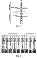
- system 10 includes a main channel 15, which can be a microfluidic channel. Intersecting main channel 15 are a plurality of side channels.
- Main channel 15 in Fig. 1A is shown as being substantially straight; however, in other embodiments, the main channel may be curved, angled, bent, or have other shapes.
- Fig. 1A two sets of channels are shown intersecting main channel 15: a first set of channels 20 that intersects main channel 15 to define intersection 25, and a second set of channels 30 that intersects main channel 15 to define intersection 35.
- larger numbers of intersections may be used to create higher-order multiple emulsions (e.g., having first, second, and third intersections to create triple emulsions, four intersections to create quadruple emulsions, etc.), and/or different numbers of side channels may intersect the main channel.
- an intersection may be defined by one side channel, 3 side channels, 4 side channels, 5 side channels, etc.
- each side channel intersects the main channel at substantially right angles; however, in other embodiments, the side channels need not intersect the main channel at substantially right angles.
- the number of side channels need not be the same between different intersections. For instance, a first intersection may be defined by two side channels intersecting the main channel, while a second intersection may be defined by 1 or 3 side channels intersecting the main channel, etc.
- the main channel may contain a first portion and a second portion distinct from the first portion.
- the first portion and second portion can each be defined as being on different sides of one of the intersections of the main channel with one of the side channels, or the first portion and the second portions may be defined at separate points within the main channel (i.e., not necessarily defined by an intersection).
- first channel 15 includes a first portion 11 and a second portion 12, defined on different sides of the main channel around intersection 35.
- One or more portions may contain other intersections therein, e.g., intersection 25 for first portion 11 in Fig. 1A .
- the first portion and the second portion may have different average cross-sectional dimension, where the "average cross-sectional dimension" is defined perpendicular to fluid flow within the channel.
- the average cross-sectional dimensions of each portion may be determined in a region immediately adjacent to the intersection defining the first and second portions of the main channel.
- the average cross-sectional dimension of a microfluidic channel may be the diameter of a perfect circle having an area equal to the area of the cross-section of the microfluidic channel.
- the first portion may be smaller than the second portion.
- the second portion may have an average cross-sectional dimension that is at least about 5% larger than an average cross-sectional dimension of the first portion of the main fluidic channel, and in some cases, at least about 10%, at least about 15%, at least about 20%, at least about 25%, etc. The percentages can be determined relative to the average cross-sectional dimension of the first portion of the main fluidic channel.
- the second portion has an average cross-sectional dimension that is between about 5% and about 20%, between about 10% and about 20%, or between about 5% and about 10% larger than an average cross-sectional dimension of the first portion of the main fluidic channel.
- the first portion is smaller than the second portion, e.g., at least about 5% smaller than an average cross-sectional dimension of the first portion of the main fluidic channel, and in some cases, at least about 10%, at least about 15%, at least about 20%, at least about 25%, etc., or the second portion may have an average cross-sectional dimension that is between about 5% and about 20%, between about 10% and about 20%, or between about 5% and about 10% smaller than an average cross-sectional dimension of the first portion of the main fluidic channel.
- the difference in cross-sectional dimension of the first portion and the second portion may be a difference in one dimension (e.g., the portions may have the same height and different widths or vice versa) or in some cases, the difference may be in two dimensions (e.g., the portions differ in both height and width).
- using a larger second portion, relative to the first portion may facilitate the collinear flow of multiple streams of fluid in the main channel without causing one of the fluids to break up to create individual droplets. It is believed that this can occur as the increase in average cross-sectional dimension may facilitate increased flow of fluid and/or prevent the inner fluids from contacting the sides of the fluidic channel.
- fluid entering the channel may be directed at a first speed such that the fluid does not break into individual droplets (e.g., under "jetting" behavior), then the fluid may be slowed down, for instance, by increasing the average cross-sectional dimension of the channel such that the fluid is able to break into individual droplets.
- such fluid behavior can be determined using "Weber numbers" (We), where the Weber number can be thought of as the balance or ratio between inertial effects (which keeps the fluid coherent) and surface tension effects (which causes the fluid to tend to form droplets).
- the Weber number is often expressed as a dimensionless ratio of surface tension effects divided by inertial effects, i.e., when the Weber number is greater than 1, surface tension effects dominate, and when the Weber number is less than 1, inertial effects dominate.
- the point at which the fluid within the channel breaks into individual droplets can be controlled, i.e., by controlling the point at which surface tension effects begin to dominate over inertial effects.
- the Weber number can be controlled, for instance, by controlling the speed of fluid within the channel and/or the shape or size of the channel, e.g., its average cross-sectional dimension.
- the average cross-sectional dimension of the channel can be controlled such that a first portion of the channel exhibits a Weber number of less than 1 while a second portion of the channel exhibits a Weber number greater than 1.
- the fluid may be drawn through the channel using any suitable technique, e.g., using positive or negative (vacuum) pressures (i.e., pressures less than atmospheric or ambient pressure).
- positive or negative (vacuum) pressures i.e., pressures less than atmospheric or ambient pressure.
- the hydrophilicities of the first and second portions may be different. In other embodiments, however, the hydrophilicities of the first and second portions may be the same. Hydrophilicities may be determined, for example, using water contact angle measurements or the like. For instance, the first portion may have a first hydrophilicity and the second portion may have a second hydrophilicity substantially different than the first hydrophilicity, for example, being more hydrophilic or more hydrophobic.
- the hydrophilicities of the portions may be controlled, for example, as discussed below. Other suitable techniques for controlling hydrophilicity may be found in International Patent Application No.
- PCT/US2009/000850 filed February 11, 2009, entitled “Surfaces, Including Microfluidic Channels, with Controlled Wetting Properties,” by Abate, et al. , published as WO 2009/120254 on October 1, 2009 ; and International Patent Application No. PCT/US2008/009477, filed August 7, 2008, entitled “Metal Oxide Coating on Surfaces,” by Weitz, et al. , published as WO 2009/020633 on February 12, 2009 .
- different portions of a channel may have different hydrophilicities, e.g., as is discussed in U.S. Provisional Patent pplication Serial No.
- the "difficult" fluid may be used as an inner fluid (first fluid), while a different fluid, such as water may be used as a surrounding or outer fluid (second fluid).
- the outer fluid may be one that readily forms droplets or emulsifies, such as water, or other fluids as disclosed herein. While the inner fluid may not readily emulsify to form droplets in isolation, the action of the outer fluid in forming droplets, e.g., as discussed herein, also causes the inner fluid to form droplets, thereby producing a multiple emulsion in which a droplet of the inner fluid is surrounded by a droplet of the outer fluid, which in turn is contained within a carrying fluid (third fluid).
- This process may be repeated, e.g., to create higher-level multiple emulsions, or the carrying fluid may be removed (e.g., by filtration) such that the outer fluid is able to condense into a continuous fluid, thereby forming a single emulsion of droplets of the inner fluid in a continuous outer fluid.
- the droplet formation process may also be controlled to produce monodisperse droplets of substantially the same shape and/or size. Accordingly, in various embodiments of the present invention, emulsions may be created that contain fluids that are difficult to emulsify under other conditions, such as fluids having low surface tension, having high viscosity, or exhibiting viscoelastic properties.
- fluids having low surface tension do not readily emulsify, since such fluids do not readily dissociate into individual droplets, instead preferring to form continuous fluids or jets.
- the surface tension of a fluid can be thought of as a measure of the tendency of the fluid to prefer to bind to itself rather than to another fluid, so that fluids having high surface tension tend to form spherical shapes or individual droplets in order to minimize the exposed surface area per volume.
- fluids having low surface tension do not typically exhibit this property (or exhibit it poorly), and are generally unsuitable for emulsification as a result.
- an emulsion or a multiple emulsion can be formed using a fluid having low surface tension.
- the surface tension of the fluid (typically measured at 25 °C and 1 atm relative to air) may be no more than about 40 mN/m, no more than about 35 mN/m, no more than about 30 mN/m, no more than about 25 mN/m, no more than about 20 mN/m, or no more than about 15 mN/m.
- the surface tension of a fluid can be determined using any suitable technique known to those of ordinary skill in the art, for example, the Du Nouy Ring method, the Wilhelmy plate method, the spinning drop method, the pendant drop method, the bubble pressure method (or Jaeger's method), the drop volume method, the capillary rise method, the stalagmometric method, or the sessile drop method.
- fluids having low surface tension include non-polar and/or organic fluids such as octanol, diethyl ether, hexane, isopropanol, octane, ethanol, methanol, acetone, acetic acid, or the like.
- the surface tension may be measured relative to the surface tension of a surrounding fluid.
- an inner fluid having low surface tension may be surrounded by an outer fluid having a surface tension that is at least about 2, at least about 2.5, at least about 3, at least about 4, at least about 5, at least about 7, at least about 10, etc. times greater than the surface tension of the inner fluid.
- the inner fluid may be one that has relatively high viscosity.
- High viscosity fluids are ones that do not flow quickly or readily, and hence do not quickly form droplets.
- the viscosity of the fluid may be at least about 15 mPa s, at least about 20 mPa s, at least about 30 mPa s, at least about 100 mPa s, at least about 300 mPa s, at least about 1,000 mPa s, at least about 3,000 mPa s, at least about 10 4 mPa s, etc.
- the viscosity of a fluid is determined at 25 °C, using techniques known to those of ordinary skill in the art, such as viscometers, e.g., U-tube viscometers, falling sphere viscometers, falling piston viscometers, oscillating piston viscometers, vibrational viscometers, rotational viscometers, bubble viscometers, etc.
- viscometers e.g., U-tube viscometers, falling sphere viscometers, falling piston viscometers, oscillating piston viscometers, vibrational viscometers, rotational viscometers, bubble viscometers, etc.
- fluids having relatively high viscosities include, but are not limited to, corn syrup, glycerol, honey, polymeric solutions (e.g., polyurethane (PU) / polybutadiene (PBD) copolymer, polyethylene glycol, polypropylene glycol, etc.), or the like.
- PU polyurethane
- a fluid having high viscosity also exhibits elastic properties more typical of a solid, i.e., the fluid is viscoelastic.
- Elasticity may be thought of as the tendency of a material to try to return to its original shape when subjected to an external stress (in contrast, a pure fluid has no tendency or ability to return to its original shape once stress is applied, independent of the container containing the fluid); such fluids typically cannot be emulsified because of this tendency, rather than forming droplets.
- elasticity is measured by determining Young's modulus, usually at 25 °C.
- a fluid may have a Young's modulus of at least about 0.01 GPa, at least about 0.03 GPa, at least about 0.1 GPa, at least about 0.3 GPa, at least about 1 GPa, at least about 3 GPa, or at least about 10 GPa. Young's modulus can be measured using any suitable technique known to those of ordinary skill in the art, for example, by determining the stress-strain relationship for such fluids.
- the droplets formed as discussed herein may be of substantially the same shape and/or size (i.e., "monodisperse”), or of different shapes and/or sizes, depending on the particular application.
- the term "fluid” generally refers to a substance that tends to flow and to conform to the outline of its container, i.e., a liquid, a gas, a viscoelastic fluid, etc.
- fluids are materials that are unable to withstand a static shear stress, and when a shear stress is applied, the fluid experiences a continuing and permanent distortion.
- the fluid may have any suitable viscosity that permits flow.
- each fluid may be independently selected among essentially any fluids (liquids, gases, and the like) by those of ordinary skill in the art, by considering the relationship between the fluids.
- the droplets may be contained within a carrier fluid, e.g., a liquid. It should be noted, however, that the present invention is not limited to only multiple emulsions. In some embodiments, single emulsions can also be produced.
- a “droplet,” as used herein, is an isolated portion of a first, inner fluid that is surrounded by a second, outer fluid. It is to be noted that a droplet is not necessarily spherical, but may assume other shapes as well, for example, depending on the external environment. In one embodiment, the droplet has a minimum cross-sectional dimension that is substantially equal to the largest dimension of the channel perpendicular to fluid flow in which the droplet is located.
- the droplets will have a homogenous distribution of diameters, i.e., the droplets may have a distribution of diameters such that no more than about 10%, about 5%, about 3%, about 1%, about 0.03%, or about 0.01% of the droplets have an average diameter greater than about 10%, about 5%, about 3%, about 1%, about 0.03%, or about 0.01% of the average diameter of the droplets, and correspondingly, droplets within the outlet channel may have the same, or similar, distribution of diameters.
- Techniques for producing such a homogenous distribution of diameters are also disclosed in International Patent Application No.
- an first, inner fluid flows through the main channel, while a second, outer fluid flows into a first intersection through one or more side channels, and a third, carrying fluid flows into a second intersection through one or more side channels.
- the second, outer fluid upon entry into the main channel, may surround the first, inner fluid without causing the first, inner fluid to form separate droplets.
- the first, inner fluid and the second, outer fluid may flow collinearly within the main channel.
- the second, outer fluid in some cases, may surround the first, inner fluid, preventing the first, inner fluid from contacting the walls of the fluidic channel; for instance, the channel may widen upon entry of the outer fluid in some embodiments.
- additional channels may bring additional fluids to the main channel without causing droplet formation to occur.
- a third, carrying fluid may be introduced into the main channel, surrounding the first, inner fluid and the second, outer fluid.
- introduction of the third, carrying fluid may cause the fluids to form into separate droplets (e.g., of an first, inner fluid, surrounded by a second, outer fluid, which is in turn surrounded by a third, carrying fluid); in other cases, however, droplet formation may be delayed, e.g., by controlling the Weber number of the third, carrying fluid, as previously discussed.
- the third, carrying fluid may prevent the first, inner fluid and/or the second, outer fluid from contacting the walls of fluidic channel; for instance, the channel may widen upon entry of the third, carrying fluid, or in some cases, third, carrying fluid may be added using more than one side channel and/or at more than one intersection.
- more than three fluids may be present.
- some or all of these fluids may exhibit jetting behavior, e.g., the fluids may be allowed to jet without being broken into individual droplets.
- multiple collinear streams of fluid may be formed within a microfluidic channel, and in some cases, one or more of the streams of fluid may exhibit jetting behavior.
- one embodiment of the invention is generally directed to the formation of two, three, four, or more collinear fluids within a microfluidic channel, some or all of which exhibit jetting behavior.
- some or all of these fluids may be hardened, e.g., to produce hardened streams or threads.
- the collinearly flowing fluids may be caused to form a multiple emulsion droplet, as discussed herein.
- the multiple emulsion droplet may be formed in a single step, e.g., without creating single or double emulsion droplets prior to creating the multiple emulsion droplet.
- system 10 includes a main channel 15, which can be a microfluidic channel, with intersections 25, 35, and 45, each formed by the intersection of various side channels (first channels 20, second channels 30, and third channels 40) with main channel 15.
- intersection 35 is used to define a first portion 11 of the main channel and a second portion 12, although in other embodiments, the first and second portions may be defined in other ways, e.g., at another intersection or location within the main channel.
- second portion 12 has an average cross-sectional dimension that is greater than the average cross-sectional dimension of the first portion.
- first portion and the second portion may also exhibit different hydrophilicities as well.
- first portion 11 may be relatively hydrophilic
- second portion 12 may be relatively hydrophobic
- the various hydrophilicities may be controlled, for example, using sol-gel coatings such as those discussed herein.
- a first, inner fluid may be delivered to system 10 through main channel 15, while a second, outer fluid can be delivered through side channels 20, meeting main channel 15 at intersection 25.
- the first, inner fluid and the second, outer fluid in some embodiments, may flow collinearly without the formation of droplets in main channel 25 between intersections 25 and 35.
- a second, outer fluid may be delivered via side channels 30.
- the third, carrying fluid may surround the first, inner fluid and the second, outer fluid, in some cases causing the first, inner fluid and the second, outer fluid to form multiple emulsion droplets (where the second, outer fluid surrounds the first, inner fluid), but in other cases, the various fluids may flow collinearly without the formation of droplets.
- channels 40 may also contain a third, carrying fluid, and the introduction of an additional third, carrying fluid may cause the formation of separate droplets to occur.
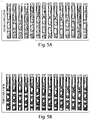
- a non-limiting example of this process is illustrated in Figs. 2 and 3 for an oil/water/oil multiple emulsion droplet.
- channel 15 may contain a first, inner fluid, channel 20 a second, outer fluid, channel 30 a third, carrying fluid, and channel 40 a third, carrying fluid to create a quadruple emulsion droplet of the first, inner fluid, surrounded by the second, outer fluid, surrounded by the third, carrying fluid, which is contained within the third, carrying fluid.
- double or multiple emulsions containing relatively thin layers of fluid may be formed, e.g., using techniques such as those discussed herein.
- one or more fluids may be hardened. Similar techniques may be used to harden streams or jets of fluids (i.e., without necessarily forming droplets or emulsions).
- collinear streams of fluid may be hardened to form threads, including nested threads comprising several nested layers, using fluid hardening techniques such as those described below.
- relatively thin layers of fluid may be formed by controlling the flow rates of the various fluids forming the multiple emulsion and/or controlling the Weber number such that the multiple emulsion droplet that is formed has a relatively large amount of one fluid (e.g., the innermost fluid), compared to other fluids.
- very thin "shells" of fluid may be formed surrounding a droplet, unlike in other techniques in which the thickness of the fluid is inherently limited.
- a fluid "shell" surrounding a droplet may be defined as being between two interfaces, a first interface between a first, inner fluid and a third, carrying fluid, and a second interface between the first, inner fluid and a second, outer fluid.
- the interfaces may have an average distance of separation (determined as an average over the droplet) that is no more than about 1 mm, about 300 micrometers, about 100 micrometers, about 30 micrometers, about 10 micrometers, about 3 micrometers, about 1 micrometers, etc. In some cases, the interfaces may have an average distance of separation defined relative to the average dimension of the droplet.
- the average distance of separation may be less than about 30%, less than about 25%, less than about 20%, less than about 15%, less than about 10%, less than about 5%, less than about 3%, less than about 2%, or less than about 1% of the average dimension of the droplet.
- fluid hardening techniques useful for forming hardened droplets and/or hardened streams of fluid include those discussed in detail below, as well as those disclosed in International Patent Application No. PCT/US2004/010903, filed April 9, 2004, entitled “Formation and Control of Fluidic Species," by Link, et al. , published as WO 2004/091763 on October 28, 2004 ; U.S. Patent Application Serial No. 11/368,263, filed March 3, 2006, entitled “Systems and Methods of Forming Particles," by Garstecki, et al. , published as U.S. Patent Application Publication No. 2007/0054119 on March 8, 2007 ; or U.S. Patent Application Serial No.
- a double emulsion is produced, i.e., a third, carrying fluid, containing an outer fluidic droplet, which in turn contains an inner fluidic droplet therein.
- the third, carrying fluid and the first, inner fluid may be the same.
- These fluids are often of varying miscibilities due to differences in hydrophobicity.
- the first, inner fluid may be water soluble
- the second, outer fluid oil soluble and the third, carrying fluid water soluble.
- This arrangement is often referred to as a w/o/w multiple emulsion ("water/oil/water").
- Another multiple emulsion may include a first, inner fluid that is oil soluble, a second, outer fluid that is water soluble, and a third, carrying fluid that is oil soluble.
- This type of multiple emulsion is often referred to as an o/w/o multiple emulsion ("oil/water/oil").
- oil/water/oil merely refers to a fluid that is generally more hydrophobic and not miscible in water, as is known in the art.
- the oil may be a hydrocarbon in some embodiments, but in other embodiments, the oil may comprise other hydrophobic fluids.
- the water need not be pure; it may be an aqueous solution, for example, a buffer solution, a solution containing a dissolved salt, or the like.
- two fluids are immiscible, or not miscible, with each other when one is not soluble in the other to a level of at least 10% by weight at the temperature and under the conditions at which the emulsion is produced.
- two fluids may be selected to be immiscible within the time frame of the formation of the fluidic droplets.
- the fluids used to form a multiple emulsion may the same, or different.
- two or more fluids may be used to create a multiple emulsion, and in certain instances, some or all of these fluids may be immiscible.
- two fluids used to form a multiple emulsion are compatible, or miscible, while a middle fluid contained between the two fluids is incompatible or immiscible with these two fluids.
- all three fluids may be mutually immiscible, and in certain cases, all of the fluids do not all necessarily have to be water soluble.
- More than two fluids may be used in other embodiments of the invention. Accordingly, certain embodiments of the present invention are generally directed to multiple emulsions, which includes larger fluidic droplets that contain one or more smaller droplets therein which, in some cases, can contain even smaller droplets therein, etc. Any number of nested fluids can be produced, and accordingly, additional third, fourth, fifth, sixth, etc. fluids may be added in some embodiments of the invention to produce increasingly complex droplets within droplets.
- a monodisperse emulsion may be produced, e.g., as noted above.
- the shape and/or size of the fluidic droplets can be determined, for example, by measuring the average diameter or other characteristic dimension of the droplets.
- the "average diameter" of a plurality or series of droplets is the arithmetic average of the average diameters of each of the droplets.
- Those of ordinary skill in the art will be able to determine the average diameter (or other characteristic dimension) of a plurality or series of droplets, for example, using laser light scattering, microscopic examination, or other known techniques.
- the average diameter of a single droplet, in a non-spherical droplet is the diameter of a perfect sphere having the same volume as the non-spherical droplet.
- the average diameter of a droplet (and/or of a plurality or series of droplets) may be, for example, less than about 1 mm, less than about 500 micrometers, less than about 200 micrometers, less than about 100 micrometers, less than about 75 micrometers, less than about 50 micrometers, less than about 25 micrometers, less than about 10 micrometers, or less than about 5 micrometers in some cases.
- the average diameter may also be at least about 1 micrometer, at least about 2 micrometers, at least about 3 micrometers, at least about 5 micrometers, at least about 10 micrometers, at least about 15 micrometers, or at least about 20 micrometers in certain cases.
- determining generally refers to the analysis or measurement of a species, for example, quantitatively or qualitatively, and/or the detection of the presence or absence of the species. “Determining” may also refer to the analysis or measurement of an interaction between two or more species, for example, quantitatively or qualitatively, or by detecting the presence or absence of the interaction.
- spectroscopy such as infrared, absorption, fluorescence, UV/visible, FTIR ("Fourier Transform Infrared Spectroscopy"), or Raman
- gravimetric techniques e.g., gravimetric techniques
- ellipsometry e.g., ellipsometry
- piezoelectric measurements e.g., electrochemical measurements
- optical measurements such as optical density measurements; circular dichroism
- light scattering measurements such as quasielectric light scattering; polarimetry; refractometry; or turbidity measurements.
- the rate of production of droplets may be determined by the droplet formation frequency, which under many conditions can vary between approximately 100 Hz and 5,000 Hz. In some cases, the rate of droplet production may be at least about 200 Hz, at least about 300 Hz, at least about 500 Hz, at least about 750 Hz, at least about 1,000 Hz, at least about 2,000 Hz, at least about 3,000 Hz, at least about 4,000 Hz, or at least about 5,000 Hz, etc. In addition, production of large quantities of droplets can be facilitated by the parallel use of multiple devices in some instances.
- relatively large numbers of devices may be used in parallel, for example at least about 10 devices, at least about 30 devices, at least about 50 devices, at least about 75 devices, at least about 100 devices, at least about 200 devices, at least about 300 devices, at least about 500 devices, at least about 750 devices, or at least about 1,000 devices or more may be operated in parallel.
- the devices may comprise different channels, orifices, microfluidics, etc.
- an array of such devices may be formed by stacking the devices horizontally and/or vertically.
- the devices may be commonly controlled, or separately controlled, and can be provided with common or separate sources of fluids, depending on the application. Examples of such systems are also described in U.S. Provisional Patent Application Serial No. 61/160,184, filed March 13, 2009, entitled "Scale-up of Microfluidic Devices," by Romanowsky, et al. .
- the fluids may be chosen such that the droplets remain discrete, relative to their surroundings.
- a fluidic droplet may be created having a third, carrying fluid, containing a first fluidic droplet, containing a second fluidic droplet.
- the third, carrying fluid and the second, outer fluid may be identical or substantially identical; however, in other cases, the third, carrying fluid, the first, inner fluid, and the second, outer fluid may be chosen to be essentially mutually immiscible.
- a system involving three essentially mutually immiscible fluids is a silicone oil, a mineral oil, and an aqueous solution (i.e., water, or water containing one or more other species that are dissolved and/or suspended therein, for example, a salt solution, a saline solution, a suspension of water containing particles or cells, or the like).
- a silicone oil, a fluorocarbon oil, and an aqueous solution is a hydrocarbon oil (e.g., hexadecane), a fluorocarbon oil, and an aqueous solution.
- Non-limiting examples of suitable fluorocarbon oils include HFE7500, octadecafluorodecahydronaphthalene: or 1-(1,2,2,3,3,4,4,5,5,6,6-undecafluorocyclohexyl)ethanol:
- multiple emulsions are often described with reference to a three phase system, i.e., having an outer or third, carrying fluid, a first, inner fluid, and a second, outer fluid.
- a three phase system i.e., having an outer or third, carrying fluid, a first, inner fluid, and a second, outer fluid.
- additional fluids may be present within the multiple emulsion droplet.
- the viscosity of any of the fluids in the fluidic droplets may be adjusted by adding or removing components, such as diluents, that can aid in adjusting viscosity.
- the viscosity of the first, inner fluid and the second, outer fluid are equal or substantially equal. This may aid in, for example, an equivalent frequency or rate of droplet formation in the first, inner fluid and the second, outer fluid.
- the viscosity of the first, inner fluid may be equal or substantially equal to the viscosity of the second, outer fluid, and/or the viscosity of the first, inner fluid may be equal or substantially equal to the viscosity of the third, carrying fluid.
- the third, carrying fluid may exhibit a viscosity that is substantially different from the first, inner fluid.
- a substantial difference in viscosity means that the difference in viscosity between the two fluids can be measured on a statistically significant basis.
- Other distributions of fluid viscosities within the droplets are also possible.
- the second, outer fluid may have a viscosity greater than or less than the viscosity of the first, inner fluid (i.e., the viscosities of the two fluids may be substantially different)
- the first, inner fluid may have a viscosity that is greater than or less than the viscosity of the third, carrying fluid, etc.
- the viscosities may also be independently selected as desired, depending on the particular application.
- the fluidic droplets may contain additional entities or species, for example, other chemical, biochemical, or biological entities (e.g., dissolved or suspended in the fluid), cells, particles, gases, molecules, pharmaceutical agents, drugs, DNA, RNA, proteins, fragrance, reactive agents, biocides, fungicides, preservatives, chemicals, or the like.
- Cells for example, can be suspended in a fluid emulsion.
- the species may be any substance that can be contained in any portion of an emulsion.
- the species may be present in any fluidic droplet, for example, within an inner droplet, within an outer droplet, etc. For instance, one or more cells and/or one or more cell types can be contained in a droplet.
- the fluidic droplets, or portions thereof may be solidified.
- a hardened shell may be formed around an inner droplet, such as by using an outer fluid surrounding the inner fluid that can be solidified or gelled.
- capsules can be formed with consistently and repeatedly-sized inner droplets, as well as a consistent and repeatedly-sized outer shell. In some embodiments, this can be accomplished by a phase change in the outer fluid.
- a "phase change" fluid is a fluid that can change phases, e.g., from a liquid to a solid.
- a phase change can be initiated by a temperature change, for instance, and in some cases the phase change is reversible.
- a wax or gel may be used as a fluid at a temperature which maintains the wax or gel as a fluid. Upon cooling, the wax or gel can form a solid or semisolid shell, e.g., resulting in a capsule.
- the shell can be formed by polymerizing the outer fluid droplet. This can be accomplished in a number of ways, including using a pre-polymer or a monomer that can be catalyzed, for example, chemically, through heat, or via electromagnetic radiation (e.g., ultraviolet radiation) to form a solid polymer shell.
- a fluidic droplet, or portion thereof may be cooled to a temperature below the melting point or glass transition temperature of a fluid within the fluidic droplet, a chemical reaction may be induced that causes the fluid to solidify (for example, a polymerization reaction, a reaction between two fluids that produces a solid product, etc.), or the like.
- a chemical reaction may be induced that causes the fluid to solidify (for example, a polymerization reaction, a reaction between two fluids that produces a solid product, etc.), or the like.
- the fluidic droplet, or portion thereof is solidified by reducing the temperature of the fluidic droplet to a temperature that causes at least one of the components of the fluidic droplet to reach a solid state.
- the fluidic droplet may be solidified by cooling the fluidic droplet to a temperature that is below the melting point or glass transition temperature of a component of the fluidic droplet, thereby causing the fluidic droplet to become solid.
- the fluidic droplet may be formed at an elevated temperature (i.e., above room temperature, about 25 °C), then cooled, e.g., to room temperature or to a temperature below room temperature; the fluidic droplet may be formed at room temperature, then cooled to a temperature below room temperature, or the like.
- the fluidic droplet may comprise a material having a sol state and a gel state, such that the conversion of the material from the sol state into a gel state causes the fluidic droplet to solidify.
- the conversion of the sol state of the material within the fluidic droplet into a gel state may be accomplished through any technique known to those of ordinary skill in the art, for instance, by cooling the fluidic droplet, by initiating a polymeric reaction within the droplet, etc.
- the material includes agarose
- the fluidic droplet containing the agarose may be produced at a temperature above the gelling temperature of agarose, then subsequently cooled, causing the agarose to enter a gel state.
- the fluidic droplet contains acrylamide (e.g., dissolved within the fluidic droplet)
- the acrylamide may be polymerized (e.g., using APS and tetramethylethylenediamine) to produce a polymeric particle comprising polyacrylamide.
- the fluidic droplet, or portion thereof is solidified using a chemical reaction that causes solidification of a fluid to occur.
- a chemical reaction that causes solidification of a fluid to occur.
- two or more fluids added to a fluidic droplet may react to produce a solid product, thereby causing formation of a solid particle.
- a first reactant within the fluidic droplet may be reacted with a second reactant within the liquid surrounding the fluidic droplet to produce a solid, which may thus coat the fluidic droplet within a solid "shell” in some cases, thereby forming a core/shell particle having a solid shell or exterior, and a fluidic core or interior.
- a polymerization reaction may be initiated within a fluidic droplet, thereby causing the formation of a polymeric particle.
- the fluidic droplet may contain one or more monomer or oligomer precursors (e.g., dissolved and/or suspended within the fluidic droplet), which may polymerize to form a polymer that is solid.
- the polymerization reaction may occur spontaneously, or be initiated in some fashion, e.g., during formation of the fluidic droplet, or after the fluidic droplet has been formed.
- the polymerization reaction may be initiated by adding an initiator to the fluidic droplet, by applying light or other electromagnetic energy to the fluidic droplet (e.g., to initiate a photopolymerization reaction), or the like.
- a non-limiting example of a solidification reaction is a polymerization reaction involving production of a nylon (e.g., a polyamide), for example, from a diacyl chloride and a diamine.
- nylon-6,6 may be produced by reacting adipoyl chloride and 1,6-diaminohexane.
- a fluidic droplet may be solidified by reacting adipoyl chloride in the continuous phase with 1,6-diaminohexane within the fluidic droplet, which can react to form nylon-6,6 at the surface of the fluidic droplet.
- nylon-6,6 may be produced at the surface of the fluidic droplet (forming a particle having a solid exterior and a fluidic interior), or within the fluidic droplet (forming a solid particle).
- multiple emulsions are formed by flowing two, three, or more fluids through various conduits or channels.
- One or more (or all) of the channels may be microfluidic.
- Microfluidic refers to a device, apparatus or system including at least one fluid channel having a cross-sectional dimension of less than about 1 millimeter (mm), and in some cases, a ratio of length to largest cross-sectional dimension of at least 3:1.
- One or more channels of the system may be a capillary tube. In some cases, multiple channels are provided.
- the channels may be in the microfluidic size range and may have, for example, average inner diameters, or portions having an inner diameter, of less than about 1 millimeter, less than about 300 micrometers, less than about 100 micrometers, less than about 30 micrometers, less than about 10 micrometers, less than about 3 micrometers, or less than about 1 micrometer, thereby providing droplets having comparable average diameters.
- One or more of the channels may (but not necessarily), in cross section, have a height that is substantially the same as a width at the same point. In cross-section, the channels may be rectangular or substantially non-rectangular, such as circular or elliptical.
- the microfluidic channels may be arranged in any suitable system.
- the main channel may be relatively straight, but in other embodiments, a main channel may be curved, angled, bent, or have other shapes.
- the microfluidic channels may be arranged in a two dimensional pattern, i.e., such that the positions of the microfluidic channels can be described in two dimensions such that no microfluidic channels cross each other without the fluids therein coming into physical contact with each other, e.g., at an intersection.
- such channels even though represented as a planar array of channels (i.e., in a quasi-two dimensional array of channels), are not truly two-dimensional, but have a length, width and height.
- a "tube-within-a-tube” configuration would not be quasi-two dimensional, as there is at least one location in which the fluids within two microfluidic channels do not physically come into contact with each other, although they appear to do so in two dimensions.
- a “channel,” as used herein, means a feature on or in an article (substrate) that at least partially directs flow of a fluid.
- the channel can have any cross-sectional shape (circular, oval, triangular, irregular, square or rectangular, or the like) and can be covered or uncovered. In embodiments where it is completely covered, at least one portion of the channel can have a cross-section that is completely enclosed, or the entire channel may be completely enclosed along its entire length with the exception of its inlet(s) and/or outlet(s).
- a channel may also have an aspect ratio (length to average cross sectional dimension) of at least 2:1, more typically at least 3:1, 5:1, 10:1, 15:1, 20:1, or more.
- An open channel generally will include characteristics that facilitate control over fluid transport, e.g., structural characteristics (an elongated indentation) and/or physical or chemical characteristics (hydrophobicity vs. hydrophilicity) or other characteristics that can exert a force (e.g., a containing force) on a fluid.
- the fluid within the channel may partially or completely fill the channel.
- the fluid may be held within the channel, for example, using surface tension (i.e., a concave or convex meniscus).
- the channel may be of any size, for example, having a largest dimension perpendicular to fluid flow of less than about 5 mm or 2 mm, or less than about 1 mm, or less than about 500 microns, less than about 200 microns, less than about 100 microns, less than about 60 microns, less than about 50 microns, less than about 40 microns, less than about 30 microns, less than about 25 microns, less than about 10 microns, less than about 3 microns, less than about 1 micron, less than about 300 nm, less than about 100 nm, less than about 30 nm, or less than about 10 nm.
- the dimensions of the channel may be chosen such that fluid is able to freely flow through the article or substrate.
- the dimensions of the channel may also be chosen, for example, to allow a certain volumetric or linear flow rate of fluid in the channel.
- the number of channels and the shape of the channels can be varied by any method known to those of ordinary skill in the art. In some cases, more than one channel or capillary may be used. For example, two or more channels may be used, where they are positioned inside each other, positioned adjacent to each other, positioned to intersect with each other, etc.
- multiple emulsions such as those described herein may be prepared by controlling the hydrophilicity and/or hydrophobicity of the channels used to form the multiple emulsion, according to some (but not all) embodiments.
- materials suitable for coating on a channel to control the hydrophilicity and/or hydrophobicity include, but are not limited to, parylene, fluoropolymers such as Viton (a FKM fluorelastomer, DuPont), CYTOP 809A (Sigma Aldrich), Chemraz (a perfluorinated elastomer, available from Fluidigm Corporation), Teflon AF (a polytetrafluoroethylene), tetrafluoromethane (CF 4 ) plasma treatment, fluorinated trichlorosilanes (e.g., F(CF 2 ) y (CH 2 ) x SiCl 3 ), or the like.
- fluoropolymers such as Viton (a FKM fluorelastomer, Du
- Such materials may also, in some cases, increase chemical resistance (e.g., relative to uncoated or untreated channels).
- hydrophilicity and/or hydrophobicity of the materials can be altered using routine techniques known to those of ordinary skill in the art, for example, plasma oxidation (e.g., with oxygen-containing plasma), an oxidant, strong acids or bases, or the like.
- the hydrophilicity and/or hydrophobicity of the channels may be controlled by coating a sol-gel onto at least a portion of a channel.
- relatively hydrophilic and relatively hydrophobic portions may be created by applying a sol-gel to the channel surfaces, which renders them relatively hydrophobic.
- the sol-gel may comprise an initiator, such as a photoinitiator.
- Portions e.g., channels, and/or portions of channels
- a suitable trigger for the initiator for example, light or ultraviolet light in the case of a photoinitiator.
- the portions may be exposed by using a mask to shield portions in which no reaction is desired, by directed a focused beam of light or heat onto the portions in which reaction is desired, or the like.
- the initiator may cause the reaction (e.g., polymerization) of the hydrophilic moiety to the sol-gel, thereby rendering those portions relatively hydrophilic (for instance, by causing poly(acrylic acid) to become grafted onto the surface of the sol-gel coating in the above example).
- a sol-gel is a material that can be in a sol or a gel state, and typically includes polymers.
- the gel state typically contains a polymeric network containing a liquid phase, and can be produced from the sol state by removing solvent from the sol, e.g., via drying or heating techniques.
- the sol may be pretreated before being used, for instance, by causing some polymerization to occur within the sol.
- the sol-gel coating may be chosen to have certain properties, for example, having a certain hydrophobicity.
- the properties of the coating may be controlled by controlling the composition of the sol-gel (for example, by using certain materials or polymers within the sol-gel), and/or by modifying the coating, for instance, by exposing the coating to a polymerization reaction to react a polymer to the sol-gel coating, as discussed below.
- the sol-gel coating may be made more hydrophobic by incorporating a hydrophobic polymer in the sol-gel.
- the sol-gel may contain one or more silanes, for example, a fluorosilane (i.e., a silane containing at least one fluorine atom) such as heptadecafluorosilane, or other silanes such as methyltriethoxy silane (MTES) or a silane containing one or more lipid chains, such as octadecylsilane or other CH 3 (CH 2 ) n - silanes, where n can be any suitable integer. For instance, n may be greater than 1, 5, or 10, and less than about 20, 25, or 30.
- a fluorosilane i.e., a silane containing at least one fluorine atom
- MTES methyltriethoxy silane
- n can be any suitable integer.
- n may be greater than 1, 5, or 10, and less than about 20, 25, or 30
- the silanes may also optionally include other groups, such as alkoxide groups, for instance, octadecyltrimethoxysilane.
- groups such as alkoxide groups, for instance, octadecyltrimethoxysilane.
- silanes can be used in the sol-gel, with the particular silane being chosen on the basis of desired properties such as hydrophobicity.
- Other silanes e.g., having shorter or longer chain lengths
- the silanes may contain other groups, for example, groups such as amines, which would make the sol-gel more hydrophilic.
- Non-limiting examples include diamine silane, triamine silane, or N -[3-(trimethoxysilyl)propyl] ethylene diamine silane.
- the silanes may be reacted to form oligomers or polymers within the sol-gel, and the degree of polymerization (e.g., the lengths of the oligomers or polymers) may be controlled by controlling the reaction conditions, for example by controlling the temperature, amount of acid present, or the like.
- more than one silane may be present in the sol-gel.
- the sol-gel may include fluorosilanes to cause the resulting sol-gel to exhibit greater hydrophobicity, and other silanes (or other compounds) that facilitate the production of polymers.
- materials able to produce SiO 2 compounds to facilitate polymerization may be present, for example, TEOS (tetraethyl orthosilicate).
- the sol-gel is not limited to containing only silanes, and other materials may be present in addition to, or in place of, the silanes.
- the coating may include one or more metal oxides, such as SiO 2 , vanadia (V 2 O 5 ), titania (TiO 2 ), and/or alumina (Al 2 O 3 ).
- the microfluidic channel is present in a material suitable to receive the sol-gel, for example, glass, metal oxides, or polymers such as polydimethylsiloxane (PDMS) and other siloxane polymers.
- the microfluidic channel may be one in which contains silicon atoms, and in certain instances, the microfluidic channel may be chosen such that it contains silanol (Si-OH) groups, or can be modified to have silanol groups.
- the microfluidic channel may be exposed to an oxygen plasma, an oxidant, or a strong acid cause the formation of silanol groups on the microfluidic channel.
- the sol-gel may be present as a coating on the microfluidic channel, and the coating may have any suitable thickness.
- the coating may have a thickness of no more than about 100 micrometers, no more than about 30 micrometers, no more than about 10 micrometers, no more than about 3 micrometers, or no more than about 1 micrometer. Thicker coatings may be desirable in some cases, for instance, in applications in which higher chemical resistance is desired. However, thinner coatings may be desirable in other applications, for instance, within relatively small microfluidic channels.
- the hydrophobicity of the sol-gel coating can be controlled, for instance, such that a first portion of the sol-gel coating is relatively hydrophobic, and a second portion of the sol-gel coating is relatively hydrophilic.
- the hydrophobicity of the coating can be determined using techniques known to those of ordinary skill in the art, for example, using contact angle measurements such as those discussed herein. For instance, in some cases, a first portion of a microfluidic channel may have a hydrophobicity that favors an organic solvent to water, while a second portion may have a hydrophobicity that favors water to the organic solvent.
- the hydrophobicity of the sol-gel coating can be modified, for instance, by exposing at least a portion of the sol-gel coating to a polymerization reaction to react a polymer to the sol-gel coating.
- the polymer reacted to the sol-gel coating may be any suitable polymer, and may be chosen to have certain hydrophobicity properties.
- the polymer may be chosen to be more hydrophobic or more hydrophilic than the microfluidic channel and/or the sol-gel coating.
- a hydrophilic polymer that could be used is poly(acrylic acid).
- the polymer may be added to the sol-gel coating by supplying the polymer in monomeric (or oligomeric) form to the sol-gel coating (e.g., in solution), and causing a polymerization reaction to occur between the monomer and the sol-gel.
- free radical polymerization may be used to cause bonding of the polymer to the sol-gel coating.
- a reaction such as free radical polymerization may be initiated by exposing the reactants to heat and/or light, such as ultraviolet (UV) light, optionally in the presence of a photoinitiator able to produce free radicals (e.g., via molecular cleavage) upon exposure to light.
- UV ultraviolet
- the photoinitiator may be included with the polymer added to the sol-gel coating, or in some cases, the photoinitiator may be present within the sol-gel coating.
- a photoinitiator may be contained within the sol-gel coating, and activated upon exposure to light.
- the photoinitiator may also be conjugated or bonded to a component of the sol-gel coating, for example, to a silane.
- a photoinitiator such as Irgacur 2959 may be conjugated to a silane-isocyanate via a urethane bond, where a primary alcohol on the photoinitiator may participate in nucleophilic addition with the isocyanate group, which may produce a urethane bond.
- the monomer and/or the photoinitiator may be exposed to only a portion of the microfluidic channel, or the polymerization reaction may be initiated in only a portion of the microfluidic channel.
- a portion of the microfluidic channel may be exposed to light, while other portions are prevented from being exposed to light, for instance, by the use of masks or filters, or by using a focused beam of light. Accordingly, different portions of the microfluidic channel may exhibit different hydrophobicities, as polymerization does not occur everywhere on the microfluidic channel.
- the microfluidic channel may be exposed to UV light by projecting a de-magnified image of an exposure pattern onto the microfluidic channel.
- small resolutions e.g., 1 micrometer, or less
- projection techniques may be achieved by projection techniques.
- Another aspect of the present invention is generally directed at systems and methods for coating such a sol-gel onto at least a portion of a microfluidic channel.
- a microfluidic channel is exposed to a sol, which is then treated to form a sol-gel coating.
- the sol can also be pretreated to cause partial polymerization to occur.
- Extra sol-gel coating may optionally be removed from the microfluidic channel.
- a portion of the coating may be treated to alter its hydrophobicity (or other properties), for instance, by exposing the coating to a solution containing a monomer and/or an oligomer, and causing polymerization of the monomer and/or oligomer to occur with the coating.
- the sol may be contained within a solvent, which can also contain other compounds such as photoinitiators including those described above.
- the sol may also comprise one or more silane compounds.
- the sol may be treated to form a gel using any suitable technique, for example, by removing the solvent using chemical or physical techniques, such as heat. For instance, the sol may be exposed to a temperature of at least about 150 °C, at least about 200 °C, or at least about 250 °C, which may be used to drive off or vaporize at least some of the solvent.
- the sol may be exposed to a hotplate set to reach a temperature of at least about 200 °C or at least about 250 °C, and exposure of the sol to the hotplate may cause at least some of the solvent to be driven off or vaporized.
- the sol-gel reaction may proceed even in the absence of heat, e.g., at room temperature.
- the sol may be left alone for a while (e.g., about an hour, about a day, etc.), and/or air or other gases may be passed over the sol, to allow the sol-gel reaction to proceed.
- any ungelled sol that is still present may be removed from the microfluidic channel.
- the ungelled sol may be actively removed, e.g., physically, by the application of pressure or the addition of a compound to the microfluidic channel, etc., or the ungelled sol may be removed passively in some cases.
- a sol present within a microfluidic channel may be heated to vaporize solvent, which builds up in a gaseous state within the microfluidic channels, thereby increasing pressure within the microfluidic channels.
- the pressure in some cases, may be enough to cause at least some of the ungelled sol to be removed or "blown" out of the microfluidic channels.
- the sol is pretreated to cause partial polymerization to occur, prior to exposure to the microfluidic channel.
- the sol may be treated such that partial polymerization occurs within the sol.
- the sol may be treated, for example, by exposing the sol to an acid or temperatures that are sufficient to cause at least some gellation to occur. In some cases, the temperature may be less than the temperature the sol will be exposed to when added to the microfluidic channel. Some polymerization of the sol may occur, but the polymerization may be stopped before reaching completion, for instance, by reducing the temperature. Thus, within the sol, some oligomers may form (which may not necessarily be well-characterized in terms of length), although full polymerization has not yet occurred. The partially treated sol may then be added to the microfluidic channel, as discussed above.
- a portion of the coating may be treated to alter its hydrophobicity (or other properties) after the coating has been introduced to the microfluidic channel.
- the coating is exposed to a solution containing a monomer and/or an oligomer, which is then polymerized to bond to the coating, as discussed above.
- a portion of the coating may be exposed to heat or to light such as ultraviolet right, which may be used to initiate a free radical polymerization reaction to cause polymerization to occur.
- a photoinitiator may be present, e.g., within the sol-gel coating, to facilitate this reaction.
- various components of the invention can be formed from solid materials, in which the channels can be formed via micromachining, film deposition processes such as spin coating and chemical vapor deposition, laser fabrication, photolithographic techniques, etching methods including wet chemical or plasma processes, and the like. See, for example, Scientific American, 248:44-55, 1983 (Angell , et al ).
- at least a portion of the fluidic system is formed of silicon by etching features in a silicon chip.
- various components of the systems and devices of the invention can be formed of a polymer, for example, an elastomeric polymer such as polydimethylsiloxane (“PDMS”), polytetrafluoroethylene (“PTFE” or Teflon ® ), or the like.
- PDMS polydimethylsiloxane
- PTFE polytetrafluoroethylene
- Teflon ® Teflon ®
- a base portion including a bottom wall and side walls can be fabricated from an opaque material such as silicon or PDMS, and a top portion can be fabricated from a transparent or at least partially transparent material, such as glass or a transparent polymer, for observation and/or control of the fluidic process.
- Components can be coated so as to expose a desired chemical functionality to fluids that contact interior channel walls, where the base supporting material does not have a precise, desired functionality.
- components can be fabricated as illustrated, with interior channel walls coated with another material.
- Material used to fabricate various components of the systems and devices of the invention may desirably be selected from among those materials that will not adversely affect or be affected by fluid flowing through the fluidic system, e.g., material(s) that is chemically inert in the presence of fluids to be used within the device.
- materials that will not adversely affect or be affected by fluid flowing through the fluidic system e.g., material(s) that is chemically inert in the presence of fluids to be used within the device.
- a non-limiting example of such a coating was previously discussed.
- various components of the invention are fabricated from polymeric and/or flexible and/or elastomeric materials, and can be conveniently formed of a hardenable fluid, facilitating fabrication via molding (e.g. replica molding, injection molding, cast molding, etc.).
- the hardenable fluid can be essentially any fluid that can be induced to solidify, or that spontaneously solidifies, into a solid capable of containing and/or transporting fluids contemplated for use in and with the fluidic network.
- the hardenable fluid comprises a polymeric liquid or a liquid polymeric precursor (i.e. a "prepolymer").
- Suitable polymeric liquids can include, for example, thermoplastic polymers, thermoset polymers, or mixture of such polymers heated above their melting point.
- a suitable polymeric liquid may include a solution of one or more polymers in a suitable solvent, which solution forms a solid polymeric material upon removal of the solvent, for example, by evaporation.
- a suitable solvent such polymeric materials, which can be solidified from, for example, a melt state or by solvent evaporation, are well known to those of ordinary skill in the art.
- a variety of polymeric materials, many of which are elastomeric, are suitable, and are also suitable for forming molds or mold masters, for embodiments where one or both of the mold masters is composed of an elastomeric material.
- a non-limiting list of examples of such polymers includes polymers of the general classes of silicone polymers, epoxy polymers, and acrylate polymers.
- Epoxy polymers are characterized by the presence of a three-membered cyclic ether group commonly referred to as an epoxy group, 1,2-epoxide, or oxirane.
- diglycidyl ethers of bisphenol A can be used, in addition to compounds based on aromatic amine, triazine, and cycloaliphatic backbones.
- Another example includes the well-known Novolac polymers.
- Non-limiting examples of silicone elastomers suitable for use according to the invention include those formed from precursors including the chlorosilanes such as methylchlorosilanes, ethylchlorosilanes, phenylchlorosilanes, etc.
- Silicone polymers are preferred in one set of embodiments, for example, the silicone elastomer polydimethylsiloxane.
- Non-limiting examples of PDMS polymers include those sold under the trademark Sylgard by Dow Chemical Co., Midland, MI, and particularly Sylgard 182, Sylgard 184, and Sylgard 186.
- Silicone polymers including PDMS have several beneficial properties simplifying fabrication of the microfluidic structures of the invention. For instance, such materials are inexpensive, readily available, and can be solidified from a prepolymeric liquid via curing with heat.
- PDMSs are typically curable by exposure of the prepolymeric liquid to temperatures of about, for example, about 65 °C to about 75 °C for exposure times of, for example, about an hour.
- silicone polymers such as PDMS
- PDMS polymethyl methacrylate copolymer
- flexible (e.g., elastomeric) molds or masters can be advantageous in this regard.
- One advantage of forming structures such as microfluidic structures of the invention from silicone polymers, such as PDMS, is the ability of such polymers to be oxidized, for example by exposure to an oxygen-containing plasma such as an air plasma, so that the oxidized structures contain, at their surface, chemical groups capable of cross-linking to other oxidized silicone polymer surfaces or to the oxidized surfaces of a variety of other polymeric and non-polymeric materials.
- an oxygen-containing plasma such as an air plasma
- oxidized silicone such as oxidized PDMS can also be sealed irreversibly to a range of oxidized materials other than itself including, for example, glass, silicon, silicon oxide, quartz, silicon nitride, polyethylene, polystyrene, glassy carbon, and epoxy polymers, which have been oxidized in a similar fashion to the PDMS surface (for example, via exposure to an oxygen-containing plasma).
- Oxidation and sealing methods useful in the context of the present invention, as well as overall molding techniques, are described in the art, for example, in an article entitled " Rapid Prototyping of Microfluidic Systems and Polydimethylsiloxane," Anal. Chem., 70:474-480, 1998 (Duffy , et al .).
- certain microfluidic structures of the invention may be formed from certain oxidized silicone polymers. Such surfaces may be more hydrophilic than the surface of an elastomeric polymer. Such hydrophilic channel surfaces can thus be more easily filled and wetted with aqueous solutions.
- a bottom wall of a microfluidic device of the invention is formed of a material different from one or more side walls or a top wall, or other components.
- the interior surface of a bottom wall can comprise the surface of a silicon wafer or microchip, or other substrate.
- Other components can, as described above, be sealed to such alternative substrates. Where it is desired to seal a component comprising a silicone polymer (e.g.
- the substrate may be selected from the group of materials to which oxidized silicone polymer is able to irreversibly seal (e.g., glass, silicon, silicon oxide, quartz, silicon nitride, polyethylene, polystyrene, epoxy polymers, and glassy carbon surfaces which have been oxidized).
- materials to which oxidized silicone polymer is able to irreversibly seal e.g., glass, silicon, silicon oxide, quartz, silicon nitride, polyethylene, polystyrene, epoxy polymers, and glassy carbon surfaces which have been oxidized.
- other sealing techniques can be used, as would be apparent to those of ordinary skill in the art, including, but not limited to, the use of separate adhesives, bonding, solvent bonding, ultrasonic welding, etc.
- This example presents a technique for forming double emulsions in a one-step process in lithographically fabricated devices.
- the devices allow the formation of a stable, nested jet of a first, active phase inside a middle phase.
- This nested jet is delivered to a second junction where the channels widen and continuous phase is added; this creates an instability at the entrance of the junction, which causes jet to break into monodisperse double emulsions in a dripping process.
- This process produces double emulsions, which may be relatively thin-shelled in some cases.
- the microfluidic devices were fabricated in PDMS using the techniques of soft-lithography.
- the channels were spatially patterned using a photoreactive sol-gel coating.
- the devices were coated with the sol-gel, filled with acrylic acid monomer solution, and exposed to patterned UV-light. Wherever the devices are exposed to the light, polyacrylic acid chains were grafted to the interface making them hydrophilic; the default properties of the sol-gel made the rest of the device hydrophobic. See, e.g., International Patent Application No.
- PCT/US2009/000850 filed February 11, 2009, entitled “Surfaces, Including Microfluidic Channels, with Controlled Wetting Properties,” by Abate, et al .; and International Patent Application No. PCT/US2008/009477, filed August 7, 2008, entitled “Metal Oxide Coating on Surfaces,” by Weitz, et al. , published as WO 2009/020633 on February 12, 2009 for more information.
- distilled water was used with surfactant sodium dodecyl sulfate (SDS) at 0.5% and HFE-7500 fluorocarbon oil with surfactant R22 at 1.8%.
- SDS sodium dodecyl sulfate
- HFE-7500 fluorocarbon oil with surfactant R22 at 1.8%.
- All double emulsions used in this example were composed of fluorocarbon oil inner droplets and water shells, dispersed in fluorocarbon oil continuous phase.
- Fig. 2 shows a schematic diagram of the device used in this example.
- the devices used in this example included cross-channel junctions connected in series.
- the first junction was used as a jetting junction and the second or third junction was used as a dripping junction.
- the device was used by first forming a concentric jet of the inner phase nested inside the middle phase, and then breaking the jet into double emulsions in a one-step dripping process. This was achieved by controlling the Weber numbers in the two junctions.
- This equation governs the transition from dripping to jetting for co-flowing laminar streams such that for We ⁇ 1, the system drips and for We > 1, the system jets. Therefore, to allow controlled jet formation in the first junction, a short, narrow nozzle was used so that w remained small; in this case, 40 micrometers.
- the Weber number approached one from below as the inner phase flow rates increases to 1600 microliters/hr; above this flow rate the system exhibited jetting.
- the We number thus governs not only the transition from dripping to jetting, but also whether the double emulsification occurs in a one-step or two-step process in this device.
- This figure shows optical microscopy images of double emulsions formed in a dual-junction device for a range of Weber numbers.
- We was started small by setting the flow rates to 600 microliters/hr for the inner, 1000 microliters/hr for the middle phase, and 1800 and 200 microliters/hr for the continuous phases. At these flow rates We 0.37 for the first junction, so that the system exhibiting dripping, as shown in Fig. 3 .
- droplet formation transitioned from being a two-step process to a one-step process, forming very thin-shelled double emulsions, as shown to the right in Fig. 3 .
- the double emulsions did not appear to be perfectly monodisperse because the inner phase jet did not appeal to be completely stable; convective instabilities deformed the jet, causing it to become thicker and thinner in places.
- the thickness of the double emulsion shells also steadily decreased over this range, because the flow rate ratio of the inner-to-middle phase increased, as shown by the comparison with the theoretical curve for shell thickness in Fig. 4B (showing the thickness of the resulting double emulsion shell, as a function of the inner-phase Weber number).
- Fig. 4B shows the thickness of the resulting double emulsion shell, as a function of the inner-phase Weber number.
- the first junction transitioned from dripping to jetting behavior, so that there was a discontinuous jump in the pinch-off location of the inner drop; this also set the transition from two-step formation at low We to one-step formation at high We.
- the shell thickness can be modeled as a function of We, as shown by the equation inset in Fig. 4B .
- This example illustrates a simple way to create multiple emulsions with a wide range of shell thicknesses.
- a microfluidic device was used to create a multiple jet of immiscible fluids; using a dripping instability, the jet was broken into multiple emulsions.
- the thickness of the jets By controlling the thickness of the jets, the thickness of the shells in the multiple emulsions could be controlled.
- one-step formation is an effective way to create monodisperse emulsions from fluids that cannot be emulsified controllably otherwise, such as viscoelastic fluids.
- Microfluidic flow-focusing was used to create the emulsions in this example.
- a flow-focus device having two channels intersecting at right angles to form a four-way cross was used.
- the dispersed phase was injected into the central inlet and the continuous phase into the inlets on either side.
- the two fluids met in the nozzle.
- shear was generated; this caused the dispersed phase to form a jet surrounded by the continuous phase.
- the jet could be stable, i.e., in which it does not break into drops, or unstable, in which it does.
- the flow conditions that lead to drop formation could be described by two dimensionless numbers.
- the Capillary number of the outer phase, Ca out ⁇ v / ⁇ , relates the magnitude of the shear on the jet due to the continuous phase, to its surface tension; ⁇ and v are the viscosity and velocity of the outer phase and ⁇ is the surface tension of the jet.
- Double emulsions could also be formed in a one-step process by removing the first dripping instability, by increasing the flow rates in the first junction. This produced a stable jet of the inner phase that extends into the second junction. There, it was surrounded by a layer of middle phase, producing a double jet, as illustrated in Fig. 6B . If the flow rates in the second junction were set such that a dripping instability is present, the double jet would be pinched into double emulsions, as depicted in Fig. 6B .
- a double flow-focus microfluidic device was constructed.
- the device was fabricated at a constant channel height of 50 micrometers.
- As fluids for the double emulsions distilled water with SDS at 0.5% by weight, and HFE-7500 fluorocarbon oil with the ammonium carboxylate of Krytox 157 FSL at 1.8% by weight were used.
- the wettability of the device was patterned such that the first junction was hydrophilic and the second junction was hydrophobic.
- a simple flow-confinement technique was used.
- a double emulsion was formed with the two-step process. This required two dripping instabilities, one in each junction.
- the flow rates were set to 600 microliters/h for the inner phase, 1000 microliters/h for the middle phase, and 2500 microliters/h for the continuous phase, ensuring that ⁇ We in , Ca out ⁇ ⁇ 1 in both junctions.
- This caused the inner phase to drip in the first junction, and the middle phase to drip in the second, forming double emulsions in a two-step process, as shown for We in 0.2 in Fig. 3 .
- the pinch-off locations of the inner and outer drops was determined.
- the inner and middle phases pinched off at different locations, because there were two spatially-separated dripping instabilities, as shown in Fig. 4A .
- both pinch-off locations were displaced downstream, due to the larger shear that was generated by the higher flow rates, though the process remained two-step, as shown in Fig. 4A .
- the inner phase jets; the inner and middle phases pinched off at nearly the same place, as shown in Fig. 4A .
- the transition between these regimes was sudden, possibly due to the sudden nature of the dripping-to-jetting transition.
- the shell thicknesses of the double emulsions decreased because the fraction of inner-to-middle phase increased, as shown in Fig. 4B .
- shells thinner than 7 micrometers could not always be formed because to do so would require flow rates that would typically not produce drops; however, by designing the device to operate in the one-step regime, the device can utilize these flow rates.
- Fig. 4A at low We in , dripping instabilities were present in both flow-focus junctions, so that the inner and outer jets broke at different locations. However, as We in was increased beyond 1, the inner phase jetted into the second junction; this produced a double jet in which the inner and outer phases pinched off at the same place.
- Fig. 4B shows that the thickness of the double emulsion shells decreased over this range, possibly because the fraction of inner-to-middle phase increased.
- One step formation accordingly can be used to produce double emulsions with shells much thinner than multi-step formation because it is not limited to flow rates in which the first flow-focus junction is in the dripping regime.
- the process was recorded as a movie with a high-speed camera.
- One-step formation can also be used to create higher-order multiple emulsions.
- a triple emulsion device was constructed using three flow-focus junctions in series.
- the device wettability was patterned so that the first junction was hydrophobic, the second junction was hydrophilic, and the third junction was hydrophobic.
- Water, HFE-7500, water, and HFE-7500, all with surfactants, were injected into the device in the first, second, third, and fourth inlets, at flow rates of 4000 microliters/h for the inner phase, 3000 microliters/h for the first middle phase, 3000 microliters/h for the second middle phase, and 7500 microliters/h for the continuous phase, respectively.
- the double emulsions were monodisperse, as are the octanol drops at their cores. This, in essence, allows a "difficult" fluid like octanol to be emulsified controllably by wrapping it in a fluid that is easier to emulsify. This can also be applied to other difficult fluids, such as viscoelastic polymer fluids.
- the jet widths were measured as a function of time during pinch off.
- the inner and outer jets narrowed in unison, as shown in Fig. 8A .
- the inner jet reaches an unstable width, it breaks, rapidly narrowing and forming a drop.
- this coincides with a slight widening of the outer jet, showing that additional middle phase rushes into the void left by the collapse of the inner jet, as shown in Fig. 8A .
- the outer jet also collapses, forming a double emulsion.
- the functional form of the collapse for the inner and outer jets is the same, and appeared to fit a power law with an exponent of 1/2. This is consistent with the breakup of a single jet due to Rayleigh-Plateau instability, suggesting that multi-jet breakup of this type occurs in a sequence of independent pinch offs.
- multiple emulsions can be formed in microfluidic devices in different processes by controlling dripping instabilities. If multiple instabilities are present, the emulsions are formed in a multi-step process, whereas if one is present, they are formed in a one-step process.
- An advantage to the one-step process is that it allowed the shell thicknesses of the multiple emulsions to be controlled over a wide range. This should be useful for applications such as particle or capsule synthesis.
- One-step formation also allows monodisperse drops to be formed from fluids that are normally very difficult to emulsify, such as viscoelastic fluids.
- a reference to "A and/or B", when used in conjunction with open-ended language such as “comprising” can refer, in one embodiment, to A only (optionally including elements other than B); in another embodiment, to B only (optionally including elements other than A); in yet another embodiment, to both A and B (optionally including other elements); etc.
- the phrase "at least one,” in reference to a list of one or more elements, should be understood to mean at least one element selected from any one or more of the elements in the list of elements, but not necessarily including at least one of each and every element specifically listed within the list of elements and not excluding any combinations of elements in the list of elements.
- This definition also allows that elements may optionally be present other than the elements specifically identified within the list of elements to which the phrase "at least one" refers, whether related or unrelated to those elements specifically identified.
- At least one of A and B can refer, in one embodiment, to at least one, optionally including more than one, A, with no B present (and optionally including elements other than B); in another embodiment, to at least one, optionally including more than one, B, with no A present (and optionally including elements other than A); in yet another embodiment, to at least one, optionally including more than one, A, and at least one, optionally including more than one, B (and optionally including other elements); etc.
Applications Claiming Priority (3)
| Application Number | Priority Date | Filing Date | Title |
|---|---|---|---|
| US23940509P | 2009-09-02 | 2009-09-02 | |
| US35309310P | 2010-06-09 | 2010-06-09 | |
| PCT/US2010/047467 WO2011028764A2 (en) | 2009-09-02 | 2010-09-01 | Multiple emulsions created using jetting and other techniques |
Publications (3)
| Publication Number | Publication Date |
|---|---|
| EP2473263A2 EP2473263A2 (en) | 2012-07-11 |
| EP2473263A4 EP2473263A4 (en) | 2015-12-02 |
| EP2473263B1 true EP2473263B1 (en) | 2022-11-02 |
Family
ID=43649934
Family Applications (1)
| Application Number | Title | Priority Date | Filing Date |
|---|---|---|---|
| EP10814401.5A Active EP2473263B1 (en) | 2009-09-02 | 2010-09-01 | Multiple emulsions created using jetting and other techniques |
Country Status (8)
| Country | Link |
|---|---|
| US (3) | US20120211084A1 (ko) |
| EP (1) | EP2473263B1 (ko) |
| JP (1) | JP5869482B2 (ko) |
| KR (1) | KR20120089661A (ko) |
| CN (1) | CN102574078B (ko) |
| BR (1) | BR112012004719A2 (ko) |
| IN (1) | IN2012DN01874A (ko) |
| WO (1) | WO2011028764A2 (ko) |
Families Citing this family (113)
| Publication number | Priority date | Publication date | Assignee | Title |
|---|---|---|---|---|
| US9039273B2 (en) | 2005-03-04 | 2015-05-26 | President And Fellows Of Harvard College | Method and apparatus for forming multiple emulsions |
| WO2010033200A2 (en) | 2008-09-19 | 2010-03-25 | President And Fellows Of Harvard College | Creation of libraries of droplets and related species |
| GB2471522B (en) * | 2009-07-03 | 2014-01-08 | Cambridge Entpr Ltd | Microfluidic devices |
| US20120211084A1 (en) | 2009-09-02 | 2012-08-23 | President And Fellows Of Harvard College | Multiple emulsions created using jetting and other techniques |
| WO2012162296A2 (en) | 2011-05-23 | 2012-11-29 | President And Fellows Of Harvard College | Control of emulsions, including multiple emulsions |
| CN103764265A (zh) * | 2011-07-06 | 2014-04-30 | 哈佛学院院长等 | 多重乳剂和用于配制多重乳剂的技术 |
| CN103764272A (zh) | 2011-08-30 | 2014-04-30 | 哈佛学院院长等 | 壳包囊的体系和方法 |
| WO2013095737A2 (en) * | 2011-09-28 | 2013-06-27 | President And Fellows Of Harvard College | Systems and methods for droplet production and/or fluidic manipulation |
| BR112014019323A8 (pt) | 2012-02-08 | 2017-07-11 | Harvard College | Formação de gotícula com uso de decomposição de fluido |
| LT3305918T (lt) | 2012-03-05 | 2020-09-25 | President And Fellows Of Harvard College | Būdai, skirti epigenetinių sekų sudarymui |
| US9701998B2 (en) | 2012-12-14 | 2017-07-11 | 10X Genomics, Inc. | Methods and systems for processing polynucleotides |
| US10323279B2 (en) | 2012-08-14 | 2019-06-18 | 10X Genomics, Inc. | Methods and systems for processing polynucleotides |
| US9951386B2 (en) | 2014-06-26 | 2018-04-24 | 10X Genomics, Inc. | Methods and systems for processing polynucleotides |
| US10273541B2 (en) | 2012-08-14 | 2019-04-30 | 10X Genomics, Inc. | Methods and systems for processing polynucleotides |
| US10584381B2 (en) | 2012-08-14 | 2020-03-10 | 10X Genomics, Inc. | Methods and systems for processing polynucleotides |
| WO2014028537A1 (en) | 2012-08-14 | 2014-02-20 | 10X Technologies, Inc. | Microcapsule compositions and methods |
| US10752949B2 (en) | 2012-08-14 | 2020-08-25 | 10X Genomics, Inc. | Methods and systems for processing polynucleotides |
| US11591637B2 (en) | 2012-08-14 | 2023-02-28 | 10X Genomics, Inc. | Compositions and methods for sample processing |
| US10221442B2 (en) | 2012-08-14 | 2019-03-05 | 10X Genomics, Inc. | Compositions and methods for sample processing |
| US10533221B2 (en) | 2012-12-14 | 2020-01-14 | 10X Genomics, Inc. | Methods and systems for processing polynucleotides |
| CA2894694C (en) | 2012-12-14 | 2023-04-25 | 10X Genomics, Inc. | Methods and systems for processing polynucleotides |
| EP3862435A1 (en) | 2013-02-08 | 2021-08-11 | 10X Genomics, Inc. | Polynucleotide barcode generation |
| CN103131665A (zh) * | 2013-02-25 | 2013-06-05 | 东南大学 | 一种复合结构编码微载体及其制备方法和应用 |
| CN103240042B (zh) * | 2013-05-09 | 2014-08-13 | 四川大学 | 一种液体浸润引发液滴融合的方法 |
| EP3013957B2 (en) | 2013-06-27 | 2022-05-11 | 10X Genomics, Inc. | Compositions and methods for sample processing |
| US10395758B2 (en) | 2013-08-30 | 2019-08-27 | 10X Genomics, Inc. | Sequencing methods |
| WO2015069634A1 (en) | 2013-11-08 | 2015-05-14 | President And Fellows Of Harvard College | Microparticles, methods for their preparation and use |
| US9824068B2 (en) | 2013-12-16 | 2017-11-21 | 10X Genomics, Inc. | Methods and apparatus for sorting data |
| AU2015243445B2 (en) | 2014-04-10 | 2020-05-28 | 10X Genomics, Inc. | Fluidic devices, systems, and methods for encapsulating and partitioning reagents, and applications of same |
| WO2015160919A1 (en) | 2014-04-16 | 2015-10-22 | President And Fellows Of Harvard College | Systems and methods for producing droplet emulsions with relatively thin shells |
| US20150298091A1 (en) * | 2014-04-21 | 2015-10-22 | President And Fellows Of Harvard College | Systems and methods for barcoding nucleic acids |
| CN106795553B (zh) | 2014-06-26 | 2021-06-04 | 10X基因组学有限公司 | 分析来自单个细胞或细胞群体的核酸的方法 |
| KR20170023979A (ko) | 2014-06-26 | 2017-03-06 | 10엑스 제노믹스, 인크. | 핵산 서열 조립을 위한 프로세스 및 시스템 |
| CA2964472A1 (en) | 2014-10-29 | 2016-05-06 | 10X Genomics, Inc. | Methods and compositions for targeted nucleic acid sequencing |
| US9975122B2 (en) | 2014-11-05 | 2018-05-22 | 10X Genomics, Inc. | Instrument systems for integrated sample processing |
| US10258986B2 (en) * | 2014-11-12 | 2019-04-16 | University Of New Hampshire | Viscoelastic fluid drop production |
| JP2017537776A (ja) | 2014-11-24 | 2017-12-21 | ザ プロクター アンド ギャンブル カンパニー | 液滴及び他の区画内での活性物質のカプセル化のためのシステム |
| CA2972113C (en) | 2014-12-24 | 2023-03-14 | National Research Council Of Canada | Microparticles and apparatus for smart ink production |
| EP3244992B1 (en) | 2015-01-12 | 2023-03-08 | 10X Genomics, Inc. | Processes for barcoding nucleic acids |
| JP2018508852A (ja) | 2015-01-13 | 2018-03-29 | 10エックス ゲノミクス,インコーポレイテッド | 構造的変異及び相化情報を視覚化するシステム及び方法 |
| MX2017010142A (es) | 2015-02-09 | 2017-12-11 | 10X Genomics Inc | Sistemas y metodos para determinar variacion estructural y ajuste de fases con datos de recuperacion de variantes. |
| EP3262407B1 (en) | 2015-02-24 | 2023-08-30 | 10X Genomics, Inc. | Partition processing methods and systems |
| BR112017018054A2 (pt) | 2015-02-24 | 2018-07-24 | 10X Genomics Inc | métodos para a cobertura de sequências de ácidos nucleicos direcionadas |
| EP3283629A4 (en) | 2015-04-17 | 2018-08-29 | President and Fellows of Harvard College | Barcoding systems and methods for gene sequencing and other applications |
| US10632479B2 (en) * | 2015-05-22 | 2020-04-28 | The Hong Kong University Of Science And Technology | Droplet generator based on high aspect ratio induced droplet self-breakup |
| WO2017060876A1 (en) * | 2015-10-09 | 2017-04-13 | King Abdullah University Of Science And Technology | Microfluidic droplet generator with controlled break-up mechanism |
| WO2017066231A1 (en) * | 2015-10-13 | 2017-04-20 | President And Fellows Of Harvard College | Systems and methods for making and using gel microspheres |
| US11371094B2 (en) | 2015-11-19 | 2022-06-28 | 10X Genomics, Inc. | Systems and methods for nucleic acid processing using degenerate nucleotides |
| SG10202108763UA (en) | 2015-12-04 | 2021-09-29 | 10X Genomics Inc | Methods and compositions for nucleic acid analysis |
| SG11201806757XA (en) | 2016-02-11 | 2018-09-27 | 10X Genomics Inc | Systems, methods, and media for de novo assembly of whole genome sequence data |
| ES2824488T3 (es) | 2016-04-05 | 2021-05-12 | Univ Strasbourg | Ingeniería de la superficie intragotas para capturar una diana molecular |
| CN105771825A (zh) * | 2016-05-11 | 2016-07-20 | 中国工程物理研究院激光聚变研究中心 | 一种可连续生产的乳粒发生器 |
| WO2017197338A1 (en) | 2016-05-13 | 2017-11-16 | 10X Genomics, Inc. | Microfluidic systems and methods of use |
| WO2017199123A1 (en) * | 2016-05-17 | 2017-11-23 | Ecole Polytechnique Federale De Lausanne (Epfl) | Device and methods for shell phase removal of core-shell capsules |
| EP3520766A4 (en) * | 2016-09-30 | 2020-10-28 | Amorepacific Corporation | DEVICE FOR PRODUCING A COSMETIC COMPOSITION WITH IMMEDIATELY EMULSIFIED EMULSION MATERIAL ON THE BASIS OF A MICROFLUIDIC CHANNEL |
| CN106492716B (zh) * | 2016-12-20 | 2024-01-30 | 中国工程物理研究院激光聚变研究中心 | 一体式双重乳粒发生装置及其加工方法 |
| US10550429B2 (en) | 2016-12-22 | 2020-02-04 | 10X Genomics, Inc. | Methods and systems for processing polynucleotides |
| US10815525B2 (en) | 2016-12-22 | 2020-10-27 | 10X Genomics, Inc. | Methods and systems for processing polynucleotides |
| US10011872B1 (en) | 2016-12-22 | 2018-07-03 | 10X Genomics, Inc. | Methods and systems for processing polynucleotides |
| WO2018140966A1 (en) | 2017-01-30 | 2018-08-02 | 10X Genomics, Inc. | Methods and systems for droplet-based single cell barcoding |
| US10995333B2 (en) | 2017-02-06 | 2021-05-04 | 10X Genomics, Inc. | Systems and methods for nucleic acid preparation |
| EP3625353B1 (en) | 2017-05-18 | 2022-11-30 | 10X Genomics, Inc. | Methods and systems for sorting droplets and beads |
| US10544413B2 (en) | 2017-05-18 | 2020-01-28 | 10X Genomics, Inc. | Methods and systems for sorting droplets and beads |
| WO2018213774A1 (en) | 2017-05-19 | 2018-11-22 | 10X Genomics, Inc. | Systems and methods for analyzing datasets |
| US10844372B2 (en) | 2017-05-26 | 2020-11-24 | 10X Genomics, Inc. | Single cell analysis of transposase accessible chromatin |
| SG11201901822QA (en) | 2017-05-26 | 2019-03-28 | 10X Genomics Inc | Single cell analysis of transposase accessible chromatin |
| US10549279B2 (en) | 2017-08-22 | 2020-02-04 | 10X Genomics, Inc. | Devices having a plurality of droplet formation regions |
| EP3684507B1 (en) * | 2017-09-19 | 2023-06-07 | HiFiBiO SAS | Particle sorting in a microfluidic system |
| US10590244B2 (en) | 2017-10-04 | 2020-03-17 | 10X Genomics, Inc. | Compositions, methods, and systems for bead formation using improved polymers |
| US10837047B2 (en) | 2017-10-04 | 2020-11-17 | 10X Genomics, Inc. | Compositions, methods, and systems for bead formation using improved polymers |
| WO2019083852A1 (en) | 2017-10-26 | 2019-05-02 | 10X Genomics, Inc. | MICROFLUIDIC CHANNEL NETWORKS FOR PARTITIONING |
| WO2019084043A1 (en) | 2017-10-26 | 2019-05-02 | 10X Genomics, Inc. | METHODS AND SYSTEMS FOR NUCLEIC ACID PREPARATION AND CHROMATIN ANALYSIS |
| EP3700672B1 (en) | 2017-10-27 | 2022-12-28 | 10X Genomics, Inc. | Methods for sample preparation and analysis |
| SG11201913654QA (en) | 2017-11-15 | 2020-01-30 | 10X Genomics Inc | Functionalized gel beads |
| US10829815B2 (en) | 2017-11-17 | 2020-11-10 | 10X Genomics, Inc. | Methods and systems for associating physical and genetic properties of biological particles |
| WO2019108851A1 (en) | 2017-11-30 | 2019-06-06 | 10X Genomics, Inc. | Systems and methods for nucleic acid preparation and analysis |
| KR102023745B1 (ko) * | 2017-12-06 | 2019-09-20 | (주)아모레퍼시픽 | 순간 유화 화장품 제조 장치 |
| WO2019110591A1 (en) | 2017-12-06 | 2019-06-13 | Samplix Aps | A microfluidic device and a method for provision of emulsion droplets |
| EP3720602A1 (en) | 2017-12-06 | 2020-10-14 | Samplix ApS | A microfluidic device and a method for provision of double emulsion droplets |
| US11666874B2 (en) * | 2017-12-14 | 2023-06-06 | Glaxosmithkline Intellectual Property Deveelopment Limited | Methods and apparatus for variable emulsification |
| WO2019157529A1 (en) | 2018-02-12 | 2019-08-15 | 10X Genomics, Inc. | Methods characterizing multiple analytes from individual cells or cell populations |
| US11639928B2 (en) | 2018-02-22 | 2023-05-02 | 10X Genomics, Inc. | Methods and systems for characterizing analytes from individual cells or cell populations |
| SG11202009889VA (en) | 2018-04-06 | 2020-11-27 | 10X Genomics Inc | Systems and methods for quality control in single cell processing |
| US20190321791A1 (en) * | 2018-04-19 | 2019-10-24 | President And Fellows Of Harvard College | Apparatus and method for forming emulsions |
| US11932899B2 (en) | 2018-06-07 | 2024-03-19 | 10X Genomics, Inc. | Methods and systems for characterizing nucleic acid molecules |
| US11703427B2 (en) | 2018-06-25 | 2023-07-18 | 10X Genomics, Inc. | Methods and systems for cell and bead processing |
| JP7065357B2 (ja) * | 2018-07-10 | 2022-05-12 | パナソニックIpマネジメント株式会社 | ミスト発生装置 |
| US20200032335A1 (en) | 2018-07-27 | 2020-01-30 | 10X Genomics, Inc. | Systems and methods for metabolome analysis |
| CN109289950A (zh) * | 2018-10-19 | 2019-02-01 | 扬州大学 | 一种多孔微球的制备装置及方法 |
| US20200171445A1 (en) * | 2018-12-03 | 2020-06-04 | President And Fellows Of Harvard College | Method for optimization of droplet formation rate using dripping/jetting to co-flow transition of vacuum-driven microfluidic flow-focusing device with rectangular microchannels |
| US11459607B1 (en) | 2018-12-10 | 2022-10-04 | 10X Genomics, Inc. | Systems and methods for processing-nucleic acid molecules from a single cell using sequential co-partitioning and composite barcodes |
| US11845983B1 (en) | 2019-01-09 | 2023-12-19 | 10X Genomics, Inc. | Methods and systems for multiplexing of droplet based assays |
| CN113677425A (zh) | 2019-01-31 | 2021-11-19 | 赛普公司 | 微流体装置和用于提供乳液液滴的方法 |
| WO2020157262A1 (en) | 2019-01-31 | 2020-08-06 | Samplix Aps | A microfluidic device and a method for provision of double emulsion droplets |
| SG11202108788TA (en) | 2019-02-12 | 2021-09-29 | 10X Genomics Inc | Methods for processing nucleic acid molecules |
| US11467153B2 (en) | 2019-02-12 | 2022-10-11 | 10X Genomics, Inc. | Methods for processing nucleic acid molecules |
| US11851683B1 (en) | 2019-02-12 | 2023-12-26 | 10X Genomics, Inc. | Methods and systems for selective analysis of cellular samples |
| US11655499B1 (en) | 2019-02-25 | 2023-05-23 | 10X Genomics, Inc. | Detection of sequence elements in nucleic acid molecules |
| WO2020185791A1 (en) | 2019-03-11 | 2020-09-17 | 10X Genomics, Inc. | Systems and methods for processing optically tagged beads |
| CN110170343A (zh) * | 2019-05-27 | 2019-08-27 | 天津大学 | 一种油包水微液滴制造系统及制造方法 |
| US11793753B2 (en) | 2019-09-12 | 2023-10-24 | Nulixir Inc. | Methods and systems for forming layered solid particles |
| EP4041310A1 (en) | 2019-10-10 | 2022-08-17 | 1859, Inc. | Methods and systems for microfluidic screening |
| CN110819507B (zh) * | 2019-11-15 | 2023-09-26 | 深圳市第二人民医院 | 用于肠道微生物检测的微液滴制备芯片 |
| CN110804531B (zh) * | 2019-11-15 | 2023-09-26 | 深圳市第二人民医院 | 一种基于微液滴的肠道微生物检测系统 |
| US11851700B1 (en) | 2020-05-13 | 2023-12-26 | 10X Genomics, Inc. | Methods, kits, and compositions for processing extracellular molecules |
| CN111606299B (zh) * | 2020-05-21 | 2021-01-26 | 深圳技术大学 | 一种用于控制液滴形状的薄膜及其制备方法与应用 |
| AU2022227563A1 (en) | 2021-02-23 | 2023-08-24 | 10X Genomics, Inc. | Probe-based analysis of nucleic acids and proteins |
| CA3227872A1 (en) | 2021-09-09 | 2023-03-16 | James Henry JOLY | Characterization and localization of protein modifications |
| WO2023117364A1 (en) | 2021-12-01 | 2023-06-29 | Vilnius University | A microcapsule and methods of making and using same |
| WO2023099661A1 (en) | 2021-12-01 | 2023-06-08 | Vilnius University | Microcapsules comprising biological samples, and methods for use of same |
| WO2023168423A1 (en) * | 2022-03-04 | 2023-09-07 | 10X Genomics, Inc. | Droplet forming devices and methods having fluoropolymer silane coating agents |
| GB2616677A (en) * | 2022-03-18 | 2023-09-20 | Sphere Fluidics Ltd | Droplet formation system and method |
| ES2966288A1 (es) * | 2022-09-22 | 2024-04-19 | Univ Rovira I Virgili | Reometro y procedimientos asociados |
Family Cites Families (239)
| Publication number | Priority date | Publication date | Assignee | Title |
|---|---|---|---|---|
| US2379816A (en) | 1939-07-17 | 1945-07-03 | Gelatin Products Corp | Capsulating process and apparatus |
| US2918263A (en) | 1957-08-09 | 1959-12-22 | Dow Chemical Co | Mixing liquids and solids |
| NL6605917A (ko) | 1965-04-30 | 1966-10-31 | ||
| US3980541A (en) | 1967-06-05 | 1976-09-14 | Aine Harry E | Electrode structures for electric treatment of fluids and filters using same |
| US3675901A (en) | 1970-12-09 | 1972-07-11 | Phillips Petroleum Co | Method and apparatus for mixing materials |
| FR2180722B1 (ko) | 1972-04-20 | 1975-12-26 | Centre Rech Metallurgique | |
| US3816331A (en) | 1972-07-05 | 1974-06-11 | Ncr | Continuous encapsulation and device therefor |
| CH563807A5 (en) | 1973-02-14 | 1975-07-15 | Battelle Memorial Institute | Fine granules and microcapsules mfrd. from liquid droplets - partic. of high viscosity requiring forced sepn. of droplets |
| CH564966A5 (ko) | 1974-02-25 | 1975-08-15 | Sauter Fr Ag Fabrik Elektrisch | |
| NL180807C (nl) | 1975-12-26 | 1987-05-04 | Morishita Jintan Co | Inrichting voor het vervaardigen van naadloze, met materiaal gevulde capsules. |
| JPS5857973B2 (ja) | 1978-02-13 | 1983-12-22 | ぺんてる株式会社 | 無機質壁マイクロカプセルの製造方法 |
| US4279345A (en) | 1979-08-03 | 1981-07-21 | Allred John C | High speed particle sorter using a field emission electrode |
| JPS5933018B2 (ja) | 1980-03-17 | 1984-08-13 | 森下仁丹株式会社 | 高融点物質のマイクロカプセル製造方法とその製造装置 |
| JPS6057907B2 (ja) | 1981-06-18 | 1985-12-17 | 工業技術院長 | 液体の混合噴霧化方法 |
| US4422985A (en) | 1982-09-24 | 1983-12-27 | Morishita Jintan Co., Ltd. | Method and apparatus for encapsulation of a liquid or meltable solid material |
| JPS59131355A (ja) | 1983-01-17 | 1984-07-28 | 森下仁丹株式会社 | 多重軟カプセルの製法 |
| US5100933A (en) | 1986-03-31 | 1992-03-31 | Massachusetts Institute Of Technology | Collapsible gel compositions |
| JPS6046980B2 (ja) | 1983-08-11 | 1985-10-18 | 森下仁丹株式会社 | 変形シ−ムレス軟カプセルの製法およびその製造装置 |
| US4865444A (en) | 1984-04-05 | 1989-09-12 | Mobil Oil Corporation | Apparatus and method for determining luminosity of hydrocarbon fuels |
| US4732930A (en) | 1985-05-20 | 1988-03-22 | Massachusetts Institute Of Technology | Reversible, discontinuous volume changes of ionized isopropylacrylamide cells |
| US5209978A (en) | 1985-12-26 | 1993-05-11 | Taisho Pharmaceutical Co., Ltd. | Seamless soft capsule and production thereof |
| US4916070A (en) | 1986-04-14 | 1990-04-10 | The General Hospital Corporation | Fibrin-specific antibodies and method of screening for the antibodies |
| US5204112A (en) | 1986-06-16 | 1993-04-20 | The Liposome Company, Inc. | Induction of asymmetry in vesicles |
| US4743507A (en) | 1986-09-12 | 1988-05-10 | Franses Elias I | Nonspherical microparticles and method therefor |
| AT393633B (de) | 1986-11-26 | 1991-11-25 | Waagner Biro Ag | Verfahren zum mischen von medien unterschiedlicher zaehigkeit |
| JPH075743B2 (ja) | 1986-12-22 | 1995-01-25 | ダイキン工業株式会社 | テトラフルオロエチレン系共重合体粉末およびその製造法 |
| US4888140A (en) | 1987-02-11 | 1989-12-19 | Chesebrough-Pond's Inc. | Method of forming fluid filled microcapsules |
| US5149625A (en) | 1987-08-11 | 1992-09-22 | President And Fellows Of Harvard College | Multiplex analysis of DNA |
| US4978483A (en) | 1987-09-28 | 1990-12-18 | Redding Bruce K | Apparatus and method for making microcapsules |
| US5418154A (en) | 1987-11-17 | 1995-05-23 | Brown University Research Foundation | Method of preparing elongated seamless capsules containing biological material |
| US4931225A (en) | 1987-12-30 | 1990-06-05 | Union Carbide Industrial Gases Technology Corporation | Method and apparatus for dispersing a gas into a liquid |
| JPH0694483B2 (ja) | 1988-01-29 | 1994-11-24 | 三田工業株式会社 | 粒径の増大した単分散重合体粒子の製造方法 |
| US5093602A (en) | 1989-11-17 | 1992-03-03 | Charged Injection Corporation | Methods and apparatus for dispersing a fluent material utilizing an electron beam |
| US5326692B1 (en) | 1992-05-13 | 1996-04-30 | Molecular Probes Inc | Fluorescent microparticles with controllable enhanced stokes shift |
| GB9021061D0 (en) | 1990-09-27 | 1990-11-07 | Unilever Plc | Encapsulating method and products containing encapsulated material |
| US6149789A (en) | 1990-10-31 | 2000-11-21 | Fraunhofer Gesellschaft Zur Forderung Der Angewandten Forschung E.V. | Process for manipulating microscopic, dielectric particles and a device therefor |
| US5232712A (en) | 1991-06-28 | 1993-08-03 | Brown University Research Foundation | Extrusion apparatus and systems |
| DE4127405C2 (de) | 1991-08-19 | 1996-02-29 | Fraunhofer Ges Forschung | Verfahren zur Trennung von Gemischen mikroskopisch kleiner, in einer Flüssigkeit oder einem Gel suspendierter dielektrischer Teilchen und Vorrichtung zur Durchführung des Verfahrens |
| US5216096A (en) | 1991-09-24 | 1993-06-01 | Japan Synthetic Rubber Co., Ltd. | Process for the preparation of cross-linked polymer particles |
| SE500071C2 (sv) | 1992-06-25 | 1994-04-11 | Vattenfall Utveckling Ab | Anordning för blandning av två fluider, i synnerhet vätskor med olika temperatur |
| FR2696658B1 (fr) | 1992-10-14 | 1994-11-18 | Hospal Ind | Procédé et dispositif d'encapsulation d'une substance, ainsi que capsule obtenue. |
| DE4308839C2 (de) | 1993-03-19 | 1997-04-30 | Jordanow & Co Gmbh | Vorrichtung zum Mischen von Strömungsmedien |
| US5512131A (en) | 1993-10-04 | 1996-04-30 | President And Fellows Of Harvard College | Formation of microstamped patterns on surfaces and derivative articles |
| DE69519197T2 (de) | 1994-06-13 | 2001-05-17 | Praxair Technology Inc | Zerstäuber für die Verbrennung von flüssigem Brennstoff mit kleinem Sprühwinkel |
| US5935331A (en) | 1994-09-09 | 1999-08-10 | Matsushita Electric Industrial Co., Ltd. | Apparatus and method for forming films |
| US5762775A (en) | 1994-09-21 | 1998-06-09 | Lockheed Martin Energy Systems, Inc. | Method for electrically producing dispersions of a nonconductive fluid in a conductive medium |
| EP0812434B1 (en) | 1995-03-01 | 2013-09-18 | President and Fellows of Harvard College | Microcontact printing on surfaces and derivative articles |
| US5888538A (en) | 1995-03-29 | 1999-03-30 | Warner-Lambert Company | Methods and apparatus for making seamless capsules |
| US6238690B1 (en) | 1995-03-29 | 2001-05-29 | Warner-Lambert Company | Food products containing seamless capsules and methods of making the same |
| US5595757A (en) | 1995-03-29 | 1997-01-21 | Warner-Lambert Company | Seamless capsules |
| CN1146668C (zh) | 1995-06-07 | 2004-04-21 | 林克斯治疗公司 | 用于分选和鉴定的寡核苷酸标记物 |
| US5851769A (en) | 1995-09-27 | 1998-12-22 | The Regents Of The University Of California | Quantitative DNA fiber mapping |
| JP3759986B2 (ja) | 1995-12-07 | 2006-03-29 | フロイント産業株式会社 | シームレスカプセルおよびその製造方法 |
| US5681600A (en) | 1995-12-18 | 1997-10-28 | Abbott Laboratories | Stabilization of liquid nutritional products and method of making |
| US6355198B1 (en) | 1996-03-15 | 2002-03-12 | President And Fellows Of Harvard College | Method of forming articles including waveguides via capillary micromolding and microtransfer molding |
| JP3633091B2 (ja) | 1996-04-09 | 2005-03-30 | 旭硝子株式会社 | 微小無機質球状中実体の製造方法 |
| US5942443A (en) | 1996-06-28 | 1999-08-24 | Caliper Technologies Corporation | High throughput screening assay systems in microscale fluidic devices |
| US6189803B1 (en) | 1996-05-13 | 2001-02-20 | University Of Seville | Fuel injection nozzle and method of use |
| US6248378B1 (en) | 1998-12-16 | 2001-06-19 | Universidad De Sevilla | Enhanced food products |
| US6187214B1 (en) | 1996-05-13 | 2001-02-13 | Universidad De Seville | Method and device for production of components for microfabrication |
| US6299145B1 (en) | 1996-05-13 | 2001-10-09 | Universidad De Sevilla | Device and method for fluid aeration via gas forced through a liquid within an orifice of a pressure chamber |
| ES2140998B1 (es) | 1996-05-13 | 2000-10-16 | Univ Sevilla | Procedimiento de atomizacion de liquidos. |
| US6386463B1 (en) | 1996-05-13 | 2002-05-14 | Universidad De Sevilla | Fuel injection nozzle and method of use |
| US6196525B1 (en) | 1996-05-13 | 2001-03-06 | Universidad De Sevilla | Device and method for fluid aeration via gas forced through a liquid within an orifice of a pressure chamber |
| US6197835B1 (en) | 1996-05-13 | 2001-03-06 | Universidad De Sevilla | Device and method for creating spherical particles of uniform size |
| US6405936B1 (en) | 1996-05-13 | 2002-06-18 | Universidad De Sevilla | Stabilized capillary microjet and devices and methods for producing same |
| NZ333346A (en) | 1996-06-28 | 2000-03-27 | Caliper Techn Corp | High-throughput screening assay systems in microscale fluidic devices |
| DE69709377T2 (de) | 1996-09-04 | 2002-08-14 | Scandinavian Micro Biodevices | Mikrofliesssystem für die teilchenanalyse und trennung |
| US6221654B1 (en) | 1996-09-25 | 2001-04-24 | California Institute Of Technology | Method and apparatus for analysis and sorting of polynucleotides based on size |
| US6120666A (en) | 1996-09-26 | 2000-09-19 | Ut-Battelle, Llc | Microfabricated device and method for multiplexed electrokinetic focusing of fluid streams and a transport cytometry method using same |
| JPH10219222A (ja) | 1997-02-07 | 1998-08-18 | Nissei Tekunika:Kk | 液晶表示パネル基板の接着用のマイクロカプセル型接着性粒子 |
| US6143496A (en) | 1997-04-17 | 2000-11-07 | Cytonix Corporation | Method of sampling, amplifying and quantifying segment of nucleic acid, polymerase chain reaction assembly having nanoliter-sized sample chambers, and method of filling assembly |
| JP2001527547A (ja) | 1997-04-30 | 2001-12-25 | ポイント バイオメディカル コーポレイション | 超音波コントラスト剤として、および、血流への薬剤デリバリーのために有用な微小パーティクル |
| JP4102459B2 (ja) | 1997-05-14 | 2008-06-18 | 森下仁丹株式会社 | 生体高分子を合成するシームレスカプセルおよびその製造方法 |
| DK1019496T3 (da) | 1997-07-07 | 2005-01-10 | Medical Res Council | In vitro-sorteringsmetode |
| US5980936A (en) | 1997-08-07 | 1999-11-09 | Alliance Pharmaceutical Corp. | Multiple emulsions comprising a hydrophobic continuous phase |
| US6540895B1 (en) | 1997-09-23 | 2003-04-01 | California Institute Of Technology | Microfabricated cell sorter for chemical and biological materials |
| US6004525A (en) | 1997-10-06 | 1999-12-21 | Kabushiki Kaisha Toyota Chuo Kenkyusho | Hollow oxide particle and process for producing the same |
| US6614598B1 (en) | 1998-11-12 | 2003-09-02 | Institute Of Technology, California | Microlensing particles and applications |
| US6450189B1 (en) | 1998-11-13 | 2002-09-17 | Universidad De Sevilla | Method and device for production of components for microfabrication |
| GB9900298D0 (en) | 1999-01-07 | 1999-02-24 | Medical Res Council | Optical sorting method |
| EP1179087B1 (en) | 1999-05-17 | 2019-03-27 | Caliper Life Sciences, Inc. | Focusing of microparticles in microfluidic systems |
| US6592821B1 (en) | 1999-05-17 | 2003-07-15 | Caliper Technologies Corp. | Focusing of microparticles in microfluidic systems |
| US20030124509A1 (en) | 1999-06-03 | 2003-07-03 | Kenis Paul J.A. | Laminar flow patterning and articles made thereby |
| ES2424713T4 (es) | 1999-06-11 | 2014-01-23 | Aradigm Corporation | Método para producir un aerosol |
| US7601270B1 (en) | 1999-06-28 | 2009-10-13 | California Institute Of Technology | Microfabricated elastomeric valve and pump systems |
| US6380297B1 (en) | 1999-08-12 | 2002-04-30 | Nexpress Solutions Llc | Polymer particles of controlled shape |
| US6524456B1 (en) | 1999-08-12 | 2003-02-25 | Ut-Battelle, Llc | Microfluidic devices for the controlled manipulation of small volumes |
| US6890487B1 (en) | 1999-09-30 | 2005-05-10 | Science & Technology Corporation ©UNM | Flow cytometry for high throughput screening |
| DE19961257C2 (de) | 1999-12-18 | 2002-12-19 | Inst Mikrotechnik Mainz Gmbh | Mikrovermischer |
| AU2001232805A1 (en) | 2000-01-12 | 2001-07-24 | Ut-Battelle, Llc | A microfluidic device and method for focusing, segmenting, and dispensing of a fluid stream |
| CN1429181A (zh) | 2000-03-10 | 2003-07-09 | 流体聚焦公司 | 通过使高粘性液体聚束制造光纤维的方法 |
| US7485454B1 (en) | 2000-03-10 | 2009-02-03 | Bioprocessors Corp. | Microreactor |
| DE10015109A1 (de) | 2000-03-28 | 2001-10-04 | Peter Walzel | Verfahren und Vorrichtungen zur Herstellung gleich großer Tropfen |
| US6413548B1 (en) | 2000-05-10 | 2002-07-02 | Aveka, Inc. | Particulate encapsulation of liquid beads |
| US6645432B1 (en) | 2000-05-25 | 2003-11-11 | President & Fellows Of Harvard College | Microfluidic systems including three-dimensionally arrayed channel networks |
| US6686184B1 (en) | 2000-05-25 | 2004-02-03 | President And Fellows Of Harvard College | Patterning of surfaces utilizing microfluidic stamps including three-dimensionally arrayed channel networks |
| US6777450B1 (en) | 2000-05-26 | 2004-08-17 | Color Access, Inc. | Water-thin emulsions with low emulsifier levels |
| US20060263888A1 (en) | 2000-06-02 | 2006-11-23 | Honeywell International Inc. | Differential white blood count on a disposable card |
| US7351376B1 (en) | 2000-06-05 | 2008-04-01 | California Institute Of Technology | Integrated active flux microfluidic devices and methods |
| DE10035302C2 (de) | 2000-07-18 | 2002-12-19 | Deotexis Inc | Mikrokapsel, Verfahren zu ihrer Herstellung und Verwendung derselben |
| US6623788B1 (en) | 2000-07-25 | 2003-09-23 | Seagate Technology Llc | Defect-free patterning of sol-gel-coated substrates for magnetic recording media |
| US6301055B1 (en) | 2000-08-16 | 2001-10-09 | California Institute Of Technology | Solid immersion lens structures and methods for producing solid immersion lens structures |
| EP1310229B1 (en) | 2000-08-17 | 2009-12-23 | Chugai Seiyaku Kabushiki Kaisha | Method of manufacturing seamless capsule |
| DE10041823C2 (de) | 2000-08-25 | 2002-12-19 | Inst Mikrotechnik Mainz Gmbh | Verfahren und statischer Mikrovermischer zum Mischen mindestens zweier Fluide |
| US6610499B1 (en) | 2000-08-31 | 2003-08-26 | The Regents Of The University Of California | Capillary array and related methods |
| AU2001290879A1 (en) | 2000-09-15 | 2002-03-26 | California Institute Of Technology | Microfabricated crossflow devices and methods |
| US6508988B1 (en) | 2000-10-03 | 2003-01-21 | California Institute Of Technology | Combinatorial synthesis system |
| US6778724B2 (en) | 2000-11-28 | 2004-08-17 | The Regents Of The University Of California | Optical switching and sorting of biological samples and microparticles transported in a micro-fluidic device, including integrated bio-chip devices |
| EP1385488A2 (en) | 2000-12-07 | 2004-02-04 | President And Fellows Of Harvard College | Methods and compositions for encapsulating active agents |
| US20040096515A1 (en) | 2001-12-07 | 2004-05-20 | Bausch Andreas R. | Methods and compositions for encapsulating active agents |
| EP1741482B1 (en) | 2001-02-23 | 2008-10-15 | Japan Science and Technology Agency | Process and apparatus for producing microcapsules |
| JP3746766B2 (ja) | 2001-02-23 | 2006-02-15 | 独立行政法人科学技術振興機構 | エマルションの製造方法およびその装置 |
| JP3860186B2 (ja) | 2001-02-23 | 2006-12-20 | 独立行政法人科学技術振興機構 | エマルションの製造装置 |
| US6752922B2 (en) | 2001-04-06 | 2004-06-22 | Fluidigm Corporation | Microfluidic chromatography |
| EP1399580B1 (en) | 2001-05-26 | 2008-10-08 | One Cell Systems, Inc. | Secretion of proteins by encapsulated cells |
| GB0114854D0 (en) | 2001-06-18 | 2001-08-08 | Medical Res Council | Selective gene amplification |
| US20030015425A1 (en) | 2001-06-20 | 2003-01-23 | Coventor Inc. | Microfluidic system including a virtual wall fluid interface port for interfacing fluids with the microfluidic system |
| AU2002319668A1 (en) | 2001-07-27 | 2003-02-17 | President And Fellows Of Harvard College | Laminar mixing apparatus and methods |
| ATE271919T1 (de) | 2001-10-18 | 2004-08-15 | Aida Eng Ltd | Mikrodosier- und probennahmevorrichtung sowie mikrochip mit dieser vorrichtung |
| DE10206083B4 (de) | 2002-02-13 | 2009-11-26 | INSTITUT FüR MIKROTECHNIK MAINZ GMBH | Verfahren zum Erzeugen monodisperser Nanotropfen sowie mikrofluidischer Reaktor zum Durchführen des Verfahrens |
| US6976590B2 (en) | 2002-06-24 | 2005-12-20 | Cytonome, Inc. | Method and apparatus for sorting particles |
| US7718099B2 (en) * | 2002-04-25 | 2010-05-18 | Tosoh Corporation | Fine channel device, fine particle producing method and solvent extraction method |
| US7901939B2 (en) | 2002-05-09 | 2011-03-08 | University Of Chicago | Method for performing crystallization and reactions in pressure-driven fluid plugs |
| JP4855680B2 (ja) | 2002-05-09 | 2012-01-18 | ザ・ユニバーシティ・オブ・シカゴ | 圧力駆動プラグによる輸送と反応のための装置および方法 |
| US20030227820A1 (en) | 2002-06-05 | 2003-12-11 | Parrent Kenneth Gaylord | Apparatus for mixing, combining or dissolving fluids or fluidized components in each other |
| JP2006507921A (ja) | 2002-06-28 | 2006-03-09 | プレジデント・アンド・フェロウズ・オブ・ハーバード・カレッジ | 流体分散のための方法および装置 |
| JP4186637B2 (ja) | 2002-11-06 | 2008-11-26 | 東ソー株式会社 | 粒子製造方法及びそのための微小流路構造体 |
| GB2395196B (en) | 2002-11-14 | 2006-12-27 | Univ Cardiff | Microfluidic device and methods for construction and application |
| JP4527384B2 (ja) | 2002-12-06 | 2010-08-18 | 綜研化学株式会社 | マイクロチャンネルを用いた着色球状粒子の製造方法、およびその製造方法に用いるマイクロチャンネル式製造装置 |
| ES2338654T5 (es) | 2003-01-29 | 2017-12-11 | 454 Life Sciences Corporation | Amplificación de ácidos nucleicos en emulsión de perlas |
| WO2004071638A2 (en) | 2003-02-11 | 2004-08-26 | Regents Of The University Of California, The | Microfluidic devices and method for controlled viscous shearing and formation of amphiphilic vesicles |
| US7041481B2 (en) | 2003-03-14 | 2006-05-09 | The Regents Of The University Of California | Chemical amplification based on fluid partitioning |
| US7045040B2 (en) | 2003-03-20 | 2006-05-16 | Asm Nutool, Inc. | Process and system for eliminating gas bubbles during electrochemical processing |
| US20060078893A1 (en) | 2004-10-12 | 2006-04-13 | Medical Research Council | Compartmentalised combinatorial chemistry by microfluidic control |
| GB0307428D0 (en) | 2003-03-31 | 2003-05-07 | Medical Res Council | Compartmentalised combinatorial chemistry |
| US20060196644A1 (en) | 2003-03-31 | 2006-09-07 | Snjezana Boger | Heat exchanger and method for treating the surface of said heat exchanger |
| GB0307403D0 (en) | 2003-03-31 | 2003-05-07 | Medical Res Council | Selection by compartmentalised screening |
| EP2266687A3 (en) * | 2003-04-10 | 2011-06-29 | The President and Fellows of Harvard College | Formation and control of fluidic species |
| US7115230B2 (en) | 2003-06-26 | 2006-10-03 | Intel Corporation | Hydrodynamic focusing devices |
| GB0315438D0 (en) | 2003-07-02 | 2003-08-06 | Univ Manchester | Analysis of mixed cell populations |
| WO2005010145A2 (en) | 2003-07-05 | 2005-02-03 | The Johns Hopkins University | Method and compositions for detection and enumeration of genetic variations |
| US20050032238A1 (en) | 2003-08-07 | 2005-02-10 | Nanostream, Inc. | Vented microfluidic separation devices and methods |
| JP4630870B2 (ja) | 2003-08-27 | 2011-02-09 | プレジデント アンド フェロウズ オブ ハーバード カレッジ | 流体種の電子的制御 |
| CA2536360C (en) | 2003-08-28 | 2013-08-06 | Celula, Inc. | Methods and apparatus for sorting cells using an optical switch in a microfluidic channel network |
| JP4341372B2 (ja) | 2003-10-30 | 2009-10-07 | コニカミノルタホールディングス株式会社 | 液体の混合方法および混合装置ならびに混合システム |
| JP4042683B2 (ja) | 2003-11-17 | 2008-02-06 | 東ソー株式会社 | 微小流路構造体及びこれを用いた微小粒子製造方法 |
| EP1691792A4 (en) | 2003-11-24 | 2008-05-28 | Yeda Res & Dev | COMPOSITIONS AND METHODS FOR IN VITRO / I SORTING OF MOLECULAR AND CELLULAR BANKS |
| JP4305145B2 (ja) | 2003-11-25 | 2009-07-29 | 東ソー株式会社 | 微小流路による粒子製造方法 |
| JP3777427B2 (ja) | 2003-11-25 | 2006-05-24 | 独立行政法人食品総合研究所 | エマルションの製造方法および製造装置 |
| US7595155B2 (en) | 2004-02-27 | 2009-09-29 | Hitachi Chemical Research Center | Multiplex detection probes |
| WO2005089921A1 (ja) | 2004-03-23 | 2005-09-29 | Japan Science And Technology Agency | 微小液滴の生成方法及び装置 |
| US20050221339A1 (en) | 2004-03-31 | 2005-10-06 | Medical Research Council Harvard University | Compartmentalised screening by microfluidic control |
| JP4339163B2 (ja) | 2004-03-31 | 2009-10-07 | 宇部興産株式会社 | マイクロデバイスおよび流体の合流方法 |
| WO2005103106A1 (en) * | 2004-04-23 | 2005-11-03 | Eugenia Kumacheva | Method of producing polymeric particles with selected size, shape, morphology and composition |
| JP4461900B2 (ja) | 2004-05-10 | 2010-05-12 | 富士ゼロックス株式会社 | 微粒子分散液の送液方法、及び微粒子分散液の送液装置 |
| WO2006002641A1 (en) | 2004-07-02 | 2006-01-12 | Versamatrix A/S | Spherical radiofrequency-encoded beads |
| US9477233B2 (en) | 2004-07-02 | 2016-10-25 | The University Of Chicago | Microfluidic system with a plurality of sequential T-junctions for performing reactions in microdroplets |
| US7759111B2 (en) | 2004-08-27 | 2010-07-20 | The Regents Of The University Of California | Cell encapsulation microfluidic device |
| US7968287B2 (en) | 2004-10-08 | 2011-06-28 | Medical Research Council Harvard University | In vitro evolution in microfluidic systems |
| WO2007001448A2 (en) | 2004-11-04 | 2007-01-04 | Massachusetts Institute Of Technology | Coated controlled release polymer particles as efficient oral delivery vehicles for biopharmaceuticals |
| CN100464833C (zh) | 2004-11-11 | 2009-03-04 | 中国科学院化学研究所 | 用模板法制备中空球和复合结构的中空球的方法 |
| US20080004436A1 (en) | 2004-11-15 | 2008-01-03 | Yeda Research And Development Co. Ltd. At The Weizmann Institute Of Science | Directed Evolution and Selection Using in Vitro Compartmentalization |
| US20070009668A1 (en) | 2004-11-18 | 2007-01-11 | Wyman Jason L | Microencapsulation of particles in a polymer solution by selective withdrawal through a high viscosity low density fluid and subsequent crosslinking |
| WO2006078841A1 (en) | 2005-01-21 | 2006-07-27 | President And Fellows Of Harvard College | Systems and methods for forming fluidic droplets encapsulated in particles such as colloidal particles |
| US9039273B2 (en) * | 2005-03-04 | 2015-05-26 | President And Fellows Of Harvard College | Method and apparatus for forming multiple emulsions |
| US20070054119A1 (en) | 2005-03-04 | 2007-03-08 | Piotr Garstecki | Systems and methods of forming particles |
| JP2006349060A (ja) | 2005-06-16 | 2006-12-28 | Ntn Corp | ボールねじ |
| US20070047388A1 (en) | 2005-08-25 | 2007-03-01 | Rockwell Scientific Licensing, Llc | Fluidic mixing structure, method for fabricating same, and mixing method |
| US8734003B2 (en) | 2005-09-15 | 2014-05-27 | Alcatel Lucent | Micro-chemical mixing |
| DE102005048259B4 (de) | 2005-10-07 | 2007-09-13 | Landesstiftung Baden-Württemberg | Vorrichtung und Verfahren zur Erzeugung eines Gemenges von zwei ineinander unlösbaren Phasen |
| US7651770B2 (en) | 2005-12-16 | 2010-01-26 | The University Of Kansas | Nanoclusters for delivery of therapeutics |
| GB2433448B (en) | 2005-12-20 | 2011-03-02 | Q Chip Ltd | Method for the control of chemical processes |
| US7932037B2 (en) | 2007-12-05 | 2011-04-26 | Perkinelmer Health Sciences, Inc. | DNA assays using amplicon probes on encoded particles |
| WO2007081386A2 (en) | 2006-01-11 | 2007-07-19 | Raindance Technologies, Inc. | Microfluidic devices and methods of use |
| US7537897B2 (en) | 2006-01-23 | 2009-05-26 | Population Genetics Technologies, Ltd. | Molecular counting |
| US20070195127A1 (en) | 2006-01-27 | 2007-08-23 | President And Fellows Of Harvard College | Fluidic droplet coalescence |
| US20080014589A1 (en) | 2006-05-11 | 2008-01-17 | Link Darren R | Microfluidic devices and methods of use thereof |
| WO2007133807A2 (en) | 2006-05-15 | 2007-11-22 | Massachusetts Institute Of Technology | Polymers for functional particles |
| CN100510742C (zh) * | 2006-08-25 | 2009-07-08 | 浙江大学 | 负压进样微流控化学合成反应系统 |
| JP2008073581A (ja) | 2006-09-20 | 2008-04-03 | Univ Waseda | マイクロカプセル、マイクロカプセル製造装置及びマイクロカプセル製造方法 |
| WO2008058297A2 (en) | 2006-11-10 | 2008-05-15 | Harvard University | Non-spherical particles |
| US8772046B2 (en) | 2007-02-06 | 2014-07-08 | Brandeis University | Manipulation of fluids and reactions in microfluidic systems |
| WO2008109176A2 (en) | 2007-03-07 | 2008-09-12 | President And Fellows Of Harvard College | Assays and other reactions involving droplets |
| US7776927B2 (en) * | 2007-03-28 | 2010-08-17 | President And Fellows Of Harvard College | Emulsions and techniques for formation |
| TW200845197A (en) | 2007-03-28 | 2008-11-16 | Matsushita Electric Ind Co Ltd | Plasma etching apparatus |
| JP4226634B2 (ja) | 2007-03-29 | 2009-02-18 | 財団法人 岡山県産業振興財団 | マイクロリアクター |
| US20100130369A1 (en) | 2007-04-23 | 2010-05-27 | Advanced Liquid Logic, Inc. | Bead-Based Multiplexed Analytical Methods and Instrumentation |
| US8597729B2 (en) | 2007-06-22 | 2013-12-03 | Fio Corporation | Systems and methods for manufacturing quantum dot-doped polymer microbeads |
| GB0712863D0 (en) | 2007-07-03 | 2007-08-08 | Eastman Kodak Co | Monodisperse droplet generation |
| GB0712861D0 (en) | 2007-07-03 | 2007-08-08 | Eastman Kodak Co | Continuous ink jet printing of encapsulated droplets |
| GB0712860D0 (en) | 2007-07-03 | 2007-08-08 | Eastman Kodak Co | continuous inkjet drop generation device |
| US20090068170A1 (en) | 2007-07-13 | 2009-03-12 | President And Fellows Of Harvard College | Droplet-based selection |
| WO2009020633A2 (en) | 2007-08-07 | 2009-02-12 | President And Fellows Of Harvard College | Metal oxide coating on surfaces |
| US8685323B2 (en) | 2007-09-19 | 2014-04-01 | Massachusetts Institute Of Technology | Virus/nanowire encapsulation within polymer microgels for 2D and 3D devices for energy and electronics |
| WO2009048532A2 (en) | 2007-10-05 | 2009-04-16 | President And Fellows Of Harvard College | Formation of particles for ultrasound application, drug release, and other uses, and microfluidic methods of preparation |
| WO2009061372A1 (en) | 2007-11-02 | 2009-05-14 | President And Fellows Of Harvard College | Systems and methods for creating multi-phase entities, including particles and/or fluids |
| EP2219775A4 (en) | 2007-12-11 | 2012-10-03 | Univ Nanyang Tech | MULTILAYERED HOLLOW MICROSPHERES FOR THE ADMINISTRATION OF HYDROPHILIC ACTIVE COMPOUNDS |
| US20090191276A1 (en) | 2008-01-24 | 2009-07-30 | Fellows And President Of Harvard University | Colloidosomes having tunable properties and methods for making colloidosomes having tunable properties |
| US9011777B2 (en) | 2008-03-21 | 2015-04-21 | Lawrence Livermore National Security, Llc | Monodisperse microdroplet generation and stopping without coalescence |
| US8802027B2 (en) | 2008-03-28 | 2014-08-12 | President And Fellows Of Harvard College | Surfaces, including microfluidic channels, with controlled wetting properties |
| KR20110042050A (ko) * | 2008-06-05 | 2011-04-22 | 프레지던트 앤드 펠로우즈 오브 하바드 칼리지 | 폴리머좀, 콜로이드좀, 리포좀 및 유체 액적과 관련된 다른 종 |
| JP2010000428A (ja) | 2008-06-19 | 2010-01-07 | Hitachi Plant Technologies Ltd | マイクロリアクタ |
| AU2009272430A1 (en) | 2008-07-15 | 2010-01-21 | L3 Technology Limited | Assay device and methods |
| US9156010B2 (en) | 2008-09-23 | 2015-10-13 | Bio-Rad Laboratories, Inc. | Droplet-based assay system |
| KR101132732B1 (ko) | 2008-11-26 | 2012-04-06 | 한국과학기술연구원 | 인 시튜 조직재생용 지능형 다공성 생분해 고분자 지지체 및 이의 제조방법 |
| CA2750815C (en) | 2009-02-09 | 2018-03-13 | Swetree Technologies Ab | Polymer shells |
| KR101793744B1 (ko) | 2009-03-13 | 2017-11-03 | 프레지던트 앤드 펠로우즈 오브 하바드 칼리지 | 유동 포커싱 미세유동 장치의 규모 확장 |
| WO2010104604A1 (en) | 2009-03-13 | 2010-09-16 | President And Fellows Of Harvard College | Method for the controlled creation of emulsions, including multiple emulsions |
| EP2411133B1 (en) | 2009-03-25 | 2013-12-18 | Eastman Kodak Company | Droplet generator |
| CN101856603A (zh) | 2009-04-09 | 2010-10-13 | 美国吉姆迪生物科技有限公司 | 透明质酸的纳米/微封装和释放 |
| WO2010121307A1 (en) | 2009-04-21 | 2010-10-28 | The University Of Queensland | Complex emulsions |
| US9446360B2 (en) | 2009-05-07 | 2016-09-20 | Universite De Strasbourg | Microfluidic system and methods for highly selective droplet fusion |
| FR2946895A1 (fr) | 2009-06-19 | 2010-12-24 | Commissariat Energie Atomique | Systeme microfluidique et procede correspondant pour le transfert d'elements entre phases liquides et utilisation de ce systeme pour extraire ces elements |
| GB2471522B (en) | 2009-07-03 | 2014-01-08 | Cambridge Entpr Ltd | Microfluidic devices |
| JP5212313B2 (ja) | 2009-08-24 | 2013-06-19 | 株式会社日立プラントテクノロジー | 乳化装置 |
| ES2533498T3 (es) | 2009-08-28 | 2015-04-10 | Georgia Tech Research Corporation | Método y dispositivo electro-fluídico para producir emulsiones y suspensión de partículas |
| KR20120089662A (ko) | 2009-09-02 | 2012-08-13 | 바스프 에스이 | 연접을 이용하여 생성된 다중 에멀젼 |
| JP6155418B2 (ja) | 2009-09-02 | 2017-07-05 | バイオ−ラッド・ラボラトリーズ・インコーポレーテッド | 多重エマルジョンの合体による、流体を混合するためのシステム |
| US20120211084A1 (en) | 2009-09-02 | 2012-08-23 | President And Fellows Of Harvard College | Multiple emulsions created using jetting and other techniques |
| WO2011056872A2 (en) | 2009-11-03 | 2011-05-12 | Gen9, Inc. | Methods and microfluidic devices for the manipulation of droplets in high fidelity polynucleotide assembly |
| CN101721964A (zh) | 2009-11-12 | 2010-06-09 | 同济大学 | 一种防功能性物质泄露的核壳微/纳米球的制备方法 |
| US8835358B2 (en) | 2009-12-15 | 2014-09-16 | Cellular Research, Inc. | Digital counting of individual molecules by stochastic attachment of diverse labels |
| US10837883B2 (en) | 2009-12-23 | 2020-11-17 | Bio-Rad Laboratories, Inc. | Microfluidic systems and methods for reducing the exchange of molecules between droplets |
| AR080405A1 (es) | 2010-03-17 | 2012-04-04 | Basf Se | Emulsificacion para fundir |
| CA2767182C (en) | 2010-03-25 | 2020-03-24 | Bio-Rad Laboratories, Inc. | Droplet generation for droplet-based assays |
| DK2625320T3 (da) | 2010-10-08 | 2019-07-01 | Harvard College | High-throughput enkeltcellestregkodning |
| WO2012112804A1 (en) | 2011-02-18 | 2012-08-23 | Raindance Technoligies, Inc. | Compositions and methods for molecular labeling |
| WO2012162296A2 (en) | 2011-05-23 | 2012-11-29 | President And Fellows Of Harvard College | Control of emulsions, including multiple emulsions |
| CN103764265A (zh) * | 2011-07-06 | 2014-04-30 | 哈佛学院院长等 | 多重乳剂和用于配制多重乳剂的技术 |
| CN103764272A (zh) * | 2011-08-30 | 2014-04-30 | 哈佛学院院长等 | 壳包囊的体系和方法 |
| CA2848304A1 (en) | 2011-09-09 | 2013-03-14 | The Board Of Trustees Of The Leland Stanford Junior University | Methods for sequencing a polynucleotide |
| WO2013177220A1 (en) | 2012-05-21 | 2013-11-28 | The Scripps Research Institute | Methods of sample preparation |
| WO2014018562A1 (en) | 2012-07-23 | 2014-01-30 | Bio-Rad Laboratories, Inc. | Droplet generation system with features for sample positioning |
| WO2014028537A1 (en) | 2012-08-14 | 2014-02-20 | 10X Technologies, Inc. | Microcapsule compositions and methods |
| US20150005200A1 (en) | 2012-08-14 | 2015-01-01 | 10X Technologies, Inc. | Compositions and methods for sample processing |
| US20140378349A1 (en) | 2012-08-14 | 2014-12-25 | 10X Technologies, Inc. | Compositions and methods for sample processing |
| DE102012110868A1 (de) | 2012-11-13 | 2014-05-15 | Fischerwerke Gmbh & Co. Kg | Kombination mit einem Anker für plattenförmige Bauteile sowie Befestigungsanordnung |
| EP3862435A1 (en) | 2013-02-08 | 2021-08-11 | 10X Genomics, Inc. | Polynucleotide barcode generation |
-
2010
- 2010-09-01 US US13/388,596 patent/US20120211084A1/en not_active Abandoned
- 2010-09-01 WO PCT/US2010/047467 patent/WO2011028764A2/en active Application Filing
- 2010-09-01 BR BR112012004719A patent/BR112012004719A2/pt not_active Application Discontinuation
- 2010-09-01 JP JP2012527995A patent/JP5869482B2/ja active Active
- 2010-09-01 CN CN201080039023.3A patent/CN102574078B/zh active Active
- 2010-09-01 KR KR20127008201A patent/KR20120089661A/ko active Search and Examination
- 2010-09-01 EP EP10814401.5A patent/EP2473263B1/en active Active
- 2010-09-02 IN IN1874DEN2012 patent/IN2012DN01874A/en unknown
-
2017
- 2017-07-21 US US15/656,415 patent/US10874997B2/en active Active
-
2020
- 2020-11-18 US US16/951,230 patent/US20210268454A1/en active Pending
Non-Patent Citations (2)
| Title |
|---|
| ELLERY H HARVEY: "The Surface Tension of Crude Oils", INDUSTRIAL AND ENGINEERING CHEMISTRY, 1 January 1925 (1925-01-01), pages 85, XP055497259, Retrieved from the Internet <URL:https://pubs.acs.org/doi/pdf/10.1021/ie50181a042> [retrieved on 20180803] * |
| HYUN-JIK OH ET AL: "Hydrodynamic micro-encapsulation of aqueous fluids and cells via 'on the fly' photopolymerization; Hydrodynamic micro-encapsulation of aqueous fluids and cells via on the fly' photopolymerization", JOURNAL OF MICROMECHANICS & MICROENGINEERING, INSTITUTE OF PHYSICS PUBLISHING, BRISTOL, GB, vol. 16, no. 2, 1 February 2006 (2006-02-01), pages 285 - 291, XP020104908, ISSN: 0960-1317, DOI: 10.1088/0960-1317/16/2/013 * |
Also Published As
| Publication number | Publication date |
|---|---|
| US20180071695A1 (en) | 2018-03-15 |
| CN102574078B (zh) | 2016-05-18 |
| JP2013503743A (ja) | 2013-02-04 |
| WO2011028764A3 (en) | 2011-09-29 |
| CN102574078A (zh) | 2012-07-11 |
| EP2473263A2 (en) | 2012-07-11 |
| KR20120089661A (ko) | 2012-08-13 |
| US10874997B2 (en) | 2020-12-29 |
| WO2011028764A2 (en) | 2011-03-10 |
| US20210268454A1 (en) | 2021-09-02 |
| BR112012004719A2 (pt) | 2016-04-05 |
| JP5869482B2 (ja) | 2016-02-24 |
| EP2473263A4 (en) | 2015-12-02 |
| US20120211084A1 (en) | 2012-08-23 |
| IN2012DN01874A (ko) | 2015-08-21 |
Similar Documents
| Publication | Publication Date | Title |
|---|---|---|
| US20210268454A1 (en) | Multiple emulsions created using jetting and other techniques | |
| EP2136786B1 (en) | Apparatus for forming droplets | |
| US20230302420A1 (en) | Scale-up of microfluidic devices | |
| EP2714254B1 (en) | Control of emulsions, including multiple emulsions | |
| US10876688B2 (en) | Rapid production of droplets | |
| EP2812103B1 (en) | Droplet formation using fluid breakup | |
| US20110229545A1 (en) | Melt emulsification | |
| WO2015160919A1 (en) | Systems and methods for producing droplet emulsions with relatively thin shells | |
| US20140026968A1 (en) | Systems and methods for splitting droplets | |
| US20120199226A1 (en) | Multiple emulsions created using junctions | |
| EP2127736A1 (en) | Formation and control of fluidic species | |
| WO2010104604A1 (en) | Method for the controlled creation of emulsions, including multiple emulsions | |
| EP3224419A1 (en) | Multiple emulsions comprising rigidified portions |
Legal Events
| Date | Code | Title | Description |
|---|---|---|---|
| PUAI | Public reference made under article 153(3) epc to a published international application that has entered the european phase |
Free format text: ORIGINAL CODE: 0009012 |
|
| 17P | Request for examination filed |
Effective date: 20120229 |
|
| AK | Designated contracting states |
Kind code of ref document: A2 Designated state(s): AL AT BE BG CH CY CZ DE DK EE ES FI FR GB GR HR HU IE IS IT LI LT LU LV MC MK MT NL NO PL PT RO SE SI SK SM TR |
|
| DAX | Request for extension of the european patent (deleted) | ||
| A4 | Supplementary search report drawn up and despatched |
Effective date: 20151103 |
|
| RIC1 | Information provided on ipc code assigned before grant |
Ipc: B01F 15/00 20060101ALI20151028BHEP Ipc: B01F 3/08 20060101AFI20151028BHEP Ipc: B01F 13/00 20060101ALI20151028BHEP |
|
| TPAC | Observations filed by third parties |
Free format text: ORIGINAL CODE: EPIDOSNTIPA |
|
| STAA | Information on the status of an ep patent application or granted ep patent |
Free format text: STATUS: EXAMINATION IS IN PROGRESS |
|
| 17Q | First examination report despatched |
Effective date: 20161110 |
|
| STAA | Information on the status of an ep patent application or granted ep patent |
Free format text: STATUS: EXAMINATION IS IN PROGRESS |
|
| GRAP | Despatch of communication of intention to grant a patent |
Free format text: ORIGINAL CODE: EPIDOSNIGR1 |
|
| STAA | Information on the status of an ep patent application or granted ep patent |
Free format text: STATUS: GRANT OF PATENT IS INTENDED |
|
| INTG | Intention to grant announced |
Effective date: 20211118 |
|
| GRAJ | Information related to disapproval of communication of intention to grant by the applicant or resumption of examination proceedings by the epo deleted |
Free format text: ORIGINAL CODE: EPIDOSDIGR1 |
|
| STAA | Information on the status of an ep patent application or granted ep patent |
Free format text: STATUS: EXAMINATION IS IN PROGRESS |
|
| REG | Reference to a national code |
Ref country code: DE Ref legal event code: R079 Ref document number: 602010068547 Country of ref document: DE Free format text: PREVIOUS MAIN CLASS: B01F0005020000 Ipc: B01F0023410000 |
|
| INTC | Intention to grant announced (deleted) | ||
| GRAP | Despatch of communication of intention to grant a patent |
Free format text: ORIGINAL CODE: EPIDOSNIGR1 |
|
| STAA | Information on the status of an ep patent application or granted ep patent |
Free format text: STATUS: GRANT OF PATENT IS INTENDED |
|
| RIC1 | Information provided on ipc code assigned before grant |
Ipc: B01F 33/30 20220101ALI20220325BHEP Ipc: B01F 33/3011 20220101ALI20220325BHEP Ipc: B01F 23/41 20220101AFI20220325BHEP |
|
| INTG | Intention to grant announced |
Effective date: 20220422 |
|
| GRAS | Grant fee paid |
Free format text: ORIGINAL CODE: EPIDOSNIGR3 |
|
| GRAA | (expected) grant |
Free format text: ORIGINAL CODE: 0009210 |
|
| STAA | Information on the status of an ep patent application or granted ep patent |
Free format text: STATUS: THE PATENT HAS BEEN GRANTED |
|
| AK | Designated contracting states |
Kind code of ref document: B1 Designated state(s): AL AT BE BG CH CY CZ DE DK EE ES FI FR GB GR HR HU IE IS IT LI LT LU LV MC MK MT NL NO PL PT RO SE SI SK SM TR |
|
| REG | Reference to a national code |
Ref country code: GB Ref legal event code: FG4D |
|
| REG | Reference to a national code |
Ref country code: CH Ref legal event code: EP Ref country code: AT Ref legal event code: REF Ref document number: 1528343 Country of ref document: AT Kind code of ref document: T Effective date: 20221115 |
|
| REG | Reference to a national code |
Ref country code: DE Ref legal event code: R096 Ref document number: 602010068547 Country of ref document: DE |
|
| REG | Reference to a national code |
Ref country code: IE Ref legal event code: FG4D |
|
| REG | Reference to a national code |
Ref country code: LT Ref legal event code: MG9D |
|
| REG | Reference to a national code |
Ref country code: NL Ref legal event code: MP Effective date: 20221102 |
|
| REG | Reference to a national code |
Ref country code: AT Ref legal event code: MK05 Ref document number: 1528343 Country of ref document: AT Kind code of ref document: T Effective date: 20221102 |
|
| PG25 | Lapsed in a contracting state [announced via postgrant information from national office to epo] |
Ref country code: SE Free format text: LAPSE BECAUSE OF FAILURE TO SUBMIT A TRANSLATION OF THE DESCRIPTION OR TO PAY THE FEE WITHIN THE PRESCRIBED TIME-LIMIT Effective date: 20221102 Ref country code: PT Free format text: LAPSE BECAUSE OF FAILURE TO SUBMIT A TRANSLATION OF THE DESCRIPTION OR TO PAY THE FEE WITHIN THE PRESCRIBED TIME-LIMIT Effective date: 20230302 Ref country code: NO Free format text: LAPSE BECAUSE OF FAILURE TO SUBMIT A TRANSLATION OF THE DESCRIPTION OR TO PAY THE FEE WITHIN THE PRESCRIBED TIME-LIMIT Effective date: 20230202 Ref country code: LT Free format text: LAPSE BECAUSE OF FAILURE TO SUBMIT A TRANSLATION OF THE DESCRIPTION OR TO PAY THE FEE WITHIN THE PRESCRIBED TIME-LIMIT Effective date: 20221102 Ref country code: FI Free format text: LAPSE BECAUSE OF FAILURE TO SUBMIT A TRANSLATION OF THE DESCRIPTION OR TO PAY THE FEE WITHIN THE PRESCRIBED TIME-LIMIT Effective date: 20221102 Ref country code: ES Free format text: LAPSE BECAUSE OF FAILURE TO SUBMIT A TRANSLATION OF THE DESCRIPTION OR TO PAY THE FEE WITHIN THE PRESCRIBED TIME-LIMIT Effective date: 20221102 Ref country code: AT Free format text: LAPSE BECAUSE OF FAILURE TO SUBMIT A TRANSLATION OF THE DESCRIPTION OR TO PAY THE FEE WITHIN THE PRESCRIBED TIME-LIMIT Effective date: 20221102 |
|
| PG25 | Lapsed in a contracting state [announced via postgrant information from national office to epo] |
Ref country code: PL Free format text: LAPSE BECAUSE OF FAILURE TO SUBMIT A TRANSLATION OF THE DESCRIPTION OR TO PAY THE FEE WITHIN THE PRESCRIBED TIME-LIMIT Effective date: 20221102 Ref country code: LV Free format text: LAPSE BECAUSE OF FAILURE TO SUBMIT A TRANSLATION OF THE DESCRIPTION OR TO PAY THE FEE WITHIN THE PRESCRIBED TIME-LIMIT Effective date: 20221102 Ref country code: IS Free format text: LAPSE BECAUSE OF FAILURE TO SUBMIT A TRANSLATION OF THE DESCRIPTION OR TO PAY THE FEE WITHIN THE PRESCRIBED TIME-LIMIT Effective date: 20230302 Ref country code: HR Free format text: LAPSE BECAUSE OF FAILURE TO SUBMIT A TRANSLATION OF THE DESCRIPTION OR TO PAY THE FEE WITHIN THE PRESCRIBED TIME-LIMIT Effective date: 20221102 Ref country code: GR Free format text: LAPSE BECAUSE OF FAILURE TO SUBMIT A TRANSLATION OF THE DESCRIPTION OR TO PAY THE FEE WITHIN THE PRESCRIBED TIME-LIMIT Effective date: 20230203 |
|
| P01 | Opt-out of the competence of the unified patent court (upc) registered |
Effective date: 20230509 |
|
| PG25 | Lapsed in a contracting state [announced via postgrant information from national office to epo] |
Ref country code: NL Free format text: LAPSE BECAUSE OF FAILURE TO SUBMIT A TRANSLATION OF THE DESCRIPTION OR TO PAY THE FEE WITHIN THE PRESCRIBED TIME-LIMIT Effective date: 20221102 |
|
| PG25 | Lapsed in a contracting state [announced via postgrant information from national office to epo] |
Ref country code: SM Free format text: LAPSE BECAUSE OF FAILURE TO SUBMIT A TRANSLATION OF THE DESCRIPTION OR TO PAY THE FEE WITHIN THE PRESCRIBED TIME-LIMIT Effective date: 20221102 Ref country code: RO Free format text: LAPSE BECAUSE OF FAILURE TO SUBMIT A TRANSLATION OF THE DESCRIPTION OR TO PAY THE FEE WITHIN THE PRESCRIBED TIME-LIMIT Effective date: 20221102 Ref country code: EE Free format text: LAPSE BECAUSE OF FAILURE TO SUBMIT A TRANSLATION OF THE DESCRIPTION OR TO PAY THE FEE WITHIN THE PRESCRIBED TIME-LIMIT Effective date: 20221102 Ref country code: DK Free format text: LAPSE BECAUSE OF FAILURE TO SUBMIT A TRANSLATION OF THE DESCRIPTION OR TO PAY THE FEE WITHIN THE PRESCRIBED TIME-LIMIT Effective date: 20221102 Ref country code: CZ Free format text: LAPSE BECAUSE OF FAILURE TO SUBMIT A TRANSLATION OF THE DESCRIPTION OR TO PAY THE FEE WITHIN THE PRESCRIBED TIME-LIMIT Effective date: 20221102 |
|
| REG | Reference to a national code |
Ref country code: DE Ref legal event code: R097 Ref document number: 602010068547 Country of ref document: DE |
|
| PG25 | Lapsed in a contracting state [announced via postgrant information from national office to epo] |
Ref country code: SK Free format text: LAPSE BECAUSE OF FAILURE TO SUBMIT A TRANSLATION OF THE DESCRIPTION OR TO PAY THE FEE WITHIN THE PRESCRIBED TIME-LIMIT Effective date: 20221102 Ref country code: AL Free format text: LAPSE BECAUSE OF FAILURE TO SUBMIT A TRANSLATION OF THE DESCRIPTION OR TO PAY THE FEE WITHIN THE PRESCRIBED TIME-LIMIT Effective date: 20221102 |
|
| PLBE | No opposition filed within time limit |
Free format text: ORIGINAL CODE: 0009261 |
|
| STAA | Information on the status of an ep patent application or granted ep patent |
Free format text: STATUS: NO OPPOSITION FILED WITHIN TIME LIMIT |
|
| 26N | No opposition filed |
Effective date: 20230803 |
|
| PGFP | Annual fee paid to national office [announced via postgrant information from national office to epo] |
Ref country code: GB Payment date: 20230927 Year of fee payment: 14 |
|
| PG25 | Lapsed in a contracting state [announced via postgrant information from national office to epo] |
Ref country code: SI Free format text: LAPSE BECAUSE OF FAILURE TO SUBMIT A TRANSLATION OF THE DESCRIPTION OR TO PAY THE FEE WITHIN THE PRESCRIBED TIME-LIMIT Effective date: 20221102 |
|
| PGFP | Annual fee paid to national office [announced via postgrant information from national office to epo] |
Ref country code: FR Payment date: 20230925 Year of fee payment: 14 Ref country code: DE Payment date: 20230927 Year of fee payment: 14 |