EP2454763B1 - Optoelektronisches halbleiterbauteil und verfahren zur herstellung eines anorganischen optoelektronischen halbleiterbauteils - Google Patents
Optoelektronisches halbleiterbauteil und verfahren zur herstellung eines anorganischen optoelektronischen halbleiterbauteils Download PDFInfo
- Publication number
- EP2454763B1 EP2454763B1 EP10724846.0A EP10724846A EP2454763B1 EP 2454763 B1 EP2454763 B1 EP 2454763B1 EP 10724846 A EP10724846 A EP 10724846A EP 2454763 B1 EP2454763 B1 EP 2454763B1
- Authority
- EP
- European Patent Office
- Prior art keywords
- layer
- encapsulation layer
- metal mirror
- mirror
- carrier
- Prior art date
- Legal status (The legal status is an assumption and is not a legal conclusion. Google has not performed a legal analysis and makes no representation as to the accuracy of the status listed.)
- Not-in-force
Links
- 239000004065 semiconductor Substances 0.000 title claims description 181
- 230000005693 optoelectronics Effects 0.000 title claims description 44
- 238000004519 manufacturing process Methods 0.000 title claims description 11
- 239000010410 layer Substances 0.000 claims description 322
- 238000005538 encapsulation Methods 0.000 claims description 119
- 229910052751 metal Inorganic materials 0.000 claims description 92
- 239000002184 metal Substances 0.000 claims description 92
- 230000005855 radiation Effects 0.000 claims description 40
- 239000000463 material Substances 0.000 claims description 33
- 239000000758 substrate Substances 0.000 claims description 23
- 238000000231 atomic layer deposition Methods 0.000 claims description 17
- 238000000034 method Methods 0.000 claims description 17
- VYPSYNLAJGMNEJ-UHFFFAOYSA-N Silicium dioxide Chemical compound O=[Si]=O VYPSYNLAJGMNEJ-UHFFFAOYSA-N 0.000 claims description 11
- 239000011241 protective layer Substances 0.000 claims description 10
- 238000005530 etching Methods 0.000 claims description 9
- 230000007547 defect Effects 0.000 claims description 8
- 238000009792 diffusion process Methods 0.000 claims description 6
- 229910052709 silver Inorganic materials 0.000 claims description 6
- BQCADISMDOOEFD-UHFFFAOYSA-N Silver Chemical compound [Ag] BQCADISMDOOEFD-UHFFFAOYSA-N 0.000 claims description 5
- QVGXLLKOCUKJST-UHFFFAOYSA-N atomic oxygen Chemical compound [O] QVGXLLKOCUKJST-UHFFFAOYSA-N 0.000 claims description 5
- 229910052760 oxygen Inorganic materials 0.000 claims description 5
- 239000001301 oxygen Substances 0.000 claims description 5
- 239000000377 silicon dioxide Substances 0.000 claims description 5
- 239000004332 silver Substances 0.000 claims description 5
- 230000005670 electromagnetic radiation Effects 0.000 claims description 4
- 235000012239 silicon dioxide Nutrition 0.000 claims description 4
- XLYOFNOQVPJJNP-UHFFFAOYSA-N water Substances O XLYOFNOQVPJJNP-UHFFFAOYSA-N 0.000 claims description 4
- 229910052737 gold Inorganic materials 0.000 claims description 3
- 229910052759 nickel Inorganic materials 0.000 claims description 3
- 229910052719 titanium Inorganic materials 0.000 claims description 3
- 229910000599 Cr alloy Inorganic materials 0.000 claims description 2
- 229910052782 aluminium Inorganic materials 0.000 claims description 2
- XAGFODPZIPBFFR-UHFFFAOYSA-N aluminium Chemical compound [Al] XAGFODPZIPBFFR-UHFFFAOYSA-N 0.000 claims description 2
- 239000002019 doping agent Substances 0.000 claims description 2
- AMGQUBHHOARCQH-UHFFFAOYSA-N indium;oxotin Chemical compound [In].[Sn]=O AMGQUBHHOARCQH-UHFFFAOYSA-N 0.000 claims description 2
- 229910052763 palladium Inorganic materials 0.000 claims description 2
- 229910052697 platinum Inorganic materials 0.000 claims description 2
- WFKWXMTUELFFGS-UHFFFAOYSA-N tungsten Chemical compound [W] WFKWXMTUELFFGS-UHFFFAOYSA-N 0.000 claims description 2
- 229910052721 tungsten Inorganic materials 0.000 claims description 2
- 239000010937 tungsten Substances 0.000 claims description 2
- MCMNRKCIXSYSNV-UHFFFAOYSA-N Zirconium dioxide Chemical compound O=[Zr]=O MCMNRKCIXSYSNV-UHFFFAOYSA-N 0.000 claims 2
- 239000004411 aluminium Substances 0.000 claims 1
- PNEYBMLMFCGWSK-UHFFFAOYSA-N aluminium oxide Inorganic materials [O-2].[O-2].[O-2].[Al+3].[Al+3] PNEYBMLMFCGWSK-UHFFFAOYSA-N 0.000 claims 1
- 229910052681 coesite Inorganic materials 0.000 claims 1
- 229910052593 corundum Inorganic materials 0.000 claims 1
- 229910052906 cristobalite Inorganic materials 0.000 claims 1
- 238000000151 deposition Methods 0.000 claims 1
- 230000008021 deposition Effects 0.000 claims 1
- 229910052682 stishovite Inorganic materials 0.000 claims 1
- 229910052905 tridymite Inorganic materials 0.000 claims 1
- 229910001845 yogo sapphire Inorganic materials 0.000 claims 1
- 229910000679 solder Inorganic materials 0.000 description 12
- 230000004048 modification Effects 0.000 description 7
- 238000012986 modification Methods 0.000 description 7
- 238000005240 physical vapour deposition Methods 0.000 description 7
- 239000008393 encapsulating agent Substances 0.000 description 4
- 230000006378 damage Effects 0.000 description 3
- 230000005012 migration Effects 0.000 description 3
- 238000013508 migration Methods 0.000 description 3
- TWNQGVIAIRXVLR-UHFFFAOYSA-N oxo(oxoalumanyloxy)alumane Chemical compound O=[Al]O[Al]=O TWNQGVIAIRXVLR-UHFFFAOYSA-N 0.000 description 3
- 238000007493 shaping process Methods 0.000 description 3
- 239000006228 supernatant Substances 0.000 description 3
- 229910018072 Al 2 O 3 Inorganic materials 0.000 description 2
- 229910004298 SiO 2 Inorganic materials 0.000 description 2
- 239000011651 chromium Substances 0.000 description 2
- 229910052802 copper Inorganic materials 0.000 description 2
- 239000010949 copper Substances 0.000 description 2
- 230000007797 corrosion Effects 0.000 description 2
- 238000005260 corrosion Methods 0.000 description 2
- 238000000605 extraction Methods 0.000 description 2
- 229910052732 germanium Inorganic materials 0.000 description 2
- GNPVGFCGXDBREM-UHFFFAOYSA-N germanium atom Chemical compound [Ge] GNPVGFCGXDBREM-UHFFFAOYSA-N 0.000 description 2
- 229910052710 silicon Inorganic materials 0.000 description 2
- 239000010703 silicon Substances 0.000 description 2
- 239000000126 substance Substances 0.000 description 2
- 238000007740 vapor deposition Methods 0.000 description 2
- 229910002704 AlGaN Inorganic materials 0.000 description 1
- 229910017121 AlSiO Inorganic materials 0.000 description 1
- 229910001020 Au alloy Inorganic materials 0.000 description 1
- VYZAMTAEIAYCRO-UHFFFAOYSA-N Chromium Chemical compound [Cr] VYZAMTAEIAYCRO-UHFFFAOYSA-N 0.000 description 1
- RYGMFSIKBFXOCR-UHFFFAOYSA-N Copper Chemical compound [Cu] RYGMFSIKBFXOCR-UHFFFAOYSA-N 0.000 description 1
- 229910001218 Gallium arsenide Inorganic materials 0.000 description 1
- 229910000530 Gallium indium arsenide Inorganic materials 0.000 description 1
- 229910004283 SiO 4 Inorganic materials 0.000 description 1
- 229910006404 SnO 2 Inorganic materials 0.000 description 1
- 229910010413 TiO 2 Inorganic materials 0.000 description 1
- 238000005452 bending Methods 0.000 description 1
- 238000005266 casting Methods 0.000 description 1
- 239000000919 ceramic Substances 0.000 description 1
- 238000006243 chemical reaction Methods 0.000 description 1
- 239000003795 chemical substances by application Substances 0.000 description 1
- 238000005229 chemical vapour deposition Methods 0.000 description 1
- 229910052804 chromium Inorganic materials 0.000 description 1
- 239000004020 conductor Substances 0.000 description 1
- 239000000470 constituent Substances 0.000 description 1
- 239000012777 electrically insulating material Substances 0.000 description 1
- 239000012535 impurity Substances 0.000 description 1
- 239000004615 ingredient Substances 0.000 description 1
- 150000001247 metal acetylides Chemical class 0.000 description 1
- 229910001092 metal group alloy Inorganic materials 0.000 description 1
- 229910052750 molybdenum Inorganic materials 0.000 description 1
- 150000004767 nitrides Chemical class 0.000 description 1
- 230000003647 oxidation Effects 0.000 description 1
- 238000007254 oxidation reaction Methods 0.000 description 1
- RVTZCBVAJQQJTK-UHFFFAOYSA-N oxygen(2-);zirconium(4+) Chemical compound [O-2].[O-2].[Zr+4] RVTZCBVAJQQJTK-UHFFFAOYSA-N 0.000 description 1
- 238000000059 patterning Methods 0.000 description 1
- 229920002120 photoresistant polymer Polymers 0.000 description 1
- 238000004382 potting Methods 0.000 description 1
- 230000001681 protective effect Effects 0.000 description 1
- 238000007788 roughening Methods 0.000 description 1
- 229910052814 silicon oxide Inorganic materials 0.000 description 1
- 239000011343 solid material Substances 0.000 description 1
- 230000003595 spectral effect Effects 0.000 description 1
- 239000010409 thin film Substances 0.000 description 1
- 238000004627 transmission electron microscopy Methods 0.000 description 1
- 229910052725 zinc Inorganic materials 0.000 description 1
- 229910001928 zirconium oxide Inorganic materials 0.000 description 1
Images

Classifications
-
- H—ELECTRICITY
- H01—ELECTRIC ELEMENTS
- H01L—SEMICONDUCTOR DEVICES NOT COVERED BY CLASS H10
- H01L24/00—Arrangements for connecting or disconnecting semiconductor or solid-state bodies; Methods or apparatus related thereto
- H01L24/01—Means for bonding being attached to, or being formed on, the surface to be connected, e.g. chip-to-package, die-attach, "first-level" interconnects; Manufacturing methods related thereto
- H01L24/02—Bonding areas ; Manufacturing methods related thereto
- H01L24/04—Structure, shape, material or disposition of the bonding areas prior to the connecting process
- H01L24/05—Structure, shape, material or disposition of the bonding areas prior to the connecting process of an individual bonding area
-
- H—ELECTRICITY
- H10—SEMICONDUCTOR DEVICES; ELECTRIC SOLID-STATE DEVICES NOT OTHERWISE PROVIDED FOR
- H10H—INORGANIC LIGHT-EMITTING SEMICONDUCTOR DEVICES HAVING POTENTIAL BARRIERS
- H10H20/00—Individual inorganic light-emitting semiconductor devices having potential barriers, e.g. light-emitting diodes [LED]
- H10H20/80—Constructional details
- H10H20/83—Electrodes
- H10H20/832—Electrodes characterised by their material
- H10H20/835—Reflective materials
-
- H—ELECTRICITY
- H10—SEMICONDUCTOR DEVICES; ELECTRIC SOLID-STATE DEVICES NOT OTHERWISE PROVIDED FOR
- H10H—INORGANIC LIGHT-EMITTING SEMICONDUCTOR DEVICES HAVING POTENTIAL BARRIERS
- H10H20/00—Individual inorganic light-emitting semiconductor devices having potential barriers, e.g. light-emitting diodes [LED]
- H10H20/80—Constructional details
- H10H20/84—Coatings, e.g. passivation layers or antireflective coatings
-
- H—ELECTRICITY
- H01—ELECTRIC ELEMENTS
- H01L—SEMICONDUCTOR DEVICES NOT COVERED BY CLASS H10
- H01L2224/00—Indexing scheme for arrangements for connecting or disconnecting semiconductor or solid-state bodies and methods related thereto as covered by H01L24/00
- H01L2224/01—Means for bonding being attached to, or being formed on, the surface to be connected, e.g. chip-to-package, die-attach, "first-level" interconnects; Manufacturing methods related thereto
- H01L2224/02—Bonding areas; Manufacturing methods related thereto
- H01L2224/04—Structure, shape, material or disposition of the bonding areas prior to the connecting process
- H01L2224/04042—Bonding areas specifically adapted for wire connectors, e.g. wirebond pads
-
- H—ELECTRICITY
- H01—ELECTRIC ELEMENTS
- H01L—SEMICONDUCTOR DEVICES NOT COVERED BY CLASS H10
- H01L2224/00—Indexing scheme for arrangements for connecting or disconnecting semiconductor or solid-state bodies and methods related thereto as covered by H01L24/00
- H01L2224/01—Means for bonding being attached to, or being formed on, the surface to be connected, e.g. chip-to-package, die-attach, "first-level" interconnects; Manufacturing methods related thereto
- H01L2224/02—Bonding areas; Manufacturing methods related thereto
- H01L2224/04—Structure, shape, material or disposition of the bonding areas prior to the connecting process
- H01L2224/05—Structure, shape, material or disposition of the bonding areas prior to the connecting process of an individual bonding area
- H01L2224/0554—External layer
- H01L2224/0555—Shape
- H01L2224/05556—Shape in side view
-
- H—ELECTRICITY
- H01—ELECTRIC ELEMENTS
- H01L—SEMICONDUCTOR DEVICES NOT COVERED BY CLASS H10
- H01L2224/00—Indexing scheme for arrangements for connecting or disconnecting semiconductor or solid-state bodies and methods related thereto as covered by H01L24/00
- H01L2224/01—Means for bonding being attached to, or being formed on, the surface to be connected, e.g. chip-to-package, die-attach, "first-level" interconnects; Manufacturing methods related thereto
- H01L2224/42—Wire connectors; Manufacturing methods related thereto
- H01L2224/47—Structure, shape, material or disposition of the wire connectors after the connecting process
- H01L2224/48—Structure, shape, material or disposition of the wire connectors after the connecting process of an individual wire connector
- H01L2224/4805—Shape
- H01L2224/4809—Loop shape
- H01L2224/48091—Arched
-
- H—ELECTRICITY
- H01—ELECTRIC ELEMENTS
- H01L—SEMICONDUCTOR DEVICES NOT COVERED BY CLASS H10
- H01L2924/00—Indexing scheme for arrangements or methods for connecting or disconnecting semiconductor or solid-state bodies as covered by H01L24/00
- H01L2924/10—Details of semiconductor or other solid state devices to be connected
- H01L2924/11—Device type
- H01L2924/12—Passive devices, e.g. 2 terminal devices
- H01L2924/1204—Optical Diode
- H01L2924/12041—LED
-
- H—ELECTRICITY
- H01—ELECTRIC ELEMENTS
- H01L—SEMICONDUCTOR DEVICES NOT COVERED BY CLASS H10
- H01L2924/00—Indexing scheme for arrangements or methods for connecting or disconnecting semiconductor or solid-state bodies as covered by H01L24/00
- H01L2924/10—Details of semiconductor or other solid state devices to be connected
- H01L2924/11—Device type
- H01L2924/12—Passive devices, e.g. 2 terminal devices
- H01L2924/1204—Optical Diode
- H01L2924/12043—Photo diode
-
- H—ELECTRICITY
- H10—SEMICONDUCTOR DEVICES; ELECTRIC SOLID-STATE DEVICES NOT OTHERWISE PROVIDED FOR
- H10H—INORGANIC LIGHT-EMITTING SEMICONDUCTOR DEVICES HAVING POTENTIAL BARRIERS
- H10H20/00—Individual inorganic light-emitting semiconductor devices having potential barriers, e.g. light-emitting diodes [LED]
- H10H20/01—Manufacture or treatment
- H10H20/034—Manufacture or treatment of coatings
Definitions
- An optoelectronic semiconductor component is specified.
- a method for producing an inorganic optoelectronic semiconductor device is specified.
- the publication WO 2009/045082 A2 relates to a light emitting diode and a manufacturing method thereof.
- the publication US 2008/0113462 A1 relates to a manufacturing method for a vertically emitting, radiation-generating semiconductor device.
- An object to be solved is to specify an optoelectronic semiconductor component with a high light extraction efficiency. Another object to be solved is to specify a method for producing such an optoelectronic semiconductor component.
- the optoelectronic semiconductor component includes at least one semiconductor layer sequence.
- the preferably inorganic semiconductor layer sequence may be a light-emitting diode, a laser diode or a photodiode.
- the semiconductor layer sequence is preferably a thin-film layer sequence, as for example in the document DE 10 2007 004 304 A1 specified.
- the semiconductor layer sequence includes one or more active layers. Active means that the corresponding layer is adapted to emit or absorb electromagnetic radiation.
- the optoelectronic semiconductor component comprises a carrier.
- the carrier is preferably configured to carry and mechanically support the semiconductor layer sequence.
- the carrier is in particular a rigid, bending-resistant solid material in the context of the loads occurring in the operation according to the invention of the semiconductor component.
- the support comprises or consists of a semiconductor material such as germanium or silicon, of a metal such as Cu, Ni, Ag or Mo or of an electrically insulating material such as Al 2 O 3 , AlN or SiN x .
- the carrier may be different from a growth substrate of the semiconductor layer sequence.
- the semiconductor layer sequence is attached to the carrier. This may mean that there are one or more layers between the semiconductor layer sequence and the carrier, via which adhesion promotion and a firm connection between the semiconductor layer sequence and the carrier is ensured. In particular, there is no direct contact between a material of the carrier and the semiconductor layer sequence.
- the optoelectronic semiconductor component comprises a metal mirror.
- the metal mirror is located between the carrier and the semiconductor layer sequence.
- the entire metal mirror is arranged so that it is completely between the semiconductor layer sequence and the carrier.
- the metal mirror is configured to reflect a radiation to be emitted or received by the active layer.
- Metal mirror means that the mirror consists mainly or completely of a metal or a metal alloy.
- the metal mirror is a silver mirror.
- An electrical connection between the carrier and the semiconductor layer sequence can take place via the preferably electrically conductive metal mirror.
- the metal mirror may be in direct contact with the semiconductor layer sequence.
- the metal mirror comprises or consists of a material, such as silver, which is chemically damaged under the influence of oxygen or water.
- a material of the metal mirror for example, too Silver, tend to migrate, especially under the influence of moisture and / or electrical voltage.
- the carrier and the semiconductor layer sequence project beyond the metal mirror in a lateral direction.
- the lateral direction is, for example, a direction extending in parallel along a main extension direction of the carrier.
- the metal mirror in each lateral direction is surmounted by both the carrier and the semiconductor layer sequence.
- both the carrier and the semiconductor layer sequence in the lateral direction are preferably over the metal mirror all around or on all sides.
- the metal mirror in the lateral direction is surrounded directly by a permeable and electrically insulating or electrically conductive encapsulation layer for a radiation to be emitted or received by the semiconductor layer sequence.
- a material of the encapsulation layer in particular all around, directly adjoins a material of the metal mirror, for example all boundary surfaces of the metal mirror, which do not face the carrier or the semiconductor layer sequence.
- the optoelectronic semiconductor component includes a carrier and at least one semiconductor layer sequence.
- the semiconductor layer sequence has at least one active layer.
- the semiconductor layer sequence is further attached to the carrier.
- the semiconductor device includes a metal mirror, which is located between the carrier and the semiconductor layer sequence.
- the carrier and the semiconductor layer sequence project beyond the metal mirror in the lateral direction.
- the metal mirror is in Lateral direction directly surrounded by a radiation-transmissive and electrically insulating or electrically conductive encapsulation layer.
- the metal mirror Due to the fact that the metal mirror is in particular completely surrounded by the encapsulation layer in the lateral direction, so that no boundary surface of the metal mirror or the boundary surface of the metal mirror facing the support is exposed, the metal mirror can be protected against damage, for example by oxidation. Also, migration of components of the metal mirror, for example on lateral boundary surfaces of the semiconductor layer sequence, can be prevented or greatly reduced by the encapsulation layer.
- a radiation-permeable encapsulation layer a coupling-out efficiency of a radiation generated in the semiconductor component, for example, is substantially absorbed, since substantially no radiation is absorbed by the encapsulation layer and, in particular, efficient reflection and deflection of the radiation can take place by further layers underlying the encapsulation layer.
- the optoelectronic semiconductor component comprises a material of the encapsulation layer to a specific diffusion constant for water and / or oxygen of at most 10 -5 g / (m 2 d).
- the specific diffusion constant is in this case calculated in particular to a material thickness of 0.1 ⁇ m.
- the diffusion constant is preferably at most 5 ⁇ 10 -6 g / (m 2 d), in particular at most 10 -6 g / (m 2 d).
- the encapsulation layer or the encapsulation layer comprises a silicon oxide, an aluminum oxide and / or a zirconium oxide.
- the encapsulation layer may comprise or consist of one of the following materials: TiO 2 , HfO 2 , SnO 2 , SiC, Zr (SiO 4 ), Pb 3 (Si 2 O 7 ), Na (AlSiO 4 ), Si 3 N 4 , AlN, GaN.
- Other transparent, moisture-stable oxides, carbides and / or nitrides can be used for the encapsulation layer.
- the metal mirror has a thickness of between 100 nm and 200 nm, in particular between 100 nm and 150 nm inclusive.
- a thickness of the encapsulation layer is between 20 nm and 100 nm inclusive, in particular between 35 nm and 70 nm inclusive. In this case, the thickness of the encapsulation layer is to be measured in particular in a direction parallel to a growth direction of the encapsulation layer. If the encapsulation layer has a plurality of coalesced subareas, the thickness must be determined in each case for the individual subregions, for example, up to a seam at which the individual subareas adjoin one another.
- the optoelectronic semiconductor device comprises a second mirror layer which extends between the metal mirror and the Carrier is located.
- the second mirror layer preferably directly adjoins the metal mirror so that a material of the second mirror layer is in physical contact with a material of the metal mirror.
- the second mirror layer is electrically conductive and, for example, also formed from at least one metal.
- a material of the second mirror layer is, for example, Cr or a Cr alloy.
- Further possible materials for the second mirror layer are Ti, Ti 3 N 4 , TiW, TiW (N), Au, Pt, Pd and / or Ni.
- the material of the second mirror layer does not tend, or at least less strongly, than the material of the encapsulation layer to migration and corrosion under the influence of moisture and / or oxygen.
- the second mirror layer likewise preferably projects beyond the encapsulation layer in the lateral direction, in particular all the way around.
- the second mirror layer is configured to reflect an electromagnetic radiation transmitted through the encapsulation layer and generated in the active layer.
- the radiation striking the encapsulation layer is at least partially transmitted in particular by the encapsulation layer, reflected by the second mirror layer and, for example, directed toward a radiation passage area of the semiconductor layer sequence.
- the radiation passage area is a boundary surface of the semiconductor layer sequence facing away from the carrier.
- a main emission direction of the radiation generated in the semiconductor component can be oriented perpendicular to a plane spanned by main extension directions of the active layer, ie, in particular perpendicular to one side of the carrier substrate to which the semiconductor layer sequence is applied, or parallel to a growth direction of the semiconductor layer sequence.
- the encapsulation layer in cross-section U-shaped. Legs of the U point away from the metal mirror, that is, an open side of the U is facing away from the metal mirror.
- a kind of groove is formed by the encapsulation layer, in particular in the region in which the semiconductor layer sequence and the support project laterally beyond the metal mirror. That is, the encapsulation layer conforms to the regions of the semiconductor layer sequence projecting beyond the metal mirror and the carrier or the second mirror layer or a solder connection layer and to the lateral boundary surfaces of the metal mirror, wherein in the overhang region a cavity in directions perpendicular to the lateral direction of the encapsulation layer is limited.
- the encapsulation layer comprises a sequence of individual layers, wherein at least two of the individual layers comprise a mutually different material.
- the encapsulation layer has an alternating sequence of individual layers of at least two different materials.
- the Encapsulation layer at least four individual layers, preferably at least eight individual layers, in particular at least twelve individual layers.
- a thickness of the individual layers is in each case between 2 nm and 8 nm inclusive, in particular between 3 nm and 6 nm inclusive.
- a lateral projection of the semiconductor layer sequence over the metal mirror is between 50 nm and 2.0 ⁇ m inclusive.
- the lateral supernatant is preferably between 100 nm and 1.0 ⁇ m, in particular between 100 nm and 500 nm inclusive.
- the encapsulation layer is transparent.
- a visible radiation passing through the encapsulation layer is in particular absorbed to a maximum of 3.0%, preferably to a maximum of 2.0%.
- the encapsulation layer has a high transparency. This is preferably the case for spectral regions in which an electromagnetic radiation is generated by the semiconductor layer sequence during operation of the semiconductor device.
- a ratio of an area of the metal mirror and a surface of the semiconductor layer sequence, as seen in plan view of the semiconductor component is at least 95%, preferably at least 97%, in particular at least 98.5%. In other words essentially covers the entire, the carrier-facing side of the semiconductor layer sequence of the metal mirror.
- the radiation passage area of the semiconductor layer sequence is free of the encapsulation layer.
- the radiation passage area of the semiconductor layer sequence is covered by the encapsulation layer.
- the radiation passage area of the encapsulation layer alone or together with an electrical contact point at the radiation passage area, is completely covered.
- a material of the encapsulation layer is then preferably SiO 2 .
- the encapsulation layer covers all lateral boundary surfaces of the metal mirror, a boundary surface of the semiconductor layer sequence facing the substrate, flanks of the semiconductor layer sequence and a boundary surface of the substrate facing the semiconductor layer sequence and covered by the latter in plan view onto the radiation passage area second mirror layer and / or a Lottells slaughter partially or, preferably, completely.
- a method for producing an inorganic optoelectronic semiconductor component is specified.
- a semiconductor device is manufactured by the method as in connection with one or more of the above-mentioned embodiments described. Features of the optoelectronic semiconductor device are therefore also disclosed for the method described here and vice versa.
- the semiconductor layer sequence is produced for example by epitaxial growth on a growth substrate.
- the support is preferably different from the growth substrate.
- the encapsulation layer can be prepared by atomic layer deposition analogously to that in the publication US 4,058,430 A be generated specified.
- the encapsulation layer is produced by an atomic layer deposition, abbreviated to ALD, it is possible to produce a layer which is particularly uniformly shaped and has only comparatively few impurities and defects and therefore is particularly diffusion-resistant.
- a protective layer is completely or locally applied to the encapsulation layer via a vapor deposition, in particular to those boundary surfaces of the encapsulation layer which do not adjoin the carrier, the semiconductor layer sequence, the second mirror layer and / or a solder connection layer.
- the vapor deposition may be a so-called Chemical Vapor Deposition, CVD for short, or a Physical Vapor Deposition, PVD for short.
- the protective layer is produced with a thickness of between 100 nm and 500 nm inclusive.
- the protective layer makes it possible to protect the encapsulation layer, in particular against mechanical stresses and damage, or even against chemicals which are reactive with respect to a material of the encapsulation layer.
- the semiconductor layer sequence and the metal mirror are patterned by means of the same mask and in particular by means of an etching.
- a mask is applied via, for example, a photolithographic process.
- flanks of the semiconductor layer sequence ie lateral boundary surfaces of the semiconductor layer sequence, are generated.
- the metal mirror is then patterned, wherein a supernatant of the semiconductor layer sequence can be achieved and adjusted in a lateral direction via the metal mirror. Because both structuring processes take place with the same mask, a high setting accuracy with respect to the shaping of the semiconductor layer sequence relative to the shape of the metal mirror is ensured.
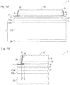
- FIG. 1A is a non-inventive modification of an optoelectronic semiconductor device 1 illustrated as a sectional view.
- the semiconductor component 1 comprises a semiconductor layer sequence 3 with an active layer 30.
- a radiation passage area 35 of the semiconductor layer sequence 3 exhibits a roughening to improve a light extraction from the semiconductor layer sequence 3.
- the active layer 30 of the semiconductor layer sequence 3 is set up to emit an ultraviolet, a near-infrared or a visible radiation, in particular blue light, during operation of the semiconductor component 1.
- the semiconductor layer sequence 3 may be based on GaN, InGaN, AlGaN, GaP, InGaAlP, InGaAs or GaAs.
- the metal mirror 4 is, for example, a silver mirror and is in direct contact with the semiconductor layer sequence 3.
- the semiconductor component 1 comprises a carrier 2.
- the carrier 2 includes a carrier substrate 23 which is made, for example, of a metal, a ceramic or of silicon or germanium.
- solder connection layers 22a, 22b adjoin the carrier substrate 23. At least one of the solder connection layers 22a, 22b is covered by the carrier 2 and applied to the carrier substrate 23.
- the solder connection layer 22a can be produced and / or applied to the semiconductor layer sequence 3.
- a metal layer 24 is located on a side of the carrier substrate 23 facing away from the semiconductor layer sequence 3. Via the metal layer 24, the semiconductor component 1 can be soldered, for example via surface mounting, to an external mounting carrier, not shown.
- the solder connection layer 22a and the semiconductor layer sequence 3 there is furthermore an encapsulation intermediate layer 21.
- the encapsulation intermediate layer 21 comprises or consists of TiWN.
- Both the carrier 2 and the semiconductor layer sequence 3 project beyond the metal mirror 4 in a lateral direction, preferably all around.
- the semiconductor layer sequence 3 and the carrier 2 project laterally beyond the metal mirror 4.
- the lateral boundary surfaces of the semiconductor layer sequence 3 represent, and at one of the metal mirror. 4 Uncovered, the carrier substrate 23 facing bottom of the semiconductor layer sequence 3 is an encapsulation layer 5.
- the encapsulation layer 5 is prepared by an atomic layer deposition method and preferably electrically insulating.
- a material of the encapsulation layer 5 preferably has a low refractive index in order to reflect a large proportion of radiation which strikes the encapsulation layer 5 via total reflection.
- Low refractive index may mean that the refractive index or the average refractive index of the encapsulation layer 5 is at most 1.7, preferably at most 1.6.
- the mean refractive index of the encapsulant layer is 5 ⁇ m at least 35% smaller than an average refractive index of the semiconductor layer sequence 3.
- a thickness of the semiconductor layer sequence 3 is preferably between 3 ⁇ m and 15 ⁇ m inclusive, in particular between 4 ⁇ m and 6 ⁇ m inclusive.
- the metal mirror 4 has a thickness of preferably between 100 nm and 150 nm inclusive.
- a thickness of the encapsulation layer 5 is according to FIG. 1 less than half of a thickness of the metal mirror 4, so that through the encapsulation layer 5 in the region in which the semiconductor layer sequence 3 and the carrier 2 laterally project beyond the metal mirror 4, a groove 7 is formed.
- the encapsulant layer 5 is then preferably between 30 nm and 70 nm thick.
- a thickness of the second mirror layer 6 is preferably between 50 nm and 250 nm inclusive.
- a thickness of the encapsulation intermediate layer 21 is, for example, between 200 nm and 1.5 ⁇ m inclusive.
- the solder bonding layers 22a, 22b, taken together, have, for example, a thickness of between 1 ⁇ m and 6 ⁇ m, and are formed or consist in particular of Au, Zn, Ni and / or In.
- the support substrate 23 preferably has a thickness of between 50 ⁇ m and 500 ⁇ m, in particular between 75 ⁇ m and 200 ⁇ m.
- the metallic contact layers 24, which are made of, for example, Au or an Au alloy, have, for example, a thickness of between 50 nm and 300 nm inclusive.
- the semiconductor device 1 can be produced as follows: On a not shown growth substrate is the Semiconductor layer sequence 3, for example epitaxially grown. Moreover, on a side of the semiconductor layer sequence 3 facing away from the growth substrate, the metal mirror 4 and the second mirror layer 6 are for example printed, vapor-deposited or deposited by a galvanic process. Furthermore, the encapsulation intermediate layer 21 is applied to the second mirror layer 6, on which in turn the solder connection layer 22a is produced.
- the carrier 2 with the solder connection layer 22 b, the carrier substrate 23 and the metallic contact layer 24 is provided. Before or even after a detachment of the semiconductor layer sequence 3 from the growth substrate, not shown, the solder connection layers 22a, 22b are soldered to each other, whereby the support 2 is firmly connected to the semiconductor layer sequence 3. Likewise, the carrier 2 may be applied galvanically to the semiconductor layer sequence 3.
- a mask for example in the form of a photoresist, is applied to the semiconductor layer sequence 3.
- the flanks 32 of the semiconductor layer sequence 3 are then produced by etching, for example, and the semiconductor layer sequence 3 is patterned in their lateral dimensions.
- the metal mirror 4 is then preferably structured with another etching method and its lateral dimensions are determined. As a result of this structuring, the supernatant of the semiconductor layer sequence 3 is generated via the metal mirror 4.
- a structuring of the Semiconductor layer sequence 3 and the metal mirror 4 is thus preferably carried out over the same mask in successive etching steps. For example, after removing the mask (not shown), the patterning on the radiation passage area 35 can then be generated.
- the encapsulation layer 5 is produced via an atomic layer deposition.
- the radiation passage area 35 preferably remains free from the encapsulation layer 5.
- the encapsulation layer 5 comprises one or more unselected individual layers with or made of a silicon dioxide and / or an aluminum oxide, wherein the layers each have a thickness between preferably including 2 nm and 8 nm and a Total thickness of the encapsulation layer 5 is preferably between 30 nm and 70 nm inclusive.
- individual layers of SiO 2 and Al 2 O 3 are arranged alternately.
- a lateral projection L of the semiconductor layer sequence 3 via the metal mirror 4 is preferably between 100 nm and 5 ⁇ m inclusive.
- the lateral projection L is preferably less than 1 ⁇ m or less than 0.5 ⁇ m.
- Such small protrusions L can be realized by structuring the semiconductor layer sequence 3 and the metal mirror 4 by means of the same mask, not shown, so that the structuring of the metal mirror and the semiconductor layer sequence 3 relative to each other takes place precisely.
- the encapsulation layer 5 is preferably transparent and absorbs an electromagnetic generated, for example, in the semiconductor layer sequence 3 Radiation not or only negligible. If the active layer is set up to generate radiation, a portion of the radiation generated in the active layer 30 can pass through the encapsulation layer 5 with little loss and be reflected back at the second mirror layer 6, for example in the direction of the radiation passage area 35. As a result, a coupling-out efficiency of the radiation from the semiconductor component 1 increases.
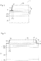
- FIG. 1B a detail view of the encapsulation layer 5 is shown. Furthermore, according to FIG. 1B applied to the encapsulation layer 5, a protective layer 50.
- a thickness of the protective layer 50 is, for example, between 100 nm and 400 nm inclusive.
- the protective layer 50 is made, for example, via CVD or PVD.
- a CVD or PVD is generally not able to completely fill the groove 7 with a material. In this way, in the area in which the semiconductor layer sequence 3 and the carrier 2 project laterally beyond the metal mirror 4, a cavity which is enclosed by the encapsulation layer 5 and the protective layer 50 remains behind.
- the encapsulation layer 5 formed by ALD and the protection layer 50 formed by CVD or PVD differ in that a defect density in the ALD encapsulation layer 5 is typically smaller than 0.1 defects per square millimeter, whereas the CVD or PVD protection layer 50 is one Defect density of some 100 defects per square millimeter. This is detectable, for example, by transmission electron microscopy, TEM for short. Due to the comparatively lower defect density of the ALD encapsulation layer 5, an etching rate is also reduced compared to the CVD or PVD protection layer 50. In particular, this is the case if the encapsulation layer 5 and the protective layer 50 consist of or comprise aluminum oxide. For example, on the defect density and / or the etching rate can be determined which of the layers 5, 50 was generated by which method.
- the encapsulation layer 5 has grown so thickly over ALD that a sub-layer grown from the semiconductor layer sequence 3 and a sub-layer of the encapsulation layer 5 grown from the second mirror layer 6 touch and form a seam 8. This ensures a particularly efficient encapsulation of the metal mirror 4 with respect to oxygen and / or water.
- FIG. 3 is a sectional view of a non-inventive modification of a semiconductor device illustrated.
- the metal mirror 4 is also surrounded in the lateral direction by the encapsulation intermediate layer 21.
- the encapsulation intermediate layer 21 consists, for example, of TiWN which exhibits a black or brownish coloration, then radiation generated in the semiconductor layer sequence 3, for example, is strongly absorbed at the encapsulation intermediate layer 21 and is not coupled out of the semiconductor component.
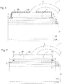
- FIG. 4 At the radiation passage surface 35, a bonding wire 9 is attached. An energization of the semiconductor device 1 then takes place via the metallic contact layer 24 and via the bonding wire 9.
- the semiconductor component 1 comprises two metallic contact layers 24, which are each guided via electrical plated-through holes 10 to a side of the carrier substrate 23 facing the semiconductor layer sequence 3.
- An electrical contacting of a side of the semiconductor layer sequence 3 facing the carrier substrate 23 furthermore takes place via the electrical bridge 12, which bridges a recess 15 in the solder connection layers 22a, 22b and in the encapsulation intermediate layer 21.
- a side facing away from the carrier substrate 23 of the semiconductor layer sequence is electrically connected via an opening 11, which is filled with copper, for example.
- the encapsulation layer 5 is, for example, as in FIGS Figures 1B or 2 shown executed.
- the semiconductor layer sequence 3 may be surrounded by a potting 14.
- the casting 14 can be at least one conversion means, at least one diffusion agent and / or at least one filter medium to be added.
- the carrier substrate 23 can optionally, as in the other examples, an integrated electrical functional element 13, which is designed for example as a protective device against electrostatic discharge.
- the encapsulation layer 5 completely or almost completely covers the radiation passage area 35, in particular with the exception of an optional connection area for the bonding wire 9.
- the encapsulation layer 5 consists of a material transparent to at least a portion of the radiation generated in the semiconductor layer sequence 3 or contains such a material.
- the encapsulant layer 5 then comprises or consists of silicon dioxide, wherein the silicon dioxide may be doped.
- a doping is carried out in particular with aluminum having a dopant concentration of preferably at most 1000 ppm or at most 100 ppm, where ppm stands for parts per million.
- the encapsulation layer 5 extends exclusively or essentially onto the groove 7. Unlike in FIG. 7 it is also possible for the encapsulation layer 5 to also partially extend to the flanks 32 of the semiconductor layer sequence 3, wherein the encapsulation layer 5, however, then does not reach the active layer 30 or, in a direction away from the carrier substrate 23, does not exceed. Likewise, parts of the encapsulation intermediate layer 21 located outside the groove 7 may also be covered by the encapsulation layer 5.
- the encapsulant layer 5 is made of one or more of the following materials: a transparent conductive oxide such as indium tin oxide, a pure metal such as tungsten.
- Such an encapsulation layer 5, as in FIG. 7 can be produced by a material for the encapsulation layer 5 is applied only in particular to the entire semiconductor layer sequence 3, similar to the embodiment according to FIG. 6 , and subsequently the material is removed in places.
Landscapes
- Engineering & Computer Science (AREA)
- Computer Hardware Design (AREA)
- Microelectronics & Electronic Packaging (AREA)
- Power Engineering (AREA)
- Led Device Packages (AREA)
- Led Devices (AREA)
Applications Claiming Priority (2)
| Application Number | Priority Date | Filing Date | Title |
|---|---|---|---|
| DE102009033686A DE102009033686A1 (de) | 2009-07-17 | 2009-07-17 | Optoelektronisches Halbleiterbauteil und Verfahren zur Herstellung eines anorganischen optoelektronischen Halbleiterbauteils |
| PCT/EP2010/058160 WO2011006719A1 (de) | 2009-07-17 | 2010-06-10 | Optoelektronisches halbleiterbauteil und verfahren zur herstellung eines anorganischen optoelektronischen halbleiterbauteils |
Publications (2)
| Publication Number | Publication Date |
|---|---|
| EP2454763A1 EP2454763A1 (de) | 2012-05-23 |
| EP2454763B1 true EP2454763B1 (de) | 2017-01-18 |
Family
ID=42671937
Family Applications (1)
| Application Number | Title | Priority Date | Filing Date |
|---|---|---|---|
| EP10724846.0A Not-in-force EP2454763B1 (de) | 2009-07-17 | 2010-06-10 | Optoelektronisches halbleiterbauteil und verfahren zur herstellung eines anorganischen optoelektronischen halbleiterbauteils |
Country Status (8)
Families Citing this family (29)
| Publication number | Priority date | Publication date | Assignee | Title |
|---|---|---|---|---|
| DE102009058796A1 (de) | 2009-12-18 | 2011-06-22 | OSRAM Opto Semiconductors GmbH, 93055 | Optoelektronisches Bauelement und Verfahren zur Herstellung eines optoelektronischen Bauelements |
| DE102010009717A1 (de) | 2010-03-01 | 2011-09-01 | Osram Opto Semiconductors Gmbh | Leuchtdiodenchip |
| WO2012035135A1 (de) | 2010-09-19 | 2012-03-22 | Osram Opto Semiconductors Gmbh | Halbleiterchip und verfahren zu dessen herstellung |
| DE102011010504A1 (de) * | 2011-02-07 | 2012-08-09 | Osram Opto Semiconductors Gmbh | Optoelektrischer Halbleiterchip |
| DE102011010503A1 (de) * | 2011-02-07 | 2012-08-09 | Osram Opto Semiconductors Gmbh | Optoelektronischer Halbleiterchip |
| DE102011011140A1 (de) | 2011-02-14 | 2012-08-16 | Osram Opto Semiconductors Gmbh | Optoelektronischer Halbleiterchip und Verfahren zur Herstellung von optoelektronischen Halbleiterchips |
| DE102011016302A1 (de) * | 2011-04-07 | 2012-10-11 | Osram Opto Semiconductors Gmbh | Optoelektronischer Halbleiterchip |
| US9196803B2 (en) * | 2011-04-11 | 2015-11-24 | Nichia Corporation | Semiconductor light emitting element and method for manufacturing the same |
| TWI548118B (zh) * | 2011-07-12 | 2016-09-01 | 廣鎵光電股份有限公司 | 發光元件及其製作方法 |
| TWI488337B (zh) * | 2011-07-12 | 2015-06-11 | Huga Optotech Inc | 發光元件及其製作方法 |
| DE102011112000B4 (de) | 2011-08-31 | 2023-11-30 | OSRAM Opto Semiconductors Gesellschaft mit beschränkter Haftung | Leuchtdiodenchip |
| US8646505B2 (en) | 2011-11-18 | 2014-02-11 | LuxVue Technology Corporation | Micro device transfer head |
| US8349116B1 (en) | 2011-11-18 | 2013-01-08 | LuxVue Technology Corporation | Micro device transfer head heater assembly and method of transferring a micro device |
| US8573469B2 (en) | 2011-11-18 | 2013-11-05 | LuxVue Technology Corporation | Method of forming a micro LED structure and array of micro LED structures with an electrically insulating layer |
| US8809875B2 (en) | 2011-11-18 | 2014-08-19 | LuxVue Technology Corporation | Micro light emitting diode |
| DE102012101889A1 (de) * | 2012-03-06 | 2013-09-12 | Osram Opto Semiconductors Gmbh | Verfahren zur Herstellung eines optoelektronischen Halbleiterchips und optoelektronischer Halbleiterchip |
| JP6135213B2 (ja) * | 2012-04-18 | 2017-05-31 | 日亜化学工業株式会社 | 半導体発光素子 |
| DE102012108879B4 (de) | 2012-09-20 | 2024-03-28 | OSRAM Opto Semiconductors Gesellschaft mit beschränkter Haftung | Optoelektronischer Halbleiterchip mit mehreren nebeneinander angeordneten aktiven Bereichen |
| DE102013100818B4 (de) * | 2013-01-28 | 2023-07-27 | OSRAM Opto Semiconductors Gesellschaft mit beschränkter Haftung | Optoelektronischer Halbleiterchip und Verfahren zur Herstellung eines optoelektronischen Halbleiterchips |
| DE102013107531A1 (de) | 2013-07-16 | 2015-01-22 | Osram Opto Semiconductors Gmbh | Optoelektronischer Halbleiterchip |
| DE102013107967B4 (de) * | 2013-07-25 | 2021-05-06 | OSRAM Opto Semiconductors Gesellschaft mit beschränkter Haftung | Optoelektronischer Halbleiterchip, optoelektronisches Bauelement und Verfahren zur Herstellung einer Mehrzahl von optoelektronischen Halbleiterchips |
| DE102014111482A1 (de) * | 2014-08-12 | 2016-02-18 | Osram Opto Semiconductors Gmbh | Optoelektronischer Halbleiterchip und Verfahren zu dessen Herstellung |
| CN104659165B (zh) * | 2015-02-11 | 2018-09-25 | 山东浪潮华光光电子股份有限公司 | 一种GaN基发光二极管芯片的制备方法 |
| DE102015112280A1 (de) | 2015-07-28 | 2017-02-02 | Osram Opto Semiconductors Gmbh | Bauelement mit einem metallischen Träger und Verfahren zur Herstellung von Bauelementen |
| DE102015118041A1 (de) | 2015-10-22 | 2017-04-27 | Osram Opto Semiconductors Gmbh | Leuchtdiodenchip und Verfahren zur Herstellung eines Leuchtdiodenchips |
| DE102016105056A1 (de) * | 2016-03-18 | 2017-09-21 | Osram Opto Semiconductors Gmbh | Verfahren zur Herstellung eines optoelektronischen Halbleiterchips und optoelektronischer Halbleiterchip |
| DE102016106928A1 (de) * | 2016-04-14 | 2017-10-19 | Osram Opto Semiconductors Gmbh | Optoelektronischer Halbleiterchip und Verfahren zur Herstellung eines optoelektronischen Halbleiterchips |
| DE102018107673A1 (de) | 2018-03-15 | 2019-09-19 | Osram Opto Semiconductors Gmbh | Optoelektronischer Halbleiterchip und Herstellungsverfahren für einen optoelektronischen Halbleiterchip |
| US11799058B2 (en) | 2018-03-15 | 2023-10-24 | Osram Oled Gmbh | Optoelectronic semiconductor chip |
Citations (2)
| Publication number | Priority date | Publication date | Assignee | Title |
|---|---|---|---|---|
| US20040169181A1 (en) * | 2002-06-26 | 2004-09-02 | Yoo Myung Cheol | Thin film light emitting diode |
| WO2009084670A1 (ja) * | 2007-12-28 | 2009-07-09 | Nichia Corporation | 半導体発光素子およびその製造方法 |
Family Cites Families (24)
| Publication number | Priority date | Publication date | Assignee | Title |
|---|---|---|---|---|
| SE393967B (sv) | 1974-11-29 | 1977-05-31 | Sateko Oy | Forfarande och for utforande av stroleggning mellan lagren i ett virkespaket |
| JPH05235406A (ja) | 1992-02-26 | 1993-09-10 | Kyocera Corp | 半導体発光素子 |
| EP2262007B1 (en) | 2002-01-28 | 2016-11-23 | Nichia Corporation | Nitride semiconductor element with supporting substrate |
| JP4165227B2 (ja) * | 2003-01-07 | 2008-10-15 | 株式会社デンソー | 有機el表示装置 |
| JP4325232B2 (ja) * | 2003-03-18 | 2009-09-02 | 日亜化学工業株式会社 | 窒化物半導体素子 |
| FR2861386B1 (fr) | 2003-10-23 | 2006-02-17 | Saint Gobain | Substrat, notamment substrat verrier, portant une couche a propriete photocatalytique revetue d'une couche mince protectrice. |
| US7091365B2 (en) | 2004-03-08 | 2006-08-15 | Abb Lummus Global Inc. | Process for olefin epoxidation and co-production of nylon precursor |
| US8174037B2 (en) * | 2004-09-22 | 2012-05-08 | Cree, Inc. | High efficiency group III nitride LED with lenticular surface |
| JP2006100500A (ja) | 2004-09-29 | 2006-04-13 | Sanken Electric Co Ltd | 半導体発光素子及びその製造方法 |
| JP5016808B2 (ja) * | 2005-11-08 | 2012-09-05 | ローム株式会社 | 窒化物半導体発光素子及び窒化物半導体発光素子製造方法 |
| KR100640496B1 (ko) | 2005-11-23 | 2006-11-01 | 삼성전기주식회사 | 수직구조 질화갈륨계 발광다이오드 소자 |
| US7622746B1 (en) * | 2006-03-17 | 2009-11-24 | Bridgelux, Inc. | Highly reflective mounting arrangement for LEDs |
| JP2007273590A (ja) | 2006-03-30 | 2007-10-18 | Rohm Co Ltd | 窒化物半導体素子及び窒化物半導体素子の製造方法 |
| JP4203087B2 (ja) * | 2006-07-25 | 2008-12-24 | 株式会社沖データ | 半導体複合装置、ledプリントヘッド及び画像形成装置 |
| US20080087875A1 (en) | 2006-10-11 | 2008-04-17 | Feng-Hsu Fan | Protection for the epitaxial structure of metal devices |
| JP5113478B2 (ja) | 2006-10-13 | 2013-01-09 | 三洋電機株式会社 | 半導体発光素子、照明装置および半導体発光素子の製造方法 |
| KR100867541B1 (ko) * | 2006-11-14 | 2008-11-06 | 삼성전기주식회사 | 수직형 발광 소자의 제조 방법 |
| DE102007004304A1 (de) | 2007-01-29 | 2008-07-31 | Osram Opto Semiconductors Gmbh | Dünnfilm-Leuchtdioden-Chip und Verfahren zur Herstellung eines Dünnfilm-Leuchtdioden-Chips |
| DE102007022947B4 (de) | 2007-04-26 | 2022-05-05 | OSRAM Opto Semiconductors Gesellschaft mit beschränkter Haftung | Optoelektronischer Halbleiterkörper und Verfahren zur Herstellung eines solchen |
| DE102007029370A1 (de) | 2007-05-04 | 2008-11-06 | Osram Opto Semiconductors Gmbh | Halbleiterchip und Verfahren zur Herstellung eines Halbleiterchips |
| JP4879094B2 (ja) * | 2007-06-06 | 2012-02-15 | 浜松ホトニクス株式会社 | 半導体発光素子及びその製造方法 |
| KR101371511B1 (ko) | 2007-10-04 | 2014-03-11 | 엘지이노텍 주식회사 | 수직형 발광 소자 |
| WO2009048799A1 (en) * | 2007-10-11 | 2009-04-16 | Jie Yao | Photo-detector array and semiconductor image intensifier |
| US8144743B2 (en) * | 2008-03-05 | 2012-03-27 | Rohm Co., Ltd. | Nitride based semiconductor device and fabrication method for the same |
-
2009
- 2009-07-17 DE DE102009033686A patent/DE102009033686A1/de not_active Withdrawn
-
2010
- 2010-06-10 JP JP2012519952A patent/JP5755646B2/ja not_active Expired - Fee Related
- 2010-06-10 WO PCT/EP2010/058160 patent/WO2011006719A1/de active Application Filing
- 2010-06-10 US US13/318,800 patent/US8698178B2/en active Active
- 2010-06-10 CN CN201080029752.0A patent/CN102473810B/zh not_active Expired - Fee Related
- 2010-06-10 KR KR1020127004141A patent/KR101614106B1/ko not_active Expired - Fee Related
- 2010-06-10 EP EP10724846.0A patent/EP2454763B1/de not_active Not-in-force
- 2010-07-13 TW TW099122953A patent/TWI423486B/zh not_active IP Right Cessation
Patent Citations (2)
| Publication number | Priority date | Publication date | Assignee | Title |
|---|---|---|---|---|
| US20040169181A1 (en) * | 2002-06-26 | 2004-09-02 | Yoo Myung Cheol | Thin film light emitting diode |
| WO2009084670A1 (ja) * | 2007-12-28 | 2009-07-09 | Nichia Corporation | 半導体発光素子およびその製造方法 |
Also Published As
| Publication number | Publication date |
|---|---|
| US8698178B2 (en) | 2014-04-15 |
| TW201115793A (en) | 2011-05-01 |
| KR20120052327A (ko) | 2012-05-23 |
| JP2012533873A (ja) | 2012-12-27 |
| JP5755646B2 (ja) | 2015-07-29 |
| US20120098016A1 (en) | 2012-04-26 |
| TWI423486B (zh) | 2014-01-11 |
| DE102009033686A1 (de) | 2011-01-20 |
| CN102473810B (zh) | 2015-09-23 |
| WO2011006719A1 (de) | 2011-01-20 |
| KR101614106B1 (ko) | 2016-04-20 |
| CN102473810A (zh) | 2012-05-23 |
| EP2454763A1 (de) | 2012-05-23 |
Similar Documents
| Publication | Publication Date | Title |
|---|---|---|
| EP2454763B1 (de) | Optoelektronisches halbleiterbauteil und verfahren zur herstellung eines anorganischen optoelektronischen halbleiterbauteils | |
| EP1886360B1 (de) | Lumineszenzdiodenchip mit einer kontaktstruktur | |
| DE102010024079B4 (de) | Verfahren zur Herstellung eines optoelektronischen Halbleiterchips und optoelektronischer Halbleiterchip | |
| DE102006046449B4 (de) | Verfahren zur Herstellung einer vertikal strukturierten Leuchtdiode | |
| EP2612372B1 (de) | Leuchtdiodenchip | |
| EP1284026A1 (de) | Lumineszenzdiodenchip mit einer auf gan basierenden strahlungsemittierenden epitaxieschichtenfolge und verfahren zu dessen herstellung | |
| EP1709694B1 (de) | Dünnfilm-led mit einer stromaufweitungsstruktur | |
| DE102007029370A1 (de) | Halbleiterchip und Verfahren zur Herstellung eines Halbleiterchips | |
| DE102007004302A1 (de) | Halbleiterchip und Verfahren zur Herstellung eines Halbleiterchips | |
| DE102012108879B4 (de) | Optoelektronischer Halbleiterchip mit mehreren nebeneinander angeordneten aktiven Bereichen | |
| DE102007032555A1 (de) | Halbleiterchip und Verfahren zur Herstellung eines Halbleiterchips | |
| EP2057696B1 (de) | Optoelektronischer halbleiterchip und verfahren zur dessen herstellung | |
| WO2017089198A1 (de) | Leuchtdiodenchip mit einer reflektierenden schichtenfolge | |
| DE102010049186B4 (de) | Optoelektronisches Bauelement und Verfahren zu dessen Herstellung | |
| WO2015177164A1 (de) | Verfahren zur herstellung eines optoelektronischen halbleiterchips sowie optoelektronischer halbleiterchip | |
| WO2018114807A1 (de) | Optoelektronischer halbleiterchip und verfahren zur herstellung eines optoelektronischen halbleiterchips | |
| WO2012107289A1 (de) | Optoelektronischer halbleiterchip mit verkapselter spiegelschicht | |
| EP1770792A2 (de) | Strahlungsemittierender Halbleiterchip | |
| WO2019020424A1 (de) | Optoelektronischer halbleiterchip, hochvolthalbleiterchip und verfahren zur herstellung eines optoelektronischen halbleiterchips | |
| DE102011010504A1 (de) | Optoelektrischer Halbleiterchip | |
| EP1592070B1 (de) | Strahlungsemittierendes und/oder -empfangendes Halbleiterbauelement und Verfahren zur strukturierten Aufbringung eines Kontakts auf einen Halbleiterkörper | |
| DE102016124860A1 (de) | Optoelektronischer Halbleiterchip und Verfahren zur Herstellung eines optoelektronischen Halbleiterchips | |
| WO2012139953A1 (de) | Verfahren zur herstellung eines halbleiterkörpers | |
| WO2014072410A1 (de) | Optoelektronischer halbleiterchip und verfahren zur herstellung eines optoelektronischen halbleiterchips | |
| WO2021043901A1 (de) | Optoelektronisches bauelement und verfahren zur herstellung eines optoelektronischen bauelements |
Legal Events
| Date | Code | Title | Description |
|---|---|---|---|
| PUAI | Public reference made under article 153(3) epc to a published international application that has entered the european phase |
Free format text: ORIGINAL CODE: 0009012 |
|
| 17P | Request for examination filed |
Effective date: 20111024 |
|
| AK | Designated contracting states |
Kind code of ref document: A1 Designated state(s): AL AT BE BG CH CY CZ DE DK EE ES FI FR GB GR HR HU IE IS IT LI LT LU LV MC MK MT NL NO PL PT RO SE SI SK SM TR |
|
| DAX | Request for extension of the european patent (deleted) | ||
| 17Q | First examination report despatched |
Effective date: 20160705 |
|
| GRAP | Despatch of communication of intention to grant a patent |
Free format text: ORIGINAL CODE: EPIDOSNIGR1 |
|
| RIC1 | Information provided on ipc code assigned before grant |
Ipc: H01L 33/00 20100101ALN20160928BHEP Ipc: H01L 23/00 20060101ALI20160928BHEP Ipc: H01L 33/44 20100101AFI20160928BHEP Ipc: H01L 33/40 20100101ALN20160928BHEP |
|
| RIC1 | Information provided on ipc code assigned before grant |
Ipc: H01L 23/00 20060101ALI20161004BHEP Ipc: H01L 33/40 20100101ALN20161004BHEP Ipc: H01L 33/44 20100101AFI20161004BHEP Ipc: H01L 33/00 20100101ALN20161004BHEP |
|
| INTG | Intention to grant announced |
Effective date: 20161018 |
|
| GRAS | Grant fee paid |
Free format text: ORIGINAL CODE: EPIDOSNIGR3 |
|
| GRAA | (expected) grant |
Free format text: ORIGINAL CODE: 0009210 |
|
| AK | Designated contracting states |
Kind code of ref document: B1 Designated state(s): AL AT BE BG CH CY CZ DE DK EE ES FI FR GB GR HR HU IE IS IT LI LT LU LV MC MK MT NL NO PL PT RO SE SI SK SM TR |
|
| REG | Reference to a national code |
Ref country code: GB Ref legal event code: FG4D Free format text: NOT ENGLISH |
|
| REG | Reference to a national code |
Ref country code: CH Ref legal event code: EP |
|
| REG | Reference to a national code |
Ref country code: AT Ref legal event code: REF Ref document number: 863357 Country of ref document: AT Kind code of ref document: T Effective date: 20170215 |
|
| REG | Reference to a national code |
Ref country code: IE Ref legal event code: FG4D Free format text: LANGUAGE OF EP DOCUMENT: GERMAN |
|
| REG | Reference to a national code |
Ref country code: DE Ref legal event code: R096 Ref document number: 502010013078 Country of ref document: DE |
|
| REG | Reference to a national code |
Ref country code: NL Ref legal event code: MP Effective date: 20170118 |
|
| REG | Reference to a national code |
Ref country code: LT Ref legal event code: MG4D |
|
| PG25 | Lapsed in a contracting state [announced via postgrant information from national office to epo] |
Ref country code: NL Free format text: LAPSE BECAUSE OF FAILURE TO SUBMIT A TRANSLATION OF THE DESCRIPTION OR TO PAY THE FEE WITHIN THE PRESCRIBED TIME-LIMIT Effective date: 20170118 |
|
| PG25 | Lapsed in a contracting state [announced via postgrant information from national office to epo] |
Ref country code: HR Free format text: LAPSE BECAUSE OF FAILURE TO SUBMIT A TRANSLATION OF THE DESCRIPTION OR TO PAY THE FEE WITHIN THE PRESCRIBED TIME-LIMIT Effective date: 20170118 Ref country code: GR Free format text: LAPSE BECAUSE OF FAILURE TO SUBMIT A TRANSLATION OF THE DESCRIPTION OR TO PAY THE FEE WITHIN THE PRESCRIBED TIME-LIMIT Effective date: 20170419 Ref country code: FI Free format text: LAPSE BECAUSE OF FAILURE TO SUBMIT A TRANSLATION OF THE DESCRIPTION OR TO PAY THE FEE WITHIN THE PRESCRIBED TIME-LIMIT Effective date: 20170118 Ref country code: LT Free format text: LAPSE BECAUSE OF FAILURE TO SUBMIT A TRANSLATION OF THE DESCRIPTION OR TO PAY THE FEE WITHIN THE PRESCRIBED TIME-LIMIT Effective date: 20170118 Ref country code: NO Free format text: LAPSE BECAUSE OF FAILURE TO SUBMIT A TRANSLATION OF THE DESCRIPTION OR TO PAY THE FEE WITHIN THE PRESCRIBED TIME-LIMIT Effective date: 20170418 Ref country code: IS Free format text: LAPSE BECAUSE OF FAILURE TO SUBMIT A TRANSLATION OF THE DESCRIPTION OR TO PAY THE FEE WITHIN THE PRESCRIBED TIME-LIMIT Effective date: 20170518 |
|
| PG25 | Lapsed in a contracting state [announced via postgrant information from national office to epo] |
Ref country code: PL Free format text: LAPSE BECAUSE OF FAILURE TO SUBMIT A TRANSLATION OF THE DESCRIPTION OR TO PAY THE FEE WITHIN THE PRESCRIBED TIME-LIMIT Effective date: 20170118 Ref country code: BG Free format text: LAPSE BECAUSE OF FAILURE TO SUBMIT A TRANSLATION OF THE DESCRIPTION OR TO PAY THE FEE WITHIN THE PRESCRIBED TIME-LIMIT Effective date: 20170418 Ref country code: ES Free format text: LAPSE BECAUSE OF FAILURE TO SUBMIT A TRANSLATION OF THE DESCRIPTION OR TO PAY THE FEE WITHIN THE PRESCRIBED TIME-LIMIT Effective date: 20170118 Ref country code: LV Free format text: LAPSE BECAUSE OF FAILURE TO SUBMIT A TRANSLATION OF THE DESCRIPTION OR TO PAY THE FEE WITHIN THE PRESCRIBED TIME-LIMIT Effective date: 20170118 Ref country code: PT Free format text: LAPSE BECAUSE OF FAILURE TO SUBMIT A TRANSLATION OF THE DESCRIPTION OR TO PAY THE FEE WITHIN THE PRESCRIBED TIME-LIMIT Effective date: 20170518 Ref country code: SE Free format text: LAPSE BECAUSE OF FAILURE TO SUBMIT A TRANSLATION OF THE DESCRIPTION OR TO PAY THE FEE WITHIN THE PRESCRIBED TIME-LIMIT Effective date: 20170118 |
|
| REG | Reference to a national code |
Ref country code: DE Ref legal event code: R097 Ref document number: 502010013078 Country of ref document: DE |
|
| PG25 | Lapsed in a contracting state [announced via postgrant information from national office to epo] |
Ref country code: RO Free format text: LAPSE BECAUSE OF FAILURE TO SUBMIT A TRANSLATION OF THE DESCRIPTION OR TO PAY THE FEE WITHIN THE PRESCRIBED TIME-LIMIT Effective date: 20170118 Ref country code: SK Free format text: LAPSE BECAUSE OF FAILURE TO SUBMIT A TRANSLATION OF THE DESCRIPTION OR TO PAY THE FEE WITHIN THE PRESCRIBED TIME-LIMIT Effective date: 20170118 Ref country code: CZ Free format text: LAPSE BECAUSE OF FAILURE TO SUBMIT A TRANSLATION OF THE DESCRIPTION OR TO PAY THE FEE WITHIN THE PRESCRIBED TIME-LIMIT Effective date: 20170118 Ref country code: EE Free format text: LAPSE BECAUSE OF FAILURE TO SUBMIT A TRANSLATION OF THE DESCRIPTION OR TO PAY THE FEE WITHIN THE PRESCRIBED TIME-LIMIT Effective date: 20170118 Ref country code: IT Free format text: LAPSE BECAUSE OF FAILURE TO SUBMIT A TRANSLATION OF THE DESCRIPTION OR TO PAY THE FEE WITHIN THE PRESCRIBED TIME-LIMIT Effective date: 20170118 |
|
| PLBE | No opposition filed within time limit |
Free format text: ORIGINAL CODE: 0009261 |
|
| STAA | Information on the status of an ep patent application or granted ep patent |
Free format text: STATUS: NO OPPOSITION FILED WITHIN TIME LIMIT |
|
| PG25 | Lapsed in a contracting state [announced via postgrant information from national office to epo] |
Ref country code: DK Free format text: LAPSE BECAUSE OF FAILURE TO SUBMIT A TRANSLATION OF THE DESCRIPTION OR TO PAY THE FEE WITHIN THE PRESCRIBED TIME-LIMIT Effective date: 20170118 Ref country code: SM Free format text: LAPSE BECAUSE OF FAILURE TO SUBMIT A TRANSLATION OF THE DESCRIPTION OR TO PAY THE FEE WITHIN THE PRESCRIBED TIME-LIMIT Effective date: 20170118 |
|
| 26N | No opposition filed |
Effective date: 20171019 |
|
| PG25 | Lapsed in a contracting state [announced via postgrant information from national office to epo] |
Ref country code: MC Free format text: LAPSE BECAUSE OF FAILURE TO SUBMIT A TRANSLATION OF THE DESCRIPTION OR TO PAY THE FEE WITHIN THE PRESCRIBED TIME-LIMIT Effective date: 20170118 |
|
| REG | Reference to a national code |
Ref country code: CH Ref legal event code: PL |
|
| GBPC | Gb: european patent ceased through non-payment of renewal fee |
Effective date: 20170610 |
|
| PG25 | Lapsed in a contracting state [announced via postgrant information from national office to epo] |
Ref country code: SI Free format text: LAPSE BECAUSE OF FAILURE TO SUBMIT A TRANSLATION OF THE DESCRIPTION OR TO PAY THE FEE WITHIN THE PRESCRIBED TIME-LIMIT Effective date: 20170118 |
|
| REG | Reference to a national code |
Ref country code: IE Ref legal event code: MM4A |
|
| REG | Reference to a national code |
Ref country code: FR Ref legal event code: ST Effective date: 20180228 |
|
| PG25 | Lapsed in a contracting state [announced via postgrant information from national office to epo] |
Ref country code: LU Free format text: LAPSE BECAUSE OF NON-PAYMENT OF DUE FEES Effective date: 20170610 Ref country code: LI Free format text: LAPSE BECAUSE OF NON-PAYMENT OF DUE FEES Effective date: 20170630 Ref country code: IE Free format text: LAPSE BECAUSE OF NON-PAYMENT OF DUE FEES Effective date: 20170610 Ref country code: GB Free format text: LAPSE BECAUSE OF NON-PAYMENT OF DUE FEES Effective date: 20170610 Ref country code: CH Free format text: LAPSE BECAUSE OF NON-PAYMENT OF DUE FEES Effective date: 20170630 |
|
| PG25 | Lapsed in a contracting state [announced via postgrant information from national office to epo] |
Ref country code: FR Free format text: LAPSE BECAUSE OF NON-PAYMENT OF DUE FEES Effective date: 20170630 |
|
| REG | Reference to a national code |
Ref country code: BE Ref legal event code: MM Effective date: 20170630 |
|
| REG | Reference to a national code |
Ref country code: AT Ref legal event code: MM01 Ref document number: 863357 Country of ref document: AT Kind code of ref document: T Effective date: 20170610 |
|
| PG25 | Lapsed in a contracting state [announced via postgrant information from national office to epo] |
Ref country code: BE Free format text: LAPSE BECAUSE OF NON-PAYMENT OF DUE FEES Effective date: 20170630 |
|
| PG25 | Lapsed in a contracting state [announced via postgrant information from national office to epo] |
Ref country code: MT Free format text: LAPSE BECAUSE OF FAILURE TO SUBMIT A TRANSLATION OF THE DESCRIPTION OR TO PAY THE FEE WITHIN THE PRESCRIBED TIME-LIMIT Effective date: 20170118 |
|
| PG25 | Lapsed in a contracting state [announced via postgrant information from national office to epo] |
Ref country code: AT Free format text: LAPSE BECAUSE OF NON-PAYMENT OF DUE FEES Effective date: 20170610 |
|
| PG25 | Lapsed in a contracting state [announced via postgrant information from national office to epo] |
Ref country code: HU Free format text: LAPSE BECAUSE OF FAILURE TO SUBMIT A TRANSLATION OF THE DESCRIPTION OR TO PAY THE FEE WITHIN THE PRESCRIBED TIME-LIMIT; INVALID AB INITIO Effective date: 20100610 |
|
| PG25 | Lapsed in a contracting state [announced via postgrant information from national office to epo] |
Ref country code: CY Free format text: LAPSE BECAUSE OF NON-PAYMENT OF DUE FEES Effective date: 20170118 |
|
| PG25 | Lapsed in a contracting state [announced via postgrant information from national office to epo] |
Ref country code: MK Free format text: LAPSE BECAUSE OF FAILURE TO SUBMIT A TRANSLATION OF THE DESCRIPTION OR TO PAY THE FEE WITHIN THE PRESCRIBED TIME-LIMIT Effective date: 20170118 |
|
| PG25 | Lapsed in a contracting state [announced via postgrant information from national office to epo] |
Ref country code: TR Free format text: LAPSE BECAUSE OF FAILURE TO SUBMIT A TRANSLATION OF THE DESCRIPTION OR TO PAY THE FEE WITHIN THE PRESCRIBED TIME-LIMIT Effective date: 20170118 |
|
| PG25 | Lapsed in a contracting state [announced via postgrant information from national office to epo] |
Ref country code: AL Free format text: LAPSE BECAUSE OF FAILURE TO SUBMIT A TRANSLATION OF THE DESCRIPTION OR TO PAY THE FEE WITHIN THE PRESCRIBED TIME-LIMIT Effective date: 20170118 |
|
| PGFP | Annual fee paid to national office [announced via postgrant information from national office to epo] |
Ref country code: DE Payment date: 20210618 Year of fee payment: 12 |
|
| REG | Reference to a national code |
Ref country code: DE Ref legal event code: R119 Ref document number: 502010013078 Country of ref document: DE |
|
| PG25 | Lapsed in a contracting state [announced via postgrant information from national office to epo] |
Ref country code: DE Free format text: LAPSE BECAUSE OF NON-PAYMENT OF DUE FEES Effective date: 20230103 |