EP2449332B1 - SPANN- UND ENTSPANNVORRICHTUNG FÜR EINE SCHUßWAFFE - Google Patents
SPANN- UND ENTSPANNVORRICHTUNG FÜR EINE SCHUßWAFFE Download PDFInfo
- Publication number
- EP2449332B1 EP2449332B1 EP10722907A EP10722907A EP2449332B1 EP 2449332 B1 EP2449332 B1 EP 2449332B1 EP 10722907 A EP10722907 A EP 10722907A EP 10722907 A EP10722907 A EP 10722907A EP 2449332 B1 EP2449332 B1 EP 2449332B1
- Authority
- EP
- European Patent Office
- Prior art keywords
- cocking
- mechanism according
- catch
- firing pin
- uncocking
- Prior art date
- Legal status (The legal status is an assumption and is not a legal conclusion. Google has not performed a legal analysis and makes no representation as to the accuracy of the status listed.)
- Not-in-force
Links
Images
Classifications
-
- F—MECHANICAL ENGINEERING; LIGHTING; HEATING; WEAPONS; BLASTING
- F41—WEAPONS
- F41A—FUNCTIONAL FEATURES OR DETAILS COMMON TO BOTH SMALLARMS AND ORDNANCE, e.g. CANNONS; MOUNTINGS FOR SMALLARMS OR ORDNANCE
- F41A19/00—Firing or trigger mechanisms; Cocking mechanisms
- F41A19/06—Mechanical firing mechanisms, e.g. counterrecoil firing, recoil actuated firing mechanisms
- F41A19/25—Mechanical firing mechanisms, e.g. counterrecoil firing, recoil actuated firing mechanisms having only slidably-mounted striker elements, i.e. percussion or firing pins
- F41A19/27—Mechanical firing mechanisms, e.g. counterrecoil firing, recoil actuated firing mechanisms having only slidably-mounted striker elements, i.e. percussion or firing pins the percussion or firing pin being movable relative to the breech-block
- F41A19/29—Mechanical firing mechanisms, e.g. counterrecoil firing, recoil actuated firing mechanisms having only slidably-mounted striker elements, i.e. percussion or firing pins the percussion or firing pin being movable relative to the breech-block propelled by a spring under tension
- F41A19/30—Mechanical firing mechanisms, e.g. counterrecoil firing, recoil actuated firing mechanisms having only slidably-mounted striker elements, i.e. percussion or firing pins the percussion or firing pin being movable relative to the breech-block propelled by a spring under tension in bolt-action guns
- F41A19/31—Sear arrangements therefor
-
- F—MECHANICAL ENGINEERING; LIGHTING; HEATING; WEAPONS; BLASTING
- F41—WEAPONS
- F41A—FUNCTIONAL FEATURES OR DETAILS COMMON TO BOTH SMALLARMS AND ORDNANCE, e.g. CANNONS; MOUNTINGS FOR SMALLARMS OR ORDNANCE
- F41A19/00—Firing or trigger mechanisms; Cocking mechanisms
- F41A19/06—Mechanical firing mechanisms, e.g. counterrecoil firing, recoil actuated firing mechanisms
- F41A19/12—Sears; Sear mountings
-
- F—MECHANICAL ENGINEERING; LIGHTING; HEATING; WEAPONS; BLASTING
- F41—WEAPONS
- F41A—FUNCTIONAL FEATURES OR DETAILS COMMON TO BOTH SMALLARMS AND ORDNANCE, e.g. CANNONS; MOUNTINGS FOR SMALLARMS OR ORDNANCE
- F41A19/00—Firing or trigger mechanisms; Cocking mechanisms
- F41A19/06—Mechanical firing mechanisms, e.g. counterrecoil firing, recoil actuated firing mechanisms
- F41A19/25—Mechanical firing mechanisms, e.g. counterrecoil firing, recoil actuated firing mechanisms having only slidably-mounted striker elements, i.e. percussion or firing pins
- F41A19/27—Mechanical firing mechanisms, e.g. counterrecoil firing, recoil actuated firing mechanisms having only slidably-mounted striker elements, i.e. percussion or firing pins the percussion or firing pin being movable relative to the breech-block
- F41A19/29—Mechanical firing mechanisms, e.g. counterrecoil firing, recoil actuated firing mechanisms having only slidably-mounted striker elements, i.e. percussion or firing pins the percussion or firing pin being movable relative to the breech-block propelled by a spring under tension
- F41A19/30—Mechanical firing mechanisms, e.g. counterrecoil firing, recoil actuated firing mechanisms having only slidably-mounted striker elements, i.e. percussion or firing pins the percussion or firing pin being movable relative to the breech-block propelled by a spring under tension in bolt-action guns
- F41A19/34—Cocking mechanisms
-
- F—MECHANICAL ENGINEERING; LIGHTING; HEATING; WEAPONS; BLASTING
- F41—WEAPONS
- F41A—FUNCTIONAL FEATURES OR DETAILS COMMON TO BOTH SMALLARMS AND ORDNANCE, e.g. CANNONS; MOUNTINGS FOR SMALLARMS OR ORDNANCE
- F41A19/00—Firing or trigger mechanisms; Cocking mechanisms
- F41A19/06—Mechanical firing mechanisms, e.g. counterrecoil firing, recoil actuated firing mechanisms
- F41A19/25—Mechanical firing mechanisms, e.g. counterrecoil firing, recoil actuated firing mechanisms having only slidably-mounted striker elements, i.e. percussion or firing pins
- F41A19/27—Mechanical firing mechanisms, e.g. counterrecoil firing, recoil actuated firing mechanisms having only slidably-mounted striker elements, i.e. percussion or firing pins the percussion or firing pin being movable relative to the breech-block
- F41A19/29—Mechanical firing mechanisms, e.g. counterrecoil firing, recoil actuated firing mechanisms having only slidably-mounted striker elements, i.e. percussion or firing pins the percussion or firing pin being movable relative to the breech-block propelled by a spring under tension
- F41A19/39—Cocking or firing mechanisms for other types of guns, e.g. fixed breech-block types, forwardly-slidable barrel types
- F41A19/41—Cocking or firing mechanisms for other types of guns, e.g. fixed breech-block types, forwardly-slidable barrel types for breakdown guns
Definitions
- the present invention relates to a tensioning and relaxing device for a firearm with spring-loaded firing pin which engages in the clamping position on a freed for firing trigger piece, the catching piece is displaceable by an actuating element between the clamping position and the firing pin spring relaxing securing position.
- tensioning and relaxing devices are used in particular for the temporary securing of an already loaded weapon, e.g. for transport or on the prowl. To leave the securing position, the catching piece must be re-tensioned against the force of the firing pin spring, which is why such safety devices simultaneously serve as a "hand tensioner".
- the actuating element is connected via a lever drive with the catching piece, via which the force is applied for tensioning the firing pin spring.
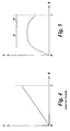
- This has the disadvantage that the force to be exerted on the actuating element F increases approximately linearly with the actuating travel S according to the spring characteristic of the firing pin spring, as in the diagram of FIG Fig. 4 shown.
- the actuator such as a cocking slide or wheel, extremely laborious.
- the actuating force is highest in the region around the clamping position, which makes it difficult to actuate any locking or release button for locking or releasing the actuating element in the clamping position.
- the invention has set itself the goal of creating a tensioning and relaxing device of the type mentioned with easier operation.
- This object is achieved according to the invention in that the actuating element acts on the catching piece via a linkage control, the control cam of which is to be applied to the actuating element for displacing the catching piece into the clamping position Force keeps substantially constant at least in the central region of the actuation path.
- the operation of the actuator e.g. a cocking slide or wheel
- the translation of the clamping drive between actuator and catching piece can be predefined path-dependent, u.zw. in particular so that the actuating force remains largely the same for the user at least over the central portion of the actuating path.
- control cam reduces the force to be applied to the actuating element in order to displace the catching piece in the end region of the actuating travel before reaching the tensioning position.
- a preferred embodiment of the invention is characterized in that the control cam is formed on the circumference of a driven by the actuating element pivoting gate, which is scanned by the catching piece driving Tastgestfite, which takes up only small space.
- Tastgestlinde is equipped with a preferably ball-bearing cam follower, which rolls on the control cam, whereby the friction of the slide control and thus the required operating force can be substantially reduced.
- the Tastgestlinde additionally engages in an auxiliary link guide of the link control in order to keep the cam follower during the return movement into the securing position in contact with the control cam. In this way, malfunctions, e.g. be avoided because of increased friction due to contamination, etc.
- the Tastgestlinde comprises a linearly movable probe rod, which scans the control cam at one end and drives the catching piece at the other end, preferably via a housing-mounted two-armed lever, which allows a particularly compact design with low space requirements.
- the actuator may be of any type known in the art, e.g. a cocking slide or tensioning wheel.
- the actuating element is a cocking slide, which is particularly preferably locked in the clamping position and by means of a push button from the latch can be solved.
- This known per se embodiment of a cocking slide allows supplementarysunanrize operation and locking in the clamping position and a meaningful Spend in the securing position.
- the tensioning and relaxing device of the invention is suitable for any type of firearm with spring-loaded firing pin. Particularly advantageous is the application of the invention in repeating weapons with rotary piston closure and especially in weapons whose firing pin has an attached firing pin flag which snaps on the catch piece, because here the tensioning and relaxing device of the invention can be attached directly without additional parts.
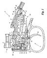
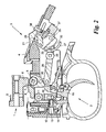
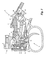
- a firing pin 1 acts on a cartridge in the cartridge chamber of a barrel and is performed for this purpose, for example, in a rotary piston closure, which parts are well known to the skilled person and therefore not shown here.
- the extraction device 2 comprises an intermediate element in the form of a locking rod 10 which is guided approximately vertically vertically in the housing 4 and carries at its upper end a ball-bearing roller 11 on which the catching piece 8 can slide back and forth ,
- the locking bar 10 in turn engages with a shoulder 12 at a locking edge 13 which is formed on a shoulder 14 of a trigger 15.
- the trigger 15 is pivotally mounted at 16 on the housing 4 and moves when pressed the locking edge 13 of the locking rod 10 so that it moves down ( Fig. 3 ) and the catching piece 8 from the firing pin 1 free Marie, whereby the shot is discharged.
- the extent of the locking overlap between the shoulder 12 of the locking rod 10 and the locking edge 13 of the trigger 15 can be adjusted by means of an adjusting screw 17.
- the trigger 15 with its locking edge 13 may be integrally or - as shown - made of two parts adjustable relative to each other, such as a toggle 18 comprehensive first part and the paragraph 14 with the locking edge 13 comprehensive second part.
- the trigger 15 may be further equipped with a drop guard 19 and a closure catch 20 for withdrawing a rotary piston closure, as known to those skilled in the art.
- the tensioning and relaxing device 3 comprises an actuating element 21 in the form of a slidingly mounted on the outside of the housing 4 cocking slide 21 with a thumb engaging surface 22 which acts via a drive 23 on the catching piece 8 to this in firing pin longitudinal direction between its two positions ( Fig. 1 and 2 ) to move back and forth.
- the drive 23 includes a slide control 24, via which the force / displacement ratio between the actuator 21 and the catching piece 8 can be defined.
- the slide control 24 comprises a pivoting gate 25, which is pivotable by the cocking slide 21 via a link 26 and carries on its outer periphery a cam 27.
- a TastgestShe 28 rolls off with a ball-bearing cam follower 29 and translates the shape of the control cam 27 via a housing-mounted two-armed lever 30, which engages a pin 31 of the catching piece 8, in a movement of the catching piece.
- the pivoting gate 25 is additionally equipped with an auxiliary link guide 32 in the form of a groove guide located behind the cam 27, in which the TastgestShe 28 engages with a cam follower 29 protruding retaining pin 33.
- Fig. 5 shows the force / displacement ratio of the gate controller 24, where R is the relaxation or securing position of Fig. 1 and C the unlocked or clamping position of Fig. 2 designated.
- R is the relaxation or securing position of Fig. 1 and C the unlocked or clamping position of Fig. 2 designated.
- the probe rod 28 slides on the cam 27 aufreitend to the left and the catching piece 8 moves through the lever 29 to the right against the force of the firing pin spring 5.
- the slope of the cam 27 is chosen so that the applied to the actuator 21 force F is at least in a central region 34 of the actuating travel R - C of the cocking slide 21 is substantially constant in order to facilitate the operation of the cocking slide 21.
- the cam 27 is preferably also chosen so that in the end region 35 of the actuating travel R - C before the clamping position C, the applied force F even decreases again. This allows a "cautious", noiseless reaching the clamping position C. Furthermore, this facilitates the operation of a push button 36 on the cocking slide 21, with which a seeinrastende latch 37 for locking the handlebar 26 in the clamping position C can be solved again.
- any other said translation function fulfilling slide control 23 can be used, for example, a kinematic reversal with control cam on catching and Tastgestfite on the actuating element, etc. Further, all rotary or pivot bearings in the device by means of Rolling carried out to reduce friction.
Landscapes
- Engineering & Computer Science (AREA)
- General Engineering & Computer Science (AREA)
- Clamps And Clips (AREA)
- Portable Nailing Machines And Staplers (AREA)
- Automotive Seat Belt Assembly (AREA)
- Mechanical Pencils And Projecting And Retracting Systems Therefor, And Multi-System Writing Instruments (AREA)
Description
- Die vorliegende Erfindung betrifft eine Spann- und Entspannvorrichtung für eine Schußwaffe mit federbelastetem Schlagbolzen, der in der Spannstellung an einem zur Schußabgabe freistellbaren Fangstück rastet, wobei das Fangstück durch ein Betätigungselement zwischen der Spannstellung und einer die Schlagbolzenfeder entspannenden Sicherungsstellung versetzbar ist.
- Derartige Spann- und Entspannvorrichtungen dienen insbesondere zum vorübergehenden Sichern einer bereits geladenen Waffe, z.B. für den Transport oder auf der Pirsch. Zum Verlassen der Sicherungsstellung muß das Fangstück gegen die Kraft der Schlagbolzenfeder wieder neu gespannt werden, weshalb solche Sicherheitsvorrichtungen gleichzeitig als "Handspanner" dienen.
- Bei den bekannten Konstruktionen (z.B.
AT 409 548 B Fig. 4 dargestellt. Dies macht die Bedienung des Betätigungselementes, z.B. eines Spannschiebers oder -rads, äußerst mühevoll. Darüber hinaus ist die Betätigungskraft gerade im Bereich um die Spannstellung am höchsten, was dort das Betätigen eines allfälligen Rast- oder Löseknopfes für das Verrasten bzw. Lösen des Betätigungselements in der Spannstellung erschwert. - Die Erfindung setzt sich zum Ziel, eine Spann- und Entspannvorrichtung der genannten Art mit erleichterter Bedienung zu schaffen. Dieses Ziel wird erfindungsgemäß dadurch erreicht, daß das Betätigungselement über eine Kulissensteuerung auf das Fangstück wirkt, deren Steuerkurve die zum Versetzen des Fangstücks in die Spannstellung auf das Betätigungselement aufzubringende Kraft zumindest im mittleren Bereich des Betätigungsweges im wesentlichen konstant hält.
- Auf diese Weise wird die Bedienung des Betätigungselements, z.B. eines Spannschiebers oder -rads, für den Benutzer wesentlich erleichtert: Mit Hilfe der Kulissensteuerung kann die Übersetzung des Spanntriebes zwischen Betätigungselement und Fangstück wegabhängig vordefiniert werden, u.zw. insbesondere so, daß die Betätigungskraft zumindest über den Mittelabschnitt des Betätigungsweges für den Benutzer weitgehend gleich bleibt. Dadurch erfolgt nach einem eine leichte Anfangsbewegung ermöglichenden Aufbau der Betätigungskraft auf das erforderliche Niveau keine zunehmende Erschwerung mehr, was einen vereinfachten, zügigen Spannvorgang ermöglicht.
- Besonders günstig ist es, wenn gemäß einem bevorzugten Merkmal der Erfindung die Steuerkurve die zum Versetzen des Fangstücks in die Spannstellung auf das Betätigungselement aufzubringende Kraft im Endbereich des Betätigungsweges vor Erreichen der Spannstellung reduziert. Dadurch kann die Bedienung eines allfälligen Rast- oder Löseelements zum Verrasten oder Lösen der Spannstellung erleichtert werden, weil in diesem Bereich das Betätigungselement nur mit geringerer Kraftanstrengung gehalten werden muß. Überdies läßt sich damit der Spannvorgang auch geräuschloser ausführen als mit den bekannten Konstruktionen, weil die Spannstellung mit geringerer Kraftanstrengung, gleichsam "vorsichtig", erreicht werden kann.
- Eine bevorzugte Ausführungsform der Erfindung zeichnet sich dadurch aus, daß die Steuerkurve am Umfang einer vom Betätigungselement angetriebenen Schwenkkulisse ausgebildet ist, welche von einem das Fangstück antreibenden Tastgestänge abgetastet ist, was nur geringen Bauraum beansprucht.
- Besonders günstig ist es dabei, wenn das Tastgestänge mit einer bevorzugt kugelgelagerten Abtastrolle ausgestattet ist, welche auf der Steuerkurve abrollt, wodurch die Reibung der Kulissensteuerung und damit die erforderliche Betätigungskraft wesentlich verringert werden kann.
- Bevorzugt greift das Tastgestänge zusätzlich in eine Hilfs-Kulissenführung der Kulissensteuerung ein, um die Abtastrolle bei der Rückbewegung in die Sicherungsstellung in Anlage an der Steuerkurve zu halten. Auf diese Weise können Betriebsstörungen z.B. wegen erhöhter Reibung durch Verschmutzung usw. vermieden werden.
- In einer weiteren vorteilhaften Ausgestaltung der Erfindung umfaßt das Tastgestänge eine linearbewegliche Taststange, welche an einem Ende die Steuerkurve abtastet und am anderen Ende das Fangstück antreibt, bevorzugt über einen gehäusegelagerten zweiarmigen Hebel, was eine besonders kompakte Ausführung mit geringem Platzbedarf ermöglicht.
- Das Betätigungselement kann von beliebiger in der Technik bekannter Art sein, z.B. ein Spannschieber oder Spannrad. Bevorzugt ist das Betätigungselement ein Spannschieber, welcher besonders bevorzugt in der Spannstellung verrastet und mittels eines Druckknopfs aus der Verrastung lösbar ist. Diese an sich bekannte Ausführungsform eines Spannschiebers ermöglicht eine störungsunanfällige Bedienung und Verrastung in der Spannstellung und ein sinnfälliges Verbringen in die Sicherungsstellung.
- Die Spann- und Entspannvorrichtung der Erfindung eignet sich für jede Art von Schußwaffe mit federbelastetem Schlagbolzen. Besonders vorteilhaft ist die Anwendung der Erfindung bei Repetierwaffen mit Drehkolbenverschluß und insbesondere bei Waffen, deren Schlagbolzen eine angesetzte Schlagbolzenfahne hat, welche am Fangstück rastet, weil hier die Spann- und Entspannvorrichtung der Erfindung ohne Zusatzteile direkt angebracht werden kann.
- Die Erfindung wird nachstehend anhand eines in den beigeschlossenen Zeichnungen dargestellten Ausführungsbeispiels näher erläutert. In den Zeichnungen zeigen
- die
Fig. 1 bis 3 die Spann- und Entspannvorrichtung der Erfindung im Schnitt in der Sicherungsstellung (Fig. 1 ), der Spannstellung (Fig. 2 ), sowie der abgeschlagenen Stellung (Fig. 3 ); und - die
Fig. 4 und 5 das Kraft/Weg-Diagramm einer Vorrichtung nach dem Stand der Technik (Fig. 4 ) und einer Vorrichtung gemäß der Erfindung (Fig. 5 ). - In den
Fig. 1 bis 3 sind der rückwärtige Teil eines Schlagbolzens 1, eine Abzugsvorrichtung 2, eine Spann- und Entspannvorrichtung 3 und (teilweise) ein Gehäuse 4 einer (nicht weiter dargestellten) Schußwaffe gezeigt. Der Schlagbolzen 1 wirkt auf eine Patrone im Patronenlager eines Laufs und ist zu diesem Zweck z.B. in einem Drehkolbenverschluß geführt, welche Teile dem Fachmann hinlänglich bekannt und daher hier nicht weiter dargestellt sind. - Der Schlagbolzen 1 wird von einer (schematisch angedeuteten) Schlagbolzenfeder 5 in der Zeichnung nach links beaufschlagt und rastet dabei mit einer Schlagbolzenfahne 6 bei 7 an einem Fangstück 8. Das Fangstück 8 ist mit einem Lagerzapfen 9 in Langlöchern des Gehäuses 4 sowohl in Schlagbolzenlängs- als auch -querrichtung beweglich gelagert. Damit ist das Fangstück 8 einerseits zur Schußabgabe mittels der Abzugsvorrichtung 2 vom Schlagbolzen 1 freistellbar, sodaß sich dieser unter der Einwirkung der Schlagbolzenfeder 5 zum Aufschlag auf die Patrone nach links bewegt (siehe abgeschlagene Stellung in
Fig. 3 ); anderseits kann das Fangstück 8 damit aber auch in Schlagbolzenlängsrichtung zwischen zwei verschiedenen Stellungen hin- und herbewegt bzw. versetzt werden, und zwar - einer entsicherten bzw. Spannstellung (
Fig. 2 ), in welcher das Fangstück den Schlagbolzen 1 gegen die Kraft der Schlagbolzenfeder 5 gespannt hält (im Falle eines Drehkolbenverschlusses kann der Schlagbolzen 1 z.B. auch beim Repetier- bzw. Ladevorgang mittels eines herkömmlichen Kammerstengels in diese Stellung gebracht worden sein); und - einer entspannten Sicherungsstellung (
Fig. 1 ), in welcher das Fangstück 8 in der Zeichnung nach links versetzt ist, um die Schlagbolzenfeder 5 zu entspannen (eine geringe Restspannung der Schlagbolzenfeder 5 kann hierbei belassen werden, um den - hier nicht dargestellten - vorderen Teil des Schlagbolzens 1 vom Patronenboden geringfügig zu beabstanden). - Zur Aufnahme der genannten Versetzbewegung des Fangstückes 8 umfaßt die Abzugsvorrichtung 2 ein Zwischenelement in Form einer Raststange 10, die im Gehäuse 4 etwa vertikal linear geführt ist und an ihrem oberen Ende eine kugelgelagerte Rolle 11 trägt, auf welcher das Fangstück 8 hin und her gleiten kann. Die Raststange 10 rastet ihrerseits mit einem Absatz 12 an einer Rastkante 13, die an einem Absatz 14 eines Abzugs 15 ausgebildet ist. Der Abzug 15 ist bei 16 am Gehäuse 4 verschwenkbar gelagert und rückt beim Betätigen die Rastkante 13 von der Raststange 10 aus, sodaß sich diese nach unten bewegt (
Fig. 3 ) und das Fangstück 8 vom Schlagbolzen 1 freistellt, wodurch der Schuß abgegeben wird. Das Ausmaß der Rastüberdeckung zwischen dem Absatz 12 der Raststange 10 und der Rastkante 13 des Abzugs 15 kann mittels einer Justierschraube 17 eingestellt werden. - Der Abzug 15 mit seiner Rastkante 13 kann einstückig oder - wie dargestellt - mehrteilig aus zwei relativ zueinander justierbaren Teilen ausgeführt sein, wie einem ein Züngel 18 umfassenden ersten Teil und einem den Absatz 14 mit der Rastkante 13 umfassenden zweiten Teil. Der Abzug 15 kann ferner mit einer Fallsicherung 19 und einem Verschlußfang 20 für das Abziehen eines Drehkolbenverschlusses ausgestattet werden, wie dem Fachmann an sich bekannt.
- Die Spann- und Entspannvorrichtung 3 umfaßt ein Betätigungselement 21 in Form eines auf der Außenseite des Gehäuses 4 gleitverschieblich gelagerten Spannschiebers 21 mit einer Daumenangriffsfläche 22, welcher über einen Trieb 23 auf das Fangstück 8 einwirkt, um dieses in Schlagbolzenlängsrichtung zwischen seinen beiden Stellungen (
Fig. 1 und2 ) hin und her zu bewegen. Der Trieb 23 enthält eine Kulissensteuerung 24, über welche das Kraft/Weg-Übersetzungsverhältnis zwischen dem Betätigungselement 21 und dem Fangstück 8 definiert werden kann. - Die Kulissensteuerung 24 umfaßt eine Schwenkkulisse 25, welche vom Spannschieber 21 über einen Lenker 26 verschwenkbar ist und an ihrem Außenumfang eine Steuerkurve 27 trägt. Auf der Steuerkurve 27 rollt ein Tastgestänge 28 mit einer kugelgelagerten Abtastrolle 29 ab und übersetzt die Form der Steuerkurve 27 über einen gehäusegelagerten zweiarmigen Hebel 30, welcher einen Zapfen 31 des Fangstück 8 ergreift, in eine Bewegung des Fangstücks 8.
- Die Schwenkkulisse 25 ist zusätzlich mit einer Hilfs-Kulissenführung 32 in Form einer hinter der Steuerkurve 27 liegenden Nutführung ausgestattet, in welche das Tastgestänge 28 mit einem die Abtastrolle 29 überragenden Rückhaltestift 33 eingreift. Dadurch wird in jedem Betriebszustand eine zwangsweise Anlage der Abtastrolle 29 an der Steuerkurve 27 gewährleistet.
-
Fig. 5 zeigt das Kraft/Weg-Übersetzungsverhältnis der Kulissensteuerung 24, wobei R die Entspann- bzw. Sicherungsstellung vonFig. 1 und C die entsicherte bzw. Spannstellung vonFig. 2 bezeichnet. Bei der Bewegung des Spannschiebers 21 von R nach C (in denFig. 1 und2 von rechts nach links) schwenkt die Schwenkkulisse 25 nach unten, die Taststange 28 gleitet auf der Steuerkurve 27 aufreitend nach links und das Fangstück 8 bewegt sich durch den Hebel 29 nach rechts gegen die Kraft der Schlagbolzenfeder 5. Wie ausFig. 5 ersichtlich, wird hiefür die Steigung der Steuerkurve 27 so gewählt, daß die auf das Betätigungselement 21 aufzubringende Kraft F zumindest in einem mittleren Bereich 34 des Betätigungsweges R - C des Spannschiebers 21 im wesentlichen konstant ist, um die Bedienung des Spannschiebers 21 zu erleichtern. - Optional wird die Steuerkurve 27 bevorzugt auch so gewählt, daß im Endbereich 35 des Betätigungsweges R - C vor der Spannstellung C die aufzubringende Kraft F sogar wieder abnimmt. Dies ermöglicht ein "vorsichtiges", geräuschloses Erreichen der Spannstellung C. Ferner erleichtert dies das Bedienen eines Druckknopfes 36 auf dem Spannschieber 21, mit welchem eine selbsteinrastende Rastklinke 37 zur Verrastung des Lenkers 26 in der Spannstellung C wieder gelöst werden kann.
- Es versteht sich, daß anstelle der gezeigten Schwenkkulisse 25 auch jede andere die genannte Übersetzungsfunktion erfüllende Kulissensteuerung 23 verwendet werden kann, beispielsweise eine kinematische Umkehrung mit Steuerkurve am Fangstück und Tastgestänge am Betätigungselement usw. Ferner werden bevorzugt alle Dreh- bzw. Schwenklager in der Vorrichtung mittels Wälzlagern ausgeführt, um die Reibung zu reduzieren.
- Die Erfindung ist demgemäß nicht auf die dargestellten Ausführungsformen beschränkt, sondern umfaßt alle Varianten und Modifikationen, die in den Rahmen der angeschlossenen Ansprüche fallen.
Claims (10)
- Spann- und Entspannvorrichtung (3) für eine Schußwaffe mit federbelastetem Schlagbolzen (1), der in der Spannstellung (C) an einem zur Schußabgabe freistellbaren Fangstück (8) rastet, wobei das Fangstück (8) durch ein Betätigungselement (21) zwischen der Spannstellung (C) und einer die Schlagbolzenfeder (5) entspannenden Sicherungsstellung (R) versetzbar ist, dadurch gekennzeichnet, daß das Betätigungselement (21) über eine Kulissensteuerung (23) auf das Fangstück (8) wirkt, deren Steuerkurve (27) die zum Versetzen des Fangstücks (8) in die Spannstellung (C) auf das Betätigungselement (21) aufzubringende Kraft (F) zumindest im mittleren Bereich (34) des Betätigungsweges (R - C) im wesentlichen konstant hält.
- Spann- und Entspannvorrichtung nach Anspruch 1, dadurch gekennzeichnet, daß die Steuerkurve (27) die zum Versetzen des Fangstücks (8) in die Spannstellung (C) auf das Betätigungselement (21) aufzubringende Kraft (F) im Endbereich (35) des Betätigungsweges (R - C) vor Erreichen der Spannstellung (C) reduziert.
- Spann- und Entspannvorrichtung nach Anspruch 1 oder 2, dadurch gekennzeichnet, daß die Steuerkurve (27) am Umfang einer vom Betätigungselement (21) angetriebenen Schwenkkulisse (25) ausgebildet ist, welche von einem das Fangstück (8) antreibenden Tastgestänge (28 - 30) abgetastet ist.
- Spann- und Entspannvorrichtung nach Anspruch 3, dadurch gekennzeichnet, daß das Tastgestänge (28 - 30) mit einer bevorzugt kugelgelagerten Abtastrolle (29) ausgestattet ist, welche auf der Steuerkurve (27) abrollt.
- Spann- und Entspannvorrichtung nach Anspruch 3 oder 4, dadurch gekennzeichnet, daß das Tastgestänge (28 - 30, 33) zusätzlich in eine Hilfs-Kulissenführung (32) der Kulissensteuerung (23) eingreift, um die Abtastrolle (29) auch bei der Rückbewegung in die Sicherungsstellung (R) in Anlage an der Steuerkurve (27) zu halten.
- Spann- und Entspannvorrichtung nach einem der Ansprüche 3 bis 5, dadurch gekennzeichnet, daß das Tastgestänge (28 - 30) eine linearbewegliche Taststange (28) umfaßt, welche an einem Ende die Steuerkurve (27) abtastet und am anderen Ende das Fangstück (8) antreibt, bevorzugt über einen gehäusegelagerten zweiarmigen Hebel (30).
- Spann- und Entspannvorrichtung nach einem der Ansprüche 1 bis 6, dadurch gekennzeichnet, daß das Betätigungselement (21) ein Spannschieber ist.
- Spann- und Entspannvorrichtung nach Anspruch 7, dadurch gekennzeichnet, daß der Spannschieber (21) in der Spannstellung (C) verrastet und mittels eines Druckknopfs (36) aus der Verrastung lösbar ist.
- Spann- und Entspannvorrichtung nach einem der Ansprüche 1 bis 8, dadurch gekennzeichnet, daß die Schußwaffe eine Repetierwaffe mit Drehkolbenverschluß ist.
- Spann- und Entspannvorrichtung nach einem der Ansprüche 1 bis 9, dadurch gekennzeichnet, daß der Schlagbolzen (1) mit einer daran angesetzten Schlagbolzenfahne (6) am Fangstück (8) rastet.
Applications Claiming Priority (2)
| Application Number | Priority Date | Filing Date | Title |
|---|---|---|---|
| AT0101909A AT508016B1 (de) | 2009-06-30 | 2009-06-30 | Spann- und entspannvorrichtung für eine schusswaffe |
| PCT/AT2010/000149 WO2011000002A1 (de) | 2009-06-30 | 2010-05-06 | SPANN- UND ENTSPANNVORRICHTUNG FÜR EINE SCHUßWAFFE |
Publications (2)
| Publication Number | Publication Date |
|---|---|
| EP2449332A1 EP2449332A1 (de) | 2012-05-09 |
| EP2449332B1 true EP2449332B1 (de) | 2013-03-13 |
Family
ID=42315659
Family Applications (1)
| Application Number | Title | Priority Date | Filing Date |
|---|---|---|---|
| EP10722907A Not-in-force EP2449332B1 (de) | 2009-06-30 | 2010-05-06 | SPANN- UND ENTSPANNVORRICHTUNG FÜR EINE SCHUßWAFFE |
Country Status (6)
| Country | Link |
|---|---|
| US (1) | US8464456B2 (de) |
| EP (1) | EP2449332B1 (de) |
| AT (1) | AT508016B1 (de) |
| ES (1) | ES2414406T3 (de) |
| HR (1) | HRP20130365T1 (de) |
| WO (1) | WO2011000002A1 (de) |
Families Citing this family (7)
| Publication number | Priority date | Publication date | Assignee | Title |
|---|---|---|---|---|
| WO2012013835A1 (es) * | 2010-07-30 | 2012-02-02 | Delgado Acarreta Raul | Dispositivo de bloqueo |
| AT13326U1 (de) * | 2012-02-20 | 2013-10-15 | Steyr Mannlicher Holding Gmbh | Rückstecher-abzugsvorrichtung |
| US9441897B2 (en) * | 2014-12-26 | 2016-09-13 | Sturm, Ruger & Company, Inc. | Safety mechanism for firearm |
| CN106799044A (zh) * | 2015-11-26 | 2017-06-06 | 大连奥马科技有限公司 | 射击游戏枪的扳机系统 |
| US10378847B2 (en) * | 2017-08-03 | 2019-08-13 | Apex Tactical Specialties, Inc. | Forward set trigger bar for a firearm |
| EP4587776A2 (de) * | 2022-09-13 | 2025-07-23 | Henry Rac Holding Corp d/b/a Henry Repeating Arms | Feuerwaffenfeuersteuerungsmechanismen und zugehörige verfahren |
| US20250237455A1 (en) * | 2024-01-23 | 2025-07-24 | American Tactical, Inc. | Shotgun with autococking/decocking mechanisms |
Family Cites Families (15)
| Publication number | Priority date | Publication date | Assignee | Title |
|---|---|---|---|---|
| US461182A (en) * | 1891-10-13 | Frank a | ||
| US1108400A (en) * | 1913-03-27 | 1914-08-25 | Sears Roebuck & Co | Firearm. |
| US3735519A (en) * | 1971-03-26 | 1973-05-29 | G Fox | Lock means for a firearm |
| US3857324A (en) * | 1973-04-13 | 1974-12-31 | W Tant | Semi-automatic firearm |
| US3949508A (en) * | 1974-06-10 | 1976-04-13 | Emhart Corporation | Firing mechanism |
| US4270295A (en) * | 1979-08-20 | 1981-06-02 | O. F. Mossberg & Sons, Inc. | Firing-pin blocking device for firearms |
| DE3735773A1 (de) * | 1987-10-22 | 1989-05-03 | Dynamit Nobel Ag | Gewehr mit sicherheitsentspannsystem |
| DE4413685A1 (de) * | 1993-04-23 | 1994-10-27 | Horst Blaser | Sicherungsvorrichtung für Jagd- und Sportwaffen |
| DE4402951C2 (de) * | 1994-02-01 | 1996-03-28 | Folker Niendorf | Schlagbolzensicherung für ein Gewehr |
| US5784818A (en) * | 1995-08-03 | 1998-07-28 | Otteson; N. Stuart | Firearm having a fire control safety |
| US5625971A (en) * | 1995-10-31 | 1997-05-06 | Martin Tuma | Handgun |
| ATA98796A (de) * | 1996-06-07 | 2001-07-15 | Steyr Daimler Puch Ag | Sicherung für gewehre mit zylinderverschluss und verschlusshalterung |
| AT409548B (de) * | 1998-05-29 | 2002-09-25 | Zedrosser Ulrich Ing | Repetierbüchse |
| DE502004001472D1 (de) * | 2004-02-19 | 2006-10-26 | Sat Swiss Arms Technology Ag | Sicherung für eine Handfeuerwaffe |
| DE102006012834A1 (de) * | 2006-03-21 | 2007-09-27 | Edelbert Wasmer | Handfeuerwaffe |
-
2009
- 2009-06-30 AT AT0101909A patent/AT508016B1/de not_active IP Right Cessation
-
2010
- 2010-05-06 EP EP10722907A patent/EP2449332B1/de not_active Not-in-force
- 2010-05-06 ES ES10722907T patent/ES2414406T3/es active Active
- 2010-05-06 WO PCT/AT2010/000149 patent/WO2011000002A1/de not_active Ceased
- 2010-05-06 HR HRP20130365AT patent/HRP20130365T1/hr unknown
- 2010-05-06 US US13/378,876 patent/US8464456B2/en not_active Expired - Fee Related
Also Published As
| Publication number | Publication date |
|---|---|
| WO2011000002A1 (de) | 2011-01-06 |
| US8464456B2 (en) | 2013-06-18 |
| US20120090450A1 (en) | 2012-04-19 |
| AT508016A4 (de) | 2010-10-15 |
| HRP20130365T1 (en) | 2013-05-31 |
| ES2414406T3 (es) | 2013-07-19 |
| AT508016B1 (de) | 2010-10-15 |
| EP2449332A1 (de) | 2012-05-09 |
Similar Documents
| Publication | Publication Date | Title |
|---|---|---|
| EP2449333B1 (de) | ABZUGSVORRICHTUNG FÜR EINE SCHUßWAFFE | |
| AT507904B1 (de) | Prallschlagsicherung für eine schusswaffe | |
| AT524648B1 (de) | Geradezugrepetiergewehr | |
| DE69210980T2 (de) | Spannabzug-Pistole mit verbessertem Abfeuerungsmechanismus | |
| EP3087338B1 (de) | Vorrichtung zur verhinderung des spannens einer schlagbolzenfeder bei demontage einer mit einem verschlussschlitten versehenen hahnlosen selbstladepistole und selbstladepistole mit einer solchen vorrichtung | |
| AT508016B1 (de) | Spann- und entspannvorrichtung für eine schusswaffe | |
| DE1553916C3 (de) | Gewehr mit Fallblockverschluß | |
| DE2914512C2 (de) | Verschlußverriegelungsanordnung für eine Feuerwaffe | |
| DE10122345C1 (de) | Maschinengewehr mit Spannschieber | |
| EP2228616B1 (de) | Abzugsmechanismus für Handfeuerwaffen | |
| EP2333478B1 (de) | Spannvorrichtung für ein Schloss eines Gewehrs | |
| EP2113734B1 (de) | Spannvorrichtung für eine Feuerwaffe | |
| DE576421C (de) | Selbsttaetige Feuerwaffe | |
| EP2817579B1 (de) | Rückstecher-abzugsvorrichtung | |
| DE3903823A1 (de) | Revolver mit tiefliegendem lauf | |
| DE102006005429B4 (de) | Verschluss-Einrast-Vorrichtung | |
| EP1821059B1 (de) | Abzugsvorrichtung für eine Handfeuerwaffe | |
| EP2045563B1 (de) | Schlosssystem für eine mehrläufige Waffe | |
| AT519668B1 (de) | Repetierverschluss | |
| DE709520C (de) | Abzugsvorrichtung fuer Luftschusswaffen mit einem unter Federdruck stehenden Schlagstueck | |
| DE123853C (de) | ||
| AT502720B1 (de) | Verschlussblock für eine kipplaufwaffe | |
| DE162388C (de) | ||
| DE460976C (de) | Selbsttaetiges Maschinengewehr bzw. Geschuetz | |
| DE1578428C3 (de) | Kombinierte Auszieher- und Zubringereinrichtung für automatische Feuerwaffen mit Keilverschluß |
Legal Events
| Date | Code | Title | Description |
|---|---|---|---|
| PUAI | Public reference made under article 153(3) epc to a published international application that has entered the european phase |
Free format text: ORIGINAL CODE: 0009012 |
|
| 17P | Request for examination filed |
Effective date: 20111119 |
|
| AK | Designated contracting states |
Kind code of ref document: A1 Designated state(s): AL AT BE BG CH CY CZ DE DK EE ES FI FR GB GR HR HU IE IS IT LI LT LU LV MC MK MT NL NO PL PT RO SE SI SK SM TR |
|
| DAX | Request for extension of the european patent (deleted) | ||
| GRAP | Despatch of communication of intention to grant a patent |
Free format text: ORIGINAL CODE: EPIDOSNIGR1 |
|
| GRAS | Grant fee paid |
Free format text: ORIGINAL CODE: EPIDOSNIGR3 |
|
| GRAA | (expected) grant |
Free format text: ORIGINAL CODE: 0009210 |
|
| AK | Designated contracting states |
Kind code of ref document: B1 Designated state(s): AL AT BE BG CH CY CZ DE DK EE ES FI FR GB GR HR HU IE IS IT LI LT LU LV MC MK MT NL NO PL PT RO SE SI SK SM TR |
|
| REG | Reference to a national code |
Ref country code: GB Ref legal event code: FG4D Free format text: NOT ENGLISH |
|
| REG | Reference to a national code |
Ref country code: AT Ref legal event code: REF Ref document number: 601050 Country of ref document: AT Kind code of ref document: T Effective date: 20130315 Ref country code: CH Ref legal event code: EP |
|
| REG | Reference to a national code |
Ref country code: IE Ref legal event code: FG4D Free format text: LANGUAGE OF EP DOCUMENT: GERMAN |
|
| REG | Reference to a national code |
Ref country code: HR Ref legal event code: TUEP Ref document number: P20130365 Country of ref document: HR |
|
| REG | Reference to a national code |
Ref country code: CH Ref legal event code: NV Representative=s name: PATWIL AG, CH |
|
| REG | Reference to a national code |
Ref country code: DE Ref legal event code: R096 Ref document number: 502010002552 Country of ref document: DE Effective date: 20130508 |
|
| REG | Reference to a national code |
Ref country code: HR Ref legal event code: T1PR Ref document number: P20130365 Country of ref document: HR |
|
| REG | Reference to a national code |
Ref country code: ES Ref legal event code: FG2A Ref document number: 2414406 Country of ref document: ES Kind code of ref document: T3 Effective date: 20130719 |
|
| PG25 | Lapsed in a contracting state [announced via postgrant information from national office to epo] |
Ref country code: LT Free format text: LAPSE BECAUSE OF FAILURE TO SUBMIT A TRANSLATION OF THE DESCRIPTION OR TO PAY THE FEE WITHIN THE PRESCRIBED TIME-LIMIT Effective date: 20130313 Ref country code: NO Free format text: LAPSE BECAUSE OF FAILURE TO SUBMIT A TRANSLATION OF THE DESCRIPTION OR TO PAY THE FEE WITHIN THE PRESCRIBED TIME-LIMIT Effective date: 20130613 Ref country code: BG Free format text: LAPSE BECAUSE OF FAILURE TO SUBMIT A TRANSLATION OF THE DESCRIPTION OR TO PAY THE FEE WITHIN THE PRESCRIBED TIME-LIMIT Effective date: 20130613 Ref country code: SE Free format text: LAPSE BECAUSE OF FAILURE TO SUBMIT A TRANSLATION OF THE DESCRIPTION OR TO PAY THE FEE WITHIN THE PRESCRIBED TIME-LIMIT Effective date: 20130313 |
|
| REG | Reference to a national code |
Ref country code: NL Ref legal event code: VDEP Effective date: 20130313 |
|
| REG | Reference to a national code |
Ref country code: LT Ref legal event code: MG4D |
|
| PG25 | Lapsed in a contracting state [announced via postgrant information from national office to epo] |
Ref country code: FI Free format text: LAPSE BECAUSE OF FAILURE TO SUBMIT A TRANSLATION OF THE DESCRIPTION OR TO PAY THE FEE WITHIN THE PRESCRIBED TIME-LIMIT Effective date: 20130313 Ref country code: GR Free format text: LAPSE BECAUSE OF FAILURE TO SUBMIT A TRANSLATION OF THE DESCRIPTION OR TO PAY THE FEE WITHIN THE PRESCRIBED TIME-LIMIT Effective date: 20130614 Ref country code: LV Free format text: LAPSE BECAUSE OF FAILURE TO SUBMIT A TRANSLATION OF THE DESCRIPTION OR TO PAY THE FEE WITHIN THE PRESCRIBED TIME-LIMIT Effective date: 20130313 Ref country code: SI Free format text: LAPSE BECAUSE OF FAILURE TO SUBMIT A TRANSLATION OF THE DESCRIPTION OR TO PAY THE FEE WITHIN THE PRESCRIBED TIME-LIMIT Effective date: 20130313 |
|
| PG25 | Lapsed in a contracting state [announced via postgrant information from national office to epo] |
Ref country code: EE Free format text: LAPSE BECAUSE OF FAILURE TO SUBMIT A TRANSLATION OF THE DESCRIPTION OR TO PAY THE FEE WITHIN THE PRESCRIBED TIME-LIMIT Effective date: 20130313 Ref country code: IS Free format text: LAPSE BECAUSE OF FAILURE TO SUBMIT A TRANSLATION OF THE DESCRIPTION OR TO PAY THE FEE WITHIN THE PRESCRIBED TIME-LIMIT Effective date: 20130713 Ref country code: NL Free format text: LAPSE BECAUSE OF FAILURE TO SUBMIT A TRANSLATION OF THE DESCRIPTION OR TO PAY THE FEE WITHIN THE PRESCRIBED TIME-LIMIT Effective date: 20130313 Ref country code: CZ Free format text: LAPSE BECAUSE OF FAILURE TO SUBMIT A TRANSLATION OF THE DESCRIPTION OR TO PAY THE FEE WITHIN THE PRESCRIBED TIME-LIMIT Effective date: 20130313 Ref country code: PT Free format text: LAPSE BECAUSE OF FAILURE TO SUBMIT A TRANSLATION OF THE DESCRIPTION OR TO PAY THE FEE WITHIN THE PRESCRIBED TIME-LIMIT Effective date: 20130715 Ref country code: RO Free format text: LAPSE BECAUSE OF FAILURE TO SUBMIT A TRANSLATION OF THE DESCRIPTION OR TO PAY THE FEE WITHIN THE PRESCRIBED TIME-LIMIT Effective date: 20130313 Ref country code: SK Free format text: LAPSE BECAUSE OF FAILURE TO SUBMIT A TRANSLATION OF THE DESCRIPTION OR TO PAY THE FEE WITHIN THE PRESCRIBED TIME-LIMIT Effective date: 20130313 |
|
| PG25 | Lapsed in a contracting state [announced via postgrant information from national office to epo] |
Ref country code: PL Free format text: LAPSE BECAUSE OF FAILURE TO SUBMIT A TRANSLATION OF THE DESCRIPTION OR TO PAY THE FEE WITHIN THE PRESCRIBED TIME-LIMIT Effective date: 20130313 |
|
| PG25 | Lapsed in a contracting state [announced via postgrant information from national office to epo] |
Ref country code: MC Free format text: LAPSE BECAUSE OF FAILURE TO SUBMIT A TRANSLATION OF THE DESCRIPTION OR TO PAY THE FEE WITHIN THE PRESCRIBED TIME-LIMIT Effective date: 20130313 |
|
| REG | Reference to a national code |
Ref country code: CH Ref legal event code: PFA Owner name: STEYR MANNLICHER GMBH, AT Free format text: FORMER OWNER: STEYR MANNLICHER HOLDING GMBH, AT Ref country code: CH Ref legal event code: NV Representative=s name: PATENTANWAELTE SCHAAD, BALASS, MENZL AND PARTN, CH |
|
| PLBE | No opposition filed within time limit |
Free format text: ORIGINAL CODE: 0009261 |
|
| STAA | Information on the status of an ep patent application or granted ep patent |
Free format text: STATUS: NO OPPOSITION FILED WITHIN TIME LIMIT |
|
| REG | Reference to a national code |
Ref country code: ES Ref legal event code: PC2A Owner name: STEYR MANNLICHER GMBH Effective date: 20140123 |
|
| PG25 | Lapsed in a contracting state [announced via postgrant information from national office to epo] |
Ref country code: DK Free format text: LAPSE BECAUSE OF FAILURE TO SUBMIT A TRANSLATION OF THE DESCRIPTION OR TO PAY THE FEE WITHIN THE PRESCRIBED TIME-LIMIT Effective date: 20130313 |
|
| REG | Reference to a national code |
Ref country code: HR Ref legal event code: PNAN Ref document number: P20130365 Country of ref document: HR Owner name: STEYR MANNLICHER GMBH, AT |
|
| REG | Reference to a national code |
Ref country code: AT Ref legal event code: HC Ref document number: 601050 Country of ref document: AT Kind code of ref document: T Owner name: STEYR MANNLICHER GMBH, AT Effective date: 20140113 |
|
| 26N | No opposition filed |
Effective date: 20131216 |
|
| REG | Reference to a national code |
Ref country code: IE Ref legal event code: MM4A |
|
| REG | Reference to a national code |
Ref country code: FR Ref legal event code: CA Effective date: 20140204 Ref country code: FR Ref legal event code: CD Owner name: STEYR MANNLICHER GMBH, AU Effective date: 20140204 |
|
| RAP2 | Party data changed (patent owner data changed or rights of a patent transferred) |
Owner name: STEYR MANNLICHER GMBH |
|
| REG | Reference to a national code |
Ref country code: DE Ref legal event code: R097 Ref document number: 502010002552 Country of ref document: DE Effective date: 20131216 |
|
| PG25 | Lapsed in a contracting state [announced via postgrant information from national office to epo] |
Ref country code: IE Free format text: LAPSE BECAUSE OF NON-PAYMENT OF DUE FEES Effective date: 20130506 |
|
| REG | Reference to a national code |
Ref country code: DE Ref legal event code: R082 Ref document number: 502010002552 Country of ref document: DE Representative=s name: V. FUENER EBBINGHAUS FINCK HANO, DE |
|
| REG | Reference to a national code |
Ref country code: DE Ref legal event code: R081 Ref document number: 502010002552 Country of ref document: DE Owner name: STEYR MANNLICHER GMBH, AT Free format text: FORMER OWNER: STEYR MANNLICHER HOLDING GMBH, KLEINRAMING, AT Effective date: 20140616 Ref country code: DE Ref legal event code: R082 Ref document number: 502010002552 Country of ref document: DE Representative=s name: V. FUENER EBBINGHAUS FINCK HANO, DE Effective date: 20140616 |
|
| PG25 | Lapsed in a contracting state [announced via postgrant information from national office to epo] |
Ref country code: MT Free format text: LAPSE BECAUSE OF FAILURE TO SUBMIT A TRANSLATION OF THE DESCRIPTION OR TO PAY THE FEE WITHIN THE PRESCRIBED TIME-LIMIT Effective date: 20130313 |
|
| PG25 | Lapsed in a contracting state [announced via postgrant information from national office to epo] |
Ref country code: SM Free format text: LAPSE BECAUSE OF FAILURE TO SUBMIT A TRANSLATION OF THE DESCRIPTION OR TO PAY THE FEE WITHIN THE PRESCRIBED TIME-LIMIT Effective date: 20130313 |
|
| PG25 | Lapsed in a contracting state [announced via postgrant information from national office to epo] |
Ref country code: CY Free format text: LAPSE BECAUSE OF FAILURE TO SUBMIT A TRANSLATION OF THE DESCRIPTION OR TO PAY THE FEE WITHIN THE PRESCRIBED TIME-LIMIT Effective date: 20130313 Ref country code: TR Free format text: LAPSE BECAUSE OF FAILURE TO SUBMIT A TRANSLATION OF THE DESCRIPTION OR TO PAY THE FEE WITHIN THE PRESCRIBED TIME-LIMIT Effective date: 20130313 |
|
| PG25 | Lapsed in a contracting state [announced via postgrant information from national office to epo] |
Ref country code: HU Free format text: LAPSE BECAUSE OF FAILURE TO SUBMIT A TRANSLATION OF THE DESCRIPTION OR TO PAY THE FEE WITHIN THE PRESCRIBED TIME-LIMIT; INVALID AB INITIO Effective date: 20100506 Ref country code: MK Free format text: LAPSE BECAUSE OF FAILURE TO SUBMIT A TRANSLATION OF THE DESCRIPTION OR TO PAY THE FEE WITHIN THE PRESCRIBED TIME-LIMIT Effective date: 20130313 Ref country code: LU Free format text: LAPSE BECAUSE OF NON-PAYMENT OF DUE FEES Effective date: 20130506 |
|
| REG | Reference to a national code |
Ref country code: FR Ref legal event code: PLFP Year of fee payment: 7 |
|
| REG | Reference to a national code |
Ref country code: FR Ref legal event code: PLFP Year of fee payment: 8 |
|
| REG | Reference to a national code |
Ref country code: HR Ref legal event code: ODRP Ref document number: P20130365 Country of ref document: HR Payment date: 20180425 Year of fee payment: 9 |
|
| REG | Reference to a national code |
Ref country code: FR Ref legal event code: PLFP Year of fee payment: 9 |
|
| PGFP | Annual fee paid to national office [announced via postgrant information from national office to epo] |
Ref country code: HR Payment date: 20180425 Year of fee payment: 9 Ref country code: ES Payment date: 20180626 Year of fee payment: 9 Ref country code: CH Payment date: 20180523 Year of fee payment: 9 |
|
| PGFP | Annual fee paid to national office [announced via postgrant information from national office to epo] |
Ref country code: FR Payment date: 20180522 Year of fee payment: 9 |
|
| PG25 | Lapsed in a contracting state [announced via postgrant information from national office to epo] |
Ref country code: AL Free format text: LAPSE BECAUSE OF FAILURE TO SUBMIT A TRANSLATION OF THE DESCRIPTION OR TO PAY THE FEE WITHIN THE PRESCRIBED TIME-LIMIT Effective date: 20130313 |
|
| PGFP | Annual fee paid to national office [announced via postgrant information from national office to epo] |
Ref country code: GB Payment date: 20180518 Year of fee payment: 9 |
|
| REG | Reference to a national code |
Ref country code: HR Ref legal event code: PBON Ref document number: P20130365 Country of ref document: HR Effective date: 20190506 |
|
| REG | Reference to a national code |
Ref country code: CH Ref legal event code: PL |
|
| GBPC | Gb: european patent ceased through non-payment of renewal fee |
Effective date: 20190506 |
|
| PG25 | Lapsed in a contracting state [announced via postgrant information from national office to epo] |
Ref country code: CH Free format text: LAPSE BECAUSE OF NON-PAYMENT OF DUE FEES Effective date: 20190531 Ref country code: HR Free format text: LAPSE BECAUSE OF NON-PAYMENT OF DUE FEES Effective date: 20190506 Ref country code: LI Free format text: LAPSE BECAUSE OF NON-PAYMENT OF DUE FEES Effective date: 20190531 |
|
| PG25 | Lapsed in a contracting state [announced via postgrant information from national office to epo] |
Ref country code: GB Free format text: LAPSE BECAUSE OF NON-PAYMENT OF DUE FEES Effective date: 20190506 |
|
| PG25 | Lapsed in a contracting state [announced via postgrant information from national office to epo] |
Ref country code: FR Free format text: LAPSE BECAUSE OF NON-PAYMENT OF DUE FEES Effective date: 20190531 |
|
| PGFP | Annual fee paid to national office [announced via postgrant information from national office to epo] |
Ref country code: DE Payment date: 20200520 Year of fee payment: 11 |
|
| PGFP | Annual fee paid to national office [announced via postgrant information from national office to epo] |
Ref country code: BE Payment date: 20200527 Year of fee payment: 11 Ref country code: IT Payment date: 20200528 Year of fee payment: 11 |
|
| REG | Reference to a national code |
Ref country code: ES Ref legal event code: FD2A Effective date: 20200925 |
|
| PGFP | Annual fee paid to national office [announced via postgrant information from national office to epo] |
Ref country code: AT Payment date: 20200522 Year of fee payment: 11 |
|
| PG25 | Lapsed in a contracting state [announced via postgrant information from national office to epo] |
Ref country code: ES Free format text: LAPSE BECAUSE OF NON-PAYMENT OF DUE FEES Effective date: 20190507 |
|
| REG | Reference to a national code |
Ref country code: DE Ref legal event code: R119 Ref document number: 502010002552 Country of ref document: DE |
|
| REG | Reference to a national code |
Ref country code: AT Ref legal event code: MM01 Ref document number: 601050 Country of ref document: AT Kind code of ref document: T Effective date: 20210506 |
|
| PG25 | Lapsed in a contracting state [announced via postgrant information from national office to epo] |
Ref country code: AT Free format text: LAPSE BECAUSE OF NON-PAYMENT OF DUE FEES Effective date: 20210506 |
|
| REG | Reference to a national code |
Ref country code: BE Ref legal event code: MM Effective date: 20210531 |
|
| PG25 | Lapsed in a contracting state [announced via postgrant information from national office to epo] |
Ref country code: DE Free format text: LAPSE BECAUSE OF NON-PAYMENT OF DUE FEES Effective date: 20211201 |
|
| PG25 | Lapsed in a contracting state [announced via postgrant information from national office to epo] |
Ref country code: BE Free format text: LAPSE BECAUSE OF NON-PAYMENT OF DUE FEES Effective date: 20210531 |
|
| PG25 | Lapsed in a contracting state [announced via postgrant information from national office to epo] |
Ref country code: IT Free format text: LAPSE BECAUSE OF NON-PAYMENT OF DUE FEES Effective date: 20200506 |
|
| PG25 | Lapsed in a contracting state [announced via postgrant information from national office to epo] |
Ref country code: IT Free format text: LAPSE BECAUSE OF NON-PAYMENT OF DUE FEES Effective date: 20210506 |