EP2437889B1 - Puce microfluidique de plusieurs échantillon pour analyse de dna - Google Patents
Puce microfluidique de plusieurs échantillon pour analyse de dna Download PDFInfo
- Publication number
- EP2437889B1 EP2437889B1 EP10708680.3A EP10708680A EP2437889B1 EP 2437889 B1 EP2437889 B1 EP 2437889B1 EP 10708680 A EP10708680 A EP 10708680A EP 2437889 B1 EP2437889 B1 EP 2437889B1
- Authority
- EP
- European Patent Office
- Prior art keywords
- dna
- domain
- microfluidic chip
- module
- analyzer
- Prior art date
- Legal status (The legal status is an assumption and is not a legal conclusion. Google has not performed a legal analysis and makes no representation as to the accuracy of the status listed.)
- Not-in-force
Links
- 238000004458 analytical method Methods 0.000 title claims description 62
- 238000000034 method Methods 0.000 claims description 85
- 238000000926 separation method Methods 0.000 claims description 58
- 239000003153 chemical reaction reagent Substances 0.000 claims description 56
- 239000012634 fragment Substances 0.000 claims description 55
- 238000001514 detection method Methods 0.000 claims description 49
- 239000007791 liquid phase Substances 0.000 claims description 42
- 239000000243 solution Substances 0.000 claims description 39
- 238000012408 PCR amplification Methods 0.000 claims description 38
- 230000008569 process Effects 0.000 claims description 37
- 239000000203 mixture Substances 0.000 claims description 36
- 238000006243 chemical reaction Methods 0.000 claims description 25
- 238000010790 dilution Methods 0.000 claims description 25
- 239000012895 dilution Substances 0.000 claims description 25
- 238000003752 polymerase chain reaction Methods 0.000 claims description 25
- 238000001816 cooling Methods 0.000 claims description 20
- 238000010438 heat treatment Methods 0.000 claims description 16
- 230000003321 amplification Effects 0.000 claims description 14
- 238000003199 nucleic acid amplification method Methods 0.000 claims description 14
- 238000007400 DNA extraction Methods 0.000 claims description 13
- 239000012528 membrane Substances 0.000 claims description 13
- VYPSYNLAJGMNEJ-UHFFFAOYSA-N Silicium dioxide Chemical compound O=[Si]=O VYPSYNLAJGMNEJ-UHFFFAOYSA-N 0.000 claims description 12
- 230000005684 electric field Effects 0.000 claims description 12
- 238000000605 extraction Methods 0.000 claims description 9
- 230000002255 enzymatic effect Effects 0.000 claims description 7
- 230000001939 inductive effect Effects 0.000 claims description 7
- 239000007788 liquid Substances 0.000 claims description 7
- 238000002414 normal-phase solid-phase extraction Methods 0.000 claims description 7
- 239000007790 solid phase Substances 0.000 claims description 7
- 238000007399 DNA isolation Methods 0.000 claims description 6
- 238000005259 measurement Methods 0.000 claims description 6
- 239000000377 silicon dioxide Substances 0.000 claims description 6
- 238000010168 coupling process Methods 0.000 claims description 5
- 230000008878 coupling Effects 0.000 claims description 3
- 238000005859 coupling reaction Methods 0.000 claims description 3
- 239000011324 bead Substances 0.000 claims description 2
- 238000007865 diluting Methods 0.000 claims description 2
- 108020004414 DNA Proteins 0.000 description 221
- 108700028369 Alleles Proteins 0.000 description 14
- 238000002347 injection Methods 0.000 description 13
- 239000007924 injection Substances 0.000 description 13
- 238000000746 purification Methods 0.000 description 11
- 238000005382 thermal cycling Methods 0.000 description 11
- 108091093088 Amplicon Proteins 0.000 description 10
- 238000012545 processing Methods 0.000 description 9
- 238000007873 sieving Methods 0.000 description 9
- 239000011159 matrix material Substances 0.000 description 7
- 229920000642 polymer Polymers 0.000 description 7
- 239000000284 extract Substances 0.000 description 6
- 239000007850 fluorescent dye Substances 0.000 description 6
- 239000007787 solid Substances 0.000 description 5
- ZHNUHDYFZUAESO-UHFFFAOYSA-N Formamide Chemical compound NC=O ZHNUHDYFZUAESO-UHFFFAOYSA-N 0.000 description 4
- 238000011529 RT qPCR Methods 0.000 description 4
- 239000011248 coating agent Substances 0.000 description 4
- 238000000576 coating method Methods 0.000 description 4
- 238000013461 design Methods 0.000 description 4
- 238000010586 diagram Methods 0.000 description 4
- 239000012530 fluid Substances 0.000 description 4
- 230000007246 mechanism Effects 0.000 description 4
- 239000012807 PCR reagent Substances 0.000 description 3
- 230000001413 cellular effect Effects 0.000 description 3
- 230000006862 enzymatic digestion Effects 0.000 description 3
- 230000003287 optical effect Effects 0.000 description 3
- 239000013307 optical fiber Substances 0.000 description 3
- 108090000623 proteins and genes Proteins 0.000 description 3
- 102000004169 proteins and genes Human genes 0.000 description 3
- 238000012163 sequencing technique Methods 0.000 description 3
- 241000193830 Bacillus <bacterium> Species 0.000 description 2
- 238000001712 DNA sequencing Methods 0.000 description 2
- 102000035195 Peptidases Human genes 0.000 description 2
- 108091005804 Peptidases Proteins 0.000 description 2
- 230000001427 coherent effect Effects 0.000 description 2
- 239000003086 colorant Substances 0.000 description 2
- 238000004891 communication Methods 0.000 description 2
- 238000011109 contamination Methods 0.000 description 2
- 238000011038 discontinuous diafiltration by volume reduction Methods 0.000 description 2
- 238000001917 fluorescence detection Methods 0.000 description 2
- 239000000463 material Substances 0.000 description 2
- UUORTJUPDJJXST-UHFFFAOYSA-N n-(2-hydroxyethyl)prop-2-enamide Chemical compound OCCNC(=O)C=C UUORTJUPDJJXST-UHFFFAOYSA-N 0.000 description 2
- 235000019833 protease Nutrition 0.000 description 2
- 230000004044 response Effects 0.000 description 2
- 229910052594 sapphire Inorganic materials 0.000 description 2
- 239000010980 sapphire Substances 0.000 description 2
- 239000004065 semiconductor Substances 0.000 description 2
- 238000012360 testing method Methods 0.000 description 2
- 239000002699 waste material Substances 0.000 description 2
- XLYOFNOQVPJJNP-UHFFFAOYSA-N water Substances O XLYOFNOQVPJJNP-UHFFFAOYSA-N 0.000 description 2
- 230000005457 Black-body radiation Effects 0.000 description 1
- 208000031872 Body Remains Diseases 0.000 description 1
- 238000001353 Chip-sequencing Methods 0.000 description 1
- 230000004544 DNA amplification Effects 0.000 description 1
- 108090000790 Enzymes Proteins 0.000 description 1
- 102000004190 Enzymes Human genes 0.000 description 1
- 239000008280 blood Substances 0.000 description 1
- 210000004369 blood Anatomy 0.000 description 1
- 238000009529 body temperature measurement Methods 0.000 description 1
- 238000005119 centrifugation Methods 0.000 description 1
- 235000019504 cigarettes Nutrition 0.000 description 1
- 201000010099 disease Diseases 0.000 description 1
- 208000037265 diseases, disorders, signs and symptoms Diseases 0.000 description 1
- 239000000975 dye Substances 0.000 description 1
- 230000000694 effects Effects 0.000 description 1
- 238000005370 electroosmosis Methods 0.000 description 1
- 239000000499 gel Substances 0.000 description 1
- 239000011521 glass Substances 0.000 description 1
- 229910052736 halogen Inorganic materials 0.000 description 1
- 150000002367 halogens Chemical class 0.000 description 1
- 238000004519 manufacturing process Methods 0.000 description 1
- 230000005012 migration Effects 0.000 description 1
- 238000013508 migration Methods 0.000 description 1
- 244000052769 pathogen Species 0.000 description 1
- 230000001717 pathogenic effect Effects 0.000 description 1
- 239000012071 phase Substances 0.000 description 1
- 238000012805 post-processing Methods 0.000 description 1
- 230000008439 repair process Effects 0.000 description 1
- 210000003296 saliva Anatomy 0.000 description 1
- 238000010532 solid phase synthesis reaction Methods 0.000 description 1
- 238000013024 troubleshooting Methods 0.000 description 1
- 239000002918 waste heat Substances 0.000 description 1
Images


Classifications
-
- B—PERFORMING OPERATIONS; TRANSPORTING
- B01—PHYSICAL OR CHEMICAL PROCESSES OR APPARATUS IN GENERAL
- B01L—CHEMICAL OR PHYSICAL LABORATORY APPARATUS FOR GENERAL USE
- B01L7/00—Heating or cooling apparatus; Heat insulating devices
- B01L7/52—Heating or cooling apparatus; Heat insulating devices with provision for submitting samples to a predetermined sequence of different temperatures, e.g. for treating nucleic acid samples
- B01L7/525—Heating or cooling apparatus; Heat insulating devices with provision for submitting samples to a predetermined sequence of different temperatures, e.g. for treating nucleic acid samples with physical movement of samples between temperature zones
-
- B—PERFORMING OPERATIONS; TRANSPORTING
- B01—PHYSICAL OR CHEMICAL PROCESSES OR APPARATUS IN GENERAL
- B01L—CHEMICAL OR PHYSICAL LABORATORY APPARATUS FOR GENERAL USE
- B01L3/00—Containers or dishes for laboratory use, e.g. laboratory glassware; Droppers
- B01L3/50—Containers for the purpose of retaining a material to be analysed, e.g. test tubes
- B01L3/502—Containers for the purpose of retaining a material to be analysed, e.g. test tubes with fluid transport, e.g. in multi-compartment structures
- B01L3/5027—Containers for the purpose of retaining a material to be analysed, e.g. test tubes with fluid transport, e.g. in multi-compartment structures by integrated microfluidic structures, i.e. dimensions of channels and chambers are such that surface tension forces are important, e.g. lab-on-a-chip
- B01L3/502753—Containers for the purpose of retaining a material to be analysed, e.g. test tubes with fluid transport, e.g. in multi-compartment structures by integrated microfluidic structures, i.e. dimensions of channels and chambers are such that surface tension forces are important, e.g. lab-on-a-chip characterised by bulk separation arrangements on lab-on-a-chip devices, e.g. for filtration or centrifugation
-
- B—PERFORMING OPERATIONS; TRANSPORTING
- B01—PHYSICAL OR CHEMICAL PROCESSES OR APPARATUS IN GENERAL
- B01L—CHEMICAL OR PHYSICAL LABORATORY APPARATUS FOR GENERAL USE
- B01L3/00—Containers or dishes for laboratory use, e.g. laboratory glassware; Droppers
- B01L3/50—Containers for the purpose of retaining a material to be analysed, e.g. test tubes
- B01L3/502—Containers for the purpose of retaining a material to be analysed, e.g. test tubes with fluid transport, e.g. in multi-compartment structures
- B01L3/5027—Containers for the purpose of retaining a material to be analysed, e.g. test tubes with fluid transport, e.g. in multi-compartment structures by integrated microfluidic structures, i.e. dimensions of channels and chambers are such that surface tension forces are important, e.g. lab-on-a-chip
- B01L3/502715—Containers for the purpose of retaining a material to be analysed, e.g. test tubes with fluid transport, e.g. in multi-compartment structures by integrated microfluidic structures, i.e. dimensions of channels and chambers are such that surface tension forces are important, e.g. lab-on-a-chip characterised by interfacing components, e.g. fluidic, electrical, optical or mechanical interfaces
-
- B—PERFORMING OPERATIONS; TRANSPORTING
- B01—PHYSICAL OR CHEMICAL PROCESSES OR APPARATUS IN GENERAL
- B01L—CHEMICAL OR PHYSICAL LABORATORY APPARATUS FOR GENERAL USE
- B01L3/00—Containers or dishes for laboratory use, e.g. laboratory glassware; Droppers
- B01L3/50—Containers for the purpose of retaining a material to be analysed, e.g. test tubes
- B01L3/502—Containers for the purpose of retaining a material to be analysed, e.g. test tubes with fluid transport, e.g. in multi-compartment structures
- B01L3/5027—Containers for the purpose of retaining a material to be analysed, e.g. test tubes with fluid transport, e.g. in multi-compartment structures by integrated microfluidic structures, i.e. dimensions of channels and chambers are such that surface tension forces are important, e.g. lab-on-a-chip
- B01L3/50273—Containers for the purpose of retaining a material to be analysed, e.g. test tubes with fluid transport, e.g. in multi-compartment structures by integrated microfluidic structures, i.e. dimensions of channels and chambers are such that surface tension forces are important, e.g. lab-on-a-chip characterised by the means or forces applied to move the fluids
-
- G—PHYSICS
- G01—MEASURING; TESTING
- G01N—INVESTIGATING OR ANALYSING MATERIALS BY DETERMINING THEIR CHEMICAL OR PHYSICAL PROPERTIES
- G01N27/00—Investigating or analysing materials by the use of electric, electrochemical, or magnetic means
- G01N27/26—Investigating or analysing materials by the use of electric, electrochemical, or magnetic means by investigating electrochemical variables; by using electrolysis or electrophoresis
- G01N27/416—Systems
- G01N27/447—Systems using electrophoresis
- G01N27/44756—Apparatus specially adapted therefor
- G01N27/44791—Microapparatus
-
- B—PERFORMING OPERATIONS; TRANSPORTING
- B01—PHYSICAL OR CHEMICAL PROCESSES OR APPARATUS IN GENERAL
- B01L—CHEMICAL OR PHYSICAL LABORATORY APPARATUS FOR GENERAL USE
- B01L2300/00—Additional constructional details
- B01L2300/08—Geometry, shape and general structure
- B01L2300/0809—Geometry, shape and general structure rectangular shaped
- B01L2300/0816—Cards, e.g. flat sample carriers usually with flow in two horizontal directions
-
- B—PERFORMING OPERATIONS; TRANSPORTING
- B01—PHYSICAL OR CHEMICAL PROCESSES OR APPARATUS IN GENERAL
- B01L—CHEMICAL OR PHYSICAL LABORATORY APPARATUS FOR GENERAL USE
- B01L2300/00—Additional constructional details
- B01L2300/08—Geometry, shape and general structure
- B01L2300/0861—Configuration of multiple channels and/or chambers in a single devices
- B01L2300/087—Multiple sequential chambers
-
- B—PERFORMING OPERATIONS; TRANSPORTING
- B01—PHYSICAL OR CHEMICAL PROCESSES OR APPARATUS IN GENERAL
- B01L—CHEMICAL OR PHYSICAL LABORATORY APPARATUS FOR GENERAL USE
- B01L2400/00—Moving or stopping fluids
- B01L2400/04—Moving fluids with specific forces or mechanical means
- B01L2400/0403—Moving fluids with specific forces or mechanical means specific forces
- B01L2400/0415—Moving fluids with specific forces or mechanical means specific forces electrical forces, e.g. electrokinetic
- B01L2400/0421—Moving fluids with specific forces or mechanical means specific forces electrical forces, e.g. electrokinetic electrophoretic flow
-
- G—PHYSICS
- G01—MEASURING; TESTING
- G01N—INVESTIGATING OR ANALYSING MATERIALS BY DETERMINING THEIR CHEMICAL OR PHYSICAL PROPERTIES
- G01N21/00—Investigating or analysing materials by the use of optical means, i.e. using sub-millimetre waves, infrared, visible or ultraviolet light
- G01N21/17—Systems in which incident light is modified in accordance with the properties of the material investigated
- G01N21/41—Refractivity; Phase-affecting properties, e.g. optical path length
- G01N2021/4173—Phase distribution
- G01N2021/4186—Phase modulation imaging
-
- G—PHYSICS
- G01—MEASURING; TESTING
- G01N—INVESTIGATING OR ANALYSING MATERIALS BY DETERMINING THEIR CHEMICAL OR PHYSICAL PROPERTIES
- G01N29/00—Investigating or analysing materials by the use of ultrasonic, sonic or infrasonic waves; Visualisation of the interior of objects by transmitting ultrasonic or sonic waves through the object
- G01N29/22—Details, e.g. general constructional or apparatus details
- G01N29/32—Arrangements for suppressing undesired influences, e.g. temperature or pressure variations, compensating for signal noise
Definitions
- DNA is recognized as the "ultimate biometric" for human identification. DNA analysis can provide evidence for solving forensic and medical cases, such as in areas of criminal justice, identifications of human remains, paternity testing, pathogen detection, disease detection, and the like.
- the microfluidic chip can be used in a DNA analyzer for an integrated single chip DNA analysis.
- the microfluidic chip can include a first domain configured for polymerase chain reaction (PCR) amplification of DNA fragments, a dilution domain configured to dilute a PCR mixture received from the first domain, and a second domain that is coupled to the dilution domain so as to receive the amplified DNA fragments.
- the second domain includes a separation channel that is configured to perform electrophoretic separation of the amplified DNA fragments.
- the microfluidic chip can include other domains, such as a DNA purification domain, a post-PCR clean-up/dilution domain, and the like.
- the first domain can include a reservoir configured to receive a template DNA and reagents, and generate target DNA fragments based on the template DNA and the reagents.
- the microfluidic chip can include a plurality of inlets to input the template DNA and the reagents into the microfluidic chip.
- the second domain can include an injection channel configured to inject amplified DNA fragments into the separation channel by electro-kinetic or pressure injection.
- the microfluidic chip can also include a plurality of electrode reservoirs for applying electric fields in the separation channel for the electrophoretic separation of the amplified DNA fragments, and for applying electric fields in the injection channel for the electro-kinetic injection. Additionally, the microfluidic chip can include a waste outlet to collect waste liquid generated on the microfluidic chip.
- the dilution domain is configured to dilute the PCR mixture received from the first domain according to a ratio from 1:5 to 1:20 (one part of the PCR mixture to 5-20 parts of a dilutant).
- the present invention provides a cartridge.
- the cartridge includes a sample acceptor configured to extract a template DNA, and the microfluidic chip.
- the cartridge can be installed in a DNA analyzer at a time of DNA analysis, and can be thrown away after the DNA analysis.
- the cartridge can include a reagent carrier configured to carry reagents required for the PCR amplification, and the electrophoretic separation.
- the sample acceptor can extract the template DNA by any suitable solid phase extraction or liquid phase extraction, such as silica solid phase extraction, liquid phase enzymatic DNA isolation, and the like.
- the sample acceptor includes a well having a liquid phase mixture to extract the template DNA by liquid phase enzymatic DNA isolation.
- the liquid phase mixture can be sealed in the well before the extraction.
- the DNA analyzer can include an interface for coupling the microfluidic chip to the DNA analyzer, a pressure module configured to flow liquid in the microfluidic chip, a thermal module configured to induce thermal cycles at the first domain of the microfluidic chip for the PCR amplification, a power module configured to generate voltages to be applied to the second domain of the microfluidic chip for the electrophoretic separation, a detection module configured to excite fluorescent labels attached to DNA fragments to emit fluorescence and detect the emitted fluorescence, and a controller module.
- the controller module can control the pressure module, the thermal module, the power module, and the detection module according to a control procedure to act on the microfluidic chip for a single-chip DNA analysis.
- the pressure module includes a plurality of pumps and/or vacuums configured to inject a template DNA and reagents in the microfluidic chip.
- the controller module can respectively control the plurality of pumps and/or vacuums.
- the microfluidic chip has a membrane valve.
- the pressure module can include a vacuum pump configured to control the membrane valve to enable fluid movement.
- the thermal module includes components to induce thermal cycles for the PCR amplification.
- the thermal module includes a heating unit configured to direct heat to the first domain, a cooling unit configured to disperse heat from the first domain, and a sensing unit configured to measure solution temperature in the first domain.
- the heating unit includes an infrared light source to direct heat to the first domain
- the cooling unit includes a cooling fan
- the sensing unit includes an infrared pyrometer to measure the temperature.
- the infrared light source, the cooling fan and the infrared pyrometer can induce the thermal cycles in a reservoir at the first domain for the PCR amplification without contacting the reservoir.
- the first domain includes a thermal-coupler reservoir coupled with a PCR reservoir for the PCR amplification.
- the sensing unit can use any suitable techniques, such as contacting techniques, noncontacting techniques, and the like, to measure solution temperature in the thermal-coupler reservoir. Then, the infrared light source, the cooling fan can induce the thermal cycles in the PCR reservoir for the PCR amplification based on temperature measured from the thermal-coupler reservoir.
- the detection module includes a laser module, a set of optics and a detection module.
- the laser module is configured to emit a laser beam.
- the detection module is configured to detect fluorescence.
- the set of optics is configured to direct the laser beam to the separation channel to excite the fluorescent labels to emit fluorescence, and direct the emitted fluorescence to the detection module for detection.
- the DNA analyzer can include a mechanism to identify a sample.
- the DNA analyzer includes a barcode reader configured to read a barcode to identify a sample.
- the DNA analyzer includes a radio frequency identification (RFID) reader configured to read a RFID tag to identify a sample.
- RFID radio frequency identification
- aspects of the disclosure can provide a method for DNA analysis.
- the method includes inducing thermal cycles in a first domain of a microfluidic chip for PCR amplification of DNA fragments, inducing liquid flow to move the amplified DNA fragments from the first domain to a second domain of the microfluidic chip having a separation channel for electrophoretic separation, inducing an electric field over the separation channel to separate the DNA fragments by size, and detecting the separated DNA fragments.
- the method can include injecting reagents into a reservoir in the first domain for the PCR amplification, and injecting copies of template DNA into the reservoir for the PCR amplification.
- the method can include diluting the amplified DNA fragments in a dilution solution, and electro-kinetically injecting the DNA fragments into the separation channel.
- the amplified DNA fragments are tagged with fluorescent labels or intercalated with dyes.
- the method can include emitting a laser beam, directing the laser beam to the separation channel to excite the fluorescent labels to emit fluorescence, collecting the emitted fluorescence, and returning the collected fluorescence for detection.
- the method can include adding an internal lane standard (ILS) into the amplified DNA fragments.
- ILS internal lane standard
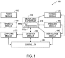
- Fig. 1 shows a block diagram of an exemplary DNA analyzer 100 according to an embodiment of the disclosure.
- the DNA analyzer 100 includes a microfluidic chip module 110, a thermal module 120, a pressure module 130, a high voltage module 140, a detection module 150, a power module 160, a computing module 170, and a controller module 180. Additionally, the DNA analyzer 100 can include a magnetic module 190. These elements can be coupled together as shown in Fig. 1 .
- the DNA analyzer 100 is capable of processing sample-to-answer DNA analysis on an integrated single-chip. Thus, using the DNA analyzer 100 to perform DNA analysis does not need substantial experience and knowledge of DNA processes. In an example, the appropriate procedures to use the DNA analyzer 100 to perform DNA analysis can be learned in an hour. Additionally, the integrated single-chip DNA analysis requires a reduced volume of reagents, for example, in the order of a micro-liter. Further, the reduced volume of reagents can reduce thermal inputs for inducing thermal cycles in the DNA analysis, and thus reduce the time for DNA analysis.
- the microfluidic chip module 110 includes a microfluidic chip 111.
- the microfluidic chip 111 can be suitably coupled with other elements of the DNA analyzer 100 to perform integrated single-chip DNA analysis.
- the microfluidic chip module 110 is implemented as a disposable cartridge, and a cartridge interface that can couple the disposable cartridge with other components of the DNA analyzer 100 that are not included as part of the disposable cartridge.
- the disposable cartridge includes the microfluidic chip 111 and a micro-to-macro interface.
- the micro-to-macro interface couples the microfluidic chip 111 to macro structures on the disposable cartridge.
- the disposable cartridge can be separately stored, and can be installed in the DNA analyzer 100 at a time of DNA analysis. After the DNA analysis, the disposable cartridge can be suitably thrown away.
- the microfluidic chip 111 includes various domains that can be suitably configured to enable the integrated single-chip DNA analysis.
- DNA analysis generally includes a step of PCR amplification, and a step of electrophoretic separation.
- the microfluidic chip 111 can include a first domain 111a for the PCR amplification and a second domain 111b for the electrophoretic separation.
- the microfluidic chip 111 can include other domains that are suitably integrated with the first domain 111a and the second domain 111b.
- the microfluidic chip 111 includes a purification domain fluidically coupled with the first domain 111a.
- the purification domain can be used to extract and purify a template DNA. It is noted that any suitable techniques, such as solid-phase extraction, liquid-phase extraction, and the like, can be used to purify the template DNA in the purification domain.
- the microfluidic chip 111 includes a post-PCR clean-up/dilution domain that is fluidically coupled with the first domain 111a and the second domain 111b.
- the post-PCR clean-up/dilution domain can be used for any suitable process after the PCR amplification and before the electrophoretic separation.
- the first domain 111a includes a reservoir configured for PCR amplification.
- the first domain 111a includes multiple separated reservoirs to enable simultaneous PCR amplification for multiple DNA samples.
- the temperature at the first domain 111a can be controlled by the thermal module 120 to enable the PCR amplification.
- the PCR amplification on the microfluidic chip 111 requires only a small volume of reagents, and the PCR amplification can achieve rapid thermal cycling.
- the volume of reagents used for the PCR amplification can be in the order of sub-micro-liter, and the time required for the PCR amplification can be under 20 minutes.
- the second domain 111b can include a plurality of micro channels.
- the plurality of micro channels can be configured for electrophoretic separation. More specifically, each micro channel can be filled with, for example, polymer sieving matrix. Further, an electric field can be induced in the micro channel. Thus, when DNA fragments are injected in the micro channel, the DNA fragments can migrate by force of the electric field at different speeds based on the sizes of the DNA fragments.
- the second domain 111b can be configured to facilitate DNA fragments detection in the DNA analysis.
- DNA fragments are tagged with fluorescent labels during PCR, before being injected in the micro channels.
- the fluorescent labels can emit fluorescence of pre-known wavelength when excited by a laser beam.
- the second domain 111b includes a detection window configured for detection. The laser beam can be directed to pass through the detection window to excite the fluorescent labels in the micro channels. The emitted fluorescence can pass through the detection window to be collected and detected.
- the microfluidic chip 111 can include additional structures to facilitate the integrated single-chip DNA analysis.
- the microfluidic chip 111 can include microfluidic channels that can direct DNA fragments from the first domain 111a to the second domain 111b. Through the microfluidic channels, the DNA fragments flow in a solution from the first domain 111a to the second domain 111b.
- the microfluidic chip 111 can include inlets for receiving reagents and the template DNA.
- the microfluidic chip 111 can also include additional reservoirs for additional processing steps, such as dilution, cleanup, and the like.
- the microfluidic chip 111 can be constructed from any suitable material.
- the microfluidic chip 111 is constructed from glass.
- the microfluidic chip 1 1 1 is constructed from plastic or polymeric material.
- the disposable cartridge can include a sample acceptor and a reagent carrier.
- the sample acceptor accepts a swab used for taking DNA sample, such as from saliva, bloodstains, cigarettes, and the like. Further, the sample acceptor extracts a template DNA from the swab.
- the sample acceptor can use any suitable mechanism, such as solid-phase extraction, liquid-phase extraction, and the like to obtain and/or purify the template DNA from the swab.
- the sample acceptor uses a solid-phase DNA extraction method, such as silica beads based DNA extraction.
- the sample acceptor uses a liquid-phase DNA extraction method.
- the liquid-phase DNA extraction method can simplify the purification and extraction process, and reduce a total cost of the DNA analyzer 100.
- the sample acceptor uses an enzymatic DNA-isolation method to extract and purify the template DNA.
- the enzymatic DNA-isolation method can achieve liquid phase purification without a need of centrifugation.
- the sample acceptor can be suitably designed to maintain sample integrity.
- the sample acceptor can include a plurality of separated wells for taking swabs, for example.
- the DNA analysis can simultaneously process multiple DNA samples.
- Each well includes a liquid phase mixture that is sealed by a membrane at a bottom portion of the well.
- the liquid phase mixture can conduct enzymatic digestion of all proteins and other cellular interferences, with the exception of DNA.
- the liquid phase mixture can include thermostable proteinases from thermophilic Bacillus species.
- a liquid phase mixture including the thermostable proteinases from thermophilic Bacillus species is disclosed in U.S. Patent Application Publication No. 2004/0197788 , which is incorporated herein by reference in its entirety.
- the liquid phase mixture can perform DNA extraction and purification when a swab is immersed in the liquid phase mixture.
- the liquid phase method can achieve comparable DNA quality to other methodologies in both DNA concentration and purity.
- a final DNA concentration by the liquid phase method is in a range of 0.5-2 ng/ ⁇ L.
- liquid phase extraction method instead of the silica solid phase method can reduce the overall hydraulic pressure requirement to induce solution flow through the microfluidic chip 111.
- the liquid phase extraction can enable a valveless design for the microfluidic chip 111.
- the liquid phase extraction can simplify the DNA analyzer 100 and simplify the manufacturing and testing steps in association with the solid-phase extraction.
- a swab Before taking DNA sample, a swab can be sealed in a hard case to avoid contamination.
- the swab can be attached to a seal cap that can seal the hard case.
- the swab can be identified by various mechanisms.
- a barcode label is attached to the hard case to identify the swab.
- the seal cap has a radio frequency identification (RFID) tag implanted. The RFID tag can identify the swab attached to the seal cap throughout the process.
- RFID tag radio frequency identification
- the seal cap is a stepped seal cap that can seal the well in a first step, and a second step.
- the seal cap seals the well in the first step, the swab does not puncture the membrane.
- the seal cap seals the well in the second step, the swab punctures the membrane and is immersed in the liquid phase mixture. The liquid phase mixture can then extract template DNA from the swab.
- the reagent carrier can house a plurality of reagents for DNA analysis, such as reagents for polymerase chain reaction (PCR) amplification, solutions for electrophoretic separation, and the like.
- the reagent carrier houses reagents for multiplexed STR amplification.
- the reagents can perform multiplexed STR amplification and can use multiple fluorescent dyes to label STR alleles.
- the reagents can be commercially available reagent kits or can be tailored to the micro-scale chip environment to further facilitate the integrated single-chip DNA analysis.
- the reagent carrier houses solutions that are suitable for electrophoretic separation in the micro-scale chip environment.
- the reagent carrier houses a coating solution, such as poly-N-hydroxyethylacrylamide, and the like.
- the coating solution can be used to coat micro channel walls prior to the separation to reduce electro osmotic flow and enable single base pair resolution of amplified DNA fragments.
- the reagent carrier houses a dilution solution, such as water and/or Formamide, and the like.
- the dilution solution can be used to reduce the ionic strength of the sample in order to promote better electro-kinetic injection.
- the reagent carrier houses an internal lane standard (ILS).
- ILS internal lane standard
- the reagent carrier also houses a polymer solution for electrophoretic separation in the micro-scale chip environment.
- the polymer solution is used as gels to provide a physical separation of DNA fragments according to chain length.
- the polymer solution can include a sieving or non-sieving matrix.
- polymer solutions including a sieving or non-sieving matrix are disclosed in U.S. Patents No. 7,531,073 , No. 7,399,396 , No. 7,371,533 , No. 7,026,414 , No. 6,811,977 and No. 6,455,682 , which are incorporated herein by reference in their entirety.
- a polymer sieving matrix can be used to yield a single-base resolution in a total separation length of 8 cm and in less than 400 seconds.
- the thermal module 120 receives control signals from the controller module 180, and induces suitable temperatures for DNA analysis, such as a temperature for DNA extraction, thermal cycles for the PCR amplification, a temperature for electrophoretic separation, and the like.
- the thermal module 120 includes a resistance heater to control a temperature in the wells of the sample acceptor for the DNA extraction and purification.
- the thermal module 120 includes another resistance heater to control a temperature at the second domain 111b.
- the thermal module 120 includes a heating unit, a cooling unit and a sensing unit to induce the thermal cycles for the PCR amplification at the first domain 111a.
- the heating unit can direct heat to the first domain 111a
- the cooling unit can disperse heat from the first domain 111a
- the sensing unit can measure a temperature at the first domain 111a.
- the controller module 180 can control the heating unit and the cooling unit based on the temperature measured by the sensing unit.
- the thermal module 120 performs non-contact thermal controls.
- the thermal module 120 includes an infrared light source as the heating unit, a cooling fan as the cooling unit, and an infrared pyrometer as the temperature sensing unit.
- the infrared light source such as a halogen light bulb, can excite, for example, the 1.3 ⁇ m vibrational band of liquid.
- the infrared light source can heat a small volume of solution within a reservoir in the first domain 111a independent of the reservoir to achieve rapid heating and cooling.
- the infrared pyrometer measures blackbody radiation from an outside of the reservoir.
- the reservoir is designed to have a thinner side for the infrared pyrometer measurements.
- the infrared pyrometer measurements at the thinner side can more accurately reflect the temperature of solution within the reservoir.
- the DNA analyzer 100 can achieve a precise temperature control along with rapid thermal cycles.
- the DNA analyzer 100 can achieve a temperature fluctuation of less than ⁇ 0.1°C, and a time of the thermal cycles for the PCR amplification can be less than 20 minutes.
- the pressure module 130 receives control signals from the controller module 180, and applies suitable pressures to the microfluidic chip module 110 to enable fluid movement.
- the pressure module 130 receives a sensing signal that is indicative of a pressure applied to the microfluidic chip module 110, and suitably adjusts its operation to maintain the suitable pressure to the microfluidic chip module 110.
- the pressure module 130 can include a plurality of pumps.
- the plurality of pumps control the injection of the various reagents and the template DNA solutions into the microfluidic chip 111.
- the plurality of pumps can be individually controlled to achieve any possible timing sequence.
- the pressure module 130 may include other pressure components to suit the integrated single-chip integrated DNA analysis.
- the microfluidic chip 111 has membrane valves.
- the pressure module 130 can include a hydrodynamic pressure/vacuum system to suitably control the closing and opening of the membrane valves to enable fluid movement through the microfluidic chip 111.
- the microfluidic chip 111 is valveless.
- the DNA analyzer 100 uses a liquid phase DNA extraction instead of a silica solid phase DNA extraction.
- the liquid phase DNA extraction can be integrated with following DNA processes on a valveless microfluidic chip.
- the pressure module 130 can be simplified to reduce the footprint, the weight, the cost, and the complexity of the DNA analyzer 100.
- the power module 160 receives a main power, and generates various operation powers for various components of the DNA analyzer 100.
- the DNA analyzer 100 is implemented using a modular design. Each module of the DNA analyzer 100 needs an operation power supply, which can be different from other modules.
- the power module 160 receives an AC power input, such as 100-240 V, 50-60 Hz, single phase AC power from a power outlet. Then, the power module 160 generates 5 V, 12 V, 24 V, and the like, to provide operation powers for the various components of the DNA analyzer 100.
- the power module 160 generates high voltages, such as 1000 V, 2000 V, and the like, for suitable DNA processes on the microfluidic chip 111, such as electro-kinetic injection, electrophoretic separation, and the like.
- the power module 160 can implement various protection techniques, such as power outrage protection, graceful shut-down, and the like, to protect the various components and data against power failure. It is noted that the power module 160 may include a back-up power, such as a battery module, to support, for example, graceful shut-down.
- a back-up power such as a battery module
- the high voltage module 140 can receive the high voltages from the power module 160 and suitably apply the high voltages on the microfluidic chip 111.
- the high voltage module 140 includes interfaces that apply the high voltages to suitable electrodes on the microfluidic chip 111 to induce electro-kinetic injection and/or electrophoretic separation.
- the detection module 150 includes components configured to suit the integrated single-chip DNA analysis. In an embodiment, the detection module 150 is configured for multicolor fluorescence detection.
- the detection module 150 includes a laser source unit, a set of optics and a detector unit.
- the laser source unit emits a laser beam.
- the laser source unit includes an argon-ion laser unit.
- the laser source unit includes a solid state laser, such as a coherent sapphire optically pumped semiconductor laser unit.
- the solid state laser has the advantages of reduced size, weight and power consumption.
- the set of optics can direct the laser beam to pass through the detection window at the second domain 111b of the microfluidic chip 111.
- the laser beam can excite fluorescent labels attached to DNA fragments to emit fluorescence.
- the set of optics can collect and direct the emitted fluorescence to the detector unit for detection.
- STR alleles are separated in the second domain 111b according to sizes. STR alleles of different sizes pass the detection window at different times.
- STR alleles of overlapping sizes can be tagged with fluorescent labels of different colors.
- the detector unit can be configured to detect an STR allele having a fluorescent label based on a time of fluorescence emitted by the fluorescent label and a color of the emitted fluorescence.
- ILS internal lane standard
- the ILS includes DNA fragments of known sizes, and can be tagged with a pre-determined fluorescent dye.
- the detector unit detects fluorescence emitted from the ILS to set up a size scale.
- the detector unit detects fluorescence emitted from the STR alleles.
- the detector unit can suitably convert the detected fluorescence into electrical signals.
- the electrical signals can be suitably stored and/or analyzed.
- a processor executes DNA analysis software instructions to identify the STR alleles by their sizes and emitted fluorescence colors (wavelengths).
- the computing module 170 includes computing and communication units.
- the computing module 170 includes a personal computer.
- the personal computer can be coupled with the controller module 180 to provide a user interface.
- the user interface can inform the status of the DNA analyzer 100, and can receive user instructions for controlling the operation of the DNA analyzer 100.
- the personal computer includes various storage media to store software instruction and data.
- the personal computer can include DNA analysis software that can perform data processing based on raw data obtained from the detection module 150.
- the personal computer can be coupled to external processing units, such as a database, a server, and the like to further process the data obtained from the DNA analyzer 100.
- the magnetic module 190 can enable a magnetic solid phase for the integrated single chip DNA analysis.
- the magnetic solid phase can be suitably incorporated in the integrated single chip DNA analysis to facilitate a volume reduction to suit for low copy numbers of template DNAs.
- the magnetic solid phase can be suitably incorporated into an integrated single chip sequencing DNA analysis.
- the controller module 180 can receive status signals and feedback signals from the various components, and provide control signals to the various components according to a control procedure. In addition, the controller module 180 can provide the status signals to, for example, the personal computer, to inform the user. Further, the controller module 180 can receive user instructions from the personal computer, and may provide the control signals to the various components based on the user instructions.
- the controller module 180 receives user instructions from the personal computer to perform a STR typing analysis, for example.
- the controller module 180 then monitors the microfluidic chip module 110 to check whether a suitable disposable cartridge has been installed, and whether swabs have been identified and suitably immersed in the liquid phase mixture to extract template DNA.
- the controller module 180 confirms the proper status at the microfluidic chip module 110, the controller module 180 starts a control procedure corresponding to the STR typing analysis.
- the controller module 180 can control the thermal module 120 to maintain an appropriate temperature at the wells of the sample acceptor for a predetermined time.
- the liquid phase mixture in the wells can extract template DNAs from the swabs.
- the controller module 180 can control the pressure module 130 to pump the extracted template DNAs into the first domain 111a of the microfluidic chip 111.
- the controller module 180 can control the pressure module 130 to pump reagents for multiplexed STR amplification into the first domain 111a.
- controller module 180 can control the thermal module 120 to induce thermal cycling for the multiplexed STR amplification at the first domain 111a.
- the reagents and the thermal cycling can cause DNA amplification.
- the DNA amplicons can be suitably tagged with fluorescent labels.
- the controller module 180 can control the pressure module 130 to flow the DNA amplicons to the second domain 111b.
- the controller module 180 may control the pressure module 130 to pump a dilution solution into the microfluidic chip 111 to mix with the DNA amplicons.
- the controller module 180 may control the pressure module 130 to pump an ILS into the microfluidic chip 111 to mix with the DNA amplicons.
- the controller module 180 controls the high voltage module 140 to induce electro-kinetic injection to inject DNA fragments into the micro channels.
- the DNA fragments include the amplified targets, and the ILS. Then, the controller module 180 controls the high voltage module 140 to induce electrophoretic separation in the micro channels. Additionally, the controller module 180 can control the thermal module 120 to maintain a suitable temperature at the second domain 111b during separation, for example, to maintain the temperature for denaturing separation of the DNA fragments.
- the controller module 180 then controls the detection module 150 to detect the labeled DNA fragments.
- the detection module 150 can emit and direct a laser beam to the micro channels to excite the fluorescent labels to emit fluorescence. Further, the detection module 150 can detect the emitted fluorescence and store detection data in a memory.
- the detection data can include a detection time, and a detected color (wavelength), along with a detected intensity, such as a relative magnitude of the detected fluorescence.
- the detection data can be transmitted to the personal computer for storage. Additionally, the controller module 180 can provide control statuses to the personal computer to inform the user. For example, the controller module 180 can send an analysis completed status to the personal computer when the control procedure is completed.
- the DNA analyzer 100 can be suitably configured for various DNA analyses by suitably adjusting the reagents housed by the reagent carrier and the control procedure executed by the controller module 180.
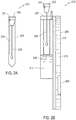
- Fig. 2A shows a swab storage example 212
- Figs. 2B-2C show a side elevation view and a front elevation view of a sample cartridge example 215 according to an embodiment of the disclosure
- the swab storage 212 includes a case 203, a seal cap 202 and a swab 205.
- the seal cap 202 and the swab 205 are attached together.
- the swab storage 212 includes an identifier, such as a barcode label 204 that can be attached to the case 203, an RFID tag 201 that can be implanted in the seal cap 202, and the like.
- the swab 205 Before taking DNA sample, the swab 205 is safely stored in the case 203 to avoid contamination. After taking DNA sample, the swab 205 can be placed in the sample cartridge 215.
- the sample cartridge 215 can include a microfluidic chip 211, a sample acceptor 207 and a reagent carrier 206.
- the sample acceptor 207 includes a plurality of separated wells 207A-207D for taking swabs.
- Each well includes a liquid phase mixture 214 that is sealed by a membrane 208 at a bottom portion of the well.
- the liquid phase mixture 214 can conduct enzymatic digestion of all proteins and other cellular interferences, with the exception of DNA, and thus can perform DNA extraction and purification when a swab with DNA sample is inserted in the liquid phase mixture 214.
- sample cartridge 215 is described in the context of swabs, it should be understood that the sample cartridge 215 can be suitably adjusted to suit other DNA gathering methods, such as blood stain cards, airborne samples, fingerprints samples, and the like.
- the seal cap 202 is a stepped seal cap that can seal the well in a first step, and a second step.
- the seal cap 202 seals the well in the first step, the swab 205 does not puncture the membrane 208, and can be safely sealed in the well to maintain sample integrity.
- the seal cap 202 seals the well in the second step, the swab 205 punctures the membrane 208 and is immersed in the liquid phase mixture 214.
- the reagent carrier 206 houses various solutions for DNA analysis.
- the reagent carrier houses reagents for multiplexed STR amplification.
- the reagent carrier houses a coating solution, such as poly-N-hydroxyethylacrylamide, and the like. The coating solution can be used to coat micro channel walls prior to the separation.
- the reagent carrier houses a dilution solution, such as water, formamide, and the like. The dilution solution can be used to reduce the ionic strength in order to promote better electro-kinetic injection.
- the reagent carrier houses an internal lane standard (ILS). The ILS can be used for size measurement.
- the reagent carrier also houses a polymer solution for electrophoretic separation in the micro-scale chip environment.
- a new disposable cartridge 215 is taken from a storage package, and installed in a DNA analyzer, such as the DNA analyzer 100. Then, a swab 205 can be used to take a DNA sample. The swab 205 is then identified and inserted into one of the wells 207A-207D and sealed in the first step. Additional swabs 205 can be used to take DNA samples, and then identified and inserted into the un-used wells 207A-207D.
- the DNA analyzer 100 can include a mechanism that can push the seal caps 202 to seal the wells 207A-207D in the second step, thus the swabs 205 can puncture the membrane 208, and immerse in the liquid phase mixture 214.
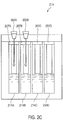
- Fig. 3 shows a schematic diagram of a microfluidic chip example 311 according to an embodiment of the disclosure.
- the microfluidic chip 311 includes various micro structures, such as inlets 312-314, reaction reservoirs 315-316, channels 317a-317b, electrode reservoirs 318, outlets (not shown), and the like, that are integrated for single-chip DNA analysis. It is noted that the various micro structures can be designed and integrated to suit for various DNA analyses, such as STR typing, sequencing, and the like.
- the inlets 312-314 can be coupled to a pressure module to inject solutions in the microfluidic chip 311. As described above, the connection can be made via a micro-macro interface.
- the inlet 312 is for injecting a template DNA solution from a well of the sample acceptor 207
- the inlet 313 is for injecting PCR reagents from the reagent carrier 206.
- the inlet 313 can be used for injecting dilution solution and ILS from the reagent carrier 206.
- the reaction reservoirs 315-316 are configured for various purposes.
- the reaction reservoir 315 is configured for the PCR amplification
- the reaction reservoir 316 is configured for the post-PCR processes, such as dilution, and the like.
- the reaction reservoir 315 is located in a first domain 311a, which is a thermal control domain.
- the temperature within the thermal control domain 311a can be precisely controlled.
- an infrared heating unit directs heat to the thermal control domain 311a
- a cooling fan disperses heat from the thermal control domain 311a
- an infrared sensing unit measures a temperature in the thermal control domain 311a.
- the infrared heating unit and the cooling fan can be controlled based on the temperature measured by the infrared sensing unit.
- the infrared heating unit, the cooling fan, and the infrared sensing unit can perform thermal control without contacting the thermal control domain 311a.
- the temperature in the thermal control domain 311a is measured by a thermal coupling technique.
- the microfluidic chip 311 includes a thermal-coupler reservoir 319 within the first domain 311a.
- the solution temperature within the thermal-coupler reservoir 319 can be measured by any suitable technique. Based on the measured solution temperature within the thermal-coupler reservoir 319, the solution temperature within the reaction reservoir 315 can be determined. Then, the infrared heating unit and the cooling fan can be controlled based on the temperature measured by the thermal coupling technique in order to control the solution temperature in the reaction reservoir 315.
- the PCR mixture is fluidically directed from the reaction reservoir 315 to a post-PCR clean-up/dilution domain, such as the reaction reservoir 316.
- the reaction reservoir 316 the PCR mixture is diluted.
- the PCR mixture and a dilutant solution are mixed together according to a ratio from 1:5 to 1:20 (1 part of PCR mixture to 5-20 parts of dilutant).
- ILS can be added in the reaction reservoir 316 to mix with the PCR mixture.
- the channels 317a-317b are located in a second domain 311b. Electric fields can be suitably applied onto the channels 317a-317b.
- the channels 317a-317b are configured according to a cross-T design, having a short channel 317a and a long channel 317b.
- the electrode reservoirs 318 can be used to apply suitable electric fields over the short channel 317a and the long channel 317b.
- the short channel 317a is configured for electro-kinetic injection
- the long channel 317b is configured for electrophoretic separation.
- DNA fragments can be injected from the reaction reservoir 316 into the short channel 317a at the intersection of the short channel 317a and the long channel 317b.
- the long channel 317b can be filed with sieving matrix.
- the injected DNA fragments can migrate in the long channel 317b to the positive side of the electric field induced by the high voltage, in the presence of the sieving matrix.
- the length of the long channel 317b is about 8.8 cm with detection at about 8 cm from the intersection.
- the microfluidic chip 311 can include other structures to assist DNA analysis.
- the microfluidic chip 311 includes an alignment mark 321.
- the alignment mark 321 can assist a detection module to align to the long channel 317b.
- the inlet 312 can input a template DNA into the reaction reservoir 315, and the inlet 313 can input PCR reagents into the reaction reservoir 315. Then, thermal-cycling can be induced at the first domain 311a, and PCR amplification can be conducted in the reaction reservoir 315 to amplify DNA fragments based on the template DNA and the PCR reagents. After the PCR amplification, the DNA amplicons in the reaction reservoir 315 can be mobilized into the reaction reservoir 316 in a liquid flow. In the reaction reservoir 316, a dilution solution and ILS can be input to mix with the DNA fragments.
- the DNA fragments in the reaction reservoir 316 can be injected across the short channel 317a by electro-kinetic injection.
- the DNA fragments then migrate in the long channel 317b under the force of electric field applied over the long channel 317b.
- the speed of migration depends on the sizes of the DNA amplicons, in the presence of the sieving matrix.
- the DNA fragments are separated in the long channel 317b according to their sizes.
- Fig. 4 shows an exemplary DNA analyzer 400 according to an embodiment of the disclosure.
- the DNA analyzer 400 is packaged in a box.
- the box includes handles, wheels and the like, to facilitate transportation of the DNA analyzer 400.
- the total weight of the DNA analyzer 400 is less than 70 lb, and is appropriate for two persons to carry.
- the DNA analyzer 400 is implemented in a modular manner.
- Each module can be individually packaged, and can include an interface for inter-module couplings. Thus, each module can be easily removed and replaced.
- the modular design can facilitate assembly, troubleshooting, repair, and the like.
- the DNA analyzer 400 includes a user module (UM) 410, an active pressure module (APM) 430, a detection module 450, a power module (PM) 460, a computing module 470, and a controller module (CM) 480.
- the DNA analyzer 400 includes a sample cartridge storage 415 and a swab storage 412.
- the UM 410 includes a holder to hold a sample cartridge, such as the sample cartridge 215, at an appropriate position when the sample cartridge is inserted by a user. Further, the UM 410 includes interface components to couple the sample cartridge 215 with, for example, the APM 430, the detection module 450, and the like.
- the UM 410 includes thermal components, such as resistance heaters 421, a cooling fan 422, an infrared heating unit 423, and the like. The thermal components can be suitably positioned corresponding to the sample cartridge 215. For example, a resistance heater 421 is situated at a position that can effectively control a temperature of the liquid phase mixture within the plurality of separated wells on the sample cartridge 215.
- the temperature can be determined to optimize enzyme activities of the liquid phase mixture to conduct enzymatic digestion of all proteins and other cellular interferences, with the exception of DNA.
- Another resistance heater 421 is at a position that can effectively control a temperature of the separation channel on the microfluidic chip 211.
- the infrared heating unit is at a position that can direct heat to the thermal control domain of the microfluidic chip 211 on the sample cartridge 215.
- the cooling fan is at a position that can effectively disperse heat from the thermal control domain.
- the UM 410 includes a high voltage module that can apply suitable high voltages via the electrode reservoirs of the microfluidic chip 211.
- the UM 410 can include other suitable components.
- the UM 410 includes a magnetic module that can suitably apply magnetic control over a domain of the microfluidic chip 211.
- the APM 430 includes suitably components, such as pumps, vacuums, and the like, to apply suitable pressures to the microfluidic chip 211 to enable fluid movement.
- the PM 460 receives an input main power, and generates various operation powers, such as 6 V, 12 V, 24 V, 1000V, 2000V, and the like, for various components of the DNA analyzer 400.
- the detection module 450 can include a laser module (LM) 451, a passive optics module (POM) 452, and an active optics module (AOM) 453.
- the LM 451 can include any suitable device to emit a laser beam.
- the LM 451 includes an argon-ion laser.
- the LM 451 includes a diode laser.
- the LM 451 includes a solid state laser, such as a coherent sapphire optically pumped semiconductor laser.
- the solid state laser can have a reduced size and weight, and can consume less power than the argon-ion laser.
- the solid state laser generates less waste heat, such that fan size can be reduced to reduce footprint of the DNA analyzer 400.
- the AOM 453 includes optical elements that may need to be adjusted with regard to each inserted microfluidic chip.
- the AOM 453 includes a plurality of optical fibers that are respectively coupled to a plurality of separation channels on the microfluidic chip.
- the plurality of optical fibers can respectively provide laser beams to the plurality of separation channels to excite fluorescence emission.
- the plurality of optical fibers can return the emitted fluorescence from the plurality of separation channels.
- the POM 452 includes various optical elements, such as lens, splitters, photo-detectors, and the like, that do not need to be adjusted with regard to each inserted microfluidic chip.
- the POM 452 is calibrated and adjusted with regard to the LM 451 and the AOM 453 when the detection module 450 is assembled. Then, the optical elements within the POM 452 are situated at relatively fixed positions, and do not need to be adjusted with regard to each inserted microfluidic chip.
- the controller module 480 is coupled to the various components of the DNA analyzer 400 to provide control signals for DNA analysis.
- the controller module 480 includes a control procedure that determines sequences and timings of the control signals.
- the computing module 470 is implemented as a personal computer.
- the personal computer includes a processor, a memory storing suitable software, a keyboard, a display, and a communication interface.
- the computing module 470 can provide a user interface to ease user control and monitor of the DNA analysis by the DNA analyzer 400.
- Fig. 5 shows a flow chart outlining a process example for using a DNA analyzer, such as the DNA analyzer 400, to perform DNA analysis according to an embodiment of the disclosure. The process starts at S501, and proceeds to S510.
- a user of the DNA analyzer 400 plugs in a main power supply.
- the main power supply can be a 110 V, 50 Hz, AC power supply, or can be a 220V, 60 Hz, AC power supply.
- the power module 460 can convert the main power supply to a plurality of operation powers, and provide the plurality of operation powers to the various modules of the DNA analyzer 400. Then, the process proceeds to S515.
- the user starts up a user control interface.
- the user turns on the personal computer 470, and starts a software package that interacts with the user and the controller module 480.
- the software package enables the personal computer 470 to provide a user control interface on the display. Further, the software package enables the personal computer 470 to receive user instructions via the keyboard or mouse.
- the software packages can also enable the personal computer 470 to communicate with the controller module 480. Then, the process proceeds to S520.
- the user instructs the DNA analyzer 400 to initialize.
- the user control interface receives the initialization instruction, and the software package enables the personal computer 470 to send the initialization instruction to the controller module 480.
- the controller module 480 can then initialize the various components of the DNA analyzer 400. For example, the controller module 480 can power on the various components, check the status and reset the status if needed. Then, the process proceeds to S525.
- the user inserts a sample cartridge 215 in the UM 410.
- the sample cartridge 215 can be positioned by a holder.
- the interface components can suitably couple the sample cartridge 215 to other components of the DNA analyzer 400. Then, the process proceeds to S530.
- the user takes a swab 205, and lets the DNA analyzer 400 to identify the swab 205.
- the DNA analyzer 400 includes a barcode reader that can read the barcode label 204 attached to the case 203 for storing the swab 205.
- the DNA analyzer 400 excites the RFID 201 implanted in the seal cap 202 of the swab 205 to obtain a unique serial number of the swab 205. Then, the process proceeds to S535.
- the user uses the swab 205 to take a DNA sample and inserts the swab 205 into a well of the sample cartridge 215.
- the user may repeat the steps S530 and S535 to insert multiple swabs 205 into the separated wells of the sample cartridge 215. Then, the process proceeds to S540.
- the user instructs the DNA analyzer 400 to start a DNA analysis.
- the user control interface receives the start instruction, and the software package enables the personal computer 470 to send the start instruction to the controller module 480.
- the controller module 480 can start a control procedure corresponding to the DNA analysis.
- the controller module 480 starts an STR typing procedure corresponding to a multiplexed STR typing analysis.
- the controller module 480 starts a sequencing procedure corresponding to DNA sequencing analysis. Then, the process proceeds to S545.
- the user waits and monitors the status of the DNA analysis.
- the control procedure can specify sequences and timings of control signals to various components of the DNA analyzer 400 corresponding to the DNA analysis.
- the controller module 480 automatically sends the control signals according to the sequences and the timings specified in the control procedure.
- the controller module 480 receives status and feedback signals from the various components, and sends them to the personal computer 470.
- the personal computer 470 then provides the analysis status for the user to monitor. Then, the process proceeds to S550.
- the controller module 480 finishes executing the control procedure, and sends an analysis-completed status to the personal computer 470.
- the personal computer 470 can inform the user of the analysis-completed status via the user control interface. Then, the process proceeds to S555.
- the user performs post data processing.
- the user can store the raw data of the DNA analysis, or transmit the raw data to a remote receiver.
- the user may start a software package for post data processing.
- the software package for post data processing can be suitably integrated with the control procedure.
- the software package for post data processing is executed automatically to perform post data processing. The process then proceeds to S599 and terminates.
- the user may throw away the sample cartridge and repeat S520-S550. It is also noted that the sequence of the DNA analysis steps can be suitably adjusted. For example, S535 and S530 can be swapped, thus a swab can be first used to take a DNA sample, and then identified by the DNA analyzer 400.
- Fig. 6 shows a flow chart outlining a process example 600 for a DNA analyzer to perform multiplexed STR typing according to an embodiment of the disclosure. The process starts at S601 and proceeds to S610.
- the controller module 480 controls the resistance heater 421 to maintain a temperature for template DNA extraction and purification. More specifically, the resistance heater 421 is positioned corresponding to the plurality of wells on the sample cartridge 215.
- a well can accept a swab 205.
- the swab 205 can puncture the membrane that seals the liquid phase mixture at the bottom of the well, thus the swab 205 is immersed into the liquid phase mixture.
- the liquid phase mixture can extract and purify a template DNA from the swab at the temperature according to enzymatic DNA isolation method.
- the liquid phase mixture can achieve a compatible DNA concentration and purity to silica based solid phase extraction method in about 6 minutes. Then, the process proceeds to S620.
- the controller module 480 controls the APM 430 to flow the extracted template DNA and reagents to a reaction reservoir for the PCR amplification.
- the reagent carrier 206 houses reagents for multiplexed STR amplification.
- the controller module 480 sends control signals to the APM 430.
- a pump pumps the liquid phase mixture from the well to the reaction reservoir, and another pump pumps the reagents from the reagent carrier 206 to the reaction reservoir. Then, the process proceeds to S630.
- the controller module 480 controls the cooling fan 422 and the infrared heating unit 423 to induce thermal cycling in the reaction reservoir for the multiplexed STR amplification.
- the reagents can attach fluorescent labels to the DNA amplicons during the STR amplification process. The process then proceeds to S640.
- the solution can be diluted. More specifically, the controller module 480 sends control signals to the APM 430 after the PCR amplification. In response to the control signals, the APM 430 flows the DNA amplicons into a dilution reservoir. In addition, the APM 430 flows a dilution solution from the reagent carrier into the dilution reservoir. The process then proceeds to S650.
- the controller module 480 sends control signals to the high voltage module in the UM 410 to inject the DNA amplicons across the injection arm (the short channel 317a). Then, the process proceeds to S660.
- the controller module 480 sends control signals to the high voltage module in the UM 410 to apply appropriate high voltage over the separation channel (the long channel 317b) to separate the DNA amplicons based on sizes. The process then proceeds to S670.
- the controller module 480 sends control signals to the detection module 450 to excite the fluorescent labels to emit fluorescence and detect the emitted fluorescence.
- the raw detection data can be sent to the personal computer 470 for storage and post-processing. The process then proceeds to S699, and terminates.
- step S660 and the step S670 can be executed in parallel.
- the controller module 480 sends control signals to both the high voltage module in the UM 410 and the detection module 450 at about the same time.
- the control signals to the high voltage module in the UM 410 cause the electrophoretic separation in the separation channel, while the control signals to the detection module 450 cause fluorescence detection.
- process 600 can be suitably adjusted along with reagents adjustments for other DNA analysis, such as qPCR DNA quantitation, sequencing, and the like.
- step S601 to S630 are executed, and step S640 to S670 can be deleted.
- the controller module 480 sends control signals to the detection module 450 to detect florescence emitted by the fluorescent labels in the qPCR reservoir.
- a magnetic solid phase purification process step can be suitably added into the process 600 to facilitate further volume reduction, thus the process 600 can be adjusted for DNA sequencing.
- Fig. 7 shows a plot of thermal cycling for polymerase chain reaction (PCR) amplification induced in two systems.
- Thermal cycling 710 is induced in a first system
- thermal cycling 720 is induced in a second system.
- Each of the thermal cycling 710 and the thermal cycling 720 is induced by an infrared light source and a cooling fan based on a temperature measurement using a thermal-coupler reservoir technique. Both systems achieve a temperature fluctuation of less than ⁇ 0.1°C. In addition, a system-to-system reproducibility is achieved.
- Fig. 8 shows a plot 800 of a 16-loci STR typing analysis result obtained from an implemented DNA analyzer according to an embodiment of the disclosure.
- the DNA analyzer accepts a sample, such as in the form of a swab, extracts a template DNA from the sample, and acts on a microfluidic chip to perform an integrated single-chip DNA analysis based on the extracted template DNA. More specifically, the DNA analyzer pumps the extracted template DNA and 16-loci STR reagents in a reservoir within a first domain of the microfluidic chip. Then, the DNA analyzer induces thermal cycling in the first domain of the microfluidic chip to perform multiplexed 16-loci PCR amplification based on the template DNA.
- the 16-loci STR reagents use four fluorescent labels having different wavelengths to label the DNA fragments.
- the DNA analyzer pumps ILS into the amplified STR alleles.
- the ILS is labeled with a fifth fluorescent label having a different wavelength from the four fluorescent labels used by the 16-loci STR reagents.
- the DNA analyzer injects the STR alleles along with the ILS into a second domain of the microfluidic chip.
- the second domain includes a separation channel.
- the DNA analyzer induces an electrical field over the separation channel for electrophoretic separation. Under the electrical field, the STR alleles and the ILS migrate in the separation channel based on sizes.
- the DNA analyzer then generates and directs a laser beam to the separation channel to excite the fluorescent labels to emit fluorescence. Further, the emitted fluorescence is collected and detected by the DNA analyzer.
- the DNA analyzer detects fluorescence intensities of different wavelengths over time, and identifies an STR in the sample based on a combination of wavelength and size comparison with ILS.
- the plot 800 shows five curves 810-850.
- the curve 810 shows detected fluorescence intensity versus time for a first wavelength.
- the curve 820 shows detected fluorescence intensity versus time for a second wavelength.
- the curve 830 shows detected fluorescence intensity versus time for a third wavelength.
- the curve 840 shows detected fluorescence intensity versus time for a fourth wavelength, and the curve 850 shows detected fluorescence intensity versus time for a fifth wavelength.
- the fifth wavelength corresponds to the fluorescent label used to tag the ILS, thus spikes in the curve 850 are of known sizes.
- Spikes in the curves 810-840 correspond to STR alleles in the sample under analysis.
- the sizes of the STR alleles can be determined based on comparison to the spikes in the curve 850.
- the STR alleles can be identified based on the wavelength and the size comparison with the ILS
Claims (23)
- Cartouche (215) caractérisée en ce qu'elle comprend :un accepteur d'échantillon (207) configuré pour extraire une matrice d'ADN ;une puce microfluidique (111, 211, 311) externe à l'accepteur d'échantillon (207), et ayant une entrée (312) configurée pour recevoir la matrice d'ADN extraite par l'accepteur d'échantillon (207) ;un premier domaine (111a, 311a) et un domaine de dilution (316) qui est couplé de manière fluidique au premier domaine (111a, 311a) et est configuré pour diluer un mélange de PCR reçu à partir du premier domaine (111a, 311a) avec un diluant ;un deuxième domaine (111b, 311b) qui est couplé de manière fluidique au domaine de dilution (316) de manière à recevoir les fragments d'ADN amplifiés, où le premier domaine (111a, 311a) est configuré pour effectuer une amplification par réaction en chaîne par polymérase (PCR) de fragments d'ADN sur la base de la matrice d'ADN, et le deuxième domaine (111b, 311b) a un canal de séparation (317) qui est configuré pour effectuer une séparation par électrophorèse des fragments d'ADN amplifiés.
- Cartouche (215) de la revendication 1, comprenant en outre : un support de réactifs (206) configuré pour tous les réactifs pour l'amplification par PCR, et les solutions pour la séparation par électrophorèse.
- Cartouche (215) de la revendication 1, dans laquelle l'accepteur d'échantillon est configuré pour extraire la matrice d'ADN par au moins l'une d'une extraction en phase solide de silice et d'une isolation enzymatique d'ADN en phase liquide.
- Cartouche (215) de la revendication 1, dans laquelle l'accepteur d'échantillon comprend : un puits (207A-207D) ayant un mélange en phase liquide (214) pour extraire la matrice d'ADN.
- Cartouche (215) de la revendication 4, dans laquelle le mélange en phase liquide (214) est scellé dans le puits (207A-207D) avant l'extraction.
- Analyseur d'ADN (100, 400) qui est configuré pour recevoir la cartouche (215) de la revendication 1 et agir sur la puce microfluidique (111, 211, 311) pour effectuer une analyse d'ADN.
- Analyseur d'ADN (100, 400), caractérisé en ce qu'il comprend :une cartouche (215) comprenant un accepteur d'échantillon (207) configuré pour extraire une matrice d'ADN, et une puce microfluidique (111, 211, 311);une interface pour coupler la puce microfluidique (111, 211, 311) à l'analyseur d'ADN (100, 400), où la puce microfluidique (111, 211, 311) comporteune entrée (312) configurée pour recevoir la matrice d'ADN extraite par l'accepteur d'échantillon (207) de la cartouche (215), l'accepteur d'échantillon (207) étant externe à la puce microfluidique (111, 211, 311) ;un premier domaine (111a, 311a) configuré pour une amplification par réaction en chaîne par polymérase (PCR) de fragments d'ADN, les fragments d'ADN étant marqués avec des marqueurs fluorescents ; etun domaine de dilution (316) qui est couplé de manière fluidique au premier domaine (111a, 311a) et est configuré pour diluer un mélange de PCR reçu à partir du premier domaine (111a, 311a) avec un diluant ;un deuxième domaine (111b, 311b) qui est couplé de manière fluidique au domaine de dilution (316) de manière à recevoir les fragments d'ADN amplifiés, le deuxième domaine (111b, 311b) comportant un canal de séparation (317) qui est configuré pour effectuer une séparation par électrophorèse des fragments d'ADN amplifiés ;un module de pression (130) configuré pour faire circuler un liquide dans la puce microfluidique (111, 211, 311) ;un module thermique (120) configuré pour induire des cycles thermiques au niveau du premier domaine (111a, 311a) de la puce microfluidique (111, 211, 311) pour l'amplification par PCR ;un module d'alimentation (160, 460) configuré pour générer des tensions à appliquer au deuxième domaine (111b, 311b) de la puce microfluidique (111, 211, 311) pour la séparation par électrophorèse ;un module de détection (150, 450) configuré pour exciter les marqueurs fluorescents afin d'émettre une fluorescence, et détecter la fluorescence émise ; etun module de commande (180, 480) configuré pour commander le module de pression (130), le module thermique (120), le module d'alimentation (160, 460) et le module de détection (150, 450) selon une procédure de commande pour agir sur la puce microfluidique (111, 211, 311) pour une analyse d'ADN monopuce.
- Analyseur d'ADN (100, 400) de la revendication 7, dans lequel le module de pression (130) comprend en outre : une pluralité de pompes configurées pour injecter une matrice d'ADN et des réactifs dans la puce microfluidique (111, 211, 311).
- Analyseur d'ADN (100, 400) de la revendication 8, dans lequel le module de commande (180, 480) est configuré pour commander respectivement la pluralité de pompes.
- Analyseur d'ADN (100, 400) de la revendication 7, dans lequel le module de pression (130) comprend en outre : une pompe à vide configurée pour commander une vanne à membrane sur la puce microfluidique (111, 211, 311).
- Analyseur d'ADN (100, 400) de la revendication 7, dans lequel le module thermique (120) comprend en outre :une unité de chauffage (423) configurée pour diriger la chaleur vers le premier domaine (111a, 311a) ;une unité de refroidissement configurée pour disperser la chaleur du premier domaine (111a, 311a) ; etune unité de détection configurée pour mesurer une température au niveau du premier domaine (111a, 311a).
- Analyseur d'ADN (100, 400) de la revendication 11, dans lequel l'unité de chauffage (423) comporte une source de lumière infrarouge pour chauffer le premier domaine (111a, 311a).
- Analyseur d'ADN (100, 400) de la revendication 11, dans lequel l'unité de détection comporte un pyromètre infrarouge pour mesurer la température.
- Analyseur d'ADN (100, 400) de la revendication 11, dans lequel l'unité de détection mesure une température dans un réservoir de coupleur thermique (319) dans le premier domaine (111a, 311a), le réservoir de coupleur thermique étant couplé thermiquement à un réservoir de réaction (315, 316) dans le premier domaine (111a, 311a) configuré pour l'amplification par PCR.
- Analyseur d'ADN (100, 400) de la revendication 7, dans lequel le module de détection (150, 450) comprend en outre :un module laser (451) configuré pour émettre un faisceau laser ;un module de détection (150, 450) configuré pour détecter une fluorescence ; etun ensemble d'éléments optiques pour diriger le faisceau laser vers le canal de séparation (317) afin d'exciter les marqueurs fluorescents pour émettre une fluorescence, et diriger la fluorescence excitée vers le module de détection (150, 450) pour la détection.
- Analyseur d'ADN (100, 400) de la revendication 7, comprenant en outre au moins l'un parmi :un lecteur de code à barres configuré pour lire un code à barres afin d'identifier un échantillon d'ADN ; etun lecteur d'identification par radiofréquence (RFID) configuré pour lire une étiquette RHD (201) pour identifier un échantillon d'ADN.
- Analyseur d'ADN (100, 400) de la revendication 7, comprenant en outre : un module magnétique (190) configuré pour commander des billes magnétiques utilisées dans une phase solide magnétique d'un procédé d'analyse d'ADN.
- Procédé d'analyse d'ADN comprenant le fait :de fournir une cartouche (215) comprenant un accepteur d'échantillon (207) configuré pour extraire une matrice d'ADN, et une puce microfluidique (111, 211, 311) externe à l'accepteur d'échantillon (207) et ayant une entrée (312),de recevoir, à travers l'entrée (312) de la puce microfluidique (111, 211, 311), une matrice d'ADN extraite de l'accepteur d'échantillon (207),d'induire des cycles thermiques dans un premier domaine (111a, 311a) de la puce microfluidique (111, 211, 311) pour l'amplification par PCR de fragments d'ADN ; le procédé comprenant en outre le fait :de diluer les fragments d'ADN amplifiés avec une solution de dilution ;d'induire un écoulement de liquide pour déplacer les fragments d'ADN amplifiés du premier domaine (111a, 311a) à un deuxième domaine (111b, 311b) de la puce microfluidique (111, 211, 311)ayant un canal de séparation (317) pour la séparation par électrophorèse ;d'effectuer une injection électrocinétique des fragments d'ADN dans le canal de séparation (317) ;d'induire un champ électrique sur le canal de séparation (317) pour séparer les fragments d'ADN par dimensions ; etde détecter les fragments d'ADN séparés.
- Procédé de la revendication 18, comprenant en outre le fait : de maintenir une température pour l'extraction d'ADN enzymatique afin d'extraire une matrice d'ADN.
- Procédé de la revendication 19, comprenant en outre le fait :d'injecter des réactifs dans un réservoir (315, 316) dans le premier domaine (111a, 311a) pour l'amplification par PCR ; etd'injecter la matrice d'ADN dans le réservoir (315, 316) pour l'amplification par PCR.
- Procédé de la revendication 18, comprenant en outre le fait : de maintenir une température dans le canal de séparation (317).
- Procédé de la revendication 18, dans lequel les fragments d'ADN amplifiés sont marqués avec des marqueurs fluorescents, et la détection des fragments d'ADN séparés comprend en outre le fait :d'émettre un faisceau laser ;de diriger le faisceau laser vers le canal de séparation (317) pour exciter les marqueurs fluorescents afin d'émettre une fluorescence ;de collecter la fluorescence émise ; etde renvoyer la fluorescence collectée pour la détection.
- Procédé de la revendication 18, comprenant en outre le fait : d'ajouter un standard interne « internai lane standard » (ILS) avec les fragments d'ADN amplifiés pour aider à une mesure de dimension.
Applications Claiming Priority (4)
| Application Number | Priority Date | Filing Date | Title |
|---|---|---|---|
| US21340409P | 2009-06-04 | 2009-06-04 | |
| US21340509P | 2009-06-04 | 2009-06-04 | |
| US21340609P | 2009-06-04 | 2009-06-04 | |
| PCT/US2010/026791 WO2010141139A1 (fr) | 2009-06-04 | 2010-03-10 | Puce microfluidique a echantillons multiples pour l'analyse d'adn |
Publications (2)
| Publication Number | Publication Date |
|---|---|
| EP2437889A1 EP2437889A1 (fr) | 2012-04-11 |
| EP2437889B1 true EP2437889B1 (fr) | 2018-08-08 |
Family
ID=42148393
Family Applications (3)
| Application Number | Title | Priority Date | Filing Date |
|---|---|---|---|
| EP10706884.3A Not-in-force EP2437887B1 (fr) | 2009-06-04 | 2010-03-02 | Puce microfluidique de plusieurs échantillon pour analyse de dna |
| EP10708482.4A Not-in-force EP2437888B1 (fr) | 2009-06-04 | 2010-03-10 | Apparail et procede de analyse optique pour la detection de dna par électrophorèse microfluidique |
| EP10708680.3A Not-in-force EP2437889B1 (fr) | 2009-06-04 | 2010-03-10 | Puce microfluidique de plusieurs échantillon pour analyse de dna |
Family Applications Before (2)
| Application Number | Title | Priority Date | Filing Date |
|---|---|---|---|
| EP10706884.3A Not-in-force EP2437887B1 (fr) | 2009-06-04 | 2010-03-02 | Puce microfluidique de plusieurs échantillon pour analyse de dna |
| EP10708482.4A Not-in-force EP2437888B1 (fr) | 2009-06-04 | 2010-03-10 | Apparail et procede de analyse optique pour la detection de dna par électrophorèse microfluidique |
Country Status (7)
| Country | Link |
|---|---|
| US (6) | US20110065101A1 (fr) |
| EP (3) | EP2437887B1 (fr) |
| AU (3) | AU2010257118B2 (fr) |
| CA (3) | CA2764678C (fr) |
| DE (3) | DE112010002222B4 (fr) |
| GB (3) | GB2483402B (fr) |
| WO (3) | WO2010141131A1 (fr) |
Cited By (1)
| Publication number | Priority date | Publication date | Assignee | Title |
|---|---|---|---|---|
| KR20210083784A (ko) * | 2019-12-27 | 2021-07-07 | 한국과학기술원 | 모듈형 미세 유체 장치 및 이를 이용한 유전자 증폭 방법 |
Families Citing this family (45)
| Publication number | Priority date | Publication date | Assignee | Title |
|---|---|---|---|---|
| JP2008513022A (ja) * | 2004-09-15 | 2008-05-01 | マイクロチップ バイオテクノロジーズ, インコーポレイテッド | マイクロ流体デバイス |
| GB0421529D0 (en) | 2004-09-28 | 2004-10-27 | Landegren Gene Technology Ab | Microfluidic structure |
| WO2008030631A2 (fr) | 2006-02-03 | 2008-03-13 | Microchip Biotechnologies, Inc. | Dispositifs microfluidiques |
| US9862984B2 (en) | 2006-04-21 | 2018-01-09 | Nanobiosym, Inc. | Single-molecule platform for drug discovery: methods and apparatuses for drug discovery, including discovery of anticancer and antiviral agents |
| KR20100028526A (ko) * | 2007-02-05 | 2010-03-12 | 마이크로칩 바이오테크놀로지스, 인크. | 마이크로유체 및 나노유체 장치, 시스템 및 응용 |
| US20090253181A1 (en) * | 2008-01-22 | 2009-10-08 | Microchip Biotechnologies, Inc. | Universal sample preparation system and use in an integrated analysis system |
| WO2010077322A1 (fr) * | 2008-12-31 | 2010-07-08 | Microchip Biotechnologies, Inc. | Instrument doté d'une puce microfluidique |
| ES2735514T3 (es) | 2009-02-03 | 2019-12-19 | Ande Corp | Purificación de ácido nucleico |
| WO2010141326A1 (fr) * | 2009-06-02 | 2010-12-09 | Integenx Inc. | Dispositif fluidique a soupapes a membrane |
| WO2010141131A1 (fr) | 2009-06-04 | 2010-12-09 | Lockheed Martin Corporation | Puce microfluidique a echantillons multiples pour l'analyse d'adn |
| EP3586945A3 (fr) | 2009-06-05 | 2020-03-04 | IntegenX Inc. | Système universel de préparation d'échantillons et utilisation dans un système d'analyse intégré |
| US8584703B2 (en) | 2009-12-01 | 2013-11-19 | Integenx Inc. | Device with diaphragm valve |
| US8512538B2 (en) | 2010-05-28 | 2013-08-20 | Integenx Inc. | Capillary electrophoresis device |
| US9121058B2 (en) | 2010-08-20 | 2015-09-01 | Integenx Inc. | Linear valve arrays |
| US8763642B2 (en) | 2010-08-20 | 2014-07-01 | Integenx Inc. | Microfluidic devices with mechanically-sealed diaphragm valves |
| AU2011315951B2 (en) | 2010-10-15 | 2015-03-19 | Lockheed Martin Corporation | Micro fluidic optic design |
| US9494496B2 (en) * | 2011-07-08 | 2016-11-15 | Hitachi High-Technologies Corporation | Solid-phase extraction apparatus and viscosity measurement apparatus |
| US20150136604A1 (en) | 2011-10-21 | 2015-05-21 | Integenx Inc. | Sample preparation, processing and analysis systems |
| US10865440B2 (en) | 2011-10-21 | 2020-12-15 | IntegenX, Inc. | Sample preparation, processing and analysis systems |
| US9322054B2 (en) | 2012-02-22 | 2016-04-26 | Lockheed Martin Corporation | Microfluidic cartridge |
| KR101404455B1 (ko) * | 2012-07-04 | 2014-06-10 | 나노바이오시스 주식회사 | 전기화학적 신호를 검출하기 위한 실시간 pcr 장치, 및 이를 이용한 실시간 pcr 방법 |
| WO2014025500A2 (fr) * | 2012-07-16 | 2014-02-13 | Microlab Horizon Llc | Extractions à base d'enzyme thermostable sur une puce microfluidique intégrée pour l'analyse biologique |
| US20140081657A1 (en) * | 2012-09-18 | 2014-03-20 | Perkinelmer Health Sciences, Inc. | Apparatus and Methods for Storage and Transfer of Patient Information Using Biological Sample Cards with Short Range Communications |
| US10451584B2 (en) * | 2013-01-17 | 2019-10-22 | Hitachi High-Technologies Corporation | Biomolecule measuring device |
| US10139263B2 (en) | 2013-03-11 | 2018-11-27 | Honeywell International Inc. | Method to calibrate disposable cartridge cuvette thickness in-situ |
| US10933417B2 (en) | 2013-03-15 | 2021-03-02 | Nanobiosym, Inc. | Systems and methods for mobile device analysis of nucleic acids and proteins |
| CN114471756B (zh) | 2013-11-18 | 2024-04-16 | 尹特根埃克斯有限公司 | 用于样本分析的卡盒和仪器 |
| DE102014205531A1 (de) * | 2014-03-25 | 2015-10-01 | Robert Bosch Gmbh | Mikrofluidische Vorrichtung und Verfahren zum Analysieren einer Probe biologischen Materials |
| DE102014105437A1 (de) | 2014-04-16 | 2015-10-22 | Amodia Bioservice Gmbh | Mikrofluidik-Modul und Kassette für die immunologische und molekulare Diagnostik in einem Analyseautomaten |
| DE102014209188B4 (de) * | 2014-05-15 | 2016-01-14 | Robert Bosch Gmbh | Vorrichtung und Verfahren zum Aufbereiten einer biologischen Probe und Analysesystem zum Analysieren einer biologischen Probe |
| WO2015179098A1 (fr) | 2014-05-21 | 2015-11-26 | Integenx Inc. | Cartouche fluidique comprenant un mécanisme de soupape |
| BR112016027815B1 (pt) * | 2014-05-27 | 2022-07-12 | Illumina, Inc. | Sistemas e métodos para análise bioquímica incluindo um instrumento de base e cartucho removível |
| SG10201811430SA (en) | 2014-07-08 | 2019-01-30 | Aist | Nucleic acid amplification device, nucleic acid amplification method, and chip for nucleic acid amplification |
| CN113092563A (zh) | 2014-10-22 | 2021-07-09 | 尹特根埃克斯有限公司 | 用于样品制备、处理和分析的系统和方法 |
| US10900071B2 (en) | 2015-05-12 | 2021-01-26 | Wake Forest University Health Sciences | Identification of genetic modifications |
| US20170227493A1 (en) * | 2015-05-22 | 2017-08-10 | Bioptic, Inc. | Disposable multi-channel bio-analysis cartridge and capillary electrophoresis system for conducting bio-analysis using same |
| US10233491B2 (en) | 2015-06-19 | 2019-03-19 | IntegenX, Inc. | Valved cartridge and system |
| KR101816520B1 (ko) * | 2015-12-29 | 2018-01-10 | 광주과학기술원 | 다중 분자진단을 위한 칩 구조 |
| US10381523B2 (en) * | 2015-12-30 | 2019-08-13 | Rayvio Corporation | Package for ultraviolet emitting devices |
| US11400454B2 (en) * | 2017-01-10 | 2022-08-02 | Mriglobal | Modular mobile field-deployable laboratory for rapid, on-site detection and analysis of biological targets |
| WO2018148271A1 (fr) * | 2017-02-07 | 2018-08-16 | Virginia Commonwealth University | Microdispositif pour séparation, purification et amplification différentielles d'échantillons médico-legaux |
| US11207677B2 (en) | 2018-03-07 | 2021-12-28 | University Of Virginia Patent Foundation | Devices, systems, and methods for detecting substances |
| DE102018207106A1 (de) * | 2018-05-08 | 2019-11-14 | Robert Bosch Gmbh | Mikrofluidische Sequenzierungsvorrichtung zum Vervielfältigen und Trennen von Molekülketten und Verfahren zum Trennen von aus einer Amplifikationsreaktion gewonnen Molekülketten |
| IT201900012345A1 (it) | 2019-07-19 | 2021-01-19 | Coletti Biotechnologies Llc | Dispositivo diagnostico e suoi usi |
| GB2605956A (en) * | 2021-04-14 | 2022-10-26 | Univ Of South Eastern Norway | Systems, apparatus and methods for extracting and analysing cellular material |
Citations (1)
| Publication number | Priority date | Publication date | Assignee | Title |
|---|---|---|---|---|
| WO2007047336A2 (fr) * | 2005-10-12 | 2007-04-26 | University Of Virginia Patent Foundation | Systemes d'analyse microfluidique integres |
Family Cites Families (507)
| Publication number | Priority date | Publication date | Assignee | Title |
|---|---|---|---|---|
| US556790A (en) * | 1896-03-24 | Track and wheel gage | ||
| US449096A (en) | 1891-03-24 | Ore crusher and sizer | ||
| US706414A (en) | 1902-03-14 | 1902-08-05 | Alfred Hitchon | Ring spinning and twisting frame. |
| US737153A (en) | 1903-04-16 | 1903-08-25 | Dowagiac Mfg Company | Grain-drill. |
| US2654387A (en) | 1952-03-19 | 1953-10-06 | American Cyanamid Co | Apparatus for controlling the flow of gases |
| US3357233A (en) | 1964-10-05 | 1967-12-12 | Phillips Petroleum Co | Fluid control system for analyzers |
| US3404869A (en) | 1966-07-18 | 1968-10-08 | Dow Chemical Co | Interfacial surface generator |
| GB1160401A (en) | 1967-02-15 | 1969-08-06 | British Motor Corp Ltd | Mixing Liquids. |
| US3799742A (en) | 1971-12-20 | 1974-03-26 | C Coleman | Miniaturized integrated analytical test container |
| DE2252201A1 (de) | 1972-10-25 | 1974-05-22 | 5090 Leverkusen | Vorrichtung zum herstellen von formteilen aus schnell miteinander reagierenden chemischen komponenten |
| US3857551A (en) | 1973-06-21 | 1974-12-31 | Nus Corp | Device to dampen fluctuations in the concentration of a substance in a flowing stream of fluid |
| US3918908A (en) | 1974-05-17 | 1975-11-11 | Geomet | Method for prothrombin testing |
| US3927868A (en) | 1974-05-28 | 1975-12-23 | Thomas B Moore | Static-type mixer, and receptacle and method of packaging utilizing same |
| SE399768B (sv) | 1975-09-29 | 1978-02-27 | Lilja Jan E | Kyvett for provtagning, blandning av, provet med ett reagensmedel och direkt utforande av, serskilt optisk, analys av det med reagensmedlet blandade provet |
| US4443408A (en) | 1981-07-09 | 1984-04-17 | International Technidyne, Inc. | Apparatus for analyzing the influence of additive reagents upon the coagulation of blood |
| US4390403A (en) | 1981-07-24 | 1983-06-28 | Batchelder J Samuel | Method and apparatus for dielectrophoretic manipulation of chemical species |
| US4554839A (en) | 1983-10-14 | 1985-11-26 | Cetus Corporation | Multiple trough vessel for automated liquid handling apparatus |
| US5171534A (en) | 1984-01-16 | 1992-12-15 | California Institute Of Technology | Automated DNA sequencing technique |
| US4534659A (en) | 1984-01-27 | 1985-08-13 | Millipore Corporation | Passive fluid mixing system |
| US5230781A (en) | 1984-03-29 | 1993-07-27 | Li-Cor, Inc. | Sequencing near infrared and infrared fluorescence labeled DNA for detecting using laser diodes |
| US5360523A (en) | 1984-03-29 | 1994-11-01 | Li-Cor, Inc. | DNA sequencing |
| US5207880A (en) | 1984-03-29 | 1993-05-04 | The Board Of Regents Of The University Of Nebraska | DNA sequencing |
| US4729947A (en) | 1984-03-29 | 1988-03-08 | The Board Of Regents Of The University Of Nebraska | DNA sequencing |
| AU581669B2 (en) | 1984-06-13 | 1989-03-02 | Applied Research Systems Ars Holding N.V. | Photometric instruments, their use in methods of optical analysis, and ancillary devices therefor |
| US4952518A (en) | 1984-10-01 | 1990-08-28 | Cetus Corporation | Automated assay machine and assay tray |
| US5346999A (en) | 1985-01-18 | 1994-09-13 | Applied Biosystems, Inc. | Method of nucleic acid extraction |
| US5096807A (en) | 1985-03-06 | 1992-03-17 | Murex Corporation | Imaging immunoassay detection system with background compensation and its use |
| US5144139A (en) | 1985-08-05 | 1992-09-01 | Biotrack, Inc. | Capillary flow device |
| US4963498A (en) | 1985-08-05 | 1990-10-16 | Biotrack | Capillary flow device |
| US5164598A (en) | 1985-08-05 | 1992-11-17 | Biotrack | Capillary flow device |
| US5140161A (en) | 1985-08-05 | 1992-08-18 | Biotrack | Capillary flow device |
| US4756884A (en) | 1985-08-05 | 1988-07-12 | Biotrack, Inc. | Capillary flow device |
| US4675300A (en) | 1985-09-18 | 1987-06-23 | The Board Of Trustees Of The Leland Stanford Junior University | Laser-excitation fluorescence detection electrokinetic separation |
| US4737464A (en) | 1985-09-26 | 1988-04-12 | Molecular Devices Corporation | Solid-state optical assay imaging apparatus |
| US4790640A (en) | 1985-10-11 | 1988-12-13 | Nason Frederic L | Laboratory slide |
| US4680201A (en) | 1985-10-30 | 1987-07-14 | Stellan Hjerten | Coating for electrophoresis tube |
| AT396998B (de) | 1985-12-09 | 1994-01-25 | Ottosensors Corp | Messeinrichtungen und rohranschluss sowie verfahren zur herstellung einer messeinrichtung und verfahren zur verbindung von rohren mit einer messeinrichtung bzw. zur herstellung von rohranschlüssen |
| US5108703A (en) | 1986-03-26 | 1992-04-28 | Beckman Instruments, Inc. | Automated multi-purpose analytical chemistry processing center and laboratory work station |
| US4915812A (en) | 1986-06-20 | 1990-04-10 | Molecular Devices Corporation | Zero volume cell |
| CA1296622C (fr) | 1986-08-12 | 1992-03-03 | Jeffrey E. Anderson | Methode et appareil d'evaluation automatisee de l'immuno-regulationdu systeme immunitaire des mononucleaires |
| US5112460A (en) | 1986-10-21 | 1992-05-12 | Northeastern University | High performance microcapillary gel electrophoresis |
| US4740708A (en) | 1987-01-06 | 1988-04-26 | International Business Machines Corporation | Semiconductor wafer surface inspection apparatus and method |
| JPS63234145A (ja) | 1987-03-23 | 1988-09-29 | Shimadzu Corp | 電気泳動分析方法、及びその装置 |
| US4849340A (en) | 1987-04-03 | 1989-07-18 | Cardiovascular Diagnostics, Inc. | Reaction system element and method for performing prothrombin time assay |
| US5077017A (en) | 1987-11-05 | 1991-12-31 | Biotrack, Inc. | Integrated serial dilution and mixing cartridge |
| US4908112A (en) | 1988-06-16 | 1990-03-13 | E. I. Du Pont De Nemours & Co. | Silicon semiconductor wafer for analyzing micronic biological samples |
| JPH0312490A (ja) | 1989-06-09 | 1991-01-21 | Canon Inc | 強誘電性カイラルスメクチック液晶組成物およびこれを含む液晶素子 |
| US5132012A (en) | 1988-06-24 | 1992-07-21 | Hitachi, Ltd. | Liquid chromatograph |
| US5188963A (en) | 1989-11-17 | 1993-02-23 | Gene Tec Corporation | Device for processing biological specimens for analysis of nucleic acids |
| EP0356160A3 (fr) | 1988-08-24 | 1991-09-11 | The Board Of Trustees Of The Leland Stanford Junior University | Dispositif capillaire |
| US5298134A (en) | 1988-08-24 | 1994-03-29 | Board Of Trustees Of The Leland Stanford Junior University | Capillary device |
| DE68922390T2 (de) | 1988-10-21 | 1995-10-05 | Molecular Devices Corp | Verfahren und apparat zur messung der effekte von zellwirksamen mitteln auf lebende zellen. |
| US5278048A (en) | 1988-10-21 | 1994-01-11 | Molecular Devices Corporation | Methods for detecting the effect of cell affecting agents on living cells |
| US4909919A (en) | 1988-11-22 | 1990-03-20 | The Regents Of The University Of Michigan | Velocity modulated capillary electrophoresis analysis system |
| US5089111A (en) | 1989-01-27 | 1992-02-18 | Bio-Rad Laboratories, Inc. | Electrophoretic sieving in gel-free media with dissolved polymers |
| US5229297A (en) | 1989-02-03 | 1993-07-20 | Eastman Kodak Company | Containment cuvette for PCR and method of use |
| US5039617A (en) | 1989-04-20 | 1991-08-13 | Biotrack, Inc. | Capillary flow device and method for measuring activated partial thromboplastin time |
| DE3914031C2 (de) | 1989-04-28 | 1993-10-28 | Deutsche Aerospace | Mikromechanischer Aktuator |
| JPH0321337A (ja) | 1989-06-15 | 1991-01-30 | Fujitsu Ltd | 微小重力下で流体を混合するための装置 |
| US5096554A (en) | 1989-08-07 | 1992-03-17 | Applied Biosystems, Inc. | Nucleic acid fractionation by counter-migration capillary electrophoresis |
| US5225163A (en) | 1989-08-18 | 1993-07-06 | Angenics, Inc. | Reaction apparatus employing gravitational flow |
| IE903930A1 (en) | 1989-11-06 | 1991-05-08 | Akzo Nv | Immunoassays for and monoclonal antibodies to prothrombin¹activation peptides and their degradation products |
| US5100627A (en) | 1989-11-30 | 1992-03-31 | The Regents Of The University Of California | Chamber for the optical manipulation of microscopic particles |
| US5171132A (en) | 1989-12-27 | 1992-12-15 | Seiko Epson Corporation | Two-valve thin plate micropump |
| US5274240A (en) | 1990-01-12 | 1993-12-28 | The Regents Of The University Of California | Capillary array confocal fluorescence scanner and method |
| US5073239A (en) | 1990-01-24 | 1991-12-17 | Bio-Rad Laboratories, Inc. | Fluid introduction into a capillary by electroendosmosis |
| US5092973A (en) | 1990-01-26 | 1992-03-03 | The Board Of Trustees Of The Leland Stanford Junior University | Rectangular capillaries for capillary electrophoresis |
| US5141621A (en) | 1990-01-26 | 1992-08-25 | The Board Of Trustees Of The Leland Stanford Junior University | Capillary electrophoresis injection device and method |
| US5750015A (en) | 1990-02-28 | 1998-05-12 | Soane Biosciences | Method and device for moving molecules by the application of a plurality of electrical fields |
| US5858188A (en) | 1990-02-28 | 1999-01-12 | Aclara Biosciences, Inc. | Acrylic microchannels and their use in electrophoretic applications |
| US5770029A (en) | 1996-07-30 | 1998-06-23 | Soane Biosciences | Integrated electrophoretic microdevices |
| US5126022A (en) | 1990-02-28 | 1992-06-30 | Soane Tecnologies, Inc. | Method and device for moving molecules by the application of a plurality of electrical fields |
| US5110431A (en) | 1990-02-28 | 1992-05-05 | Applied Biosystems, Inc. | On-capillary gap junction for fluorescence detection in capillary electrophoresis |
| SE470347B (sv) | 1990-05-10 | 1994-01-31 | Pharmacia Lkb Biotech | Mikrostruktur för vätskeflödessystem och förfarande för tillverkning av ett sådant system |
| US5122248A (en) | 1990-05-18 | 1992-06-16 | Northeastern University | Pulsed field capillary electrophoresis |
| US5325170A (en) | 1990-05-31 | 1994-06-28 | Thermo Instrument Systems Inc. | Laser-based refractive index detector using backscatter |
| US5242606A (en) | 1990-06-04 | 1993-09-07 | Abaxis, Incorporated | Sample metering port for analytical rotor having overflow chamber |
| CA2065735A1 (fr) | 1990-07-10 | 1992-01-11 | Harald T. G. Van Lintel | Soupape et micropompe dotee de cette soupape |
| US5147606A (en) | 1990-08-06 | 1992-09-15 | Miles Inc. | Self-metering fluid analysis device |
| CA2069894C (fr) | 1990-08-31 | 2001-04-24 | Harald T. G. Van Lintel | Robinet comportant un detecteur de position et micropompe munie de ce robinet |
| US5154888A (en) | 1990-10-25 | 1992-10-13 | Eastman Kodak Company | Automatic sealing closure means for closing off a passage in a flexible cuvette |
| DE59105165D1 (de) | 1990-11-01 | 1995-05-18 | Ciba Geigy Ag | Vorrichtung zur Aufbereitung oder Vorbereitung von flüssigen Proben für eine chemische Analyse. |
| US5094793A (en) | 1990-12-21 | 1992-03-10 | The Dow Chemical Company | Methods and apparatus for generating interfacial surfaces |
| US5192405A (en) | 1991-01-11 | 1993-03-09 | Millipore Corporation | Process for effecting high efficiency separations by capillary electrophoresis |
| DE59108006D1 (de) | 1991-01-28 | 1996-08-22 | Ciba Geigy Ag | Vorrichtung zur Vorbereitung von Proben insbesondere für Analysezwecke |
| JPH04271800A (ja) | 1991-02-28 | 1992-09-28 | Hitachi Ltd | 電気泳動装置 |
| US5956355A (en) * | 1991-04-29 | 1999-09-21 | Massachusetts Institute Of Technology | Method and apparatus for performing optical measurements using a rapidly frequency-tuned laser |
| US6569382B1 (en) | 1991-11-07 | 2003-05-27 | Nanogen, Inc. | Methods apparatus for the electronic, homogeneous assembly and fabrication of devices |
| US5605662A (en) | 1993-11-01 | 1997-02-25 | Nanogen, Inc. | Active programmable electronic devices for molecular biological analysis and diagnostics |
| US5384261A (en) | 1991-11-22 | 1995-01-24 | Affymax Technologies N.V. | Very large scale immobilized polymer synthesis using mechanically directed flow paths |
| DE59108591D1 (de) | 1991-12-06 | 1997-04-10 | Ciba Geigy Ag | Elektrophoretische Trennvorrichtung und elektrophoretisches Trennverfahren |
| US5558998A (en) | 1992-02-25 | 1996-09-24 | The Regents Of The Univ. Of California | DNA fragment sizing and sorting by laser-induced fluorescence |
| US5253981A (en) | 1992-03-05 | 1993-10-19 | Frank Ji-Ann Fu Yang | Multichannel pump apparatus with microflow rate capability |
| SE500702C2 (sv) | 1992-04-07 | 1994-08-15 | Staffan Birnbaum | Sätt och anordning för optisk analys av prov separerade i tunna kapillärer |
| US5223219A (en) | 1992-04-10 | 1993-06-29 | Biotrack, Inc. | Analytical cartridge and system for detecting analytes in liquid samples |
| US5726026A (en) | 1992-05-01 | 1998-03-10 | Trustees Of The University Of Pennsylvania | Mesoscale sample preparation device and systems for determination and processing of analytes |
| US5296375A (en) | 1992-05-01 | 1994-03-22 | Trustees Of The University Of Pennsylvania | Mesoscale sperm handling devices |
| US5304487A (en) | 1992-05-01 | 1994-04-19 | Trustees Of The University Of Pennsylvania | Fluid handling in mesoscale analytical devices |
| US5587128A (en) | 1992-05-01 | 1996-12-24 | The Trustees Of The University Of Pennsylvania | Mesoscale polynucleotide amplification devices |
| US5637469A (en) | 1992-05-01 | 1997-06-10 | Trustees Of The University Of Pennsylvania | Methods and apparatus for the detection of an analyte utilizing mesoscale flow systems |
| US5498392A (en) | 1992-05-01 | 1996-03-12 | Trustees Of The University Of Pennsylvania | Mesoscale polynucleotide amplification device and method |
| US5486335A (en) | 1992-05-01 | 1996-01-23 | Trustees Of The University Of Pennsylvania | Analysis based on flow restriction |
| US6953676B1 (en) | 1992-05-01 | 2005-10-11 | Trustees Of The University Of Pennsylvania | Mesoscale polynucleotide amplification device and method |
| JPH05332992A (ja) | 1992-05-29 | 1993-12-17 | Shimadzu Corp | 電気泳動装置 |
| DE4220077A1 (de) | 1992-06-19 | 1993-12-23 | Bosch Gmbh Robert | Mikropumpe |
| US5598052A (en) | 1992-07-28 | 1997-01-28 | Philips Electronics North America | Vacuum microelectronic device and methodology for fabricating same |
| US5639423A (en) | 1992-08-31 | 1997-06-17 | The Regents Of The University Of Calfornia | Microfabricated reactor |
| US5288463A (en) | 1992-10-23 | 1994-02-22 | Eastman Kodak Company | Positive flow control in an unvented container |
| US5500187A (en) | 1992-12-08 | 1996-03-19 | Westinghouse Electric Corporation | Disposable optical agglutination assay device and method for use |
| US5482608A (en) | 1993-01-19 | 1996-01-09 | Hewlett Packard Company | Capillary electrophoresis flow control system |
| US5320730A (en) | 1993-01-22 | 1994-06-14 | The Penn State Research Foundation | Capillary electrophoresis apparatus with improved electroosmotic flow control |
| US5324401A (en) | 1993-02-05 | 1994-06-28 | Iowa State University Research Foundation, Inc. | Multiplexed fluorescence detector system for capillary electrophoresis |
| US5338427A (en) | 1993-02-26 | 1994-08-16 | Biometric Imaging Inc. | Single use separation cartridge for a capillary electrophoresis instrument |
| US5314593A (en) | 1993-03-18 | 1994-05-24 | Hewlett-Packard Company | Capillary tube with reversible protein interaction and method |
| US5320139A (en) | 1993-03-30 | 1994-06-14 | Millipore Corporation | Fluid delivery system |
| US5410030A (en) | 1993-04-05 | 1995-04-25 | Molecular Probes, Inc. | Dimers of unsymmetrical cyanine dyes containing pyridinium moieties |
| US5441894A (en) | 1993-04-30 | 1995-08-15 | Abbott Laboratories | Device containing a light absorbing element for automated chemiluminescent immunoassays |
| EP0626578B1 (fr) | 1993-05-26 | 1998-07-29 | Hitachi Electronics Engineering Co., Ltd. | Appareil d'électrophorèse sur gel |
| US5328578A (en) | 1993-06-15 | 1994-07-12 | Hewlett-Packard Company | Capillary electrophoresis with tracking separation field |
| US5460709A (en) | 1993-06-21 | 1995-10-24 | Helena Laboratories Corporation | Automatic electrophoresis method and apparatus |
| US5429734A (en) | 1993-10-12 | 1995-07-04 | Massachusetts Institute Of Technology | Monolithic capillary electrophoretic device |
| US5478751A (en) | 1993-12-29 | 1995-12-26 | Abbott Laboratories | Self-venting immunodiagnositic devices and methods of performing assays |
| US5571680A (en) | 1994-01-21 | 1996-11-05 | Beckman Instruments, Inc. | Homogeneous immunoassays and enzyme based assays of analytes using capillary electrophoresis |
| DE4411266C2 (de) | 1994-03-31 | 2001-05-17 | Danfoss As | Analyseverfahren und Analysevorrichtung |
| DE4411268C2 (de) | 1994-03-31 | 2001-02-01 | Danfoss As | Analyseverfahren und Analysevorrichtung |
| US5540889A (en) | 1994-05-11 | 1996-07-30 | Whitehead Institute For Biomedical Research | Apparatus and method for a highly parallel pipetter |
| US6287850B1 (en) | 1995-06-07 | 2001-09-11 | Affymetrix, Inc. | Bioarray chip reaction apparatus and its manufacture |
| EP0695941B1 (fr) | 1994-06-08 | 2002-07-31 | Affymetrix, Inc. | Procédé et appareil d'emballage de puces |
| EP0770212A1 (fr) | 1994-07-11 | 1997-05-02 | Tekmar Company | Auto-echantillonneur modulaire a flacons |
| US5637458A (en) | 1994-07-20 | 1997-06-10 | Sios, Inc. | Apparatus and method for the detection and assay of organic molecules |
| US5595712A (en) | 1994-07-25 | 1997-01-21 | E. I. Du Pont De Nemours And Company | Chemical mixing and reaction apparatus |
| US6001229A (en) | 1994-08-01 | 1999-12-14 | Lockheed Martin Energy Systems, Inc. | Apparatus and method for performing microfluidic manipulations for chemical analysis |
| US5571410A (en) | 1994-10-19 | 1996-11-05 | Hewlett Packard Company | Fully integrated miniaturized planar liquid sample handling and analysis device |
| US5645702A (en) | 1995-06-07 | 1997-07-08 | Hewlett-Packard Company | Low voltage miniaturized column analytical apparatus and method |
| JP4015188B2 (ja) | 1994-10-22 | 2007-11-28 | ブリティッシュ ニュークリア フュエルズ パブリック リミティド カンパニー | 不混和性流体間の拡散移動のための方法及び装置 |
| DE4438785C2 (de) | 1994-10-24 | 1996-11-07 | Wita Gmbh Wittmann Inst Of Tec | Mikrochemische Reaktions- und Analyseeinheit |
| US5834314A (en) | 1994-11-07 | 1998-11-10 | Abbott Laboratories | Method and apparatus for metering a fluid |
| US5632876A (en) | 1995-06-06 | 1997-05-27 | David Sarnoff Research Center, Inc. | Apparatus and methods for controlling fluid flow in microchannels |
| US5603351A (en) | 1995-06-07 | 1997-02-18 | David Sarnoff Research Center, Inc. | Method and system for inhibiting cross-contamination in fluids of combinatorial chemistry device |
| US5985119A (en) | 1994-11-10 | 1999-11-16 | Sarnoff Corporation | Electrokinetic pumping |
| US5585069A (en) | 1994-11-10 | 1996-12-17 | David Sarnoff Research Center, Inc. | Partitioned microelectronic and fluidic device array for clinical diagnostics and chemical synthesis |
| KR100314996B1 (ko) | 1994-11-10 | 2002-01-15 | 윌리암 제이. 버크 | 액체분배시스템 |
| US5556790A (en) * | 1994-12-05 | 1996-09-17 | Pettit; John W. | Method for Automated DNA sequencing |
| US5710628A (en) * | 1994-12-12 | 1998-01-20 | Visible Genetics Inc. | Automated electrophoresis and fluorescence detection apparatus and method |
| US5731212A (en) | 1994-12-20 | 1998-03-24 | International Technidyne Corporation | Test apparatus and method for testing cuvette accommodated samples |
| US5730924A (en) | 1994-12-28 | 1998-03-24 | Sumitomo Heavy Industries, Ltd. | Micromachining of polytetrafluoroethylene using radiation |
| US5560811A (en) | 1995-03-21 | 1996-10-01 | Seurat Analytical Systems Incorporated | Capillary electrophoresis apparatus and method |
| DE19511603A1 (de) | 1995-03-30 | 1996-10-02 | Norbert Dr Ing Schwesinger | Vorrichtung zum Mischen kleiner Flüssigkeitsmengen |
| US5573651A (en) | 1995-04-17 | 1996-11-12 | The Dow Chemical Company | Apparatus and method for flow injection analysis |
| US6017434A (en) | 1995-05-09 | 2000-01-25 | Curagen Corporation | Apparatus and method for the generation, separation, detection, and recognition of biopolymer fragments |
| US5650075A (en) | 1995-05-30 | 1997-07-22 | Motorola, Inc. | Method for etching photolithographically produced quartz crystal blanks for singulation |
| US5605262A (en) | 1995-06-01 | 1997-02-25 | Bond; James R. | Adjustable wrist band |
| US6720149B1 (en) | 1995-06-07 | 2004-04-13 | Affymetrix, Inc. | Methods for concurrently processing multiple biological chip assays |
| US5716852A (en) | 1996-03-29 | 1998-02-10 | University Of Washington | Microfabricated diffusion-based chemical sensor |
| US5856174A (en) | 1995-06-29 | 1999-01-05 | Affymetrix, Inc. | Integrated nucleic acid diagnostic device |
| US6168948B1 (en) | 1995-06-29 | 2001-01-02 | Affymetrix, Inc. | Miniaturized genetic analysis systems and methods |
| US20020022261A1 (en) | 1995-06-29 | 2002-02-21 | Anderson Rolfe C. | Miniaturized genetic analysis systems and methods |
| US5872010A (en) | 1995-07-21 | 1999-02-16 | Northeastern University | Microscale fluid handling system |
| US6132580A (en) | 1995-09-28 | 2000-10-17 | The Regents Of The University Of California | Miniature reaction chamber and devices incorporating same |
| US20020068357A1 (en) | 1995-09-28 | 2002-06-06 | Mathies Richard A. | Miniaturized integrated nucleic acid processing and analysis device and method |
| DE19536856C2 (de) | 1995-10-03 | 1997-08-21 | Danfoss As | Mikromischer und Mischverfahren |
| JPH11512617A (ja) | 1995-10-06 | 1999-11-02 | パーセプテイブ・バイオシステムズ・インコーポレイテツド | ペプチド核酸プローブを用いるハイブリダイゼーション分析のための方法、装置及びキット |
| DE19540292C1 (de) | 1995-10-28 | 1997-01-30 | Karlsruhe Forschzent | Statischer Mikrovermischer |
| US5716825A (en) | 1995-11-01 | 1998-02-10 | Hewlett Packard Company | Integrated nucleic acid analysis system for MALDI-TOF MS |
| US5783397A (en) | 1995-12-11 | 1998-07-21 | Northeastern University | Screening natural samples for new therapeutic compounds using capillary electrophoresis |
| US6660233B1 (en) | 1996-01-16 | 2003-12-09 | Beckman Coulter, Inc. | Analytical biochemistry system with robotically carried bioarray |
| DE19604289C2 (de) | 1996-02-07 | 1998-04-23 | Danfoss As | Mikromischer |
| US5849598A (en) | 1996-03-15 | 1998-12-15 | Washington University | Method for transferring micro quantities of liquid samples to discrete locations |
| US5948684A (en) | 1997-03-31 | 1999-09-07 | University Of Washington | Simultaneous analyte determination and reference balancing in reference T-sensor devices |
| US6399023B1 (en) | 1996-04-16 | 2002-06-04 | Caliper Technologies Corp. | Analytical system and method |
| US5885470A (en) | 1997-04-14 | 1999-03-23 | Caliper Technologies Corporation | Controlled fluid transport in microfabricated polymeric substrates |
| US5942443A (en) | 1996-06-28 | 1999-08-24 | Caliper Technologies Corporation | High throughput screening assay systems in microscale fluidic devices |
| US6054277A (en) | 1996-05-08 | 2000-04-25 | Regents Of The University Of Minnesota | Integrated microchip genetic testing system |
| US5726404A (en) | 1996-05-31 | 1998-03-10 | University Of Washington | Valveless liquid microswitch |
| US5863801A (en) | 1996-06-14 | 1999-01-26 | Sarnoff Corporation | Automated nucleic acid isolation |
| US5824204A (en) | 1996-06-27 | 1998-10-20 | Ic Sensors, Inc. | Micromachined capillary electrophoresis device |
| US5779868A (en) | 1996-06-28 | 1998-07-14 | Caliper Technologies Corporation | Electropipettor and compensation means for electrophoretic bias |
| NZ333346A (en) | 1996-06-28 | 2000-03-27 | Caliper Techn Corp | High-throughput screening assay systems in microscale fluidic devices |
| EP0909385B1 (fr) | 1996-06-28 | 2008-09-10 | Caliper Life Sciences, Inc. | Procédé de transport d'échantillons de fluides par un canal microfluidique |
| US5800690A (en) | 1996-07-03 | 1998-09-01 | Caliper Technologies Corporation | Variable control of electroosmotic and/or electrophoretic forces within a fluid-containing structure via electrical forces |
| US5699157A (en) | 1996-07-16 | 1997-12-16 | Caliper Technologies Corp. | Fourier detection of species migrating in a microchannel |
| US6074827A (en) | 1996-07-30 | 2000-06-13 | Aclara Biosciences, Inc. | Microfluidic method for nucleic acid purification and processing |
| US5788927A (en) | 1996-07-30 | 1998-08-04 | Bayer Corporation | Unified fluid circuit assembly for a clinical hematology instrument |
| US5871628A (en) | 1996-08-22 | 1999-02-16 | The University Of Texas System | Automatic sequencer/genotyper having extended spectral response |
| US5858187A (en) | 1996-09-26 | 1999-01-12 | Lockheed Martin Energy Systems, Inc. | Apparatus and method for performing electrodynamic focusing on a microchip |
| US6110343A (en) | 1996-10-04 | 2000-08-29 | Lockheed Martin Energy Research Corporation | Material transport method and apparatus |
| AU746549B2 (en) | 1996-11-20 | 2002-05-02 | Becton Dickinson & Company | Microfabricated isothermal nucleic acid amplification devices and methods |
| US6706473B1 (en) | 1996-12-06 | 2004-03-16 | Nanogen, Inc. | Systems and devices for photoelectrophoretic transport and hybridization of oligonucleotides |
| US6117634A (en) | 1997-03-05 | 2000-09-12 | The Reagents Of The University Of Michigan | Nucleic acid sequencing and mapping |
| US6235471B1 (en) | 1997-04-04 | 2001-05-22 | Caliper Technologies Corp. | Closed-loop biochemical analyzers |
| US6391622B1 (en) | 1997-04-04 | 2002-05-21 | Caliper Technologies Corp. | Closed-loop biochemical analyzers |
| US6143496A (en) | 1997-04-17 | 2000-11-07 | Cytonix Corporation | Method of sampling, amplifying and quantifying segment of nucleic acid, polymerase chain reaction assembly having nanoliter-sized sample chambers, and method of filling assembly |
| CN1105914C (zh) | 1997-04-25 | 2003-04-16 | 卡钳技术有限公司 | 改进了通道几何结构的微型流体装置 |
| US6632619B1 (en) | 1997-05-16 | 2003-10-14 | The Governors Of The University Of Alberta | Microfluidic system and methods of use |
| DE69823347T2 (de) | 1997-05-16 | 2005-05-12 | Alberta Research Council, Edmonton | Mikrofluidisches system und verfahren zu dessen betrieb |
| US6156273A (en) | 1997-05-27 | 2000-12-05 | Purdue Research Corporation | Separation columns and methods for manufacturing the improved separation columns |
| US5869004A (en) | 1997-06-09 | 1999-02-09 | Caliper Technologies Corp. | Methods and apparatus for in situ concentration and/or dilution of materials in microfluidic systems |
| US5974867A (en) | 1997-06-13 | 1999-11-02 | University Of Washington | Method for determining concentration of a laminar sample stream |
| US5882465A (en) | 1997-06-18 | 1999-03-16 | Caliper Technologies Corp. | Method of manufacturing microfluidic devices |
| US5900130A (en) | 1997-06-18 | 1999-05-04 | Alcara Biosciences, Inc. | Method for sample injection in microchannel device |
| US5959291A (en) | 1997-06-27 | 1999-09-28 | Caliper Technologies Corporation | Method and apparatus for measuring low power signals |
| US5876675A (en) | 1997-08-05 | 1999-03-02 | Caliper Technologies Corp. | Microfluidic devices and systems |
| JP2001515216A (ja) | 1997-08-13 | 2001-09-18 | シーフィード | 流体試料を操作するための微小構造体 |
| US6368871B1 (en) | 1997-08-13 | 2002-04-09 | Cepheid | Non-planar microstructures for manipulation of fluid samples |
| DE19741492A1 (de) | 1997-09-19 | 1999-03-25 | Microparts Gmbh | Verfahren zur Herstellung von Mikrostrukturkörpern |
| US6126804A (en) | 1997-09-23 | 2000-10-03 | The Regents Of The University Of California | Integrated polymerase chain reaction/electrophoresis instrument |
| US6012902A (en) | 1997-09-25 | 2000-01-11 | Caliper Technologies Corp. | Micropump |
| US5842787A (en) | 1997-10-09 | 1998-12-01 | Caliper Technologies Corporation | Microfluidic systems incorporating varied channel dimensions |
| US5958694A (en) | 1997-10-16 | 1999-09-28 | Caliper Technologies Corp. | Apparatus and methods for sequencing nucleic acids in microfluidic systems |
| US6143152A (en) | 1997-11-07 | 2000-11-07 | The Regents Of The University Of California | Microfabricated capillary array electrophoresis device and method |
| ATE220456T1 (de) | 1997-11-12 | 2002-07-15 | Pe Corp Ny | Serpentinenförmiger elektroforetischer kanal mit selbstkorrigierenden kurven |
| US6174675B1 (en) | 1997-11-25 | 2001-01-16 | Caliper Technologies Corp. | Electrical current for controlling fluid parameters in microchannels |
| US5948227A (en) | 1997-12-17 | 1999-09-07 | Caliper Technologies Corp. | Methods and systems for performing electrophoretic molecular separations |
| US6210882B1 (en) | 1998-01-29 | 2001-04-03 | Mayo Foundation For Medical Education And Reseach | Rapid thermocycling for sample analysis |
| US6420143B1 (en) | 1998-02-13 | 2002-07-16 | Caliper Technologies Corp. | Methods and systems for performing superheated reactions in microscale fluidic systems |
| US6663833B1 (en) | 1998-03-10 | 2003-12-16 | Strategic Diagnostics Inc. | Integrated assay device and methods of production and use |
| DE29807803U1 (de) | 1998-04-30 | 1998-07-30 | Wu Jean Ton | Schlauchkupplung |
| US7875440B2 (en) | 1998-05-01 | 2011-01-25 | Arizona Board Of Regents | Method of determining the nucleotide sequence of oligonucleotides and DNA molecules |
| DE19824652A1 (de) | 1998-05-25 | 2000-01-20 | Analyticon Ag Biotechnologie P | Vorrichtung zur Detektion von flüssigchromatographisch getrennten Substanzen mittels UV- oder Fluoreszenzspektren |
| US6306590B1 (en) | 1998-06-08 | 2001-10-23 | Caliper Technologies Corp. | Microfluidic matrix localization apparatus and methods |
| US6077660A (en) | 1998-06-10 | 2000-06-20 | Abbott Laboratories | Diagnostic assay requiring a small sample of biological fluid |
| US5969736A (en) | 1998-07-14 | 1999-10-19 | Hewlett-Packard Company | Passive pressure regulator for setting the pressure of a liquid to a predetermined pressure differential below a reference pressure |
| US7155344B1 (en) | 1998-07-27 | 2006-12-26 | Caliper Life Sciences, Inc. | Distributed database for analytical instruments |
| US20020049694A1 (en) | 1998-07-27 | 2002-04-25 | J. Wallace Parce | Distributed database for analytical instruments |
| US6132685A (en) | 1998-08-10 | 2000-10-17 | Caliper Technologies Corporation | High throughput microfluidic systems and methods |
| US6245507B1 (en) | 1998-08-18 | 2001-06-12 | Orchid Biosciences, Inc. | In-line complete hyperspectral fluorescent imaging of nucleic acid molecules |
| JP3713970B2 (ja) | 1998-09-09 | 2005-11-09 | 株式会社日立製作所 | 特異的遺伝子断片の分離採取装置 |
| US6572830B1 (en) | 1998-10-09 | 2003-06-03 | Motorola, Inc. | Integrated multilayered microfludic devices and methods for making the same |
| US6149787A (en) | 1998-10-14 | 2000-11-21 | Caliper Technologies Corp. | External material accession systems and methods |
| US6086740A (en) | 1998-10-29 | 2000-07-11 | Caliper Technologies Corp. | Multiplexed microfluidic devices and systems |
| US6062261A (en) | 1998-12-16 | 2000-05-16 | Lockheed Martin Energy Research Corporation | MicrofluIdic circuit designs for performing electrokinetic manipulations that reduce the number of voltage sources and fluid reservoirs |
| US6261431B1 (en) | 1998-12-28 | 2001-07-17 | Affymetrix, Inc. | Process for microfabrication of an integrated PCR-CE device and products produced by the same |
| US6455682B1 (en) | 1999-01-20 | 2002-09-24 | Northwestern University | DNA mobility modifier |
| US6372484B1 (en) | 1999-01-25 | 2002-04-16 | E.I. Dupont De Nemours And Company | Apparatus for integrated polymerase chain reaction and capillary electrophoresis |
| US20020019059A1 (en) | 1999-01-28 | 2002-02-14 | Calvin Y.H. Chow | Devices, systems and methods for time domain multiplexing of reagents |
| ATE469699T1 (de) | 1999-02-23 | 2010-06-15 | Caliper Life Sciences Inc | Manipulation von mikroteilchen in mikrofluiden systemen |
| US6303343B1 (en) | 1999-04-06 | 2001-10-16 | Caliper Technologies Corp. | Inefficient fast PCR |
| US6352838B1 (en) | 1999-04-07 | 2002-03-05 | The Regents Of The Universtiy Of California | Microfluidic DNA sample preparation method and device |
| EP1177423A4 (fr) | 1999-04-12 | 2004-10-27 | Nanogen Becton Dickinson Partn | Amplification et separation de sequences d'acide nucleique a l'aide de technologies d'amplification par deplacement de brin et de micropuce bioelectronique |
| US6322683B1 (en) | 1999-04-14 | 2001-11-27 | Caliper Technologies Corp. | Alignment of multicomponent microfabricated structures |
| US20040053290A1 (en) | 2000-01-11 | 2004-03-18 | Terbrueggen Robert Henry | Devices and methods for biochip multiplexing |
| CN1081222C (zh) | 1999-06-23 | 2002-03-20 | 中国石油化工集团公司 | 一种降低液化气和汽油中烯烃含量的催化转化方法 |
| US6458259B1 (en) | 1999-05-11 | 2002-10-01 | Caliper Technologies Corp. | Prevention of surface adsorption in microchannels by application of electric current during pressure-induced flow |
| US6838680B2 (en) | 1999-05-12 | 2005-01-04 | Aclara Biosciences, Inc. | Multiplexed fluorescent detection in microfluidic devices |
| US6592821B1 (en) | 1999-05-17 | 2003-07-15 | Caliper Technologies Corp. | Focusing of microparticles in microfluidic systems |
| WO2000070080A1 (fr) | 1999-05-17 | 2000-11-23 | Caliper Technologies Corp. | Focalisation de microparticules dans des systemes microfluidiques |
| US8080380B2 (en) | 1999-05-21 | 2011-12-20 | Illumina, Inc. | Use of microfluidic systems in the detection of target analytes using microsphere arrays |
| US6649358B1 (en) | 1999-06-01 | 2003-11-18 | Caliper Technologies Corp. | Microscale assays and microfluidic devices for transporter, gradient induced, and binding activities |
| US6811668B1 (en) | 1999-06-22 | 2004-11-02 | Caliper Life Sciences, Inc. | Apparatus for the operation of a microfluidic device |
| US6706519B1 (en) | 1999-06-22 | 2004-03-16 | Tecan Trading Ag | Devices and methods for the performance of miniaturized in vitro amplification assays |
| MXPA01012959A (es) | 1999-06-28 | 2002-07-30 | California Inst Of Techn | Sistemas elastomericos, microfabricados, de valvulas y bombas. |
| US6395232B1 (en) | 1999-07-09 | 2002-05-28 | Orchid Biosciences, Inc. | Fluid delivery system for a microfluidic device using a pressure pulse |
| JP3990910B2 (ja) | 1999-07-16 | 2007-10-17 | アプレラ コーポレイション | 高密度電気泳動デバイスおよび方法 |
| US6385739B1 (en) | 1999-07-19 | 2002-05-07 | Tivo Inc. | Self-test electronic assembly and test system |
| WO2001018246A1 (fr) | 1999-08-26 | 2001-03-15 | The Trustees Of Princeton University | Dispositifs electroniques microfluidiques et nanofluidiques permettant de detecter des modifications de la capacite de fluides et techniques d'utilisation |
| DE19964337B4 (de) | 1999-10-01 | 2004-09-16 | Agilent Technologies, Inc. (n.d.Ges.d.Staates Delaware), Palo Alto | Mikrofluidischer Mikrochip mit abbiegbarem Ansaugrohr |
| US7217573B1 (en) | 1999-10-05 | 2007-05-15 | Hitachi, Ltd. | Method of inspecting a DNA chip |
| US6376177B1 (en) | 1999-10-06 | 2002-04-23 | Virtual Pro, Inc. | Apparatus and method for the analysis of nucleic acids hybridization on high density NA chips |
| US6878255B1 (en) | 1999-11-05 | 2005-04-12 | Arrowhead Center, Inc. | Microfluidic devices with thick-film electrochemical detection |
| US6642000B1 (en) | 1999-11-12 | 2003-11-04 | University Of Chicago | PCR amplification on microarrays of gel immobilized oligonucleotides |
| US6149815A (en) | 1999-11-23 | 2000-11-21 | Sauter; Andrew D. | Precise electrokinetic delivery of minute volumes of liquid(s) |
| US6884395B2 (en) | 2000-05-12 | 2005-04-26 | Gyros Ab | Integrated microfluidic disc |
| ATE386815T1 (de) | 2000-01-06 | 2008-03-15 | Caliper Life Sciences Inc | Methoden und syteme zur überwachung intrazellulärer bindereaktionen |
| WO2001051663A2 (fr) | 2000-01-11 | 2001-07-19 | Maxygen, Inc. | Systemes integres et procedes associes de production diversifiee et de criblage |
| WO2001063273A2 (fr) | 2000-02-22 | 2001-08-30 | California Institute Of Technology | Preparation d'un tamis moleculaire exempt de gel a base de reseaux de taille nanometrique auto-assembles |
| CA2399199A1 (fr) | 2000-02-23 | 2001-08-30 | Ring-Ling Chien | Systeme regulateur de pression de reservoirs multiples |
| US7452713B2 (en) | 2000-02-29 | 2008-11-18 | Stmicroelectronics S.R.L. | Process for manufacturing a microfluidic device with buried channels |
| US7485454B1 (en) | 2000-03-10 | 2009-02-03 | Bioprocessors Corp. | Microreactor |
| US20020012971A1 (en) | 2000-03-20 | 2002-01-31 | Mehta Tammy Burd | PCR compatible nucleic acid sieving medium |
| US6358387B1 (en) | 2000-03-27 | 2002-03-19 | Caliper Technologies Corporation | Ultra high throughput microfluidic analytical systems and methods |
| US7867763B2 (en) | 2004-01-25 | 2011-01-11 | Fluidigm Corporation | Integrated chip carriers with thermocycler interfaces and methods of using the same |
| EP1286913A2 (fr) | 2000-05-24 | 2003-03-05 | Micronics, Inc. | Boucle microfluidique servant a produire un gradient de concentration |
| US7351376B1 (en) | 2000-06-05 | 2008-04-01 | California Institute Of Technology | Integrated active flux microfluidic devices and methods |
| WO2001095999A1 (fr) | 2000-06-09 | 2001-12-20 | University Of Delaware | Systeme et procede pour analyse chimique a ablation par laser |
| GB2363809B (en) | 2000-06-21 | 2003-04-02 | Schlumberger Holdings | Chemical sensor for wellbore applications |
| WO2002000100A2 (fr) | 2000-06-23 | 2002-01-03 | Daniel Armstrong | Methode de separation, d'identification et d'evaluation de microbes et de cellules |
| EP1232678A4 (fr) | 2000-07-26 | 2004-08-25 | Univ California | Manipulation de cellules vivantes et d'objets inorganiques au moyen de reseaux optiques de micro-faisceaux |
| US6811977B2 (en) | 2000-07-27 | 2004-11-02 | California Institute Of Technology | Rapid, quantitative method for the mass spectrometric analysis of nucleic acids for gene expression and genotyping |
| FR2812306B1 (fr) | 2000-07-28 | 2005-01-14 | Gabriel Festoc | Systeme d'amplification en chaine par polymerse de sequences nucleiques cibles |
| US20040005582A1 (en) | 2000-08-10 | 2004-01-08 | Nanobiodynamics, Incorporated | Biospecific desorption microflow systems and methods for studying biospecific interactions and their modulators |
| WO2002022878A1 (fr) | 2000-09-14 | 2002-03-21 | Caliper Technologies Corp. | Dispositifs microfluidiques et procedes permettant la mise en oeuvre de reactions dependant de la temperature |
| US6939451B2 (en) | 2000-09-19 | 2005-09-06 | Aclara Biosciences, Inc. | Microfluidic chip having integrated electrodes |
| US6994826B1 (en) | 2000-09-26 | 2006-02-07 | Sandia National Laboratories | Method and apparatus for controlling cross contamination of microfluid channels |
| US6534009B1 (en) | 2000-10-13 | 2003-03-18 | Industrial Technology Research Institute | Method and apparatus for frequency thermal control |
| DE60039792D1 (de) | 2000-10-23 | 2008-09-18 | Ingeny Holding Bv | Verfahren und gerät zum nachweis von mutationen in nukleinsäureproben |
| US6784420B2 (en) | 2000-11-13 | 2004-08-31 | Genoptix, Inc. | Method of separating particles using an optical gradient |
| US6744038B2 (en) | 2000-11-13 | 2004-06-01 | Genoptix, Inc. | Methods of separating particles using an optical gradient |
| US6833542B2 (en) | 2000-11-13 | 2004-12-21 | Genoptix, Inc. | Method for sorting particles |
| US20030007894A1 (en) | 2001-04-27 | 2003-01-09 | Genoptix | Methods and apparatus for use of optical forces for identification, characterization and/or sorting of particles |
| AU2002248149A1 (en) | 2000-11-16 | 2002-08-12 | Fluidigm Corporation | Microfluidic devices for introducing and dispensing fluids from microfluidic systems |
| US8900811B2 (en) | 2000-11-16 | 2014-12-02 | Caliper Life Sciences, Inc. | Method and apparatus for generating thermal melting curves in a microfluidic device |
| US6778724B2 (en) | 2000-11-28 | 2004-08-17 | The Regents Of The University Of California | Optical switching and sorting of biological samples and microparticles transported in a micro-fluidic device, including integrated bio-chip devices |
| JPWO2002044708A1 (ja) | 2000-11-29 | 2004-04-02 | 科学技術振興事業団 | 核酸の分析方法 |
| US20040043479A1 (en) | 2000-12-11 | 2004-03-04 | Briscoe Cynthia G. | Multilayerd microfluidic devices for analyte reactions |
| US6866759B2 (en) | 2000-12-13 | 2005-03-15 | The Regents Of The University Of California | Stepped electrophoresis for movement and concentration of DNA |
| US6630680B2 (en) * | 2000-12-25 | 2003-10-07 | Fuji Photo Film Co., Ltd. | Scanner having confocal optical system, method for producing focus position data of confocal optical system of scanner having confocal optical system and method for producing digital data of scanner having confocal optical system |
| US6800438B2 (en) | 2000-12-28 | 2004-10-05 | Xerox Corporation | Imager for DNA sequencer |
| US7070681B2 (en) | 2001-01-24 | 2006-07-04 | The Board Of Trustees Of The Leland Stanford Junior University | Electrokinetic instability micromixer |
| WO2002060754A1 (fr) | 2001-01-29 | 2002-08-08 | Caliper Technologies Corp. | Vannes non mecaniques pour systemes fluidiques |
| US6707548B2 (en) | 2001-02-08 | 2004-03-16 | Array Bioscience Corporation | Systems and methods for filter based spectrographic analysis |
| US20020168780A1 (en) | 2001-02-09 | 2002-11-14 | Shaorong Liu | Method and apparatus for sample injection in microfabricated devices |
| US6913697B2 (en) | 2001-02-14 | 2005-07-05 | Science & Technology Corporation @ Unm | Nanostructured separation and analysis devices for biological membranes |
| US7037417B2 (en) | 2001-03-19 | 2006-05-02 | Ecole Polytechnique Federale De Lausanne | Mechanical control of fluids in micro-analytical devices |
| US6576459B2 (en) | 2001-03-23 | 2003-06-10 | The Regents Of The University Of California | Sample preparation and detection device for infectious agents |
| US7829025B2 (en) | 2001-03-28 | 2010-11-09 | Venture Lending & Leasing Iv, Inc. | Systems and methods for thermal actuation of microfluidic devices |
| US7270786B2 (en) | 2001-03-28 | 2007-09-18 | Handylab, Inc. | Methods and systems for processing microfluidic samples of particle containing fluids |
| US6852287B2 (en) | 2001-09-12 | 2005-02-08 | Handylab, Inc. | Microfluidic devices having a reduced number of input and output connections |
| US7323140B2 (en) | 2001-03-28 | 2008-01-29 | Handylab, Inc. | Moving microdroplets in a microfluidic device |
| US7010391B2 (en) | 2001-03-28 | 2006-03-07 | Handylab, Inc. | Methods and systems for control of microfluidic devices |
| EP1384022A4 (fr) * | 2001-04-06 | 2004-08-04 | California Inst Of Techn | Amplification d'acide nucleique au moyen de dispositifs microfluidiques |
| US6929730B2 (en) | 2001-05-01 | 2005-08-16 | Cheng Sheng Lee | Two dimensional microfluidic gene scanner |
| NZ511680A (en) | 2001-05-14 | 2004-07-30 | Univ Waikato | Method for preparing nucleic acid or DNA samples and a DNA extraction process using thermophilic proteases |
| US7179423B2 (en) | 2001-06-20 | 2007-02-20 | Cytonome, Inc. | Microfluidic system including a virtual wall fluid interface port for interfacing fluids with the microfluidic system |
| US7211442B2 (en) | 2001-06-20 | 2007-05-01 | Cytonome, Inc. | Microfluidic system including a virtual wall fluid interface port for interfacing fluids with the microfluidic system |
| EP1270073B1 (fr) | 2001-06-28 | 2005-02-16 | Agilent Technologies, Inc. (a Delaware corporation) | Système microfluidique avec régulateur |
| US6726820B1 (en) | 2001-09-19 | 2004-04-27 | Applera Corporation | Method of separating biomolecule-containing samples with a microdevice with integrated memory |
| US7390463B2 (en) | 2001-09-07 | 2008-06-24 | Corning Incorporated | Microcolumn-based, high-throughput microfluidic device |
| US6803568B2 (en) | 2001-09-19 | 2004-10-12 | Predicant Biosciences, Inc. | Multi-channel microfluidic chip for electrospray ionization |
| US6972173B2 (en) | 2002-03-14 | 2005-12-06 | Intel Corporation | Methods to increase nucleotide signals by raman scattering |
| US7238477B2 (en) | 2001-09-24 | 2007-07-03 | Intel Corporation | Methods to increase nucleotide signals by Raman scattering |
| US6783647B2 (en) | 2001-10-19 | 2004-08-31 | Ut-Battelle, Llc | Microfluidic systems and methods of transport and lysis of cells and analysis of cell lysate |
| KR100442836B1 (ko) * | 2001-11-10 | 2004-08-02 | 삼성전자주식회사 | 생화학 유체를 온도가 다른 폐쇄된 챔버 구간을 따라 회전이동시키는 폐쇄 유체 회로 시스템 |
| WO2003046221A1 (fr) | 2001-11-26 | 2003-06-05 | Institut Molekulyarnoi Biologii Im.V.A.Engelgardta Rossiiskoi Akademii Nauk | Procede d'identification des especes d'orthopoxvirus sur puce biologique miniaturisee |
| WO2003046613A2 (fr) | 2001-11-28 | 2003-06-05 | Overbeck James W | Microscopie a balayage, detection de fluorescence, et positionnement de faisceau laser |
| US7026414B1 (en) | 2001-12-06 | 2006-04-11 | Northwestern University | Methods for the preparation of monodisperse high polymers by mechanical degradation |
| AU2002351291A1 (en) | 2001-12-06 | 2003-06-23 | Nanostream, Inc. | Adhesiveless microfluidic device fabrication |
| US7105810B2 (en) | 2001-12-21 | 2006-09-12 | Cornell Research Foundation, Inc. | Electrospray emitter for microfluidic channel |
| US7846315B2 (en) | 2002-01-28 | 2010-12-07 | Qiagen Sciences, Llc | Integrated bio-analysis and sample preparation system |
| US6814859B2 (en) | 2002-02-13 | 2004-11-09 | Nanostream, Inc. | Frit material and bonding method for microfluidic separation devices |
| US6958119B2 (en) | 2002-02-26 | 2005-10-25 | Agilent Technologies, Inc. | Mobile phase gradient generation microfluidic device |
| EP2581739B1 (fr) | 2002-03-05 | 2015-11-04 | Caliper Life Sciences, Inc. | Procédé de separation microfluidique avec commande combinée de pression et de voltage |
| EP1483047A1 (fr) | 2002-03-11 | 2004-12-08 | Battelle Memorial Institute | Reacteurs a microcanaux a regulation thermique |
| US8048623B1 (en) | 2002-04-24 | 2011-11-01 | The University Of North Carolina At Greensboro | Compositions, products, methods and systems to monitor water and other ecosystems |
| AUPS267802A0 (en) | 2002-05-30 | 2002-06-20 | Bio-Molecular Holdings Pty Limited | Improved dna amplification apparatus and method |
| WO2003102212A2 (fr) | 2002-05-31 | 2003-12-11 | Regents Of The University Of Minnesota | Evolution in vitro d'arn et d'adn fonctionnels utilisant la selection electrophoretique |
| AU2003243505A1 (en) | 2002-06-11 | 2003-12-22 | University Of Virginia Patent Foundation | Apparatus and method for the purification of nucleic acids |
| CA2490197A1 (fr) | 2002-06-20 | 2003-12-31 | Vladimir I. Slepnev | Appareil de detection et d'analyse quantitative de polynucleotides |
| US7867193B2 (en) | 2004-01-29 | 2011-01-11 | The Charles Stark Draper Laboratory, Inc. | Drug delivery apparatus |
| US7055026B2 (en) | 2002-07-26 | 2006-05-30 | Sun Microsystems, Inc. | Method and system for a portable adaptable operating environment identity |
| US7198759B2 (en) | 2002-07-26 | 2007-04-03 | Applera Corporation | Microfluidic devices, methods, and systems |
| US7381317B2 (en) | 2002-08-12 | 2008-06-03 | Beckman Coulter, Inc. | Methods and compositions for capillary electrophoresis (CE) |
| WO2004027361A1 (fr) | 2002-09-17 | 2004-04-01 | University Of Virginia Patent Foundation | Thermodetection a distance pour echantillon de faible volume et dispositif connexe |
| EP1403644A1 (fr) | 2002-09-25 | 2004-03-31 | Agilent Technologies Inc. a Delaware Corporation | Dispositif d'analyse de fluides |
| TWI230257B (en) | 2002-10-01 | 2005-04-01 | Univ Nat Cheng Kung | Integrated analytical biochip and manufacturing method thereof |
| WO2004040001A2 (fr) | 2002-10-02 | 2004-05-13 | California Institute Of Technology | Analyse microfluidique d'acides nucleiques |
| US20050287661A1 (en) | 2002-10-08 | 2005-12-29 | James Landers | Methods and systems for multiplexing ir-mediated heating on a microchip |
| US7217542B2 (en) | 2002-10-31 | 2007-05-15 | Hewlett-Packard Development Company, L.P. | Microfluidic system for analyzing nucleic acids |
| US20040115794A1 (en) | 2002-12-12 | 2004-06-17 | Affymetrix, Inc. | Methods for detecting transcriptional factor binding sites |
| EP1587940A4 (fr) | 2002-12-20 | 2006-06-07 | Caliper Life Sciences Inc | Amplification d'une mol cule simple et d tection d'adn |
| US8275554B2 (en) | 2002-12-20 | 2012-09-25 | Caliper Life Sciences, Inc. | System for differentiating the lengths of nucleic acids of interest in a sample |
| JP2006512092A (ja) | 2002-12-30 | 2006-04-13 | ザ・リージェンツ・オブ・ジ・ユニバーシティ・オブ・カリフォルニア | 病原体の検出および分析のための方法および装置 |
| US7122153B2 (en) | 2003-01-08 | 2006-10-17 | Ho Winston Z | Self-contained microfluidic biochip and apparatus |
| US6833068B2 (en) | 2003-01-13 | 2004-12-21 | Sandia National Laboratories | Passive injection control for microfluidic systems |
| EP2365095A1 (fr) | 2003-02-26 | 2011-09-14 | Callida Genomics, Inc. | Analyse de réseau d'ADN aléatoire par hybridation |
| US7041481B2 (en) | 2003-03-14 | 2006-05-09 | The Regents Of The University Of California | Chemical amplification based on fluid partitioning |
| US7604965B2 (en) | 2003-04-03 | 2009-10-20 | Fluidigm Corporation | Thermal reaction device and method for using the same |
| US8828663B2 (en) | 2005-03-18 | 2014-09-09 | Fluidigm Corporation | Thermal reaction device and method for using the same |
| WO2004089545A1 (fr) | 2003-04-08 | 2004-10-21 | Auckland Uniservices Limited | Systeme d'analyse d'adn |
| ES2317016T3 (es) | 2003-04-14 | 2009-04-16 | Caliper Life Sciences, Inc. | Reduccion de la interferencia en uin ensayo de desplazamiento por migracion. |
| US7007710B2 (en) | 2003-04-21 | 2006-03-07 | Predicant Biosciences, Inc. | Microfluidic devices and methods |
| EP1623010A4 (fr) | 2003-04-25 | 2007-12-26 | Janssen Pharmaceutica Nv | Preservation d'arn dans un echantillon biologique |
| US7425700B2 (en) | 2003-05-22 | 2008-09-16 | Stults John T | Systems and methods for discovery and analysis of markers |
| JP4601266B2 (ja) | 2003-05-30 | 2010-12-22 | オリンパス株式会社 | レーザ顕微鏡 |
| US7344681B1 (en) | 2003-06-06 | 2008-03-18 | Sandia Corporation | Planar micromixer |
| US20040259100A1 (en) | 2003-06-20 | 2004-12-23 | Illumina, Inc. | Methods and compositions for whole genome amplification and genotyping |
| GB0315094D0 (en) | 2003-06-27 | 2003-07-30 | Imp College Innovations Ltd | Powder injection system and method |
| US20050032072A1 (en) | 2003-08-08 | 2005-02-10 | Perlegen Sciences, Inc. | Fragmentation and labelling with a programmable temperature control module |
| EP1510253A1 (fr) | 2003-08-21 | 2005-03-02 | Yamaha Corporation | Microreacteur et procédé de production de substance avec un tel microreacteur |
| US20060194306A1 (en) | 2003-08-25 | 2006-08-31 | Herr Amy E | System for gel electrophoretic immunoassay |
| CA2536360C (fr) | 2003-08-28 | 2013-08-06 | Celula, Inc. | Procedes et appareil pour le tri de cellules mettant en oeuvre un commutateur optique dans un reseau de canaux microfluidiques |
| US7537807B2 (en) | 2003-09-26 | 2009-05-26 | Cornell University | Scanned source oriented nanofiber formation |
| US8030092B2 (en) | 2003-11-07 | 2011-10-04 | Princeton Biochemicals, Inc. | Controlled electrophoresis method |
| EP1535665A1 (fr) | 2003-11-28 | 2005-06-01 | STMicroelectronics S.r.l. | Microréacteur chimique integré, avec des canaux séparés pour l'isolation de fluides et procédé de sa fabrication |
| US20050130213A1 (en) | 2003-12-10 | 2005-06-16 | Tom Morrison | Selective ligation and amplification assay |
| US7399396B2 (en) | 2004-01-16 | 2008-07-15 | Northwestern University | Sparsely cross-linked nanogels: a novel polymer structure for microchannel DNA sequencing |
| US7867194B2 (en) | 2004-01-29 | 2011-01-11 | The Charles Stark Draper Laboratory, Inc. | Drug delivery apparatus |
| WO2005094981A1 (fr) * | 2004-03-29 | 2005-10-13 | Agilent Technologies, Inc. | Systeme cyclique d'amplification en chaine par polymerase |
| JP2005295877A (ja) * | 2004-04-09 | 2005-10-27 | Taiyo Yuden Co Ltd | 核酸分析方法、分析装置及び分析用ディスク |
| US20050244933A1 (en) | 2004-04-28 | 2005-11-03 | International Business Machines Corporation | Method and apparatus for precise temperature cycling in chemical/biochemical processes |
| BRPI0510811B1 (pt) | 2004-05-13 | 2018-12-26 | Goel Anita | métodos para amplificação de ácido nucléico, método de detecção de patógeno e métodos para execução de amplificação de ácido nucléico |
| US20060030037A1 (en) | 2004-05-28 | 2006-02-09 | Victor Joseph | Thermo-controllable high-density chips for multiplex analyses |
| US7799553B2 (en) | 2004-06-01 | 2010-09-21 | The Regents Of The University Of California | Microfabricated integrated DNA analysis system |
| US7211184B2 (en) | 2004-08-04 | 2007-05-01 | Ast Management Inc. | Capillary electrophoresis devices |
| US8053214B2 (en) | 2004-09-09 | 2011-11-08 | Microfluidic Systems, Inc. | Apparatus and method of extracting and optically analyzing an analyte from a fluid-based sample |
| JP2008513022A (ja) | 2004-09-15 | 2008-05-01 | マイクロチップ バイオテクノロジーズ, インコーポレイテッド | マイクロ流体デバイス |
| US20060060769A1 (en) | 2004-09-21 | 2006-03-23 | Predicant Biosciences, Inc. | Electrospray apparatus with an integrated electrode |
| US7828954B2 (en) | 2004-09-21 | 2010-11-09 | Gamida For Life B.V. | Electrode based patterning of thin film self-assembled nanoparticles |
| US7591883B2 (en) | 2004-09-27 | 2009-09-22 | Cornell Research Foundation, Inc. | Microfiber supported nanofiber membrane |
| US20080193961A1 (en) | 2004-09-29 | 2008-08-14 | Easley Christopher J | Localized Control of Thermal Properties on Microdevices and Applications Thereof |
| US7371533B2 (en) | 2004-10-05 | 2008-05-13 | University Of Ottawa | Methods for separation of polymeric compounds |
| US8056881B2 (en) | 2004-10-13 | 2011-11-15 | University Of Virginia Patent Foundation | Electrostatic actuation for management of flow in micro-total analysis systems (μ-TAS) and related method thereof |
| EP1796838B1 (fr) | 2004-10-15 | 2014-10-08 | Boehringer Ingelheim Vetmedica GmbH | Procede de realisation d'une mesure electrochimique sur un echantillon de mesure liquide dans une chambre de mesure accessible par des conduites |
| EP1805318B1 (fr) | 2004-10-27 | 2014-09-03 | Cepheid | Reactions d'amplification d'acide nucleique a stades multiples en systeme ferme |
| US20060118167A1 (en) | 2004-12-03 | 2006-06-08 | Xy, Inc. | Pressure regulated continuously variable volume container for fluid delivery |
| US20080277387A1 (en) | 2004-12-22 | 2008-11-13 | Landers James P | Use of Microwaves For Thermal and Non-Thermal Applications in Micro and Nanoscale Devices |
| US8883487B2 (en) | 2004-12-23 | 2014-11-11 | Abbott Point Of Care Inc. | Molecular diagnostics system and methods |
| US20060166223A1 (en) | 2005-01-26 | 2006-07-27 | Reed Michael W | DNA purification and analysis on nanoengineered surfaces |
| KR101217549B1 (ko) | 2005-02-03 | 2013-01-02 | 삼성전자주식회사 | 광전 변환 소자를 구비한 핵산 분리 장치, 미세 유체 장치및 그 정제 방법 |
| US20060246493A1 (en) | 2005-04-04 | 2006-11-02 | Caliper Life Sciences, Inc. | Method and apparatus for use in temperature controlled processing of microfluidic samples |
| US20070196820A1 (en) | 2005-04-05 | 2007-08-23 | Ravi Kapur | Devices and methods for enrichment and alteration of cells and other particles |
| US7259965B2 (en) | 2005-04-07 | 2007-08-21 | Intel Corporation | Integrated circuit coolant microchannel assembly with targeted channel configuration |
| US20060228717A1 (en) | 2005-04-08 | 2006-10-12 | Joyce Timothy H | Microfluidic system and method of utilization |
| KR100941416B1 (ko) | 2005-04-30 | 2010-02-11 | 삼성전자주식회사 | 바이오 디스크 및 바이오 드라이버 장치 및 이들을 이용한분석방법 |
| US8263386B2 (en) | 2005-05-06 | 2012-09-11 | Samsung Electronics Co., Ltd. | Digital bio disc (DBD), DBD driver apparatus, and assay method using the same |
| WO2006122312A2 (fr) | 2005-05-11 | 2006-11-16 | The Trustees Of The University Of Pennsylvania | Methodes d'essai |
| US8206974B2 (en) | 2005-05-19 | 2012-06-26 | Netbio, Inc. | Ruggedized apparatus for analysis of nucleic acid and proteins |
| JP2008542683A (ja) | 2005-05-24 | 2008-11-27 | 株式会社荏原製作所 | マイクロチップ電気泳動方法および装置 |
| EP1915618A4 (fr) | 2005-06-02 | 2009-09-30 | Fluidigm Corp | Analyse utilisant des dispositifs de separation microfluidiques |
| US20070175768A1 (en) | 2005-06-30 | 2007-08-02 | Applera Corporation | Microfluidic systems including porous polymer electrodes |
| JP2009501532A (ja) | 2005-07-15 | 2009-01-22 | アプレラ コーポレーション | 核酸増幅物の検出 |
| US20080219890A1 (en) | 2005-08-04 | 2008-09-11 | Helicos Biosciences Corporation | Sample loading and recovery |
| CN101300352B (zh) | 2005-09-01 | 2013-03-20 | 佳能美国生命科学公司 | 检测、分析和鉴定基因组dna的方法和分子诊断装置 |
| JP5457673B2 (ja) | 2005-09-20 | 2014-04-02 | ベリデックス・リミテッド・ライアビリティ・カンパニー | ユニーク配列のdnaプローブを作製するための方法および組成物、dnaプローブの標識、ならびにこれらプローブの使用 |
| JP4830432B2 (ja) * | 2005-09-30 | 2011-12-07 | 横河電機株式会社 | 化学反応用カートリッジおよびその使用方法 |
| US8007267B2 (en) | 2005-11-02 | 2011-08-30 | Affymetrix, Inc. | System and method for making lab card by embossing |
| US20070099288A1 (en) | 2005-11-02 | 2007-05-03 | Affymetrix, Inc. | Microfluidic Methods, Devices, and Systems for Fluid Handling |
| US20080038713A1 (en) | 2005-11-02 | 2008-02-14 | Affymetrix, Inc. | System and Method for Biological Assay |
| US20080038714A1 (en) | 2005-11-02 | 2008-02-14 | Affymetrix, Inc. | Instrument to Pneumatically Control Lab Cards and Method Thereof |
| WO2007078833A2 (fr) | 2005-12-16 | 2007-07-12 | The Curators Of The University Of Missouri | Système et procédé d'amplification pcr réutilisable |
| US20070154895A1 (en) | 2005-12-30 | 2007-07-05 | Caliper Life Sciences, Inc. | Multi-assay microfluidic chips |
| US7749365B2 (en) | 2006-02-01 | 2010-07-06 | IntegenX, Inc. | Optimized sample injection structures in microfluidic separations |
| WO2008030631A2 (fr) | 2006-02-03 | 2008-03-13 | Microchip Biotechnologies, Inc. | Dispositifs microfluidiques |
| ES2393758T3 (es) | 2006-03-15 | 2012-12-27 | Micronics, Inc. | Ensayos integrados de ácidos nucleicos |
| US7998708B2 (en) | 2006-03-24 | 2011-08-16 | Handylab, Inc. | Microfluidic system for amplifying and detecting polynucleotides in parallel |
| DK2001990T3 (en) | 2006-03-24 | 2016-10-03 | Handylab Inc | Integrated microfluidic sample processing system and method for its use |
| US8778637B2 (en) | 2006-03-28 | 2014-07-15 | Canon U.S. Life Sciences, Inc. | Method and apparatus for applying continuous flow and uniform temperature to generate thermal melting curves in a microfluidic device |
| CN101460953B (zh) | 2006-03-31 | 2012-05-30 | 索雷克萨公司 | 用于合成分析的序列的系统和装置 |
| WO2007113490A1 (fr) | 2006-04-03 | 2007-10-11 | Forensic Science Service Limited | Améliorations apportées et relatives à l'analyse de profils d'adn issus de sources mixtes |
| TWI296608B (en) | 2006-04-14 | 2008-05-11 | Ind Tech Res Inst | Microscale heating module |
| EP2047910B1 (fr) | 2006-05-11 | 2012-01-11 | Raindance Technologies, Inc. | Dispositif microfluidique et procédé |
| EP2029781A4 (fr) | 2006-05-26 | 2010-06-30 | Althea Technologies Inc | Analyse biochimique de cellules partagées |
| US7998418B1 (en) | 2006-06-01 | 2011-08-16 | Nanotek, Llc | Evaporator and concentrator in reactor and loading system |
| US7641860B2 (en) | 2006-06-01 | 2010-01-05 | Nanotek, Llc | Modular and reconfigurable multi-stage microreactor cartridge apparatus |
| DE102006027675B4 (de) | 2006-06-14 | 2011-05-12 | Siemens Ag | Verfahren zur Bestimmung der Konzentration von Nukleinsäuren |
| WO2008005248A2 (fr) * | 2006-06-30 | 2008-01-10 | Canon U.S. Life Sciences, Inc. | Amplification en chaîne par polymérase en temps réel dans des micro-canaux |
| US7629124B2 (en) | 2006-06-30 | 2009-12-08 | Canon U.S. Life Sciences, Inc. | Real-time PCR in micro-channels |
| WO2008014485A2 (fr) | 2006-07-28 | 2008-01-31 | California Institute Of Technology | Ensembles de pcr-q multiplex |
| GB0616508D0 (en) | 2006-08-18 | 2006-09-27 | Iti Scotland Ltd | Analyte manipulation and detection |
| US7854902B2 (en) | 2006-08-23 | 2010-12-21 | Nanotek, Llc | Modular and reconfigurable multi-stage high temperature microreactor cartridge apparatus and system for using same |
| US7744762B2 (en) | 2006-08-24 | 2010-06-29 | Virginia Tech Intellectual Properties, Inc. | Microfluidic devices and methods facilitating high-throughput, on-chip detection and separation techniques |
| US20080108122A1 (en) | 2006-09-01 | 2008-05-08 | State of Oregon acting by and through the State Board of Higher Education on behalf of Oregon | Microchemical nanofactories |
| US20080206758A1 (en) | 2006-10-17 | 2008-08-28 | Lcm Technologies, Inc. | Polynucleic acid-attached particles and their use in genomic analysis |
| WO2008052138A2 (fr) | 2006-10-25 | 2008-05-02 | The Regents Of The University Of California | Microdispositif à injection en ligne et système d'analyse d'adn intégré micro-usiné faisant intervenir ce microdispositif |
| WO2008061129A2 (fr) | 2006-11-14 | 2008-05-22 | University Of Utah Research Foundation | Procédés et compositions se rapportant à un gradient pcr thermique à écoulement continu |
| US8709787B2 (en) | 2006-11-14 | 2014-04-29 | Handylab, Inc. | Microfluidic cartridge and method of using same |
| JP5743403B2 (ja) * | 2006-11-29 | 2015-07-01 | キヤノン ユー.エス. ライフ サイエンシズ, インコーポレイテッドCanon U.S. Life Sciences, Inc. | デジタル式マルチプレックスpcrアッセイに関する機器及び方法 |
| US20080124716A1 (en) | 2006-11-29 | 2008-05-29 | Northrop Grumman Systems Corporation | Method and device for time-effective biomolecule detection |
| US7752895B2 (en) | 2006-11-30 | 2010-07-13 | Chevron Oronite S.A. | Method for using an alternate pressure viscometer |
| CN1987430B (zh) * | 2006-12-20 | 2011-01-12 | 东华大学 | 集成式多功能芯片仪 |
| US7932034B2 (en) | 2006-12-20 | 2011-04-26 | The Board Of Trustees Of The Leland Stanford Junior University | Heat and pH measurement for sequencing of DNA |
| KR20100028526A (ko) | 2007-02-05 | 2010-03-12 | 마이크로칩 바이오테크놀로지스, 인크. | 마이크로유체 및 나노유체 장치, 시스템 및 응용 |
| WO2008098094A1 (fr) | 2007-02-06 | 2008-08-14 | Network Biosystems, Inc. | Dispositifs et procédés pour effectuer des dosages in vitro miniaturisés |
| WO2008118808A1 (fr) | 2007-03-23 | 2008-10-02 | Advion Bioscience, Inc. | Système de spectrométrie de masse et de chromatographie liquide |
| US20100086991A1 (en) | 2007-03-23 | 2010-04-08 | Koninklijke Philips Electronics N.V. | Integrated microfluidic device with reduced peak power consumption |
| JP2008245612A (ja) | 2007-03-30 | 2008-10-16 | Hitachi Ltd | 試料調製法および装置 |
| WO2008124104A1 (fr) | 2007-04-04 | 2008-10-16 | Network Biosystems Inc. | Système intégré pour l'analyse d'acides nucléiques |
| CN101678356B (zh) | 2007-04-06 | 2014-04-16 | 加利福尼亚技术学院 | 微流体装置 |
| US7768640B2 (en) | 2007-05-07 | 2010-08-03 | The Board Of Trustees Of The University Of Illinois | Fluorescence detection enhancement using photonic crystal extraction |
| US20080277595A1 (en) | 2007-05-10 | 2008-11-13 | Pacific Biosciences Of California, Inc. | Highly multiplexed confocal detection systems and methods of using same |
| JP5494480B2 (ja) | 2007-06-11 | 2014-05-14 | 和光純薬工業株式会社 | 集積リアルタイムce検出を用いるマイクロチップ大容量pcr |
| US8105783B2 (en) | 2007-07-13 | 2012-01-31 | Handylab, Inc. | Microfluidic cartridge |
| US8981100B2 (en) | 2007-07-27 | 2015-03-17 | Life Technologies Corporation | Use of novel coumarins as glutathione and thiol labels |
| WO2009021240A2 (fr) | 2007-08-09 | 2009-02-12 | Arizone Board Of Regents For And On Behalf Of Arizona State University | Détection et identification d'échantillons biologiques au moyen de dispositifs microfluidiques |
| US9221056B2 (en) | 2007-08-29 | 2015-12-29 | Canon U.S. Life Sciences, Inc. | Microfluidic devices with integrated resistive heater electrodes including systems and methods for controlling and measuring the temperatures of such heater electrodes |
| WO2009039466A1 (fr) | 2007-09-20 | 2009-03-26 | Vanderbilt University | Mesure de solution libre d'interactions moléculaires par interférométrie rétrodiffusée |
| US20090082552A1 (en) | 2007-09-26 | 2009-03-26 | Magdalena Bynum | Microfluidic protein assay |
| US20090087884A1 (en) | 2007-09-27 | 2009-04-02 | Timothy Beerling | Microfluidic nucleic acid amplification and separation |
| US7784330B2 (en) | 2007-10-05 | 2010-08-31 | Schlumberger Technology Corporation | Viscosity measurement |
| AU2008310993A1 (en) | 2007-10-09 | 2009-04-16 | University Of Notre Dame Du Lac | Microfluidic platforms for multi-target detection |
| CL2008003008A1 (es) | 2007-10-12 | 2009-10-02 | Bigtec Private Ltd | Un micro dispositivo portatil de reaccion en cadena de polimerasa (pcr) basado en un micro chip de ceramica de coccion conjunta de baja temperatura (ltcc) que comprende camara de reaccion, calentador, control de temperatura del calentador, deteccion optica de interfaz de comunicacion, y el metodo para monitorearlo y controlarlo. |
| US8951731B2 (en) | 2007-10-15 | 2015-02-10 | Complete Genomics, Inc. | Sequence analysis using decorated nucleic acids |
| US8592150B2 (en) | 2007-12-05 | 2013-11-26 | Complete Genomics, Inc. | Methods and compositions for long fragment read sequencing |
| US8006554B2 (en) | 2007-12-14 | 2011-08-30 | Caliper Life Sciences, Inc. | Filter and SPE plate clogged well detection |
| US8815576B2 (en) | 2007-12-27 | 2014-08-26 | Lawrence Livermore National Security, Llc. | Chip-based sequencing nucleic acids |
| US20090186344A1 (en) | 2008-01-23 | 2009-07-23 | Caliper Life Sciences, Inc. | Devices and methods for detecting and quantitating nucleic acids using size separation of amplicons |
| EP2247710A4 (fr) | 2008-03-03 | 2016-04-20 | Heatflow Technologies Inc | Procédés et systèmes pour exécuter des amplifications en chaîne par polymérase dans un flux de chaleur |
| US20090275034A1 (en) | 2008-03-05 | 2009-11-05 | Helicos Biosciences Corporation | Temperature control system |
| EP2274446B1 (fr) | 2008-03-31 | 2015-09-09 | Pacific Biosciences of California, Inc. | Systèmes et procédés d'enzyme polymérase à deux étapes lentes |
| ES2614078T3 (es) | 2008-03-31 | 2017-05-29 | Pacific Biosciences Of California, Inc. | Generación de polimerasas modificadas para precisión mejorada en secuenciación de una única molécula |
| KR100968524B1 (ko) | 2008-04-11 | 2010-07-08 | 인싸이토 주식회사 | 생체 시료 분석용 마이크로-나노 플루이딕 바이오칩 |
| US8641267B2 (en) | 2008-04-14 | 2014-02-04 | Agilent Technologies, Inc. | Fluidic conduit with repeated disturbance of laminar flow |
| US9017946B2 (en) | 2008-06-23 | 2015-04-28 | Canon U.S. Life Sciences, Inc. | Systems and methods for monitoring the amplification of DNA |
| US9724695B2 (en) | 2008-06-23 | 2017-08-08 | Canon U.S. Life Sciences, Inc. | Systems and methods for amplifying nucleic acids |
| US8313906B2 (en) | 2008-07-18 | 2012-11-20 | Canon U.S. Life Sciences, Inc. | Methods and systems for microfluidic DNA sample preparation |
| US8304185B2 (en) | 2009-07-17 | 2012-11-06 | Canon U.S. Life Sciences, Inc. | Methods and systems for DNA isolation on a microfluidic device |
| US8753868B2 (en) | 2008-08-04 | 2014-06-17 | General Electric Company | Method and system for selective isolation of target biological molecules in a general purpose system |
| US20100032582A1 (en) | 2008-08-07 | 2010-02-11 | General Electric Company | Fluorescence detection system and method |
| JP5492207B2 (ja) | 2008-08-27 | 2014-05-14 | ライフ テクノロジーズ コーポレーション | 生物学的サンプルの処理装置および処理方法 |
| KR101563687B1 (ko) | 2008-09-02 | 2015-11-09 | 삼성전자주식회사 | 표적 분자 분리를 위한 미세유동 카트리지, 분리장치, 및 이를 이용한 표적 분자 분리 방법 |
| WO2010026488A2 (fr) | 2008-09-03 | 2010-03-11 | Quantumdx Group Limited | Procédés et kits de séquençage d'acides nucléiques |
| US9540686B2 (en) | 2008-09-18 | 2017-01-10 | Canon U.S. Life Sciences, Inc. | Systems and methods for the amplification of DNA |
| KR101335725B1 (ko) | 2008-10-02 | 2013-12-04 | 삼성전자주식회사 | 다중분석용 미세유동 구조물 및 이를 포함하는 미세유동 장치 |
| GB0818609D0 (en) | 2008-10-10 | 2008-11-19 | Univ Hull | apparatus and method |
| WO2010057185A1 (fr) | 2008-11-17 | 2010-05-20 | Pacific Biosciences Of California, Inc. | Nucléotides à phospholiaison pour des applications de séquençage |
| US9057568B2 (en) | 2008-12-16 | 2015-06-16 | California Institute Of Technology | Temperature control devices and methods |
| KR20100072528A (ko) | 2008-12-22 | 2010-07-01 | 한국전자통신연구원 | 바이오 칩 및 바이오 물질 검출 장치 |
| ES2735514T3 (es) * | 2009-02-03 | 2019-12-19 | Ande Corp | Purificación de ácido nucleico |
| US20100243916A1 (en) | 2009-03-30 | 2010-09-30 | Lockheed Martin Corporation | Modular optical diagnostic platform for chemical and biological target diagnosis and detection |
| US9976177B2 (en) | 2009-04-01 | 2018-05-22 | Dxterity Diagnostics Incorporated | Chemical ligation dependent probe amplification (CLPA) |
| WO2010117470A2 (fr) | 2009-04-10 | 2010-10-14 | Pacific Biosciences Of California, Inc. | Dispositifs et procédés de séquençage de nanopore |
| WO2010141326A1 (fr) | 2009-06-02 | 2010-12-09 | Integenx Inc. | Dispositif fluidique a soupapes a membrane |
| WO2010141131A1 (fr) | 2009-06-04 | 2010-12-09 | Lockheed Martin Corporation | Puce microfluidique a echantillons multiples pour l'analyse d'adn |
| EP3586945A3 (fr) | 2009-06-05 | 2020-03-04 | IntegenX Inc. | Système universel de préparation d'échantillons et utilisation dans un système d'analyse intégré |
| WO2010144150A2 (fr) | 2009-06-12 | 2010-12-16 | Pacific Biosciences Of California, Inc. | Procédés et systèmes analytiques en temps réel |
| US8720036B2 (en) * | 2010-03-09 | 2014-05-13 | Netbio, Inc. | Unitary biochip providing sample-in to results-out processing and methods of manufacture |
| US20110312739A1 (en) | 2010-06-17 | 2011-12-22 | Geneasys Pty Ltd | Single-use test module for pcr amplification of targets and electrochemiluminescent detection of targets |
| US8624200B2 (en) | 2011-06-07 | 2014-01-07 | Analogic Corporation | Optical detection system |
-
2010
- 2010-03-02 WO PCT/US2010/025904 patent/WO2010141131A1/fr active Application Filing
- 2010-03-02 GB GB1121512.6A patent/GB2483402B/en not_active Expired - Fee Related
- 2010-03-02 AU AU2010257118A patent/AU2010257118B2/en not_active Ceased
- 2010-03-02 EP EP10706884.3A patent/EP2437887B1/fr not_active Not-in-force
- 2010-03-02 DE DE112010002222.4T patent/DE112010002222B4/de active Active
- 2010-03-02 US US12/659,251 patent/US20110065101A1/en not_active Abandoned
- 2010-03-02 CA CA2764678A patent/CA2764678C/fr active Active
- 2010-03-10 CA CA2764704A patent/CA2764704C/fr active Active
- 2010-03-10 GB GB1121510.0A patent/GB2484610B/en not_active Expired - Fee Related
- 2010-03-10 GB GB1121511.8A patent/GB2483588A/en not_active Withdrawn
- 2010-03-10 WO PCT/US2010/026791 patent/WO2010141139A1/fr active Application Filing
- 2010-03-10 EP EP10708482.4A patent/EP2437888B1/fr not_active Not-in-force
- 2010-03-10 AU AU2010257127A patent/AU2010257127B2/en not_active Ceased
- 2010-03-10 US US12/659,488 patent/US20110070578A1/en not_active Abandoned
- 2010-03-10 DE DE112010002246.1T patent/DE112010002246B4/de active Active
- 2010-03-10 DE DE112010002241T patent/DE112010002241T5/de not_active Withdrawn
- 2010-03-10 WO PCT/US2010/026801 patent/WO2010141140A1/fr active Application Filing
- 2010-03-10 AU AU2010257126A patent/AU2010257126B2/en not_active Ceased
- 2010-03-10 CA CA2764707A patent/CA2764707C/fr active Active
- 2010-03-10 EP EP10708680.3A patent/EP2437889B1/fr not_active Not-in-force
-
2011
- 2011-03-04 US US13/064,093 patent/US9649631B2/en active Active
- 2011-03-04 US US13/064,094 patent/US9656261B2/en active Active
- 2011-03-04 US US13/064,091 patent/US9067207B2/en active Active
-
2012
- 2012-07-16 US US13/550,249 patent/US20130004956A1/en not_active Abandoned
Patent Citations (1)
| Publication number | Priority date | Publication date | Assignee | Title |
|---|---|---|---|---|
| WO2007047336A2 (fr) * | 2005-10-12 | 2007-04-26 | University Of Virginia Patent Foundation | Systemes d'analyse microfluidique integres |
Cited By (1)
| Publication number | Priority date | Publication date | Assignee | Title |
|---|---|---|---|---|
| KR20210083784A (ko) * | 2019-12-27 | 2021-07-07 | 한국과학기술원 | 모듈형 미세 유체 장치 및 이를 이용한 유전자 증폭 방법 |
Also Published As
Similar Documents
| Publication | Publication Date | Title |
|---|---|---|
| EP2437889B1 (fr) | Puce microfluidique de plusieurs échantillon pour analyse de dna | |
| US9988676B2 (en) | Microfluidic cartridge | |
| US10563253B2 (en) | Cartridge interface module | |
| CA2814720C (fr) | Conception optique microfluidique |
Legal Events
| Date | Code | Title | Description |
|---|---|---|---|
| PUAI | Public reference made under article 153(3) epc to a published international application that has entered the european phase |
Free format text: ORIGINAL CODE: 0009012 |
|
| 17P | Request for examination filed |
Effective date: 20120104 |
|
| AK | Designated contracting states |
Kind code of ref document: A1 Designated state(s): AT BE BG CH CY CZ DE DK EE ES FI FR GB GR HR HU IE IS IT LI LT LU LV MC MK MT NL NO PL PT RO SE SI SK SM TR |
|
| RIN1 | Information on inventor provided before grant (corrected) |
Inventor name: BIENVENUE, JOAN Inventor name: SCOTT, ORION Inventor name: PETTIT, JOHN W Inventor name: LANDERS, JAMES P Inventor name: LESLIE, DANIEL Inventor name: MARCHIARULLO, DANIEL Inventor name: NORRIS, JESSICA Inventor name: BELL, H RANDALL |
|
| DAX | Request for extension of the european patent (deleted) | ||
| 17Q | First examination report despatched |
Effective date: 20131015 |
|
| STAA | Information on the status of an ep patent application or granted ep patent |
Free format text: STATUS: EXAMINATION IS IN PROGRESS |
|
| RAP1 | Party data changed (applicant data changed or rights of an application transferred) |
Owner name: LEIDOS INNOVATIONS TECHNOLOGY, INC. |
|
| GRAP | Despatch of communication of intention to grant a patent |
Free format text: ORIGINAL CODE: EPIDOSNIGR1 |
|
| STAA | Information on the status of an ep patent application or granted ep patent |
Free format text: STATUS: GRANT OF PATENT IS INTENDED |
|
| INTG | Intention to grant announced |
Effective date: 20180302 |
|
| GRAS | Grant fee paid |
Free format text: ORIGINAL CODE: EPIDOSNIGR3 |
|
| GRAA | (expected) grant |
Free format text: ORIGINAL CODE: 0009210 |
|
| STAA | Information on the status of an ep patent application or granted ep patent |
Free format text: STATUS: THE PATENT HAS BEEN GRANTED |
|
| AK | Designated contracting states |
Kind code of ref document: B1 Designated state(s): AT BE BG CH CY CZ DE DK EE ES FI FR GB GR HR HU IE IS IT LI LT LU LV MC MK MT NL NO PL PT RO SE SI SK SM TR |
|
| REG | Reference to a national code |
Ref country code: GB Ref legal event code: FG4D |
|
| REG | Reference to a national code |
Ref country code: CH Ref legal event code: EP Ref country code: AT Ref legal event code: REF Ref document number: 1026379 Country of ref document: AT Kind code of ref document: T Effective date: 20180815 |
|
| REG | Reference to a national code |
Ref country code: IE Ref legal event code: FG4D |
|
| REG | Reference to a national code |
Ref country code: DE Ref legal event code: R096 Ref document number: 602010052502 Country of ref document: DE |
|
| REG | Reference to a national code |
Ref country code: NL Ref legal event code: MP Effective date: 20180808 |
|
| REG | Reference to a national code |
Ref country code: LT Ref legal event code: MG4D |
|
| REG | Reference to a national code |
Ref country code: AT Ref legal event code: MK05 Ref document number: 1026379 Country of ref document: AT Kind code of ref document: T Effective date: 20180808 |
|
| PG25 | Lapsed in a contracting state [announced via postgrant information from national office to epo] |
Ref country code: BG Free format text: LAPSE BECAUSE OF FAILURE TO SUBMIT A TRANSLATION OF THE DESCRIPTION OR TO PAY THE FEE WITHIN THE PRESCRIBED TIME-LIMIT Effective date: 20181108 Ref country code: SE Free format text: LAPSE BECAUSE OF FAILURE TO SUBMIT A TRANSLATION OF THE DESCRIPTION OR TO PAY THE FEE WITHIN THE PRESCRIBED TIME-LIMIT Effective date: 20180808 Ref country code: AT Free format text: LAPSE BECAUSE OF FAILURE TO SUBMIT A TRANSLATION OF THE DESCRIPTION OR TO PAY THE FEE WITHIN THE PRESCRIBED TIME-LIMIT Effective date: 20180808 Ref country code: GR Free format text: LAPSE BECAUSE OF FAILURE TO SUBMIT A TRANSLATION OF THE DESCRIPTION OR TO PAY THE FEE WITHIN THE PRESCRIBED TIME-LIMIT Effective date: 20181109 Ref country code: IS Free format text: LAPSE BECAUSE OF FAILURE TO SUBMIT A TRANSLATION OF THE DESCRIPTION OR TO PAY THE FEE WITHIN THE PRESCRIBED TIME-LIMIT Effective date: 20181208 Ref country code: NO Free format text: LAPSE BECAUSE OF FAILURE TO SUBMIT A TRANSLATION OF THE DESCRIPTION OR TO PAY THE FEE WITHIN THE PRESCRIBED TIME-LIMIT Effective date: 20181108 Ref country code: LT Free format text: LAPSE BECAUSE OF FAILURE TO SUBMIT A TRANSLATION OF THE DESCRIPTION OR TO PAY THE FEE WITHIN THE PRESCRIBED TIME-LIMIT Effective date: 20180808 Ref country code: FI Free format text: LAPSE BECAUSE OF FAILURE TO SUBMIT A TRANSLATION OF THE DESCRIPTION OR TO PAY THE FEE WITHIN THE PRESCRIBED TIME-LIMIT Effective date: 20180808 Ref country code: NL Free format text: LAPSE BECAUSE OF FAILURE TO SUBMIT A TRANSLATION OF THE DESCRIPTION OR TO PAY THE FEE WITHIN THE PRESCRIBED TIME-LIMIT Effective date: 20180808 Ref country code: PL Free format text: LAPSE BECAUSE OF FAILURE TO SUBMIT A TRANSLATION OF THE DESCRIPTION OR TO PAY THE FEE WITHIN THE PRESCRIBED TIME-LIMIT Effective date: 20180808 |
|
| PG25 | Lapsed in a contracting state [announced via postgrant information from national office to epo] |
Ref country code: LV Free format text: LAPSE BECAUSE OF FAILURE TO SUBMIT A TRANSLATION OF THE DESCRIPTION OR TO PAY THE FEE WITHIN THE PRESCRIBED TIME-LIMIT Effective date: 20180808 Ref country code: HR Free format text: LAPSE BECAUSE OF FAILURE TO SUBMIT A TRANSLATION OF THE DESCRIPTION OR TO PAY THE FEE WITHIN THE PRESCRIBED TIME-LIMIT Effective date: 20180808 Ref country code: ES Free format text: LAPSE BECAUSE OF FAILURE TO SUBMIT A TRANSLATION OF THE DESCRIPTION OR TO PAY THE FEE WITHIN THE PRESCRIBED TIME-LIMIT Effective date: 20180808 |
|
| PG25 | Lapsed in a contracting state [announced via postgrant information from national office to epo] |
Ref country code: RO Free format text: LAPSE BECAUSE OF FAILURE TO SUBMIT A TRANSLATION OF THE DESCRIPTION OR TO PAY THE FEE WITHIN THE PRESCRIBED TIME-LIMIT Effective date: 20180808 Ref country code: CZ Free format text: LAPSE BECAUSE OF FAILURE TO SUBMIT A TRANSLATION OF THE DESCRIPTION OR TO PAY THE FEE WITHIN THE PRESCRIBED TIME-LIMIT Effective date: 20180808 Ref country code: IT Free format text: LAPSE BECAUSE OF FAILURE TO SUBMIT A TRANSLATION OF THE DESCRIPTION OR TO PAY THE FEE WITHIN THE PRESCRIBED TIME-LIMIT Effective date: 20180808 Ref country code: EE Free format text: LAPSE BECAUSE OF FAILURE TO SUBMIT A TRANSLATION OF THE DESCRIPTION OR TO PAY THE FEE WITHIN THE PRESCRIBED TIME-LIMIT Effective date: 20180808 |
|
| REG | Reference to a national code |
Ref country code: DE Ref legal event code: R097 Ref document number: 602010052502 Country of ref document: DE |
|
| PG25 | Lapsed in a contracting state [announced via postgrant information from national office to epo] |
Ref country code: SK Free format text: LAPSE BECAUSE OF FAILURE TO SUBMIT A TRANSLATION OF THE DESCRIPTION OR TO PAY THE FEE WITHIN THE PRESCRIBED TIME-LIMIT Effective date: 20180808 Ref country code: DK Free format text: LAPSE BECAUSE OF FAILURE TO SUBMIT A TRANSLATION OF THE DESCRIPTION OR TO PAY THE FEE WITHIN THE PRESCRIBED TIME-LIMIT Effective date: 20180808 Ref country code: SM Free format text: LAPSE BECAUSE OF FAILURE TO SUBMIT A TRANSLATION OF THE DESCRIPTION OR TO PAY THE FEE WITHIN THE PRESCRIBED TIME-LIMIT Effective date: 20180808 |
|
| PLBE | No opposition filed within time limit |
Free format text: ORIGINAL CODE: 0009261 |
|
| STAA | Information on the status of an ep patent application or granted ep patent |
Free format text: STATUS: NO OPPOSITION FILED WITHIN TIME LIMIT |
|
| 26N | No opposition filed |
Effective date: 20190509 |
|
| REG | Reference to a national code |
Ref country code: DE Ref legal event code: R081 Ref document number: 602010052502 Country of ref document: DE Owner name: LEIDOS INNOVATIONS TECHNOLOGY, INC., RESTON, US Free format text: FORMER OWNER: LEIDOS INNOVATIONS TECHNOLOGY, INC., GAITHERSBURG, MD., US |
|
| PG25 | Lapsed in a contracting state [announced via postgrant information from national office to epo] |
Ref country code: SI Free format text: LAPSE BECAUSE OF FAILURE TO SUBMIT A TRANSLATION OF THE DESCRIPTION OR TO PAY THE FEE WITHIN THE PRESCRIBED TIME-LIMIT Effective date: 20180808 |
|
| REG | Reference to a national code |
Ref country code: DE Ref legal event code: R119 Ref document number: 602010052502 Country of ref document: DE |
|
| PG25 | Lapsed in a contracting state [announced via postgrant information from national office to epo] |
Ref country code: MC Free format text: LAPSE BECAUSE OF FAILURE TO SUBMIT A TRANSLATION OF THE DESCRIPTION OR TO PAY THE FEE WITHIN THE PRESCRIBED TIME-LIMIT Effective date: 20180808 |
|
| REG | Reference to a national code |
Ref country code: CH Ref legal event code: PL |
|
| GBPC | Gb: european patent ceased through non-payment of renewal fee |
Effective date: 20190310 |
|
| PG25 | Lapsed in a contracting state [announced via postgrant information from national office to epo] |
Ref country code: LU Free format text: LAPSE BECAUSE OF NON-PAYMENT OF DUE FEES Effective date: 20190310 |
|
| REG | Reference to a national code |
Ref country code: BE Ref legal event code: MM Effective date: 20190331 |
|
| PG25 | Lapsed in a contracting state [announced via postgrant information from national office to epo] |
Ref country code: DE Free format text: LAPSE BECAUSE OF NON-PAYMENT OF DUE FEES Effective date: 20191001 Ref country code: IE Free format text: LAPSE BECAUSE OF NON-PAYMENT OF DUE FEES Effective date: 20190310 Ref country code: CH Free format text: LAPSE BECAUSE OF NON-PAYMENT OF DUE FEES Effective date: 20190331 Ref country code: LI Free format text: LAPSE BECAUSE OF NON-PAYMENT OF DUE FEES Effective date: 20190331 Ref country code: GB Free format text: LAPSE BECAUSE OF NON-PAYMENT OF DUE FEES Effective date: 20190310 |
|
| PG25 | Lapsed in a contracting state [announced via postgrant information from national office to epo] |
Ref country code: BE Free format text: LAPSE BECAUSE OF NON-PAYMENT OF DUE FEES Effective date: 20190331 Ref country code: FR Free format text: LAPSE BECAUSE OF NON-PAYMENT OF DUE FEES Effective date: 20190331 |
|
| PG25 | Lapsed in a contracting state [announced via postgrant information from national office to epo] |
Ref country code: TR Free format text: LAPSE BECAUSE OF FAILURE TO SUBMIT A TRANSLATION OF THE DESCRIPTION OR TO PAY THE FEE WITHIN THE PRESCRIBED TIME-LIMIT Effective date: 20180808 |
|
| PG25 | Lapsed in a contracting state [announced via postgrant information from national office to epo] |
Ref country code: MT Free format text: LAPSE BECAUSE OF NON-PAYMENT OF DUE FEES Effective date: 20190310 Ref country code: PT Free format text: LAPSE BECAUSE OF FAILURE TO SUBMIT A TRANSLATION OF THE DESCRIPTION OR TO PAY THE FEE WITHIN THE PRESCRIBED TIME-LIMIT Effective date: 20181208 |
|
| PG25 | Lapsed in a contracting state [announced via postgrant information from national office to epo] |
Ref country code: CY Free format text: LAPSE BECAUSE OF FAILURE TO SUBMIT A TRANSLATION OF THE DESCRIPTION OR TO PAY THE FEE WITHIN THE PRESCRIBED TIME-LIMIT Effective date: 20180808 |
|
| PG25 | Lapsed in a contracting state [announced via postgrant information from national office to epo] |
Ref country code: HU Free format text: LAPSE BECAUSE OF FAILURE TO SUBMIT A TRANSLATION OF THE DESCRIPTION OR TO PAY THE FEE WITHIN THE PRESCRIBED TIME-LIMIT; INVALID AB INITIO Effective date: 20100310 |
|
| PG25 | Lapsed in a contracting state [announced via postgrant information from national office to epo] |
Ref country code: MK Free format text: LAPSE BECAUSE OF FAILURE TO SUBMIT A TRANSLATION OF THE DESCRIPTION OR TO PAY THE FEE WITHIN THE PRESCRIBED TIME-LIMIT Effective date: 20180808 |