EP2436030B1 - Vorrichtung zur partikelfreien handhabung von substraten - Google Patents
Vorrichtung zur partikelfreien handhabung von substraten Download PDFInfo
- Publication number
- EP2436030B1 EP2436030B1 EP10726021A EP10726021A EP2436030B1 EP 2436030 B1 EP2436030 B1 EP 2436030B1 EP 10726021 A EP10726021 A EP 10726021A EP 10726021 A EP10726021 A EP 10726021A EP 2436030 B1 EP2436030 B1 EP 2436030B1
- Authority
- EP
- European Patent Office
- Prior art keywords
- handler
- disposed
- active component
- electromagnetic
- lift
- Prior art date
- Legal status (The legal status is an assumption and is not a legal conclusion. Google has not performed a legal analysis and makes no representation as to the accuracy of the status listed.)
- Not-in-force
Links
Images




Classifications
-
- H—ELECTRICITY
- H10—SEMICONDUCTOR DEVICES; ELECTRIC SOLID-STATE DEVICES NOT OTHERWISE PROVIDED FOR
- H10P—GENERIC PROCESSES OR APPARATUS FOR THE MANUFACTURE OR TREATMENT OF DEVICES COVERED BY CLASS H10
- H10P72/00—Handling or holding of wafers, substrates or devices during manufacture or treatment thereof
- H10P72/30—Handling or holding of wafers, substrates or devices during manufacture or treatment thereof for conveying, e.g. between different workstations
- H10P72/33—Handling or holding of wafers, substrates or devices during manufacture or treatment thereof for conveying, e.g. between different workstations into and out of processing chamber
-
- H—ELECTRICITY
- H10—SEMICONDUCTOR DEVICES; ELECTRIC SOLID-STATE DEVICES NOT OTHERWISE PROVIDED FOR
- H10P—GENERIC PROCESSES OR APPARATUS FOR THE MANUFACTURE OR TREATMENT OF DEVICES COVERED BY CLASS H10
- H10P72/00—Handling or holding of wafers, substrates or devices during manufacture or treatment thereof
- H10P72/30—Handling or holding of wafers, substrates or devices during manufacture or treatment thereof for conveying, e.g. between different workstations
- H10P72/34—Handling or holding of wafers, substrates or devices during manufacture or treatment thereof for conveying, e.g. between different workstations the wafers being stored in a carrier, involving loading and unloading
- H10P72/3402—Mechanical parts of transfer devices
-
- B—PERFORMING OPERATIONS; TRANSPORTING
- B25—HAND TOOLS; PORTABLE POWER-DRIVEN TOOLS; MANIPULATORS
- B25J—MANIPULATORS; CHAMBERS PROVIDED WITH MANIPULATION DEVICES
- B25J11/00—Manipulators not otherwise provided for
- B25J11/0095—Manipulators transporting wafers
-
- B—PERFORMING OPERATIONS; TRANSPORTING
- B25—HAND TOOLS; PORTABLE POWER-DRIVEN TOOLS; MANIPULATORS
- B25J—MANIPULATORS; CHAMBERS PROVIDED WITH MANIPULATION DEVICES
- B25J9/00—Program-controlled manipulators
- B25J9/02—Program-controlled manipulators characterised by movement of the arms, e.g. cartesian coordinate type
- B25J9/04—Program-controlled manipulators characterised by movement of the arms, e.g. cartesian coordinate type by rotating at least one arm, excluding the head movement itself, e.g. cylindrical coordinate type or polar coordinate type
- B25J9/041—Cylindrical coordinate type
-
- F—MECHANICAL ENGINEERING; LIGHTING; HEATING; WEAPONS; BLASTING
- F16—ENGINEERING ELEMENTS AND UNITS; GENERAL MEASURES FOR PRODUCING AND MAINTAINING EFFECTIVE FUNCTIONING OF MACHINES OR INSTALLATIONS; THERMAL INSULATION IN GENERAL
- F16C—SHAFTS; FLEXIBLE SHAFTS; ELEMENTS OR CRANKSHAFT MECHANISMS; ROTARY BODIES OTHER THAN GEARING ELEMENTS; BEARINGS
- F16C32/00—Bearings not otherwise provided for
- F16C32/04—Bearings not otherwise provided for using magnetic or electric supporting means
- F16C32/0406—Magnetic bearings
-
- F—MECHANICAL ENGINEERING; LIGHTING; HEATING; WEAPONS; BLASTING
- F16—ENGINEERING ELEMENTS AND UNITS; GENERAL MEASURES FOR PRODUCING AND MAINTAINING EFFECTIVE FUNCTIONING OF MACHINES OR INSTALLATIONS; THERMAL INSULATION IN GENERAL
- F16H—GEARING
- F16H49/00—Other gearings
- F16H49/005—Magnetic gearings with physical contact between gears
-
- H—ELECTRICITY
- H10—SEMICONDUCTOR DEVICES; ELECTRIC SOLID-STATE DEVICES NOT OTHERWISE PROVIDED FOR
- H10P—GENERIC PROCESSES OR APPARATUS FOR THE MANUFACTURE OR TREATMENT OF DEVICES COVERED BY CLASS H10
- H10P72/00—Handling or holding of wafers, substrates or devices during manufacture or treatment thereof
- H10P72/30—Handling or holding of wafers, substrates or devices during manufacture or treatment thereof for conveying, e.g. between different workstations
- H10P72/33—Handling or holding of wafers, substrates or devices during manufacture or treatment thereof for conveying, e.g. between different workstations into and out of processing chamber
- H10P72/3302—Mechanical parts of transfer devices
Definitions
- the invention is concerned with a device for particle free handling of substrates according of micro technology within mini environments under clean room conditions, the device being adapted to transport a substrate along several axis with a handler which is provided with an electromagnetic movable fork on its free end, wherein the handler is supported on a vertical lift unit.
- each manufacturing machine is equipped with a so called factory interface respectively an EFEM ( E quipment F ront- E nd M odule) which is arranged to open the transport cassettes with the wafers inside - "SMIF-pods for 200 mm and "FOUPS" ( F ront O pening U nified P od) - at the machine, withdrawing the wafer and positioning of it within the production machine.
- EFEM E quipment F ront- E nd M odule
- the EFEM's underlie the highest purity standard like each production machine.
- the design of the EFEM's was free selectable for the machine manufacturers, only the SMIF ports, this is the opening mechanism (SMIF loader) for the cassettes, was defined by the organisation SEMI (semi.org) and standardized worldwide.
- SEMI sini.org
- handling robots within the mini environments was not regulated in this documentation.
- the robots are called also as handler.
- These are constructions for handling of silicon wafer with four degrees of freedom (linear x-, y-, z-axis and a rotational movement around the z-axis, the ⁇ -direction) which are used in such mini environments.
- Newly robots are used with a plurality of rotational axis because of the reason of the used area.
- the robots are provided with bearings or slide bearings typically.
- the long linear movements at the base of the mini environment (typically called as y axis) pass mostly on conventional rolls or ball circular bearings and are driven by drive belts, steering racks or linear motors in best case.
- the JP 04264749 discloses a transport robot at which the wafers are transported in a carriage through a tunnel by magnetic force whereby the carriage impends in the tunnel or impends below a handling device held by magnetic force. The transfer of the wafer into several transport roadways is handled by a transport robot.
- a similar transport system for wafers is described in the EP 0 626 724 B1 .
- the US 6 045 319 B and EP 0 246 098 B1 discloses also a magnetic transport system for the impending transport of carriages which can carry several articles. But there exist some additional guiding elements which can generate particles.
- handlers for the handling of the wafers which realize a transport of the wafer in x-, y-, z- and ⁇ -direction.
- JP 04267355 A a wafer transport robot which can transport wafers in a vacuum chamber by a robot which is driven by magnets which are positioned outside the vacuum chamber.
- the US 5 397 212 A discloses a robot with dust-free and maintenance-free actuators with a vertical cylindrical casing with a robot arm which is linear actuable in a horizontal plane by a linear actuator.
- the actuator is fixedly supported on an outer rotor surrounding the cylindrical casing.
- the actuator is provided with a combination of electromagnets and permanent magnets to actuate the robot arm in linear direction and a rotary actuator to rotate the linear actuator.
- a screw shaft assembly as a vertical lift unit for vertical moving the rotary actuator within the outer rotor.
- a device which is designed with an electromagnetic linear bearing provided with an active component is supported in a passive component by lateral fastened magnetic bearings which held the active movable component on the passive component in balance and in abeyance whereby the active component is provided with the lift-rotary unit, which is provided with an outer tube fixed standing on the active component, within the outer tube are disposed in one or more levels magnetic bearings disposed regular on the inner circumferential surface of the outer tube to guide an inner tube contact less in vertical direction between two end positions.
- a movable active unit is guided hanging over a magnetic bearing on the fix standing passive component, whereby a drive motor, disposed at the active component, is connected with an energy supply over a coupling unit and at the active component is disposed a lift-rotary unit with a handler.
- the active component is provided with a drive motor arranged on it and which is designed as a linear motor.
- an electromagnetic coupling device vis-à-vis to fixed coils at the passive component which are used as transmitting antenna to transfer energy to the active component.
- the device is further provided with a central lift motor, which is disposed in the inner tube with a fixed standing coil arrangement and a magnetisable inner bar which is vertical disposable with the tube.
- an electromagnetic rotary drive also to effect a controllable rotation of the inner tube adverse to the inner bar.
- the lift-rotary unit comprises four magnetic bearings at the inner circumferential surface of the outer tube arranged within one or more levels and disposed with an angular offset of each 90° between them to bear the inner tube without contact in vertical direction and which is movable supported between the two end positions.
- the upper free end of the inner tube is used to hold further components like the handler to hold and transport wafers.
- an electromagnetic movable fork to support a silicon wafer.
- the handler is provided with a magnetic bearing and an electromagnetic drive to retract or pull out the fork.
- According the invention comprise the frictionless the mechanical bearing of the several components as well as the energy and signal transmission to the several components.
- Fig. 1 illustrates a device for particle free handling of substrates (not shown) or other goods to be transported within a container 1 according the invention, which shows a sectional view transverse to the drive direction.
- the device consists of a fixed passive component 2, an active component 3 movable by magnetic force within along a planned trackway. Since the active component is moved it is necessary to provide it with energy for the magnetic bearing 4, 5 which held the active component below the passive component levitating.
- the energy supply is realized by an electromagnetic coupling device 6 which also powers the drive motor 7 with energy which is designed as a linear induction motor.
- the passive component 2 is provided with permanent magnets 8 only.
- Fig. 2 illustrates the active component 3 during the drive along the passive component 2.
- Fig. 3 is shown a fixed active component 3 with moved passive component 2.
- the good with the silicon wafers to be transported resides in the transport container 1 which is the passive component 2 at the same time.
- the passive component 2 there are disposed some active components 3 disposed with interspace to one another along the planned trackway.
- Fig. 4 depicts a passive component 2 during the drive through some active components 3.
- Fig. 6 shows a detailed sectional view of an electromagnetic linear bearing with an active component 3 supported in a passive component 2 according the invention.
- an electromagnetic coupling device 6 vis-à-vis to fixed coils 9 at the passive component which are used as transmitting antenna. Furthermore there are disposed two lateral fastened magnetic bearings 4, 5 which held the active component 3 on the passive component 2 in balance and in abeyance.
- the drive of the active component 3 is realized over the drive motor 7 arranged on it which is designed as a linear motor.
- the active component 3 is provided with a lift-rotary unit 10.
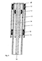
- Figs. 7 , 8 depict sectional views of such a lift-rotary unit.
- This lift-rotary unit comprises e.g. an outer tube 11 fixed standing on the active component 3 ( Fig. 3 ) with four magnetic bearings 12 at the inner circumferential surface within one ore more levels disposed with an angular offset of each 90° between them to bear an inner tube 13 without contact in vertical direction and which is movable supported between two end positions.
- a central lift motor 14 within of it with a fixed standing coil arrangement 15 and also a magnetisable bar 16 vertical disposable within the tube 13.
- the upper free end 18 of the inner tube 13 is used to hold further components like a handler 19 to hold and transport of wafers.
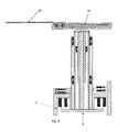
- Fig. 9 shows a combination of a linear and rotary bearing according Fig. 7 with a attached handler 19 which is provided with an electromagnetic disposable fork 20 for carrying a silicon wafer 21 ( Fig. 14 ).
- Fig. 9 is the handler 19 shown with driven out fork 20 in a lower end position and in Fig. 10 in an upper end position with retracted fork 20.
- the handler 19 is also equipped with a contact free bearing and drive.
- Fig. 11 shows the handler 19 according Fig. 10 with a magnetic bearing 22 and an electromagnetic drive 23 with retracted fork 20 ( Fig. 11 ) and with pulled out fork 20 ( Fig. 12 ).
- Fig. 13 depicts a sectional view of the handler in a view A according Fig. 12 with a magnetic bearing 22 and the electromagnetic drive 23.
- Fig. 14 depicts a view B of the handler according Fig. 12 with retracted fork 20 as well as the rotary drive according Fig. 7 .
Landscapes
- Engineering & Computer Science (AREA)
- General Engineering & Computer Science (AREA)
- Mechanical Engineering (AREA)
- Robotics (AREA)
- Container, Conveyance, Adherence, Positioning, Of Wafer (AREA)
- Non-Mechanical Conveyors (AREA)
- Manipulator (AREA)
Claims (10)
- Vorrichtung zur partikelfreien Handhabung von Substraten der Mikrotechnologie in Miniumgebungen unter Reinraumbedingungen, wobei die Vorrichtung eingerichtet ist, ein Substrat längs mehrerer Achsen mit einem Handhaber zu transportieren, der mit einer elektromagnetischen beweglichen Gabel an seinem freien Ende versehen ist, wobei der Handhaber an einer vertikalen Hebedreheinheit gehalten wird, dadurch gekennzeichnet, dass ein elektromagnetisches Linearlager, das mit einer aktiven Komponente (3) versehen ist, in einer passiven Komponente (2) durch lateral befestigte Magnetlager (4, 5) gehalten wird, die die aktive bewegliche Komponente (3) an der passiven Komponente (2) im Gleichgewicht und in der Schwebe halten, wobei die aktive Komponente (3) mit der Hebedreheinheit (10) versehen ist, die mit einem Außenrohr (11) versehen ist, das stehend an der aktiven Komponente (3) befestigt ist, wobei im Außenrohr (11) auf einer oder mehreren Ebenen Magnetlager (12) angeordnet sind, die regelmäßig an der Innenumfangsfläche des Außenrohrs (11) angeordnet sind, um ein Innenrohr (13) berührungslos und in vertikaler Richtung zwischen zwei Endpositionen zu führen.
- Vorrichtung nach Anspruch 1, dadurch gekennzeichnet, dass die bewegliche aktive Einheit (3) über einem Magnetlager (4, 5) hängend an der festen stehenden passiven Komponente (2) geführt wird, wodurch ein an der aktiven Komponente (3) angeordneter Antriebsmotor (7) über eine Kopplungseinheit (6) mit einer Energieversorgung verbunden ist und wodurch an der aktiven Komponente eine Hebedreheinheit (10) mit einem Handhaber (19) angeordnet ist.
- Vorrichtung nach Anspruch 1 und 2, dadurch gekennzeichnet, dass die aktive Komponente (3) mit einem an ihr angeordneten Antriebsmotor (7) versehen ist, der als ein Linearmotor gestaltet ist.
- Vorrichtung nach Anspruch 1 bis 3, dadurch gekennzeichnet, dass an der aktiven Komponente (3) eine elektromagnetische Kopplungsvorrichtung (6) gegenüber festen Spulen (9) an der passiven Komponente (2) angeordnet ist, die als Sendeantenne verwendet werden, um Energie zur aktiven Komponente (3) zu übertragen.
- Vorrichtung nach einem der Ansprüche 1 bis 4, dadurch gekennzeichnet, dass ein zentraler Hebemotor (14) im Innenrohr (13) mit einer festen stehenden Spulenanordnung (15) und einem magnetisierbaren inneren Stab (16) angeordnet ist, der im Rohr (13) vertikal verschiebbar ist.
- Vorrichtung nach Anspruch 5, dadurch gekennzeichnet, dass ein elektromagnetischer Drehantrieb (17) im Innenrohr (13) angeordnet ist, um eine kontrollierbare Rotation des Innenrohrs (13) gegenüber dem Stab (16) zu bewirken.
- Vorrichtung nach einem der Ansprüche 1 bis 6, dadurch gekennzeichnet, dass die Hebedreheinheit (10) vier Magnetlager (12) an der Innenumfangsfläche des Außenrohrs (11) aufweist, die auf einer oder mehreren Ebenen angeordnet sind und mit einem Winkelversatz von jeweils 90° zwischen ihnen angeordnet sind, um das Innenrohr (13) berührungslos in vertikale Richtung zu lagern, das zwischen den beiden Endpositionen beweglich gehalten wird.
- Vorrichtung nach einem der Ansprüche 1 bis 7, dadurch gekennzeichnet, dass das obere freie Ende (18) des Innenrohrs (13) verwendet wird, um weitere Komponenten wie den Handhaber (19) zu halten, um Wafer (21) zu halten und zu transportieren.
- Vorrichtung nach einem der Ansprüche 1 bis 8, dadurch gekennzeichnet, dass eine elektromagnetische bewegliche Gabel (20) am Handhaber (19) angeordnet ist, um einen Siliziumwafer (20) zu halten.
- Vorrichtung nach Anspruch 9, dadurch gekennzeichnet, dass der Handhaber (19) mit einem Magnetlager (22) und einem elektromagnetischen Antrieb (23) versehen ist, um die Gabel (20) einzuziehen oder auszufahren.
Applications Claiming Priority (3)
| Application Number | Priority Date | Filing Date | Title |
|---|---|---|---|
| DE102009022987 | 2009-05-28 | ||
| DE102009038756A DE102009038756A1 (de) | 2009-05-28 | 2009-08-27 | Vorrichtung zur partikelfreien Handhabung von Substraten |
| PCT/EP2010/057236 WO2010136488A1 (en) | 2009-05-28 | 2010-05-26 | Device for particle free handling of substrates |
Publications (2)
| Publication Number | Publication Date |
|---|---|
| EP2436030A1 EP2436030A1 (de) | 2012-04-04 |
| EP2436030B1 true EP2436030B1 (de) | 2013-03-27 |
Family
ID=43049402
Family Applications (1)
| Application Number | Title | Priority Date | Filing Date |
|---|---|---|---|
| EP10726021A Not-in-force EP2436030B1 (de) | 2009-05-28 | 2010-05-26 | Vorrichtung zur partikelfreien handhabung von substraten |
Country Status (11)
| Country | Link |
|---|---|
| US (1) | US20120121371A1 (de) |
| EP (1) | EP2436030B1 (de) |
| JP (1) | JP5773536B2 (de) |
| KR (1) | KR101401007B1 (de) |
| CN (1) | CN102449753A (de) |
| DE (1) | DE102009038756A1 (de) |
| IL (1) | IL216150A0 (de) |
| RU (1) | RU2510546C2 (de) |
| SG (1) | SG176030A1 (de) |
| TW (1) | TWI453854B (de) |
| WO (1) | WO2010136488A1 (de) |
Families Citing this family (10)
| Publication number | Priority date | Publication date | Assignee | Title |
|---|---|---|---|---|
| DE102012200220A1 (de) * | 2011-06-20 | 2012-12-20 | Semilev Gmbh | Verfahren zum Kalibrieren eines aktiv magnetgelagerten Roboters |
| CN105339707A (zh) * | 2013-05-13 | 2016-02-17 | 詹姆斯·约瑟夫·加德纳 | 磁驱动系统和方法 |
| DE102014003882B4 (de) * | 2014-03-19 | 2017-07-13 | Applied Materials, Inc. (N.D.Ges.D. Staates Delaware) | Transportvorrichtung zum Bewegen und/oder Positionieren von Objekten |
| DE102014005547B4 (de) * | 2014-04-16 | 2016-09-15 | Mecatronix Ag | Vorrichtung und Verfahren zum Halten, Positionieren und/oder Bewegen eines Objekts |
| DE102014005897B3 (de) * | 2014-04-25 | 2015-09-17 | Mecatronix Ag | Vorrichtung zum Halten, Positionieren und/oder Bewegen eines Objekts |
| DE102015004582B4 (de) * | 2015-04-09 | 2017-02-09 | Mecatronix Ag | Vorrichtung zum Halten, Positionieren und Bewegen eines Objekts |
| US12321098B2 (en) * | 2017-12-21 | 2025-06-03 | Tokyo Electron Limited | Substrate support member, substrate treatment apparatus, and substrate transfer apparatus |
| DE102022123236A1 (de) * | 2022-09-12 | 2024-03-14 | Mafu Robotics GmbH | Behandlung von Werkstücken insbesondere von Wafern |
| CN119054063A (zh) * | 2022-10-12 | 2024-11-29 | 威克姆真空部件和技术有限公司 | 用于在真空中保持、定位和/或移动物体的设备 |
| WO2024118786A1 (en) * | 2022-11-29 | 2024-06-06 | Onto Innovation Inc. | Two-axis-motion from a linear actuator |
Family Cites Families (25)
| Publication number | Priority date | Publication date | Assignee | Title |
|---|---|---|---|---|
| SU966794A1 (ru) * | 1980-09-18 | 1982-10-15 | Предприятие П/Я Р-6707 | Устройство дл транспортировани деталей |
| JPS6149673A (ja) * | 1984-08-15 | 1986-03-11 | Nippon Telegr & Teleph Corp <Ntt> | 磁気浮上案内装置 |
| JP2732562B2 (ja) | 1986-05-14 | 1998-03-30 | 株式会社東芝 | 浮上式搬送装置 |
| JPH0648845Y2 (ja) * | 1988-04-04 | 1994-12-12 | 日新電機株式会社 | ウエハ搬送装置 |
| JPH024024U (de) * | 1988-06-20 | 1990-01-11 | ||
| US5379212A (en) * | 1990-01-29 | 1995-01-03 | United States Voting Machines, Inc. | Locking memory device |
| US5081439A (en) | 1990-11-16 | 1992-01-14 | International Business Machines Corporation | Thin film resistor and method for producing same |
| JPH0828416B2 (ja) | 1991-02-20 | 1996-03-21 | 株式会社荏原製作所 | ウエハ移送ロボット |
| JPH07114231B2 (ja) * | 1991-02-22 | 1995-12-06 | 株式会社荏原製作所 | ウエハ移送ロボット |
| JPH0596478A (ja) | 1991-10-03 | 1993-04-20 | Seiko Seiki Co Ltd | 磁気浮上型搬送装置 |
| JP3306890B2 (ja) * | 1992-01-24 | 2002-07-24 | 株式会社ダイフク | 移動体の無接触給電設備およびそのピックアップユニット |
| JPH0623687A (ja) * | 1992-02-21 | 1994-02-01 | Ebara Corp | ロボット |
| JPH05228881A (ja) * | 1992-02-21 | 1993-09-07 | Ebara Corp | ロボット |
| US5397212A (en) * | 1992-02-21 | 1995-03-14 | Ebara Corporation | Robot with dust-free and maintenance-free actuators |
| JPH05277970A (ja) * | 1992-03-30 | 1993-10-26 | Ebara Corp | 搬送装置 |
| JP3239320B2 (ja) | 1992-12-14 | 2001-12-17 | 株式会社荏原製作所 | 基板搬送システム |
| JP3350310B2 (ja) * | 1995-08-22 | 2002-11-25 | 株式会社荏原製作所 | ロボットアームのリニアアクチュエータ |
| JPH1159901A (ja) | 1997-08-11 | 1999-03-02 | Murata Mach Ltd | キャリヤー移動装置 |
| JPH11121585A (ja) * | 1997-10-17 | 1999-04-30 | Olympus Optical Co Ltd | ウェハ搬送装置 |
| JP3519595B2 (ja) * | 1998-03-31 | 2004-04-19 | 松下電器産業株式会社 | ウエハ搬送装置 |
| JP2000286318A (ja) * | 1999-01-27 | 2000-10-13 | Shinko Electric Co Ltd | 搬送システム |
| TW579564B (en) * | 2001-08-31 | 2004-03-11 | Asyst Technologies | Unified frame, system for transferring semiconductor wafers and related substrate objects, and system for transporting wafers |
| CN1996553A (zh) * | 2001-08-31 | 2007-07-11 | 阿赛斯特技术公司 | 用于半导体材料处理系统的一体化机架 |
| US20080181758A1 (en) * | 2007-01-29 | 2008-07-31 | Woodruff Daniel J | Microfeature workpiece transfer devices with rotational orientation sensors, and associated systems and methods |
| TWI492826B (zh) * | 2007-06-27 | 2015-07-21 | Brooks Automation Inc | 具有磁浮主軸軸承的自動機械驅動器 |
-
2009
- 2009-08-27 DE DE102009038756A patent/DE102009038756A1/de not_active Withdrawn
-
2010
- 2010-05-26 SG SG2011083318A patent/SG176030A1/en unknown
- 2010-05-26 CN CN2010800233321A patent/CN102449753A/zh active Pending
- 2010-05-26 RU RU2011153241/28A patent/RU2510546C2/ru not_active IP Right Cessation
- 2010-05-26 JP JP2012512357A patent/JP5773536B2/ja not_active Expired - Fee Related
- 2010-05-26 EP EP10726021A patent/EP2436030B1/de not_active Not-in-force
- 2010-05-26 WO PCT/EP2010/057236 patent/WO2010136488A1/en not_active Ceased
- 2010-05-26 KR KR1020117031328A patent/KR101401007B1/ko not_active Expired - Fee Related
- 2010-05-26 US US13/266,648 patent/US20120121371A1/en not_active Abandoned
- 2010-05-27 TW TW099116948A patent/TWI453854B/zh not_active IP Right Cessation
-
2011
- 2011-11-03 IL IL216150A patent/IL216150A0/en unknown
Also Published As
| Publication number | Publication date |
|---|---|
| SG176030A1 (en) | 2011-12-29 |
| KR20120031183A (ko) | 2012-03-30 |
| KR101401007B1 (ko) | 2014-05-29 |
| RU2011153241A (ru) | 2013-07-27 |
| TW201101410A (en) | 2011-01-01 |
| WO2010136488A1 (en) | 2010-12-02 |
| DE102009038756A1 (de) | 2010-12-09 |
| EP2436030A1 (de) | 2012-04-04 |
| JP5773536B2 (ja) | 2015-09-02 |
| RU2510546C2 (ru) | 2014-03-27 |
| TWI453854B (zh) | 2014-09-21 |
| CN102449753A (zh) | 2012-05-09 |
| IL216150A0 (en) | 2012-01-31 |
| US20120121371A1 (en) | 2012-05-17 |
| JP2012528478A (ja) | 2012-11-12 |
Similar Documents
| Publication | Publication Date | Title |
|---|---|---|
| US20120121371A1 (en) | Device for particle free handling of substrates | |
| CN102458778B (zh) | 用于机器人的磁性旋转硬停止件 | |
| CN104428884B (zh) | 吊杆驱动装置、多臂机械手装置、电子器件处理系统及用于在电子器件制造系统中传送基板的方法 | |
| US20130149076A1 (en) | Fully-independent robot systems, apparatus, and methods adapted to transport multiple substrates in electronic device manufacturing | |
| TWI603905B (zh) | 在電子裝置製造中經調適以傳送雙基材的機器人系統、設備和方法 | |
| KR102199674B1 (ko) | 이격된 상부 암들 및 인터리빙된 리스트들을 포함하는 듀얼 로봇, 및 이를 포함하는 시스템들 및 방법들 | |
| US8777547B2 (en) | Systems, apparatus and methods for transporting substrates | |
| JP2023033330A (ja) | 基板処理装置及び基板搬送装置 | |
| JP7686121B2 (ja) | 基板搬送装置、基板搬送方法、および基板処理システム | |
| JP7738090B2 (ja) | 基板移送システムおよびその使用方法 | |
| TW201314828A (zh) | 經調適於電子裝置製造中運輸基板的機器人系統、設備與方法 | |
| JPH0419081A (ja) | 真空内搬送ロボット | |
| JP5627599B2 (ja) | 搬送アーム、及びこれを備える搬送ロボット | |
| WO2013120054A1 (en) | Substrate processing apparatus | |
| US20050286993A1 (en) | Transport apparatus, control method for the same, and vacuum processing system | |
| KR102643087B1 (ko) | 독립적인 액세서리 피드쓰루를 가진 기판 이송 장치 | |
| KR20210128306A (ko) | 기판 이송 장치 | |
| JPH0465853A (ja) | 真空内搬送ロボット | |
| WO2025213266A1 (en) | Displacement system and mover and stator device therefor | |
| JPH04264749A (ja) | ウエハ移送ロボット | |
| JPH0297268A (ja) | 磁気浮上式搬送アーム |
Legal Events
| Date | Code | Title | Description |
|---|---|---|---|
| PUAI | Public reference made under article 153(3) epc to a published international application that has entered the european phase |
Free format text: ORIGINAL CODE: 0009012 |
|
| 17P | Request for examination filed |
Effective date: 20111129 |
|
| AK | Designated contracting states |
Kind code of ref document: A1 Designated state(s): AL AT BE BG CH CY CZ DE DK EE ES FI FR GB GR HR HU IE IS IT LI LT LU LV MC MK MT NL NO PL PT RO SE SI SK SM TR |
|
| DAX | Request for extension of the european patent (deleted) | ||
| 17Q | First examination report despatched |
Effective date: 20121004 |
|
| GRAP | Despatch of communication of intention to grant a patent |
Free format text: ORIGINAL CODE: EPIDOSNIGR1 |
|
| GRAS | Grant fee paid |
Free format text: ORIGINAL CODE: EPIDOSNIGR3 |
|
| GRAA | (expected) grant |
Free format text: ORIGINAL CODE: 0009210 |
|
| AK | Designated contracting states |
Kind code of ref document: B1 Designated state(s): AL AT BE BG CH CY CZ DE DK EE ES FI FR GB GR HR HU IE IS IT LI LT LU LV MC MK MT NL NO PL PT RO SE SI SK SM TR |
|
| REG | Reference to a national code |
Ref country code: GB Ref legal event code: FG4D |
|
| REG | Reference to a national code |
Ref country code: CH Ref legal event code: EP |
|
| REG | Reference to a national code |
Ref country code: AT Ref legal event code: REF Ref document number: 603897 Country of ref document: AT Kind code of ref document: T Effective date: 20130415 |
|
| REG | Reference to a national code |
Ref country code: IE Ref legal event code: FG4D |
|
| REG | Reference to a national code |
Ref country code: CH Ref legal event code: NV Representative=s name: BOVARD AG, CH |
|
| REG | Reference to a national code |
Ref country code: DE Ref legal event code: R096 Ref document number: 602010005826 Country of ref document: DE Effective date: 20130523 |
|
| PG25 | Lapsed in a contracting state [announced via postgrant information from national office to epo] |
Ref country code: BG Free format text: LAPSE BECAUSE OF FAILURE TO SUBMIT A TRANSLATION OF THE DESCRIPTION OR TO PAY THE FEE WITHIN THE PRESCRIBED TIME-LIMIT Effective date: 20130627 Ref country code: SE Free format text: LAPSE BECAUSE OF FAILURE TO SUBMIT A TRANSLATION OF THE DESCRIPTION OR TO PAY THE FEE WITHIN THE PRESCRIBED TIME-LIMIT Effective date: 20130327 Ref country code: NO Free format text: LAPSE BECAUSE OF FAILURE TO SUBMIT A TRANSLATION OF THE DESCRIPTION OR TO PAY THE FEE WITHIN THE PRESCRIBED TIME-LIMIT Effective date: 20130627 Ref country code: LT Free format text: LAPSE BECAUSE OF FAILURE TO SUBMIT A TRANSLATION OF THE DESCRIPTION OR TO PAY THE FEE WITHIN THE PRESCRIBED TIME-LIMIT Effective date: 20130327 |
|
| REG | Reference to a national code |
Ref country code: NL Ref legal event code: T3 |
|
| REG | Reference to a national code |
Ref country code: LT Ref legal event code: MG4D |
|
| PG25 | Lapsed in a contracting state [announced via postgrant information from national office to epo] |
Ref country code: LV Free format text: LAPSE BECAUSE OF FAILURE TO SUBMIT A TRANSLATION OF THE DESCRIPTION OR TO PAY THE FEE WITHIN THE PRESCRIBED TIME-LIMIT Effective date: 20130327 Ref country code: FI Free format text: LAPSE BECAUSE OF FAILURE TO SUBMIT A TRANSLATION OF THE DESCRIPTION OR TO PAY THE FEE WITHIN THE PRESCRIBED TIME-LIMIT Effective date: 20130327 Ref country code: GR Free format text: LAPSE BECAUSE OF FAILURE TO SUBMIT A TRANSLATION OF THE DESCRIPTION OR TO PAY THE FEE WITHIN THE PRESCRIBED TIME-LIMIT Effective date: 20130628 Ref country code: SI Free format text: LAPSE BECAUSE OF FAILURE TO SUBMIT A TRANSLATION OF THE DESCRIPTION OR TO PAY THE FEE WITHIN THE PRESCRIBED TIME-LIMIT Effective date: 20130327 |
|
| PG25 | Lapsed in a contracting state [announced via postgrant information from national office to epo] |
Ref country code: HR Free format text: LAPSE BECAUSE OF FAILURE TO SUBMIT A TRANSLATION OF THE DESCRIPTION OR TO PAY THE FEE WITHIN THE PRESCRIBED TIME-LIMIT Effective date: 20130327 |
|
| PG25 | Lapsed in a contracting state [announced via postgrant information from national office to epo] |
Ref country code: RO Free format text: LAPSE BECAUSE OF FAILURE TO SUBMIT A TRANSLATION OF THE DESCRIPTION OR TO PAY THE FEE WITHIN THE PRESCRIBED TIME-LIMIT Effective date: 20130327 Ref country code: IS Free format text: LAPSE BECAUSE OF FAILURE TO SUBMIT A TRANSLATION OF THE DESCRIPTION OR TO PAY THE FEE WITHIN THE PRESCRIBED TIME-LIMIT Effective date: 20130727 Ref country code: PT Free format text: LAPSE BECAUSE OF FAILURE TO SUBMIT A TRANSLATION OF THE DESCRIPTION OR TO PAY THE FEE WITHIN THE PRESCRIBED TIME-LIMIT Effective date: 20130729 Ref country code: CZ Free format text: LAPSE BECAUSE OF FAILURE TO SUBMIT A TRANSLATION OF THE DESCRIPTION OR TO PAY THE FEE WITHIN THE PRESCRIBED TIME-LIMIT Effective date: 20130327 Ref country code: EE Free format text: LAPSE BECAUSE OF FAILURE TO SUBMIT A TRANSLATION OF THE DESCRIPTION OR TO PAY THE FEE WITHIN THE PRESCRIBED TIME-LIMIT Effective date: 20130327 Ref country code: SK Free format text: LAPSE BECAUSE OF FAILURE TO SUBMIT A TRANSLATION OF THE DESCRIPTION OR TO PAY THE FEE WITHIN THE PRESCRIBED TIME-LIMIT Effective date: 20130327 Ref country code: ES Free format text: LAPSE BECAUSE OF FAILURE TO SUBMIT A TRANSLATION OF THE DESCRIPTION OR TO PAY THE FEE WITHIN THE PRESCRIBED TIME-LIMIT Effective date: 20130708 |
|
| PG25 | Lapsed in a contracting state [announced via postgrant information from national office to epo] |
Ref country code: CY Free format text: LAPSE BECAUSE OF FAILURE TO SUBMIT A TRANSLATION OF THE DESCRIPTION OR TO PAY THE FEE WITHIN THE PRESCRIBED TIME-LIMIT Effective date: 20130327 Ref country code: PL Free format text: LAPSE BECAUSE OF FAILURE TO SUBMIT A TRANSLATION OF THE DESCRIPTION OR TO PAY THE FEE WITHIN THE PRESCRIBED TIME-LIMIT Effective date: 20130327 |
|
| PG25 | Lapsed in a contracting state [announced via postgrant information from national office to epo] |
Ref country code: MC Free format text: LAPSE BECAUSE OF FAILURE TO SUBMIT A TRANSLATION OF THE DESCRIPTION OR TO PAY THE FEE WITHIN THE PRESCRIBED TIME-LIMIT Effective date: 20130327 |
|
| PG25 | Lapsed in a contracting state [announced via postgrant information from national office to epo] |
Ref country code: DK Free format text: LAPSE BECAUSE OF FAILURE TO SUBMIT A TRANSLATION OF THE DESCRIPTION OR TO PAY THE FEE WITHIN THE PRESCRIBED TIME-LIMIT Effective date: 20130327 |
|
| PLBE | No opposition filed within time limit |
Free format text: ORIGINAL CODE: 0009261 |
|
| STAA | Information on the status of an ep patent application or granted ep patent |
Free format text: STATUS: NO OPPOSITION FILED WITHIN TIME LIMIT |
|
| 26N | No opposition filed |
Effective date: 20140103 |
|
| REG | Reference to a national code |
Ref country code: DE Ref legal event code: R097 Ref document number: 602010005826 Country of ref document: DE Effective date: 20140103 |
|
| PGFP | Annual fee paid to national office [announced via postgrant information from national office to epo] |
Ref country code: GB Payment date: 20140528 Year of fee payment: 5 Ref country code: IE Payment date: 20140529 Year of fee payment: 5 |
|
| PGFP | Annual fee paid to national office [announced via postgrant information from national office to epo] |
Ref country code: CH Payment date: 20140528 Year of fee payment: 5 Ref country code: NL Payment date: 20140528 Year of fee payment: 5 Ref country code: DE Payment date: 20140528 Year of fee payment: 5 Ref country code: IT Payment date: 20140528 Year of fee payment: 5 |
|
| PGFP | Annual fee paid to national office [announced via postgrant information from national office to epo] |
Ref country code: BE Payment date: 20140528 Year of fee payment: 5 |
|
| PGFP | Annual fee paid to national office [announced via postgrant information from national office to epo] |
Ref country code: FR Payment date: 20140528 Year of fee payment: 5 |
|
| PG25 | Lapsed in a contracting state [announced via postgrant information from national office to epo] |
Ref country code: MT Free format text: LAPSE BECAUSE OF FAILURE TO SUBMIT A TRANSLATION OF THE DESCRIPTION OR TO PAY THE FEE WITHIN THE PRESCRIBED TIME-LIMIT Effective date: 20130327 |
|
| PG25 | Lapsed in a contracting state [announced via postgrant information from national office to epo] |
Ref country code: SM Free format text: LAPSE BECAUSE OF FAILURE TO SUBMIT A TRANSLATION OF THE DESCRIPTION OR TO PAY THE FEE WITHIN THE PRESCRIBED TIME-LIMIT Effective date: 20130327 |
|
| PG25 | Lapsed in a contracting state [announced via postgrant information from national office to epo] |
Ref country code: TR Free format text: LAPSE BECAUSE OF FAILURE TO SUBMIT A TRANSLATION OF THE DESCRIPTION OR TO PAY THE FEE WITHIN THE PRESCRIBED TIME-LIMIT Effective date: 20130327 |
|
| PG25 | Lapsed in a contracting state [announced via postgrant information from national office to epo] |
Ref country code: LU Free format text: LAPSE BECAUSE OF NON-PAYMENT OF DUE FEES Effective date: 20130526 Ref country code: MK Free format text: LAPSE BECAUSE OF FAILURE TO SUBMIT A TRANSLATION OF THE DESCRIPTION OR TO PAY THE FEE WITHIN THE PRESCRIBED TIME-LIMIT Effective date: 20130327 Ref country code: HU Free format text: LAPSE BECAUSE OF FAILURE TO SUBMIT A TRANSLATION OF THE DESCRIPTION OR TO PAY THE FEE WITHIN THE PRESCRIBED TIME-LIMIT; INVALID AB INITIO Effective date: 20100526 |
|
| REG | Reference to a national code |
Ref country code: DE Ref legal event code: R119 Ref document number: 602010005826 Country of ref document: DE |
|
| REG | Reference to a national code |
Ref country code: CH Ref legal event code: PL |
|
| GBPC | Gb: european patent ceased through non-payment of renewal fee |
Effective date: 20150526 |
|
| PG25 | Lapsed in a contracting state [announced via postgrant information from national office to epo] |
Ref country code: IT Free format text: LAPSE BECAUSE OF NON-PAYMENT OF DUE FEES Effective date: 20150526 Ref country code: LI Free format text: LAPSE BECAUSE OF NON-PAYMENT OF DUE FEES Effective date: 20150531 Ref country code: CH Free format text: LAPSE BECAUSE OF NON-PAYMENT OF DUE FEES Effective date: 20150531 |
|
| REG | Reference to a national code |
Ref country code: NL Ref legal event code: MM Effective date: 20150601 |
|
| REG | Reference to a national code |
Ref country code: IE Ref legal event code: MM4A |
|
| REG | Reference to a national code |
Ref country code: FR Ref legal event code: ST Effective date: 20160129 |
|
| PG25 | Lapsed in a contracting state [announced via postgrant information from national office to epo] |
Ref country code: IE Free format text: LAPSE BECAUSE OF NON-PAYMENT OF DUE FEES Effective date: 20150526 Ref country code: GB Free format text: LAPSE BECAUSE OF NON-PAYMENT OF DUE FEES Effective date: 20150526 Ref country code: NL Free format text: LAPSE BECAUSE OF NON-PAYMENT OF DUE FEES Effective date: 20150601 Ref country code: DE Free format text: LAPSE BECAUSE OF NON-PAYMENT OF DUE FEES Effective date: 20151201 |
|
| PG25 | Lapsed in a contracting state [announced via postgrant information from national office to epo] |
Ref country code: FR Free format text: LAPSE BECAUSE OF NON-PAYMENT OF DUE FEES Effective date: 20150601 |
|
| REG | Reference to a national code |
Ref country code: AT Ref legal event code: MM01 Ref document number: 603897 Country of ref document: AT Kind code of ref document: T Effective date: 20150526 |
|
| PG25 | Lapsed in a contracting state [announced via postgrant information from national office to epo] |
Ref country code: AT Free format text: LAPSE BECAUSE OF NON-PAYMENT OF DUE FEES Effective date: 20150526 |
|
| PG25 | Lapsed in a contracting state [announced via postgrant information from national office to epo] |
Ref country code: BE Free format text: LAPSE BECAUSE OF NON-PAYMENT OF DUE FEES Effective date: 20150531 |
|
| PG25 | Lapsed in a contracting state [announced via postgrant information from national office to epo] |
Ref country code: AL Free format text: LAPSE BECAUSE OF FAILURE TO SUBMIT A TRANSLATION OF THE DESCRIPTION OR TO PAY THE FEE WITHIN THE PRESCRIBED TIME-LIMIT Effective date: 20130327 |