EP2433601B2 - Procédé de fabrication d'un article vestimentaire jetable - Google Patents
Procédé de fabrication d'un article vestimentaire jetable Download PDFInfo
- Publication number
- EP2433601B2 EP2433601B2 EP11195535.7A EP11195535A EP2433601B2 EP 2433601 B2 EP2433601 B2 EP 2433601B2 EP 11195535 A EP11195535 A EP 11195535A EP 2433601 B2 EP2433601 B2 EP 2433601B2
- Authority
- EP
- European Patent Office
- Prior art keywords
- laminated body
- surface web
- wearing article
- elastic
- disposable wearing
- Prior art date
- Legal status (The legal status is an assumption and is not a legal conclusion. Google has not performed a legal analysis and makes no representation as to the accuracy of the status listed.)
- Not-in-force
Links
- 238000004519 manufacturing process Methods 0.000 title claims description 52
- 238000000034 method Methods 0.000 title claims description 12
- 239000006096 absorbing agent Substances 0.000 claims description 60
- 238000005520 cutting process Methods 0.000 claims description 33
- 230000002093 peripheral effect Effects 0.000 claims description 32
- 238000007789 sealing Methods 0.000 claims description 4
- 238000010030 laminating Methods 0.000 claims description 2
- 230000000052 comparative effect Effects 0.000 description 42
- 230000037303 wrinkles Effects 0.000 description 21
- 239000004745 nonwoven fabric Substances 0.000 description 14
- 238000012986 modification Methods 0.000 description 6
- 230000004048 modification Effects 0.000 description 6
- 230000000630 rising effect Effects 0.000 description 5
- 239000000463 material Substances 0.000 description 4
- 239000004831 Hot glue Substances 0.000 description 3
- 239000004698 Polyethylene Substances 0.000 description 3
- 238000006073 displacement reaction Methods 0.000 description 3
- 229920005989 resin Polymers 0.000 description 3
- 239000011347 resin Substances 0.000 description 3
- 229920000247 superabsorbent polymer Polymers 0.000 description 3
- 210000002700 urine Anatomy 0.000 description 3
- 230000008602 contraction Effects 0.000 description 2
- -1 polyethylene Polymers 0.000 description 2
- 229920000573 polyethylene Polymers 0.000 description 2
- 238000012546 transfer Methods 0.000 description 2
- 230000000007 visual effect Effects 0.000 description 2
- 244000043261 Hevea brasiliensis Species 0.000 description 1
- 230000001419 dependent effect Effects 0.000 description 1
- 238000013461 design Methods 0.000 description 1
- 238000004049 embossing Methods 0.000 description 1
- 230000012447 hatching Effects 0.000 description 1
- 230000002209 hydrophobic effect Effects 0.000 description 1
- 238000007689 inspection Methods 0.000 description 1
- 238000003475 lamination Methods 0.000 description 1
- 229920003052 natural elastomer Polymers 0.000 description 1
- 229920001194 natural rubber Polymers 0.000 description 1
- 238000012856 packing Methods 0.000 description 1
- 229920002635 polyurethane Polymers 0.000 description 1
- 239000004814 polyurethane Substances 0.000 description 1
- 238000010298 pulverizing process Methods 0.000 description 1
- 229920003002 synthetic resin Polymers 0.000 description 1
- 239000000057 synthetic resin Substances 0.000 description 1
Images


Classifications
-
- A—HUMAN NECESSITIES
- A61—MEDICAL OR VETERINARY SCIENCE; HYGIENE
- A61F—FILTERS IMPLANTABLE INTO BLOOD VESSELS; PROSTHESES; DEVICES PROVIDING PATENCY TO, OR PREVENTING COLLAPSING OF, TUBULAR STRUCTURES OF THE BODY, e.g. STENTS; ORTHOPAEDIC, NURSING OR CONTRACEPTIVE DEVICES; FOMENTATION; TREATMENT OR PROTECTION OF EYES OR EARS; BANDAGES, DRESSINGS OR ABSORBENT PADS; FIRST-AID KITS
- A61F13/00—Bandages or dressings; Absorbent pads
- A61F13/15—Absorbent pads, e.g. sanitary towels, swabs or tampons for external or internal application to the body; Supporting or fastening means therefor; Tampon applicators
- A61F13/15577—Apparatus or processes for manufacturing
- A61F13/15585—Apparatus or processes for manufacturing of babies' napkins, e.g. diapers
- A61F13/15593—Apparatus or processes for manufacturing of babies' napkins, e.g. diapers having elastic ribbons fixed thereto; Devices for applying the ribbons
-
- A—HUMAN NECESSITIES
- A61—MEDICAL OR VETERINARY SCIENCE; HYGIENE
- A61F—FILTERS IMPLANTABLE INTO BLOOD VESSELS; PROSTHESES; DEVICES PROVIDING PATENCY TO, OR PREVENTING COLLAPSING OF, TUBULAR STRUCTURES OF THE BODY, e.g. STENTS; ORTHOPAEDIC, NURSING OR CONTRACEPTIVE DEVICES; FOMENTATION; TREATMENT OR PROTECTION OF EYES OR EARS; BANDAGES, DRESSINGS OR ABSORBENT PADS; FIRST-AID KITS
- A61F13/00—Bandages or dressings; Absorbent pads
- A61F13/15—Absorbent pads, e.g. sanitary towels, swabs or tampons for external or internal application to the body; Supporting or fastening means therefor; Tampon applicators
- A61F13/15577—Apparatus or processes for manufacturing
- A61F13/15699—Forming webs by bringing together several webs, e.g. by laminating or folding several webs, with or without additional treatment of the webs
-
- A—HUMAN NECESSITIES
- A61—MEDICAL OR VETERINARY SCIENCE; HYGIENE
- A61F—FILTERS IMPLANTABLE INTO BLOOD VESSELS; PROSTHESES; DEVICES PROVIDING PATENCY TO, OR PREVENTING COLLAPSING OF, TUBULAR STRUCTURES OF THE BODY, e.g. STENTS; ORTHOPAEDIC, NURSING OR CONTRACEPTIVE DEVICES; FOMENTATION; TREATMENT OR PROTECTION OF EYES OR EARS; BANDAGES, DRESSINGS OR ABSORBENT PADS; FIRST-AID KITS
- A61F13/00—Bandages or dressings; Absorbent pads
- A61F13/15—Absorbent pads, e.g. sanitary towels, swabs or tampons for external or internal application to the body; Supporting or fastening means therefor; Tampon applicators
- A61F13/15577—Apparatus or processes for manufacturing
- A61F13/15707—Mechanical treatment, e.g. notching, twisting, compressing, shaping
- A61F13/15723—Partitioning batts; Cutting
-
- A—HUMAN NECESSITIES
- A61—MEDICAL OR VETERINARY SCIENCE; HYGIENE
- A61F—FILTERS IMPLANTABLE INTO BLOOD VESSELS; PROSTHESES; DEVICES PROVIDING PATENCY TO, OR PREVENTING COLLAPSING OF, TUBULAR STRUCTURES OF THE BODY, e.g. STENTS; ORTHOPAEDIC, NURSING OR CONTRACEPTIVE DEVICES; FOMENTATION; TREATMENT OR PROTECTION OF EYES OR EARS; BANDAGES, DRESSINGS OR ABSORBENT PADS; FIRST-AID KITS
- A61F13/00—Bandages or dressings; Absorbent pads
- A61F13/15—Absorbent pads, e.g. sanitary towels, swabs or tampons for external or internal application to the body; Supporting or fastening means therefor; Tampon applicators
- A61F13/15577—Apparatus or processes for manufacturing
- A61F13/15756—Applying tabs, strips, tapes, loops; Knotting the ends of pads
-
- A—HUMAN NECESSITIES
- A61—MEDICAL OR VETERINARY SCIENCE; HYGIENE
- A61F—FILTERS IMPLANTABLE INTO BLOOD VESSELS; PROSTHESES; DEVICES PROVIDING PATENCY TO, OR PREVENTING COLLAPSING OF, TUBULAR STRUCTURES OF THE BODY, e.g. STENTS; ORTHOPAEDIC, NURSING OR CONTRACEPTIVE DEVICES; FOMENTATION; TREATMENT OR PROTECTION OF EYES OR EARS; BANDAGES, DRESSINGS OR ABSORBENT PADS; FIRST-AID KITS
- A61F13/00—Bandages or dressings; Absorbent pads
- A61F13/15—Absorbent pads, e.g. sanitary towels, swabs or tampons for external or internal application to the body; Supporting or fastening means therefor; Tampon applicators
- A61F13/45—Absorbent pads, e.g. sanitary towels, swabs or tampons for external or internal application to the body; Supporting or fastening means therefor; Tampon applicators characterised by the shape
- A61F13/49—Absorbent articles specially adapted to be worn around the waist, e.g. diapers
- A61F13/49007—Form-fitting, self-adjusting disposable diapers
- A61F13/49009—Form-fitting, self-adjusting disposable diapers with elastic means
- A61F13/49011—Form-fitting, self-adjusting disposable diapers with elastic means the elastic means is located at the waist region
-
- A—HUMAN NECESSITIES
- A61—MEDICAL OR VETERINARY SCIENCE; HYGIENE
- A61F—FILTERS IMPLANTABLE INTO BLOOD VESSELS; PROSTHESES; DEVICES PROVIDING PATENCY TO, OR PREVENTING COLLAPSING OF, TUBULAR STRUCTURES OF THE BODY, e.g. STENTS; ORTHOPAEDIC, NURSING OR CONTRACEPTIVE DEVICES; FOMENTATION; TREATMENT OR PROTECTION OF EYES OR EARS; BANDAGES, DRESSINGS OR ABSORBENT PADS; FIRST-AID KITS
- A61F13/00—Bandages or dressings; Absorbent pads
- A61F13/15—Absorbent pads, e.g. sanitary towels, swabs or tampons for external or internal application to the body; Supporting or fastening means therefor; Tampon applicators
- A61F13/45—Absorbent pads, e.g. sanitary towels, swabs or tampons for external or internal application to the body; Supporting or fastening means therefor; Tampon applicators characterised by the shape
- A61F13/49—Absorbent articles specially adapted to be worn around the waist, e.g. diapers
- A61F13/49007—Form-fitting, self-adjusting disposable diapers
- A61F13/49009—Form-fitting, self-adjusting disposable diapers with elastic means
- A61F13/4902—Form-fitting, self-adjusting disposable diapers with elastic means characterised by the elastic material
- A61F2013/49025—Form-fitting, self-adjusting disposable diapers with elastic means characterised by the elastic material having multiple elastic strands
-
- A—HUMAN NECESSITIES
- A61—MEDICAL OR VETERINARY SCIENCE; HYGIENE
- A61F—FILTERS IMPLANTABLE INTO BLOOD VESSELS; PROSTHESES; DEVICES PROVIDING PATENCY TO, OR PREVENTING COLLAPSING OF, TUBULAR STRUCTURES OF THE BODY, e.g. STENTS; ORTHOPAEDIC, NURSING OR CONTRACEPTIVE DEVICES; FOMENTATION; TREATMENT OR PROTECTION OF EYES OR EARS; BANDAGES, DRESSINGS OR ABSORBENT PADS; FIRST-AID KITS
- A61F13/00—Bandages or dressings; Absorbent pads
- A61F13/15—Absorbent pads, e.g. sanitary towels, swabs or tampons for external or internal application to the body; Supporting or fastening means therefor; Tampon applicators
- A61F13/45—Absorbent pads, e.g. sanitary towels, swabs or tampons for external or internal application to the body; Supporting or fastening means therefor; Tampon applicators characterised by the shape
- A61F13/49—Absorbent articles specially adapted to be worn around the waist, e.g. diapers
- A61F13/49058—Absorbent articles specially adapted to be worn around the waist, e.g. diapers characterised by the modular concept of constructing the diaper
- A61F2013/49063—Absorbent articles specially adapted to be worn around the waist, e.g. diapers characterised by the modular concept of constructing the diaper the diaper having decoupled components
-
- Y—GENERAL TAGGING OF NEW TECHNOLOGICAL DEVELOPMENTS; GENERAL TAGGING OF CROSS-SECTIONAL TECHNOLOGIES SPANNING OVER SEVERAL SECTIONS OF THE IPC; TECHNICAL SUBJECTS COVERED BY FORMER USPC CROSS-REFERENCE ART COLLECTIONS [XRACs] AND DIGESTS
- Y10—TECHNICAL SUBJECTS COVERED BY FORMER USPC
- Y10T—TECHNICAL SUBJECTS COVERED BY FORMER US CLASSIFICATION
- Y10T156/00—Adhesive bonding and miscellaneous chemical manufacture
- Y10T156/10—Methods of surface bonding and/or assembly therefor
- Y10T156/1052—Methods of surface bonding and/or assembly therefor with cutting, punching, tearing or severing
- Y10T156/1056—Perforating lamina
- Y10T156/1057—Subsequent to assembly of laminae
-
- Y—GENERAL TAGGING OF NEW TECHNOLOGICAL DEVELOPMENTS; GENERAL TAGGING OF CROSS-SECTIONAL TECHNOLOGIES SPANNING OVER SEVERAL SECTIONS OF THE IPC; TECHNICAL SUBJECTS COVERED BY FORMER USPC CROSS-REFERENCE ART COLLECTIONS [XRACs] AND DIGESTS
- Y10—TECHNICAL SUBJECTS COVERED BY FORMER USPC
- Y10T—TECHNICAL SUBJECTS COVERED BY FORMER US CLASSIFICATION
- Y10T156/00—Adhesive bonding and miscellaneous chemical manufacture
- Y10T156/10—Methods of surface bonding and/or assembly therefor
- Y10T156/1052—Methods of surface bonding and/or assembly therefor with cutting, punching, tearing or severing
- Y10T156/1062—Prior to assembly
- Y10T156/1067—Continuous longitudinal slitting
-
- Y—GENERAL TAGGING OF NEW TECHNOLOGICAL DEVELOPMENTS; GENERAL TAGGING OF CROSS-SECTIONAL TECHNOLOGIES SPANNING OVER SEVERAL SECTIONS OF THE IPC; TECHNICAL SUBJECTS COVERED BY FORMER USPC CROSS-REFERENCE ART COLLECTIONS [XRACs] AND DIGESTS
- Y10—TECHNICAL SUBJECTS COVERED BY FORMER USPC
- Y10T—TECHNICAL SUBJECTS COVERED BY FORMER US CLASSIFICATION
- Y10T156/00—Adhesive bonding and miscellaneous chemical manufacture
- Y10T156/10—Methods of surface bonding and/or assembly therefor
- Y10T156/1052—Methods of surface bonding and/or assembly therefor with cutting, punching, tearing or severing
- Y10T156/1084—Methods of surface bonding and/or assembly therefor with cutting, punching, tearing or severing of continuous or running length bonded web
- Y10T156/1087—Continuous longitudinal slitting
Definitions
- the present invention relates to a method of manufacturing disposable wearing articles, such as disposable diapers.
- the invention was devised to solve the problems discussed above, and therefore has an object to provide a manufacturing method of a disposable wearing article that does not raise a problem attributed to the occurrence of wrinkles when the absorber is attached.
- US2002/0092604 discloses a pants-type diaper which is provided with leg-hole elastics which effectively encircle the leg-holes without traversing the crotch region, and methods for producing such diapers.
- the present invention provides a method for manufacturing a disposable wearing article according to claim 1. Certain more specific aspects of the invention are set out in the dependent claims.
- FIG. 1 through FIG. 14 show a disposable wearing article 1A of a first comparative example and a manufacturing method of the same.
- FIG. 9 shows a state where the disposable wearing article 1A is developed.
- FIG. 9A is a plan view
- FIG. 9B is a schematic sectional side elevation
- FIG. 9C is a schematic sectional bottom view.
- FIG. 12 is a front view of the disposable wearing article 1A in a fabricated state.
- the disposable wearing article 1A includes a cover sheet 2 attached to bridge between a front portion (first elastic laminated body 12A) P and a back portion (second elastic laminated body 12B) Q, and an absorber 3 is attached onto the cover sheet 2.
- the front portion P and the back portion Q are placed one on the other by folding the absorber 3 inward with the cover sheet 2 on the outside, and an article of an underpants type as is shown in FIG. 12 is fabricated by side-sealing the both side portions 1a of the front portion P and the back portion Q.
- the both side portions 1a may not be side-sealed, and instead, the both side portions 1a may be stopped in an attachable/detachable manner using a stopper tape or the like, so that an article of a tape type is obtained.
- a crotch portion R is defined by the absorber 3 and leg opening portions S are formed on the both sides of the absorber 3.
- the elastic laminated body 12 is manufactured by bonding an outer surface web 10 and an inner surface web 11 that are made of non-woven fabric and fed continuously in a length direction A while inserting body-fitting elastic members 4 and leg peripheral elastic members 5A and 5B on the front portion P side and the back portion Q side in an extended state in the length direction A in between (see FIGs. 6A through 6c ).
- a breadth W2 of the inner surface web 11 narrower than a breadth W1 of the outer surface web 10.
- leg peripheral elastic member 5A and the body-fitting elastic member 4 are attached linearly in the length direction A, whereas the leg peripheral elastic member 5B is attached in a curved line to go along the concave portion 12b that will be described below.
- a hot melt adhesive is applied on at least one of the webs 10 and 11, so that these webs 10 and 11 are bonded to each other while the body-fitting elastic member 4 and the leg peripheral elastic members 5A and 5B are inserted in between.
- Polyurethane, natural rubber, heat curable resin, etc. can be used as materials of the body-fitting elastic member 4 and the leg peripheral elastic members 5A and 5B. These members can be of a thread shape or a ribbon shape. Also, the number of each member is not limited to one, and each member may be made of more than one thread or ribbon. In a case where heat curable resin is used as the material, when the heat curable resin itself has a capability of bonding the webs 10 and 11, the hot melt adhesive may be omitted. It should be noted that the same description applies to materials and shapes of elastic members 5C, 6, and 7 described below.
- Step 2 The elastic laminated body 12 is cut into the first elastic laminated body 12A and the second elastic laminated body 12B in the length direction A so that concave portions 12a and convex portions (leg peripheral flap portions) 12b appear alternately in Step 3 described in the following.
- portions 12c where contractive forces are lessened are formed by applying treatment to lessen contractive forces of the body-fitting elastic members 4 and the leg peripheral elastic members 5A and 5B in the concave portions 12a and the convex portions 12b on the second elastic laminated body 12B side.
- a method of fusing the body-fitting elastic member 4 and the leg peripheral elastic members 5A and 5B using an embossed roll (heat embossing) (see JP-A-2002-113042 ), or a method of cutting the body-fitting elastic member 4 and the leg peripheral elastic members 5A and 5B using a gather cutter 14 (see FIG. 1 ) can be adopted. It is preferable to fuse or cut these members while the elastic laminated body 12 placed along the roll is drawn in vacuum.
- the step of lessening contractive forces can be performed at any timing before Step 11 of attaching the absorber 3 described below.
- the first elastic laminated body 12A and the second elastic laminated body 12B are manufactured by cutting the elastic laminated body 12 in the length direction A using an S-cutter 15 (so-called S-cutting, see a cutting line C), so that the concave portions 12a and the convex portions 12b appear alternately in the elastic laminated body 12 (see FIG. 6D ).
- the cutting may be made in the form of a perforated line so that laminated bodies can be separated at the time of spacing described below.
- FIG. 13 when the elastic laminated body 12 is cut into the first elastic laminated body 12A and the second elastic laminated body 12B by the S-cutting (see the cutting line C), circular arc portions indicated by hatching a are left on the both sides of the first elastic laminated body 12A. These circular arc portions may be left intact or may be cut off from the design consideration.
- FIG. 9 through FIG. 12 show the disposable wearing article 1A of an underpants type with these portions being cut off.
- a length W8 of the elastic laminated body 12A in the width direction may be extended.
- the raise length can be extended, which can in turn increase the commercial value.
- Step 4 The liquid-impermeable cover sheet 2 continuously fed in the length direction A is folded in the shape of ⁇ by providing slack comparable to the spacing described below, and then cut in a specific width W3 (see FIG. 2 ) using cut and place rollers 20 (A and B). The cover sheet 2 thus cut is bonded to bridge between the inner surface webs 11 on the concave portion 12a and the convex portion 12b of the first elastic laminated body 12A and the second elastic laminated body 12B, respectively (see FIG. 6E ).
- the cover sheet 2 folded in the shape of ⁇ is cut by the cut roller 20A, then transported on the place roller 20B, and bonded to bridge between the inner surface webs 11 on the concave portion 12a and the convex portion 12b of the first elastic laminated body 12A and the second elastic laminated body 128, respectively, on a back sheet lamination drum 50.
- the cover sheet 2 can be hydrophobic non-woven fabric, such as PP and PE.
- the width W3 is set to be almost equal to that of the absorber 3 and the length is set shorter than that of the absorber 3. By taking into account displacement in width caused when the absorber 3 is attached, it is preferable in practice to set the width W3 of the cover sheet 2 about 6 to 13% wider.
- Step 5 The cut first elastic laminated body 12A and second elastic laminated 12B are spaced by a specific interval W4 in the width direction W (see FIG. 6F ).
- the cover sheet 2 is thus expanded to be flat and bridge between the concave portions 12a and the convex portions 12b of the first elastic laminated body 12A and the second elastic laminated body 12B, respectively.
- a sheet for rising flaps 8 that is made of non-woven fabric and fed continuously in the length direction A is cut in the length direction A by a slitter 16 (see FIG. 7A ).
- the cut rising flaps 8 are spaced by a specific interval W5 in the width direction W (see FIG. 7B ).
- a flap elastic member 7 in an extended state in the length direction A is inserted and bonded to the interior of an incurved portion 8a of each rising flap 8 curled inwardly using a sailor 28 (see FIGs. 7C and 7D ).
- rear anchor portions 8b of the rising flaps 8 are bonded to the both side portions of a top sheet 9A that is made of liquid-permeable non-woven fabric and fed continuously in the length direction A (see FIG. 7E ).
- a core 3a of the absorber 3 is molded in a longitudinal flow state by laminating fibrillated fluff made by pulverizing a roll pulp 17 using a pulverizer 18 on a pattern drum 19.
- the fluff may be mixed with super absorbent polymer.
- Step 8 Leg peripheral elastic members 5C in an extended state in the length direction A are attached along the both side portions of a back sheet 9B that is made of non-woven fabric and fed continuously in the length direction A while a liquid-impermeable synthetic resin film 9b is bonded to the back surface.
- the back sheet 9B may be made of only a liquid-impermeable waterproof film, such as a polyethylene film, in this step.
- the leg peripheral elastic members are also attached along the both side portions in the same manner.
- Step 9 The absorber 3 in a lengthy state in the length direction A is manufactured by placing the core 3a on the back sheet 9B manufactured in Step 8, and bonding the top sheet 9A manufactured in Step 6 to the back sheet 9B with a hot melt adhesive or the like while the core 3a and the leg peripheral elastic members 5C are inserted in between (see FIG. 7F ).
- liquid-impermeable sheet a polyethylene film or a water-shedding or breathable non-woven fabric is preferable.
- liquid-permeable sheet a liquid- permeable non-woven fabric or a mesh sheet is preferable.
- Step 10 The absorber 3 of a rectangular shape is manufactured by cutting the absorber 3 in a lengthy state in the length direction A together with the rising flaps 8 at every specific length using an interior cutter 21.
- a transfer sheet 29 (see FIG. 9 ) may be interposed between the core 3a and the top sheet 9A.
- the transfer sheet 29 diffuses urine or the like quickly and prevents leakage of absorbed urine or the like from the top sheet 9A.
- the core 3a is molded by mixing the super absorbent polymer with the fluff, it is possible to prevent the super absorbent polymer from coming out from the fluff by sandwiching the core 3a between two sheets of tissue paper or wrapping the core 3a in a single sheet of tissue paper.
- Step 11 Referring to FIG. 1 , FIG. 4 , and FIG. 8 , as with the first elastic laminated body 12A and the second elastic laminated body 12B in a transverse flow state manufactured in Step 5, the absorber 3 manufactured in Step 10 is brought into a transverse flow state by being inverted by 90 degrees using an interior turn drum 23 (see the left end of FIG. 3 ), and the absorber 3 is bonded onto the cover sheet 2 bonded to bridge between the first elastic laminated body 12A and the second elastic laminated body 12B, and is also bonded to bridge between the inner surface webs 11 on the concave portion 12a and the convex portion 12b of the first elastic laminated body 12A and the second elastic laminated body 12B, respectively (see FIG. 8A ). In this case, the absorber 3 is bonded across the portion 12c where contractive forces of the concave portion 12a and the convex portion 12b are lessened.
- Waist elastic members 6 in an extended state in the length direction A are placed along the both end portions 12d of the first elastic laminated body 12A and the second elastic laminated body 12B in the width direction (a direction crossing with the length direction A) W on the outer surface web 10 side.
- the both end portions 12d are folded inward, so that the absorber 3 is bonded to the inner side of the both end portions 12d while the waist elastic members 6 are inserted in between (see FIGs. 8B and 8C ).
- leg hole portions S as described below may be formed by cutting out the first elastic laminated body 12A and the second elastic laminated body 12B using a trim cutter (not shown). Further, the both edge portions of the cover sheet may be cut off or the both edge portions of the absorber 3 may be cut off.
- Step 13 The first elastic laminated body 12A and the second elastic laminated body 12B are placed one on the other by folding the absorber 3 inward with the cover sheet 2 on the outside using a doubling device 24 (see FIG. 8D ).
- Step 14 The intermediate position (equivalent to the both side portions 1a of the disposable wearing article 1A) of the absorber 3 adjacent to the first elastic laminated body 12A and the second elastic laminated body 12B placed one on the other is side-sealed by fusing heat seals 25a through 25c in several steps.
- the heat seals 25a through 25c are not necessarily in the several steps. Instead of using the heat seals 25a through 25c, the side-sealing may be performed using sonic.
- the disposable wearing article 1A with the both side portions 1a being side-sealed can be achieved by cutting the intermediate portion in the sidesealed portions of the first elastic laminated body 12A and the second elastic laminated body 12B using a product cutter 26.
- Step 16 The disposable wearing article 1A as the product is inverted by 90 degrees by a product inverting device 27, and transported to a product inspection step and to a packing step.
- the elastic laminated body 12 is manufactured by bonding the two webs 10 and 11 while inserting the elastic members 4, 5A, and 5B in between.
- the elastic laminated body 12 is then cut in the length direction A so that the concave portions 12a and the convex portions 12b appear alternately.
- the cover sheet 2 is bonded to bridge between the concave portion 12a and the convex portion 12b of the cut first elastic laminated body 12A and second elastic laminated body 12B, respectively, the first elastic laminated body 12A and the second elastic laminated body 12B are spaced.
- the absorber 3 is then attached onto the cover sheet 2.
- the cover sheet 2 is therefore bonded to bridge between the first elastic laminated body 12A and the second elastic laminated body 12B not after the spacing when wrinkles are readily produced in the elastic laminated body 12, but before the spacing when wrinkles are hardly produced, more specifically, immediately after the cutting. It is thus possible to avoid a problem attributed to wrinkles and arising when the absorber 3 is attached.
- the method is particularly effective in a case where the wrinkles and/or creases are more readily produced as described above, for example, in a case where the leg peripheral elastic member 5B is inserted in the convex portion 12b.
- the bonding can be readily performed by bonding the cover sheet 2 provided with slack comparable to the spacing to bridge between the first elastic laminated body 12A and the second elastic laminated body 12B.
- a stretchable sheet may be used as the cover sheet 2.
- a stretchable absorber 3 can be used, which can in turn improve the feeling of fitness of the wearer.
- the width W3 of the cover sheet 2 is almost equal to that of the absorber 3 and by setting the length shorter than that of the absorber 3, the material costs can be saved in comparison with a manufacturing method of manufacturing the cover sheet 2 integrally with the absorber 3.
- the cutting in the elastic laminated body 12 in the form of a perforated line so that the laminated bodies can be separated at the time of spacing, it is possible to forestall a problem that wrinkles are readily produced at the same time instant the cutting is performed.
- the waist elastic members 6, the body-fitting elastic member 4, and the leg peripheral elastic member 5A and 5B are attached to the first elastic laminated body 12A and the second elastic laminated body 12B, it is possible to prevent the disposable wearing article 1A put on the wearer from drooping down by the waist elastic member 6, while the disposable wearing article 1A can be fit to the body by the body-fitting elastic members 4 and the adhesion to the leg portions can be enhanced by the leg peripheral elastic members 5A and 5B.
- the cover sheet 2 is bonded to bridge between the first elastic laminated body 12A and the second elastic laminated body 12B obtained by cutting the elastic laminated body 12 manufactured by bonding the two webs 10 and 11 while inserting the elastic members 4, 5A, and 5B in between.
- the cover sheet 2 may be bonded to bridge between a first web and a second web obtained by cutting a single web 11. It should be noted that the waist elastic member 6 that has no influence on the occurrence of wrinkles can be attached.
- the leg peripheral elastic member 5B on the second elastic laminated body 12B (back portion Q) side is attached in a curved line state b in the width direction of the wearing article.
- the leg peripheral elastic member 5B can be attached to include both the curved line state b and a linear state c in the width direction of the wearing article.
- the leg peripheral elastic member 5B can be attached in the linear state c in the width direction of the wearing article.
- the body-fitting elastic member 4 may be attached to the first elastic laminated body 12A (front portion P).
- FIG. 15 through FIG. 17 show a manufacturing method of a disposable wearing article 1B of a second comparative example.
- the disposable wearing article 1B of the second comparative example is different in that the cover sheet 2 is omitted.
- the manufacturing method of the disposable wearing article 1B of the second comparative example will now be described in points different from the manufacturing method of the disposable wearing article 1A of the first comparative example.
- the outer surface web 10 that is made of nonwoven fabric and fed continuously in the length direction A is cut in the length direction A using the slitter 16 (see a cutting line D). Cut first outer surface web 10A and second outer surface web 10B are spaced by a specific interval W6 in the width direction W.
- the inner surface web 11 that is made of non-woven fabric and fed continuously in the length direction A is cut in the length direction A using the S-cutter 15 so that the concave portions 12a and the convex portions 12b appear alternately (so-called S-cutting, see the cutting line C).
- Cut first inner surface web 11A and second inner surface web 11B are spaced by a specific interval W6 in the width direction W, and are shifted in the length direction A by a phase matching device 13 so that the concave portions 12b of the respective webs 11A and 11B oppose each other.
- the phase matching can be performed after the first outer surface web 10A and the first inner surface web 11A are bonded, after the second outer surface web 10B and the second inner surface web 11B are bonded (see Step 1 of FIG. 1 ), or after the portion 12c where contractive forces are lessened is formed (see Step 2 of FIG. 1 ).
- the phase matching can be performed at any timing from the spacing step to the bonding step of the absorber 3.
- both the webs 10A and 11A and the webs 10B and 11B become firm, they can be handled more readily. It should be noted, however, that the phase matching can be omitted as in the first comparative example.
- the first elastic laminated body 12A on the front portion P side and the second elastic laminated body 12B on the back portion Q side are manufactured by bonding the first outer surface web 10A to the first inner surface web 11A and the second outer surface web 10B to the second inner surface web 11B, all of which are cut and spaced, while inserting the bodyfitting elastic members 4 on the front portion P side and the back portion Q side in an extended state in the length direction A in between.
- the second outer surface web 10B and the second inner surface web 11B may be bonded while inserting the leg peripheral elastic member 5B in between.
- the absorber 3 is bonded across the portion 12c where contractive forces at the convex portions 12b of the inner surface webs 11 in the first elastic laminated body 12A and the second elastic laminated body 12B are lessened.
- leg hole portions S are formed by cutting out the outer surface web 10 using a trim cutter 22 provided between Step 12 and Step 13.
- the outer surface web 10 alone is cut out using the trim cutter 22.
- the inner surface web 11 may be cut out as well, or alternatively, the both edge portions of the absorber 3 may be cut off together with the outer surface web 10 and the inner surface web 11.
- the outer surface web 10 is cut in the length direction A, and the cut first outer surface web 10A and second outer surface web 10B are spaced.
- the inner surface web 11 is cut in the length direction A so that the concave portions 12a and the convex portions 12b appear alternately, and the cut first inner surface web 11A and second inner surface web 11B are followed by the phase matching.
- the absorber 3 is bonded to bridge between the convex portions 12b of the first inner surface web 11A and the second inner surface web 11B.
- the outer surface web 10 is therefore in a seamless state in the constant width in the width direction, and transported in open width while tension in the length direction is kept applied.
- the outer surface web 10 therefore has a resistance against contraction of the bodyfitting member 4 inserted between the self and the inner surface web 11.
- the occurrence of wrinkles in the convex portions 12b of the manufactured first elastic laminated body 12A and second elastic laminated body 12B can be suppressed in comparison with a case where both the outer surface web 10 and the inner surface web 11 have the concave portion and the convex portion. It is thus possible to avoid a problem attributed to the occurrence of wrinkles when the absorber 3 is attached to bridge between the convex portions 12b of the first inner surface web 11 and the second inner surface web 11B.
- the method is particularly effective in a case where the wrinkles and/or creases are readily produced as described above, for example, when the leg peripheral elastic member 5B is inserted in the convex portion 12b.
- the cover sheet 2 used in the first comparative example can be omitted, the cost can be saved.
- the wearing article can be approximated to underpants in shape.
- the visual quality can be therefore improved, which can in turn increase the commercial value of the disposable wearing article 1B.
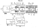
- FIG. 18 and FIG. 19 show a manufacturing method of a disposable wearing article 1C of an embodiment.
- the disposable wearing article 1C of the embodiment is different in that the outer surface web 10 is neither cut nor spaced.
- the manufacturing method of the disposable wearing article 1C of the embodiment will now be described in points different from the manufacturing method of the disposable wearing article 1B of the second embodiment.
- the step of cutting and spacing the outer surface web 10 (see a portion indicated by a capital F) and the step of bonding the film 9b of the back sheet 9B (see a portion indicated by a capital G) can be omitted.
- the inner surface web 11 that is made of non-woven fabric and fed continuously in the length direction A is cut in the length direction A using the S-cutter 15 so that the concave portions 12a and the convex portions 12b appear alternately (so-called S-cutting, see the cutting line C), and the cut first inner surface web 11A and second inner surface web 11B are spaced by a specific interval W6 in the width direction W while being shifted in the length direction A by the phase matching device 13 so that the convex portions 12b of the respective webs 11A and 11B oppose each other.
- the phase matching can be omitted as in the first comparative example.
- the outer surface web 10 that is made of nonwoven fabric set to have a breadth W7 in a spaced state and fed continuously in the length direction A is bonded to the first inner surface web 11A and the second inner surface web 11B while inserting the body-fitting elastic members 4 on the front portion P side and the back portion Q side in an extended state in the length direction A in between.
- the first elastic laminated body 12A on the front portion P side and the second elastic laminated body 12B on the back portion Q side are thus manufactured while being connected via the outer surface web 10.
- the outer surface web 10 may be bonded to the second inner surface web 11B while inserting the leg peripheral elastic member 5B in between.
- the absorber 3 is bonded not only across the portion 12c where contractive forces at the convex portions 12b of the inner surface webs 11 in the first elastic laminated body 12A and the second elastic laminated body 12B are lessened, but also onto the seamless outer surface web 10.
- leg hole portions S are formed by cutting out the outer surface web 10 using the trim cutter 22 provided between Step 12 and Step 13.
- the outer surface web 10 alone is cut out using the trim cutter 22.
- the inner surface web 11 may be cut out as well, or alternatively, the both edge portions of the absorber 3 may be cut off together with the outer surface web 10 and the inner surface web 11.
- the inner surface web 11 is cut in the length direction A so that the concave portions 12a and the convex portions 12b appear alternately, and the cut first inner surface web 11A and second inner surface web 11B are spaced.
- the first elastic laminated body 12A and the second elastic laminated body 12B connected via the outer surface web 10 are manufactured by bonding the outer surface web 10 that is set to have the breadth W7 in a spaced state is bonded to the first inner surface web 11A and to the second inner surface web 11B while inserting the body-fitting elastic members 4 in between, the absorber 3 is bonded to bridge between the convex portions 12b of the first inner surface web 11A and the second inner surface web 11B.
- the outer surface web 10 is therefore neither cut nor spaced, and transported in open width while tension in the length direction is kept applied.
- the outer surface web 10 thus has a resistance against the contraction of the body-fitting elastic members 4 inserted between the self and the inner surface web 11. It is thus possible to avoid a problem attributed to the occurrence of wrinkles and arising when the absorber is attached to bridge between the convex portions 12b of the first inner surface web 11A and the second inner surface web 11B.
- the method of the invention is particularly effective in a case where the wrinkles and/or creases are readily produced as described above, for example, when the leg peripheral elastic member 5B is inserted in the convex portion 12b.
- the cover sheet 2 used in the first comparative example can be omitted, the cost can be saved.
- the intermediate portion of the absorber 3 can be covered with the seamless outer surface web 10, the visual quality is increased.
- FIG. 20 through FIG. 24 show a manufacturing method of a disposable wearing article 1D of a third comparative example.
- the disposable wearing article 1D of the third comparative example is different in that the inner surface web is not S-cut.
- the manufacturing method of the disposable wearing article 1D of the third comparative example will now be described in points different from the manufacturing method of the disposable wearing article 1B of the second comparative example.
- the elastic laminated body 12 is manufactured by bonding the outer surface web 10 and the inner surface web 11 that are fed continuously in the length direction A while inserting the body-fitting elastic members 4 and the leg peripheral elastic members 5A and 5B on the front portion P side and the back portion Q side in an extended state in the length direction A in between.
- the elastic laminated body 12 is cut in the length direction A using the slitter 16 (see the cutting line D), and the cut first elastic laminated body 12A and second elastic laminated body 12B are spaced by a specific interval W6 in the width direction W.
- the absorber 3 is bonded across the portion 12c where contractive forces of the inner surface webs 11 in the first elastic laminated body 12A and the second elastic laminated body 12B are lessened.
- leg hole portions S are formed by cutting out the first elastic laminated body 12A and the second elastic laminated body 12B using the trim cutter 22 provided between Step 12 and Step 13.
- the both edge portions of the absorber 3 may be also cut off.
- the leg hole portions S are cut out after the absorber 3 is bonded to bridge between the spaced first elastic laminated body 12A and second elastic laminated body 12B.
- the absorber 3 can be therefore provided in the absence of a problem attributed to occurrence of wrinkles as described above.
- leg peripheral elastic members 5C that cross with the leg peripheral elastic member 5A on the front portion P side and the leg peripheral elastic member 5B on the back portion Q side may be attached to the absorber 3. Also, as is shown in FIG. 24 , the leg peripheral elastic member 5B on the back portion Q side may be attached in a curved line along the back edge portion of the back portion Q instead of being attached linearly.
- FIG. 25 through FIG. 27 show a manufacturing method of a disposable wearing article 1E of a fourth comparative example.
- the disposable wearing article 1E of the fourth comparative example is different in that the inner surface web is not S-cut.
- the manufacturing method of the disposable wearing article 1E of the fourth comparative example will now be described in points different from the manufacturing method of the disposable wearing article 1B of the embodiment.
- the inner surface web 11 that is made of nonwoven fabric and fed continuously in the length direction A is cut in the length direction A (see the cutting line D) using the slitter 16, and the cut first inner surface web 11A and second inner surface web 11B are spaced by a specific interval W6 in the width direction W.
- the outer surface web 10 that is made of nonwoven fabric set to have a breadth W7 in a spaced state and fed continuously in the length direction A is bonded to the first inner surface web 11A and to the second inner surface web 11B while inserting the body-fitting elastic members 4 and the leg peripheral elastic members 5A and 5B on the front portion P side and the back portion Q side in an extended state in the length direction A in between.
- the first elastic laminated body 12A on the front portion P side and the second elastic laminated body 12B on the back portion Q side are thus manufactured while being connected via the outer surface web 10.
- the absorber 3 is bonded not only across the portion 12c where contractive forces of the inner surface webs 11 in the first elastic laminated body 12A and the second elastic laminated body 12B are lessened, but also onto the seamless outer surface web 10.
- leg hole portions S are formed by cutting out the first elastic laminated body 12A and the second elastic laminated body 12B using the trim cutter 22 provided between Step 12 and Step 13.
- the both edge portions 3b of the absorber 3 are also cut off using the trim cutter 22 in this embodiment.
- the leg hole portions S are cut out after the absorber 3 is bonded to bridge between the first elastic laminated body 12A and second elastic laminated body 12B connected via the outer surface web 10.
- the absorber 3 can be therefore provided in the absence of a problem attributed to the occurrence of wrinkles as described above.
Claims (4)
- Procédé de fabrication d'un article vestimentaire jetable, comprenant:une étape consistant à couper une bande de surface intérieure (11) dans une direction de longueur de celle-ci (A) pour former une première bande de surface intérieure (11A) et une seconde bande de surface intérieure (11B);une étape consistant à écarter la première bande de surface intérieure et la seconde bande de surface intérieure coupées l'une de l'autre dans une direction de largeur (W);une étape consistant à fabriquer un premier corps élastique stratifié (12A) et un second corps élastique stratifié (12B) par stratification d'une bande de surface extérieure sur la première bande de surface intérieure et la seconde bande de surface intérieure tout en insérant un élément élastique (4, 5A, 5B) dans un état étendu dans la direction de longueur entre celles-ci; etune étape consistant à fixer un absorbant (3) pour relier la première bande de surface intérieure et la seconde bande de surface intérieure,caractérisé en ce que la bande de surface intérieure est coupée sur une seule ligne (C) dans la direction de longueur; et en ce que la bande de surface intérieure est coupée dans la direction de longueur de façon à faire apparaître une partie concave et une partie convexe alternées.
- Procédé de fabrication d'un article vestimentaire jetable selon la revendication 1, comprenant en outre une étape consistant à décaler les première et seconde bandes intérieures coupées dans la direction de la longueur de sorte que leurs parties concaves respectives s'opposent.
- Procédé de fabrication d'un article vestimentaire jetable selon la revendication 1 ou la revendication 2, dans lequel:
l'élément élastique comprend un élément élastique ventral (6), un élément élastique ajusté au corps (4) et un élément élastique périphérique de jambe (5), et l'élément élastique périphérique de jambe est dans un état où l'élément élastique périphérique de jambe est prévu dans un état linéaire ou un état de ligne incurvée dans une direction de largeur de l'article vestimentaire ou dans un état présentant les deux états. - Procédé de fabrication d'un article vestimentaire jetable selon l'une quelconque des revendications 1 à 3, comprenant en outre:
une étape consistant à sceller latéralement les deux parties latérales (1A) du premier corps élastique stratifié et du second corps élastique stratifié alors que l'absorbant est dans un état plié.
Applications Claiming Priority (3)
| Application Number | Priority Date | Filing Date | Title |
|---|---|---|---|
| JP2003288204 | 2003-08-06 | ||
| EP04748288A EP1661535B1 (fr) | 2003-08-06 | 2004-08-04 | Article vestimentaire jetable |
| PCT/JP2004/011498 WO2005013871A1 (fr) | 2003-08-06 | 2004-08-04 | Article jetable a porter sur le corps |
Related Parent Applications (2)
| Application Number | Title | Priority Date | Filing Date |
|---|---|---|---|
| EP04748288.0 Division | 2004-08-04 | ||
| EP04748288A Division EP1661535B1 (fr) | 2003-08-06 | 2004-08-04 | Article vestimentaire jetable |
Publications (3)
| Publication Number | Publication Date |
|---|---|
| EP2433601A1 EP2433601A1 (fr) | 2012-03-28 |
| EP2433601B1 EP2433601B1 (fr) | 2016-05-25 |
| EP2433601B2 true EP2433601B2 (fr) | 2019-11-13 |
Family
ID=34131504
Family Applications (2)
| Application Number | Title | Priority Date | Filing Date |
|---|---|---|---|
| EP04748288A Not-in-force EP1661535B1 (fr) | 2003-08-06 | 2004-08-04 | Article vestimentaire jetable |
| EP11195535.7A Not-in-force EP2433601B2 (fr) | 2003-08-06 | 2004-08-04 | Procédé de fabrication d'un article vestimentaire jetable |
Family Applications Before (1)
| Application Number | Title | Priority Date | Filing Date |
|---|---|---|---|
| EP04748288A Not-in-force EP1661535B1 (fr) | 2003-08-06 | 2004-08-04 | Article vestimentaire jetable |
Country Status (5)
| Country | Link |
|---|---|
| US (2) | US7754044B2 (fr) |
| EP (2) | EP1661535B1 (fr) |
| JP (2) | JP4643449B2 (fr) |
| CN (1) | CN1829491B (fr) |
| WO (1) | WO2005013871A1 (fr) |
Families Citing this family (47)
| Publication number | Priority date | Publication date | Assignee | Title |
|---|---|---|---|---|
| DE112006003366B4 (de) | 2005-12-16 | 2017-03-30 | Zuiko Corp. | Verfahren zur Herstellung eines tragbaren Artikels |
| JP4824452B2 (ja) * | 2006-03-30 | 2011-11-30 | 株式会社リブドゥコーポレーション | 使い捨て吸収性物品の製造方法 |
| MX2008014154A (es) * | 2006-05-12 | 2008-11-18 | Sca Hygiene Prod Ab | Articulo absorbente del tipo de calzoncillos y un metodo para producir articulos absorbentes de tipo de calzoncillos. |
| WO2007133128A1 (fr) * | 2006-05-12 | 2007-11-22 | Sca Hygiene Products Ab | Stratifié élastique et son procédé de production |
| US8439888B2 (en) * | 2006-06-01 | 2013-05-14 | Kimberly-Clark Worldwide, Inc. | Three-piece disposable absorbent article having an absorbent with cross-direction flexibility |
| CN101466337B (zh) * | 2006-06-13 | 2012-11-28 | 株式会社瑞光 | 一次性穿戴物品的制造方法 |
| EP2638888B1 (fr) * | 2007-09-05 | 2015-01-28 | Uni-Charm Corporation | Article absorbant |
| JP5270126B2 (ja) * | 2007-09-05 | 2013-08-21 | ユニ・チャーム株式会社 | 使い捨ておむつの製造方法 |
| DE102007063209A1 (de) * | 2007-12-20 | 2009-06-25 | Paul Hartmann Aktiengesellschaft | Verfahren zum Herstellen von Inkontinenzartikeln in Höschenform |
| US20100163161A1 (en) * | 2008-12-30 | 2010-07-01 | Eric-John Raoul Gilgenbach | Process For Making Disposable Absorbent Garments Employing Elastomeric Film Laminates With Deactivated Regions |
| JP5515294B2 (ja) * | 2009-01-16 | 2014-06-11 | 王子ホールディングス株式会社 | ウエストベルトの製造方法及び使い捨ておむつの製造方法 |
| JP5453827B2 (ja) * | 2009-02-09 | 2014-03-26 | 王子ホールディングス株式会社 | ウエストベルトの製造方法及び使い捨ておむつの製造方法 |
| JP5475356B2 (ja) * | 2009-07-31 | 2014-04-16 | ユニ・チャーム株式会社 | 吸収性物品の製造方法及び吸収性物品の製造装置 |
| US8753466B2 (en) * | 2009-10-23 | 2014-06-17 | Kimberly-Clark Worldwide, Inc. | Method of making disposable absorbent garments employing elastomeric film laminate body panels |
| JP5457822B2 (ja) * | 2009-12-22 | 2014-04-02 | ユニ・チャーム株式会社 | 使い捨て着用物品 |
| US8622983B2 (en) * | 2009-12-31 | 2014-01-07 | Kimberly-Clark Worldwide, Inc. | Method of incorporating leg elastics in a pant-like disposable absorbent garment, and garment made thereby |
| JP5595055B2 (ja) * | 2010-01-29 | 2014-09-24 | ユニ・チャーム株式会社 | 吸収性物品の製造方法 |
| JP5534839B2 (ja) * | 2010-01-29 | 2014-07-02 | ユニ・チャーム株式会社 | 吸収性物品 |
| JP5574785B2 (ja) * | 2010-04-01 | 2014-08-20 | ユニ・チャーム株式会社 | おむつ、およびおむつの製造方法 |
| CN103189028B (zh) * | 2010-11-18 | 2015-01-21 | 株式会社瑞光 | 一次性穿戴物品的制造方法 |
| US20120152446A1 (en) * | 2010-12-16 | 2012-06-21 | Rhodes Brian K | Method of incorporating oscillating elastic into disposable garments |
| JP5889153B2 (ja) * | 2011-09-26 | 2016-03-22 | 株式会社瑞光 | 使い捨て着用物品の製造方法 |
| JP6009800B2 (ja) | 2012-04-12 | 2016-10-19 | 株式会社リブドゥコーポレーション | 吸収性物品 |
| CN104284641B (zh) * | 2012-05-15 | 2016-08-24 | 宝洁公司 | 具有有利的拉伸和可制造性特征结构的一次性吸收裤及其制造方法 |
| CN104302260B (zh) * | 2012-05-15 | 2016-08-17 | 宝洁公司 | 带有多个层中的弹性部件的吸收制品 |
| US20130310795A1 (en) * | 2012-05-15 | 2013-11-21 | The Procter & Gamble Company | Absorbent articles with uniform graphics |
| JP6095305B2 (ja) * | 2012-09-13 | 2017-03-15 | 株式会社瑞光 | 複合収縮部材を用いた着用物品及び該着用物品の製造方法 |
| US9820894B2 (en) | 2013-03-22 | 2017-11-21 | The Procter & Gamble Company | Disposable absorbent articles |
| WO2015094568A1 (fr) * | 2013-12-19 | 2015-06-25 | The Procter & Gamble Company | Procedes et appareils pour la fabrication d'articles absorbants presentant des ceintures profilees |
| EP3095423B1 (fr) | 2014-01-14 | 2019-03-13 | Koyo Corporation | Sous-vêtement jetable de type culotte et procédé de fabrication de celui-ci |
| WO2015199186A1 (fr) * | 2014-06-26 | 2015-12-30 | 株式会社瑞光 | Procédé de fabrication d'un vêtement jetable |
| WO2015199185A1 (fr) | 2014-06-26 | 2015-12-30 | 株式会社瑞光 | Procédé de fabrication d'article jetable pouvant être porté |
| JPWO2016076223A1 (ja) | 2014-11-14 | 2017-08-24 | 株式会社瑞光 | 着用物品におけるシート状物の搬送装置および搬送方法 |
| CN107072845B (zh) * | 2014-11-14 | 2020-07-07 | 株式会社瑞光 | 穿着物品的制造方法以及制造装置 |
| JP5986271B1 (ja) * | 2015-07-13 | 2016-09-06 | 株式会社光洋 | 使い捨て下着及び使い捨て下着の製造方法 |
| CN106535847B (zh) * | 2015-07-13 | 2018-05-18 | 株式会社光洋 | 一次性内裤及一次性内裤的制造方法 |
| RU2692881C1 (ru) * | 2015-09-09 | 2019-06-28 | Эссити Хайджин энд Хелт АБ | Одноразовое впитывающее изделие типа трусов с манжетой для ноги |
| WO2017048883A1 (fr) * | 2015-09-18 | 2017-03-23 | The Procter & Gamble Company | Article absorbant collé ayant une partie ceinture |
| JP6400554B2 (ja) * | 2015-09-28 | 2018-10-03 | ユニ・チャーム株式会社 | パンツ型おむつの製造方法 |
| JP6296074B2 (ja) * | 2016-02-08 | 2018-03-20 | 王子ホールディングス株式会社 | 使い捨ておむつ |
| RU2694424C1 (ru) * | 2016-05-10 | 2019-07-12 | Эссити Хайджин Энд Хелт Актиеболаг | Пригодное для ношения одноразовое впитывающее изделие |
| JP7057130B2 (ja) * | 2017-12-28 | 2022-04-19 | ユニ・チャーム株式会社 | パンツ型吸収性物品 |
| JP6659661B2 (ja) * | 2017-12-28 | 2020-03-04 | ユニ・チャーム株式会社 | 吸収性物品 |
| JP7278738B2 (ja) * | 2018-10-04 | 2023-05-22 | ユニ・チャーム株式会社 | 伸縮性シートの製造方法、及び、伸縮性シートの製造装置 |
| JP7277578B2 (ja) * | 2019-05-31 | 2023-05-19 | 株式会社瑞光 | 着用物品の製造方法 |
| CN111685935B (zh) * | 2019-12-24 | 2022-05-13 | 北京倍舒特妇幼用品有限公司 | 一种高透气性医用敷料芯体及其生产设备 |
| IT202000015871A1 (it) * | 2020-07-01 | 2022-01-01 | Fameccanica Data Spa | Procedimento e apparecchiatura per la produzione di laminati elastici |
Citations (3)
| Publication number | Priority date | Publication date | Assignee | Title |
|---|---|---|---|---|
| JPH03176053A (ja) † | 1989-12-04 | 1991-07-31 | Zuikou:Kk | ブリーフ形使い捨ておむつの製造方法 |
| US5858151A (en) † | 1996-02-28 | 1999-01-12 | Uni-Charm Corporation | Process for manufacturing a sheet member forming a part of disposable garment |
| EP1366735A1 (fr) † | 2002-05-30 | 2003-12-03 | Uni-Charm Corporation | Procédée pour le positionnement d'éléments indicateurs |
Family Cites Families (23)
| Publication number | Priority date | Publication date | Assignee | Title |
|---|---|---|---|---|
| JPH0744941B2 (ja) * | 1988-05-23 | 1995-05-17 | 株式会社瑞光 | 簡易立体おむつ |
| US5545275A (en) * | 1989-11-28 | 1996-08-13 | Herrin; Robert M. | Method for welding seams in disposable garments |
| JP3015091B2 (ja) * | 1990-10-05 | 2000-02-28 | 花王株式会社 | 使い捨て吸収性物品及びその製造方法 |
| SE508613C2 (sv) * | 1994-04-12 | 1998-10-19 | Sca Hygiene Prod Ab | Förfarande för att tillverka en byxblöja eller en byxbinda samt ett sådant absorberande alster |
| JPH08173476A (ja) * | 1994-12-26 | 1996-07-09 | New Oji Paper Co Ltd | はかせる型おむつおよび製造方法 |
| JP3517852B2 (ja) * | 1995-04-18 | 2004-04-12 | 王子製紙株式会社 | パンツ型使いすておむつ及びその製造方法 |
| JP3131130B2 (ja) * | 1995-09-29 | 2001-01-31 | ユニ・チャーム株式会社 | 着用物品構成部材の製造方法 |
| JPH1115091A (ja) | 1996-12-26 | 1999-01-22 | Fuji Photo Film Co Ltd | ハロゲン化銀写真感光材料およびその処理方法 |
| US5906602A (en) * | 1997-03-27 | 1999-05-25 | The Procter & Gamble Company | Shaped absorbent cores comprising multiple pieces of absorbent material and method for making same |
| ZA989991B (en) * | 1997-11-17 | 1999-05-05 | Kimberly Clark Co | Disposable underpants |
| JP2001029389A (ja) * | 1999-07-15 | 2001-02-06 | Zuiko Corp | 使い捨てパンツ及びその製造方法 |
| US6482278B1 (en) | 2000-03-29 | 2002-11-19 | Curt G. Joa, Inc. | Pants type diaper and method for producing same |
| JP4546671B2 (ja) | 2000-08-04 | 2010-09-15 | 株式会社瑞光 | 使い捨て着用物品の製造方法 |
| JP3862510B2 (ja) * | 2001-03-15 | 2006-12-27 | ユニ・チャーム株式会社 | パンツ型おむつの連続的製造方法 |
| JP3916878B2 (ja) | 2001-04-12 | 2007-05-23 | ユニ・チャーム株式会社 | 使い捨てのパンツ型おむつ |
| US6755808B2 (en) * | 2001-11-02 | 2004-06-29 | Kimberly-Clark Worldwide, Inc. | Absorbent garment having a body comforming absorbent composite |
| JP4116285B2 (ja) * | 2001-12-12 | 2008-07-09 | 大王製紙株式会社 | パンツタイプ吸収性物品 |
| JP3732459B2 (ja) * | 2002-05-30 | 2006-01-05 | ユニ・チャーム株式会社 | 表示要素形成方法 |
| US7008497B2 (en) * | 2002-08-22 | 2006-03-07 | Zuiko Corporation | Method and apparatus for producing wearing article |
| US6979380B2 (en) * | 2002-10-01 | 2005-12-27 | Kimberly-Clark Worldwide, Inc. | Three-piece disposable undergarment and method for the manufacture thereof |
| JP4318451B2 (ja) * | 2002-12-10 | 2009-08-26 | ユニ・チャーム株式会社 | 使い捨ておむつの製造方法 |
| CN100333705C (zh) * | 2002-12-18 | 2007-08-29 | 株式会社瑞光 | 一次性穿着物的制造方法 |
| EP1645256B1 (fr) * | 2003-07-11 | 2012-04-18 | Zuiko Corporation | Procede de fabrication d'un article vestimentaire |
-
2004
- 2004-08-04 US US10/565,151 patent/US7754044B2/en active Active
- 2004-08-04 JP JP2005512997A patent/JP4643449B2/ja not_active Expired - Fee Related
- 2004-08-04 EP EP04748288A patent/EP1661535B1/fr not_active Not-in-force
- 2004-08-04 CN CN2004800217376A patent/CN1829491B/zh not_active Expired - Fee Related
- 2004-08-04 EP EP11195535.7A patent/EP2433601B2/fr not_active Not-in-force
- 2004-08-04 WO PCT/JP2004/011498 patent/WO2005013871A1/fr active Application Filing
-
2010
- 2010-04-12 US US12/758,247 patent/US8133343B2/en not_active Expired - Fee Related
- 2010-07-20 JP JP2010162878A patent/JP5235207B2/ja not_active Expired - Fee Related
Patent Citations (3)
| Publication number | Priority date | Publication date | Assignee | Title |
|---|---|---|---|---|
| JPH03176053A (ja) † | 1989-12-04 | 1991-07-31 | Zuikou:Kk | ブリーフ形使い捨ておむつの製造方法 |
| US5858151A (en) † | 1996-02-28 | 1999-01-12 | Uni-Charm Corporation | Process for manufacturing a sheet member forming a part of disposable garment |
| EP1366735A1 (fr) † | 2002-05-30 | 2003-12-03 | Uni-Charm Corporation | Procédée pour le positionnement d'éléments indicateurs |
Also Published As
| Publication number | Publication date |
|---|---|
| US7754044B2 (en) | 2010-07-13 |
| WO2005013871A1 (fr) | 2005-02-17 |
| CN1829491A (zh) | 2006-09-06 |
| EP1661535A4 (fr) | 2010-12-22 |
| US20100193111A1 (en) | 2010-08-05 |
| EP2433601A1 (fr) | 2012-03-28 |
| JP5235207B2 (ja) | 2013-07-10 |
| JPWO2005013871A1 (ja) | 2006-09-28 |
| US8133343B2 (en) | 2012-03-13 |
| EP2433601B1 (fr) | 2016-05-25 |
| CN1829491B (zh) | 2012-09-26 |
| US20060254708A1 (en) | 2006-11-16 |
| JP4643449B2 (ja) | 2011-03-02 |
| EP1661535A1 (fr) | 2006-05-31 |
| EP1661535B1 (fr) | 2012-12-19 |
| JP2010227654A (ja) | 2010-10-14 |
Similar Documents
| Publication | Publication Date | Title |
|---|---|---|
| EP2433601B2 (fr) | Procédé de fabrication d'un article vestimentaire jetable | |
| EP1602348B1 (fr) | Procede de production de vetement jetable | |
| JP4521214B2 (ja) | パンツタイプ着用物品の製造方法 | |
| US10617574B2 (en) | Absorbent article | |
| JP4546925B2 (ja) | 着用物品およびその製造方法 | |
| WO2011093152A1 (fr) | Article absorbent | |
| KR19990088672A (ko) | 인체배설물처리용제품및이것의제조방법 | |
| JP4275321B2 (ja) | 紙おむつ | |
| JP5237323B2 (ja) | パンツタイプ着用物品の製造方法 | |
| JP4083027B2 (ja) | 使い捨て着用物品の製造方法 | |
| EP2106772B1 (fr) | Procédé de fabrication de couches-culottes jetables | |
| JP4769891B2 (ja) | 使い捨て着用物品の製造方法 | |
| EP2106771B1 (fr) | Procédé de fabrication de couches-ulottes jetables | |
| JP2003093445A (ja) | パンツ型使い捨ておむつ | |
| WO2020235179A1 (fr) | Article absorbant et procédé de production d'article absorbant | |
| JP5207389B2 (ja) | 着用物品の製造方法 | |
| MXPA98002793A (en) | Seamless seamless seams for use in disposable items and method for elaborating my |
Legal Events
| Date | Code | Title | Description |
|---|---|---|---|
| PUAI | Public reference made under article 153(3) epc to a published international application that has entered the european phase |
Free format text: ORIGINAL CODE: 0009012 |
|
| AC | Divisional application: reference to earlier application |
Ref document number: 1661535 Country of ref document: EP Kind code of ref document: P |
|
| AK | Designated contracting states |
Kind code of ref document: A1 Designated state(s): AT BE BG CH CY CZ DE DK EE ES FI FR GB GR HU IE IT LI LU MC NL PL PT RO SE SI SK TR |
|
| 17P | Request for examination filed |
Effective date: 20120928 |
|
| 17Q | First examination report despatched |
Effective date: 20121112 |
|
| GRAP | Despatch of communication of intention to grant a patent |
Free format text: ORIGINAL CODE: EPIDOSNIGR1 |
|
| INTG | Intention to grant announced |
Effective date: 20151223 |
|
| GRAS | Grant fee paid |
Free format text: ORIGINAL CODE: EPIDOSNIGR3 |
|
| GRAA | (expected) grant |
Free format text: ORIGINAL CODE: 0009210 |
|
| AC | Divisional application: reference to earlier application |
Ref document number: 1661535 Country of ref document: EP Kind code of ref document: P |
|
| AK | Designated contracting states |
Kind code of ref document: B1 Designated state(s): AT BE BG CH CY CZ DE DK EE ES FI FR GB GR HU IE IT LI LU MC NL PL PT RO SE SI SK TR |
|
| REG | Reference to a national code |
Ref country code: GB Ref legal event code: FG4D |
|
| REG | Reference to a national code |
Ref country code: CH Ref legal event code: EP |
|
| REG | Reference to a national code |
Ref country code: AT Ref legal event code: REF Ref document number: 801623 Country of ref document: AT Kind code of ref document: T Effective date: 20160615 Ref country code: IE Ref legal event code: FG4D |
|
| REG | Reference to a national code |
Ref country code: DE Ref legal event code: R096 Ref document number: 602004049384 Country of ref document: DE |
|
| REG | Reference to a national code |
Ref country code: NL Ref legal event code: FP |
|
| REG | Reference to a national code |
Ref country code: SE Ref legal event code: TRGR |
|
| PG25 | Lapsed in a contracting state [announced via postgrant information from national office to epo] |
Ref country code: FI Free format text: LAPSE BECAUSE OF FAILURE TO SUBMIT A TRANSLATION OF THE DESCRIPTION OR TO PAY THE FEE WITHIN THE PRESCRIBED TIME-LIMIT Effective date: 20160525 |
|
| REG | Reference to a national code |
Ref country code: AT Ref legal event code: MK05 Ref document number: 801623 Country of ref document: AT Kind code of ref document: T Effective date: 20160525 |
|
| PG25 | Lapsed in a contracting state [announced via postgrant information from national office to epo] |
Ref country code: PT Free format text: LAPSE BECAUSE OF FAILURE TO SUBMIT A TRANSLATION OF THE DESCRIPTION OR TO PAY THE FEE WITHIN THE PRESCRIBED TIME-LIMIT Effective date: 20160926 Ref country code: ES Free format text: LAPSE BECAUSE OF FAILURE TO SUBMIT A TRANSLATION OF THE DESCRIPTION OR TO PAY THE FEE WITHIN THE PRESCRIBED TIME-LIMIT Effective date: 20160525 Ref country code: GR Free format text: LAPSE BECAUSE OF FAILURE TO SUBMIT A TRANSLATION OF THE DESCRIPTION OR TO PAY THE FEE WITHIN THE PRESCRIBED TIME-LIMIT Effective date: 20160826 |
|
| PG25 | Lapsed in a contracting state [announced via postgrant information from national office to epo] |
Ref country code: BE Free format text: LAPSE BECAUSE OF NON-PAYMENT OF DUE FEES Effective date: 20160831 |
|
| REG | Reference to a national code |
Ref country code: DE Ref legal event code: R026 Ref document number: 602004049384 Country of ref document: DE |
|
| PG25 | Lapsed in a contracting state [announced via postgrant information from national office to epo] |
Ref country code: SK Free format text: LAPSE BECAUSE OF FAILURE TO SUBMIT A TRANSLATION OF THE DESCRIPTION OR TO PAY THE FEE WITHIN THE PRESCRIBED TIME-LIMIT Effective date: 20160525 Ref country code: CZ Free format text: LAPSE BECAUSE OF FAILURE TO SUBMIT A TRANSLATION OF THE DESCRIPTION OR TO PAY THE FEE WITHIN THE PRESCRIBED TIME-LIMIT Effective date: 20160525 Ref country code: DK Free format text: LAPSE BECAUSE OF FAILURE TO SUBMIT A TRANSLATION OF THE DESCRIPTION OR TO PAY THE FEE WITHIN THE PRESCRIBED TIME-LIMIT Effective date: 20160525 Ref country code: EE Free format text: LAPSE BECAUSE OF FAILURE TO SUBMIT A TRANSLATION OF THE DESCRIPTION OR TO PAY THE FEE WITHIN THE PRESCRIBED TIME-LIMIT Effective date: 20160525 Ref country code: RO Free format text: LAPSE BECAUSE OF FAILURE TO SUBMIT A TRANSLATION OF THE DESCRIPTION OR TO PAY THE FEE WITHIN THE PRESCRIBED TIME-LIMIT Effective date: 20160525 |
|
| PG25 | Lapsed in a contracting state [announced via postgrant information from national office to epo] |
Ref country code: BE Free format text: LAPSE BECAUSE OF FAILURE TO SUBMIT A TRANSLATION OF THE DESCRIPTION OR TO PAY THE FEE WITHIN THE PRESCRIBED TIME-LIMIT Effective date: 20160525 Ref country code: PL Free format text: LAPSE BECAUSE OF FAILURE TO SUBMIT A TRANSLATION OF THE DESCRIPTION OR TO PAY THE FEE WITHIN THE PRESCRIBED TIME-LIMIT Effective date: 20160525 Ref country code: AT Free format text: LAPSE BECAUSE OF FAILURE TO SUBMIT A TRANSLATION OF THE DESCRIPTION OR TO PAY THE FEE WITHIN THE PRESCRIBED TIME-LIMIT Effective date: 20160525 |
|
| PLBI | Opposition filed |
Free format text: ORIGINAL CODE: 0009260 |
|
| PG25 | Lapsed in a contracting state [announced via postgrant information from national office to epo] |
Ref country code: MC Free format text: LAPSE BECAUSE OF FAILURE TO SUBMIT A TRANSLATION OF THE DESCRIPTION OR TO PAY THE FEE WITHIN THE PRESCRIBED TIME-LIMIT Effective date: 20160525 |
|
| REG | Reference to a national code |
Ref country code: CH Ref legal event code: PL |
|
| PLAX | Notice of opposition and request to file observation + time limit sent |
Free format text: ORIGINAL CODE: EPIDOSNOBS2 |
|
| 26 | Opposition filed |
Opponent name: SCA HYGIENE PRODUCTS AB Effective date: 20170124 |
|
| GBPC | Gb: european patent ceased through non-payment of renewal fee |
Effective date: 20160825 |
|
| PG25 | Lapsed in a contracting state [announced via postgrant information from national office to epo] |
Ref country code: CH Free format text: LAPSE BECAUSE OF NON-PAYMENT OF DUE FEES Effective date: 20160831 Ref country code: LI Free format text: LAPSE BECAUSE OF NON-PAYMENT OF DUE FEES Effective date: 20160831 |
|
| REG | Reference to a national code |
Ref country code: FR Ref legal event code: ST Effective date: 20170428 |
|
| PG25 | Lapsed in a contracting state [announced via postgrant information from national office to epo] |
Ref country code: SI Free format text: LAPSE BECAUSE OF FAILURE TO SUBMIT A TRANSLATION OF THE DESCRIPTION OR TO PAY THE FEE WITHIN THE PRESCRIBED TIME-LIMIT Effective date: 20160525 |
|
| REG | Reference to a national code |
Ref country code: IE Ref legal event code: MM4A |
|
| PG25 | Lapsed in a contracting state [announced via postgrant information from national office to epo] |
Ref country code: IE Free format text: LAPSE BECAUSE OF NON-PAYMENT OF DUE FEES Effective date: 20160804 Ref country code: GB Free format text: LAPSE BECAUSE OF NON-PAYMENT OF DUE FEES Effective date: 20160825 Ref country code: FR Free format text: LAPSE BECAUSE OF NON-PAYMENT OF DUE FEES Effective date: 20160831 |
|
| PLBB | Reply of patent proprietor to notice(s) of opposition received |
Free format text: ORIGINAL CODE: EPIDOSNOBS3 |
|
| PG25 | Lapsed in a contracting state [announced via postgrant information from national office to epo] |
Ref country code: LU Free format text: LAPSE BECAUSE OF NON-PAYMENT OF DUE FEES Effective date: 20160804 |
|
| PLAB | Opposition data, opponent's data or that of the opponent's representative modified |
Free format text: ORIGINAL CODE: 0009299OPPO |
|
| PG25 | Lapsed in a contracting state [announced via postgrant information from national office to epo] |
Ref country code: HU Free format text: LAPSE BECAUSE OF FAILURE TO SUBMIT A TRANSLATION OF THE DESCRIPTION OR TO PAY THE FEE WITHIN THE PRESCRIBED TIME-LIMIT; INVALID AB INITIO Effective date: 20040804 Ref country code: CY Free format text: LAPSE BECAUSE OF FAILURE TO SUBMIT A TRANSLATION OF THE DESCRIPTION OR TO PAY THE FEE WITHIN THE PRESCRIBED TIME-LIMIT Effective date: 20160525 |
|
| R26 | Opposition filed (corrected) |
Opponent name: ESSITY HYGIENE AND HEALTH AKTIEBOLAG Effective date: 20170124 |
|
| PG25 | Lapsed in a contracting state [announced via postgrant information from national office to epo] |
Ref country code: TR Free format text: LAPSE BECAUSE OF FAILURE TO SUBMIT A TRANSLATION OF THE DESCRIPTION OR TO PAY THE FEE WITHIN THE PRESCRIBED TIME-LIMIT Effective date: 20160525 |
|
| PG25 | Lapsed in a contracting state [announced via postgrant information from national office to epo] |
Ref country code: BG Free format text: LAPSE BECAUSE OF FAILURE TO SUBMIT A TRANSLATION OF THE DESCRIPTION OR TO PAY THE FEE WITHIN THE PRESCRIBED TIME-LIMIT Effective date: 20160525 |
|
| REG | Reference to a national code |
Ref country code: DE Ref legal event code: R082 Ref document number: 602004049384 Country of ref document: DE Representative=s name: PAGE, WHITE & FARRER GERMANY LLP, DE |
|
| PUAH | Patent maintained in amended form |
Free format text: ORIGINAL CODE: 0009272 |
|
| STAA | Information on the status of an ep patent application or granted ep patent |
Free format text: STATUS: PATENT MAINTAINED AS AMENDED |
|
| 27A | Patent maintained in amended form |
Effective date: 20191113 |
|
| AK | Designated contracting states |
Kind code of ref document: B2 Designated state(s): AT BE BG CH CY CZ DE DK EE ES FI FR GB GR HU IE IT LI LU MC NL PL PT RO SE SI SK TR |
|
| REG | Reference to a national code |
Ref country code: DE Ref legal event code: R102 Ref document number: 602004049384 Country of ref document: DE |
|
| REG | Reference to a national code |
Ref country code: NL Ref legal event code: FP |
|
| REG | Reference to a national code |
Ref country code: SE Ref legal event code: RPEO |
|
| PGFP | Annual fee paid to national office [announced via postgrant information from national office to epo] |
Ref country code: NL Payment date: 20210819 Year of fee payment: 18 |
|
| PGFP | Annual fee paid to national office [announced via postgrant information from national office to epo] |
Ref country code: IT Payment date: 20210830 Year of fee payment: 18 |
|
| PGFP | Annual fee paid to national office [announced via postgrant information from national office to epo] |
Ref country code: DE Payment date: 20210819 Year of fee payment: 18 Ref country code: SE Payment date: 20210819 Year of fee payment: 18 |
|
| REG | Reference to a national code |
Ref country code: DE Ref legal event code: R119 Ref document number: 602004049384 Country of ref document: DE |
|
| REG | Reference to a national code |
Ref country code: SE Ref legal event code: EUG |
|
| REG | Reference to a national code |
Ref country code: NL Ref legal event code: MM Effective date: 20220901 |
|
| PG25 | Lapsed in a contracting state [announced via postgrant information from national office to epo] |
Ref country code: SE Free format text: LAPSE BECAUSE OF NON-PAYMENT OF DUE FEES Effective date: 20220805 |
|
| PG25 | Lapsed in a contracting state [announced via postgrant information from national office to epo] |
Ref country code: NL Free format text: LAPSE BECAUSE OF NON-PAYMENT OF DUE FEES Effective date: 20220901 |
|
| PG25 | Lapsed in a contracting state [announced via postgrant information from national office to epo] |
Ref country code: IT Free format text: LAPSE BECAUSE OF NON-PAYMENT OF DUE FEES Effective date: 20220804 Ref country code: DE Free format text: LAPSE BECAUSE OF NON-PAYMENT OF DUE FEES Effective date: 20230301 |