EP2429327B1 - Mechanisches haftverschlussteil - Google Patents
Mechanisches haftverschlussteil Download PDFInfo
- Publication number
- EP2429327B1 EP2429327B1 EP10718889.8A EP10718889A EP2429327B1 EP 2429327 B1 EP2429327 B1 EP 2429327B1 EP 10718889 A EP10718889 A EP 10718889A EP 2429327 B1 EP2429327 B1 EP 2429327B1
- Authority
- EP
- European Patent Office
- Prior art keywords
- closure
- closure elements
- elements
- part according
- threads
- Prior art date
- Legal status (The legal status is an assumption and is not a legal conclusion. Google has not performed a legal analysis and makes no representation as to the accuracy of the status listed.)
- Active
Links
- 238000012856 packing Methods 0.000 claims description 9
- 239000004744 fabric Substances 0.000 claims description 6
- 235000001674 Agaricus brunnescens Nutrition 0.000 claims description 5
- 239000004743 Polypropylene Substances 0.000 claims description 3
- -1 polypropylene Polymers 0.000 claims description 3
- 229920001155 polypropylene Polymers 0.000 claims description 3
- 239000000853 adhesive Substances 0.000 description 63
- 230000001070 adhesive effect Effects 0.000 description 63
- 238000004873 anchoring Methods 0.000 description 3
- 239000000463 material Substances 0.000 description 3
- 238000005520 cutting process Methods 0.000 description 1
- 238000006073 displacement reaction Methods 0.000 description 1
- 238000005516 engineering process Methods 0.000 description 1
- 230000002349 favourable effect Effects 0.000 description 1
- 238000010438 heat treatment Methods 0.000 description 1
- 238000004519 manufacturing process Methods 0.000 description 1
- 239000011159 matrix material Substances 0.000 description 1
- 238000000034 method Methods 0.000 description 1
- 239000004033 plastic Substances 0.000 description 1
- 238000000926 separation method Methods 0.000 description 1
Images


Classifications
-
- A—HUMAN NECESSITIES
- A44—HABERDASHERY; JEWELLERY
- A44B—BUTTONS, PINS, BUCKLES, SLIDE FASTENERS, OR THE LIKE
- A44B18/00—Fasteners of the touch-and-close type; Making such fasteners
- A44B18/0046—Fasteners made integrally of plastics
- A44B18/0053—Fasteners made integrally of plastics in which each part has similar elements
-
- A—HUMAN NECESSITIES
- A44—HABERDASHERY; JEWELLERY
- A44B—BUTTONS, PINS, BUCKLES, SLIDE FASTENERS, OR THE LIKE
- A44B18/00—Fasteners of the touch-and-close type; Making such fasteners
- A44B18/0023—Woven or knitted fasteners
- A44B18/003—Woven or knitted fasteners in which each part has similar elements
-
- Y—GENERAL TAGGING OF NEW TECHNOLOGICAL DEVELOPMENTS; GENERAL TAGGING OF CROSS-SECTIONAL TECHNOLOGIES SPANNING OVER SEVERAL SECTIONS OF THE IPC; TECHNICAL SUBJECTS COVERED BY FORMER USPC CROSS-REFERENCE ART COLLECTIONS [XRACs] AND DIGESTS
- Y10—TECHNICAL SUBJECTS COVERED BY FORMER USPC
- Y10T—TECHNICAL SUBJECTS COVERED BY FORMER US CLASSIFICATION
- Y10T24/00—Buckles, buttons, clasps, etc.
- Y10T24/27—Buckles, buttons, clasps, etc. including readily dissociable fastener having numerous, protruding, unitary filaments randomly interlocking with, and simultaneously moving towards, mating structure [e.g., hook-loop type fastener]
- Y10T24/2733—Buckles, buttons, clasps, etc. including readily dissociable fastener having numerous, protruding, unitary filaments randomly interlocking with, and simultaneously moving towards, mating structure [e.g., hook-loop type fastener] having filaments formed from continuous element interwoven or knitted into distinct, mounting surface fabric
-
- Y—GENERAL TAGGING OF NEW TECHNOLOGICAL DEVELOPMENTS; GENERAL TAGGING OF CROSS-SECTIONAL TECHNOLOGIES SPANNING OVER SEVERAL SECTIONS OF THE IPC; TECHNICAL SUBJECTS COVERED BY FORMER USPC CROSS-REFERENCE ART COLLECTIONS [XRACs] AND DIGESTS
- Y10—TECHNICAL SUBJECTS COVERED BY FORMER USPC
- Y10T—TECHNICAL SUBJECTS COVERED BY FORMER US CLASSIFICATION
- Y10T24/00—Buckles, buttons, clasps, etc.
- Y10T24/27—Buckles, buttons, clasps, etc. including readily dissociable fastener having numerous, protruding, unitary filaments randomly interlocking with, and simultaneously moving towards, mating structure [e.g., hook-loop type fastener]
- Y10T24/2767—Buckles, buttons, clasps, etc. including readily dissociable fastener having numerous, protruding, unitary filaments randomly interlocking with, and simultaneously moving towards, mating structure [e.g., hook-loop type fastener] having several, repeating, interlocking formations along length of filaments
Definitions
- the invention relates to a mechanical adhesive fastener part with the features in the preamble of claim 1.
- fastener parts are part of fasteners, as they have become widely known under the brand name "Kletten".
- the adhesive elements connected to the support part with their stems form closure bodies with their head parts, which can preferably have the shape of mushroom heads, but also of hooks or loops.
- the adhesive elements with handle lengths, which are often less than 1 mm, are arranged in a tight packing on the carrier part in such a way that the interlocking bodies of the head parts come into interlocking engagement with the counter elements of a further adhesive closure part that completes the adhesive closure.
- One of the criteria for good performance characteristics of adhesive fasteners is that for the actuation of the fastener, the interlocking engagement can be carried out safely and comfortably, even if in the endeavor to provide a high holding force of the operated fastener, the adhesive elements in a very tight packing on the carrier part are arranged. The demands for high packing density and easy operability the closure with little effort are reluctant to each other.
- the document DE 603 10 529 T2 discloses an adhesive closure part of the type mentioned in the introduction, in which the adhesive elements are arranged in groups of four adhesive elements, the adhesive elements of each group being arranged at the corners of an almost square rectangle.
- the DE 94 12 526 U1 shows fasteners in which anchored anchoring elements extend from a base.
- the anchoring elements are arranged in uniform hexagons, with two further anchoring elements being provided within a hexagon along an axis of symmetry.
- the adhesive fastener part is formed from a fabric with weft and pile threads, the pile threads being integrated in a W-shaped manner.
- the Loops of the pile threads are thermally separable and shrinkable into mushroom heads.
- the invention has for its object to provide an adhesive fastener part that is characterized by particularly good properties in terms of safe and convenient operation with little effort required for the hooking intervention and in which the desired holding forces are realizable.
- the invention provides that within the groups in the form of a polygonal ring arrangement with corners occupied by adhesive elements, an adhesive element grouping is formed, the head parts of which adjoin one another in the non-actuated state of the adhesive closure.
- a pattern arrangement which contains both groups with adhesive elements abutting one another on the head side and "free-standing" adhesive elements, enables an optimal compromise between the required actuating force and the resulting holding force, in particular with the desired high packing density of the adhesive elements.
- the adhesive elements on the carrier part are advantageously arranged in a packing density of at least 150 / cm 2 .
- the arrangement can be such that adhesive element groups are formed by pairs of adhesive elements or by triplets having three adhesive elements.
- each group can preferably have at least six corners occupied by an adhesive element, wherein in each group the adhesive elements of at least two corners form a pair of adhesive elements with abutting head parts.
- the adhesive elements have head parts in the form of mushroom heads.
- Isotactic polypropylene is preferably provided as the material for the adhesive elements.
- the arrangement is such that the groups of adhesive elements form equilateral hexagons, each with two adhesive element groups, with adhesive element pairs abutting one another at their head parts.
- the carrier part can be made of warp, weft and pile threads, in particular in the form of a W-bond.
- the loops of the pile threads projecting above the base fabric are cut open.
- the so educated Thread ends are treated thermally in order to form adhesive elements with head parts in the form of interlocking bodies, in particular in the shape of mushrooms.
- the arrangement can advantageously be such that the warp and weft threads are multifilaments and that the pile thread, which is preferably designed as a monofilament, has a diameter of approximately 0.20 mm.
- the warp threads and weft threads have 200 or 110 dtex, the weft density for the weft threads being approximately 23 picks / cm.
- FIG. 1 shows an adhesive fastener part according to the invention.
- the embodiment of the Fig. 2 only serves to explain the background of the invention.
- Fig. 1 illustrates the pattern arrangement of the adhesive elements of an embodiment of the adhesive fastener part according to the invention.
- the adhesive elements are in Fig. 1 represented by circles only the head parts 2, which form mushroom-like interlocking bodies at the ends of the invisible stems.
- the arrangement of the adhesive elements can be divided into groups 4, which represent a ring arrangement in the form of an uneven hexagon, the six corners of which are each occupied by the head part 2 of an adhesive element.
- the hexagon shape has two shorter sides opposite one another, as a result of which the head parts 2 located at the corners of these short sides abut one another.
- two adhesive element groups are formed, each consisting of a pair of adhesive elements 6. Of these pairs of adhesive elements 6 are shown in FIG Fig.
- a pattern arrangement is formed in which, in the sequence of groups 4 extending horizontally in the figure, groups formed from pairs of adhesive elements 6 alternate with individual head parts 2, the head parts 2 not belonging to pairs 6 being larger from one another Have a spacing as from the respectively adjacent pairs 6.
- a pattern arrangement in which "free-standing" head parts 2 alternate in the manner shown with groups formed by adhesive element pairs 6 abutting one another on the head side, offers the best conditions with regard to the closure actuation by bringing about the interlocking engagement with relatively little effort, in spite of an arrangement of the adhesive elements in a high packing density of, for example, more than 150 adhesive elements per cm 2 .
- the holding forces that are favorable for the usage properties can also be realized.
- Fig. 2 illustrates an unclaimed fastener part, in which groups 4 in turn define a ring arrangement in the form of an uneven hexagon, whose corners are each occupied by a head part 2 of an adhesive element in question.
- groups 4 in turn define a ring arrangement in the form of an uneven hexagon, whose corners are each occupied by a head part 2 of an adhesive element in question.
- the rectangular shape of Fig. 2 are two long sides opposite each other, while two short sides are provided on both sides between the long sides. Again, each corner is occupied by the head part 2 of an adhesive element.
- a grouping in the form of a triplet or a group of three adhesive elements is formed on the three corners separated by the long sides, in which three head parts 2 abut one another in succession.
- alternating rows 8 are formed from tightly packed head parts 2, which alternate with rows forming free spaces.
- the properties of the closure in terms of holding force and actuating force can be optimized.
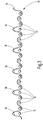
- Fig. 3 illustrates only the warp threads 12 (not all numbered) of the base fabric of a carrier part 10 carrying the adhesive elements, provided with pile threads 14 in the form of a W-bond, the pile threads 14 forming loops 16 protruding over the base fabric.
- Warp, weft and pile threads can be formed from an isotactic polypropylene, warp and weft threads preferably being multifilaments, while the pile thread 14 is preferably designed as a monofilament and has a diameter of approximately 0.20 mm.
- adhesive elements can be removed from the loops 16 of the pile thread 14 using the DE 102 40 986 B3 train known technology. If, to form the adhesive elements, the loops 16 are cut open by a thermal separation or cutting process, the free loop ends can be shrunk by further heating, the ends of which can preferably form a mushroom-like shape or also hooks.
- pole bonds in the form of a W bond with a pair of leno could be provided and / or that any suitable plastic materials are suitable in particular for the base fabric of the carrier part 10.
Description
- Die Erfindung betrifft ein mechanisches Haftverschlussteil mit den Merkmalen im Oberbegriff von Anspruch 1.
- Derartige Haftverschlussteile sind Bestandteil von Haftverschlüssen, wie sie unter der Markenbezeichnung "Kletten" weithin bekannt geworden sind. Die mit ihren Stielen mit dem Trägerteil zusammenhängenden Haftelemente bilden mit ihren Kopfteilen Verschlusskörper, die vorzugsweise die Form von Pilzköpfen, jedoch auch von Haken oder Schlaufen, haben können. Dabei sind die Haftelemente mit Stiellängen, die häufig weniger als 1mm betragen, in dichter Packung am Trägerteil derart verteilt angeordnet, dass die Verhakungskörper der Kopfteile in Verhakungseingriff mit den Gegenelementen eines den Haftverschluss vervollständigenden weiteren Haftverschlussteiles kommen.
- Eines der Kriterien für gute Gebrauchseigenschaften von Haftverschlüssen besteht darin, dass für die Betätigung des Verschlusses der Verhakungseingriff sicher und bequem erfolgen kann, selbst wenn in dem Bestreben, eine hohe Haltekraft des betätigten Verschlusses zur Verfügung zu stellen, die Haftelemente in sehr dichter Packung am Trägerteil angeordnet sind. Die Forderungen nach hoher Packungsdichte und nach einfacher Betätigbarkeit des Verschlusses mit geringem Kraftaufwand sind jedoch einander widerstrebend.
- Wenn zur Verschlussbetätigung die Haftverschlussteile aneinandergelegt werden, besteht eine gewisse Wahrscheinlichkeit, dass Kopfteile auf Kopfteile fluchtend aufeinandertreffen. Um den Verhakungseingriff zu erreichen, muss eine Art Verdrängung, um Eingriffswege frei zu machen, erfolgen. Insbesondere bei hoher Packungsdichte ist dadurch eine entsprechend hohe Betätigungskraft erforderlich. Werden hohe Betätigungskräfte in Kauf genommen, was bei bestimmten Anwendungsgebieten hingenommen werden kann, dann resultierenden vielfach im betätigten Zustand so hohe Haltekräfte, dass ein bequemes Lösen des betätigten Verschlusses erschwert oder verhindert ist.
- Im Hinblick auf diese Problematik ist es Stand der Technik, die Haftelemente am Trägerteil in einer von einer regelmäßigen Matrix abweichenden Musteranordnung vorzusehen. Diesbezüglich ist im Dokument
DE 603 10 529 T2 ein Haftverschlussteil der eingangs genannten Art offenbart, bei dem die Haftelemente in Gruppen von jeweils vier Haftelementen angeordnet sind, wobei die Haftelemente jeder Gruppe an den Ecken eines nahezu quadratischen Rechtecks angeordnet sind. - Die
DE 94 12 526 U1 zeigt Befestigungsteile auf, bei denen sich von einer Basis mit einem Kopf versehene Verankerungselemente erstrecken. Die Verankerungselemente sind in gleichmäßigen Sechsecken angeordnet, wobei innerhalb eines Sechsecks entlang einer Symmetrieachse zwei weitere Verankerungselemente vorgesehen sind. - Aus der
DE 102 40 986 B3 ist ein flächenförmiges Haftverschlussteil bekannt. Das Haftverschlussteil ist aus einem Gewebe mit Schuss- und Polfäden gebildet, wobei die Polfäden in W-förmiger Art eingebunden sind. Die Schlaufen der Polfäden sind thermisch auftrennbar und zu Pilzköpfen schrumpfbar. - Aus der
WO 94/23610 - Ausgehend von diesem Stand der Technik liegt der Erfindung die Aufgabe zugrunde, ein Haftverschlussteil zur Verfügung zu stellen, das sich durch besonders gute Gebrauchseigenschaften in Bezug auf die sichere und bequeme Betätigung mit geringem, für den Verhakungseingriff erforderlichem Kraftaufwand auszeichnet und bei dem die jeweils gewünschten Haltekräfte realisierbar sind.
- Erfindungsgemäß ist diese Aufgabe durch ein Haftverschlussteil gelöst, das die Merkmale des Patentanspruches 1 in seiner Gesamtheit aufweist.
- Demgemäß sieht die Erfindung vor, dass innerhalb der Gruppen in Form einer mehreckigen Ringanordnung mit von Haftelementen besetzten Ecken jeweils eine Haftelementgruppierung gebildet ist, deren Kopfteile in nicht betätigtem Zustand des Haftverschlusses benachbart aneinander stoßen. Eine derartige Musteranordnung, in der sowohl Gruppierungen mit kopfseitig aneinanderstoßenden Haftelementen als auch "frei stehende" Haftelemente enthalten sind, ermöglicht einen optimalen Kompromiss zwischen erforderlicher Betätigungskraft und resultierender Haltekraft, insbesondere bei der anzustrebenden hohen Packungsdichte der Haftelemente.
- Vorteilhafterweise sind die Haftelemente am Trägerteil in einer Packungsdichte von zumindest 150/cm2 angeordnet.
- Hinsichtlich der Gruppierungen mit kopfseitig aneinander stoßenden Haftelementen kann die Anordnung so getroffen sein, dass Haftelementgruppierungen durch Haftelementpaare oder aus drei Haftelemente aufweisenden Triplets gebildet sind.
- Bei aus Haftelementpaaren gebildeten Gruppierungen kann jede Gruppe vorzugsweise zumindest sechs von einem Haftelement besetzte Ecken aufweisen, wobei in jeder Gruppe die Haftelemente zumindest zweier Ecken ein Haftelementpaar mit aneinander anliegenden Kopfteilen bilden.
- Bei bevorzugten Ausführungsbeispielen weisen die Haftelemente Kopfteile in Form von Pilzköpfen auf.
- Als Werkstoff für die Haftelemente ist vorzugsweise isotaktisches Polypropylen vorgesehen.
- Bei Haftelementgruppierungen in Form von Haftelementpaaren ist die Anordnung so getroffen, dass die Gruppen der Haftelemente ungleichseitige Sechsecke mit je zwei Haftelementgruppierungen mit an ihren Kopfteilen aneinander anliegenden Haftelementpaaren bilden.
- Besonders gute Gebrauchseigenschaften werden dabei erzielt, wenn die zwischen den Haftelementpaaren der Gruppen gelegenen einzelnen Haftelemente voneinander einen größeren Abstand besitzen als von den jeweils benachbarten Haftelementpaaren.
- Entsprechend der im Dokument
DE 102 40 986 B3 aufgezeigten Technik kann das Trägerteil aus Kett-, Schuss- und Polfäden, insbesondere in Form einer W-Bindung, ausgebildet sein. Dabei werden die über das Grundgewebe vorstehenden Schlaufen der Polfäden aufgeschnitten. Die so gebildeten Fadenenden werden thermisch behandelt, um Haftelemente mit Kopfteilen in Form von Verhakungskörpern, insbesondere in Pilzkopfform, zu bilden. - Die Anordnung kann mit Vorteil so getroffen sein, dass die Kett- und Schussfäden Multifilamente sind und dass der vorzugsweise als Monofilament ausgebildete Polfaden einen Durchmesser von etwa 0,20mm aufweist.
- Bei besonders vorteilhaften Ausführungsbeispielen weisen die Kettfäden und Schussfäden 200 bzw. 110 dtex auf, wobei die Schussdichte für die Schussfäden bei etwa 23 Schuss/cm liegt.
- Nachstehend ist die Erfindung anhand von in der Zeichnung dargestellten Ausführungsbeispielen im Einzelnen erläutert. Es zeigen:
- Fig. 1
- in stark schematisch vereinfachter und stark vergrößerter, skizzenartiger Darstellung die Musteranordnung von Haftelementen gemäß einem Ausführungsbeispiel des erfindungsgemäßen Haftverschlussteiles;
- Fig. 2
- eine der
Fig. 1 entsprechende Darstellung der Musteranordnung eines nicht beanspruchten Haftverschlussteiles; und - Fig. 3
- eine schematisierte und stark vergrößerte Seitendarstellung auf eine Polbindung zur Herstellung des erfindungsgemäßen Haftverschlussteiles, wobei lediglich Pol- und Kettfäden gezeigt sind.
- Lediglich die
Fig. 1 zeigt ein erfindungsgemäßes Haftverschlussteil. Die Ausführungsform derFig. 2 dient nur zur Erläuterung des Hintergrundes der Erfindung. -
Fig. 1 verdeutlicht die Musteranordnung der Haftelemente eines Ausführungsbeispieles des erfindungsgemäßen Haftverschlussteiles. Von den Haftelementen sind inFig. 1 durch Kreise lediglich die Kopfteile 2 dargestellt, die an den Enden der nicht sichtbaren Stiele pilzkopfartige Verhakungskörper bilden. Bei dem Beispiel vonFig. 1 lässt sich die Anordnung der Haftelemente in Gruppen 4 unterteilen, die eine Ringanordnung in Form eines ungleichseitigen Sechseckes darstellen, deren sechs Ecken jeweils vom Kopfteil 2 eines Haftelementes besetzt sind. Die Sechseckform weist zueinander entgegengesetzt zwei kürzere Seiten auf, wodurch die an den Ecken dieser kurzen Seiten befindlichen Kopfteile 2 aneinander stoßen. Somit sind innerhalb jeder Gruppe 4 zwei Haftelementgruppierungen gebildet, bestehend aus je einem Haftelementpaar 6. Von diesen Haftelementpaaren 6 sind der Übersichtlichkeit halber inFig. 1 nicht sämtliche beziffert. WieFig. 1 verdeutlicht, ist eine Musteranordnung gebildet, bei der in der Folge von sich in der Fig. waagerecht erstreckenden Gruppen 4 sich Gruppierungen, die aus Haftelementpaaren 6 gebildet sind, mit einzelnen Kopfteilen 2 abwechseln, wobei die nicht zu Paaren 6 gehörenden Kopfteile 2 voneinander einen größeren Abstand besitzen als von den jeweils benachbarten Paaren 6. Wie sich gezeigt hat, bietet eine derartige Musteranordnung, bei der sich "frei stehende" Kopfteile 2 in der gezeigten Weise mit Gruppierungen abwechseln, die durch kopfseitig aneinander stoßende Haftelementpaare 6 gebildet sind, beste Verhältnisse hinsichtlich der Verschlussbetätigung durch Herbeiführen des Verhakungseingriffes mit verhältnismäßig geringem Kraftaufwand, und zwar trotz einer Anordnung der Haftelemente in hoher Packungsdichte von beispielsweise mehr als 150 Haftelementen pro cm2. Bei einer derartigen Musteranordnung sind auch die für die Gebrauchseigenschaften günstigen Haltekräfte realisierbar. -
Fig. 2 verdeutlicht ein nicht beanspruchtes Haftverschlussteil, bei dem wiederum Gruppen 4 eine Ringanordnung in Form eines ungleichseitigen Sechseckes definieren, dessen Ecken jeweils von einem Kopfteil 2 eines betreffenden Haftelementes besetzt sind. Bei der Rechteckform vonFig. 2 sind zwei lange Seiten einander gegenüberliegend, während zwischen den langen Seiten beidseits zwei kurze Seiten vorgesehen sind. Wiederum ist jede Ecke vom Kopfteil 2 eines Haftelementes besetzt. Entsprechend dem verringerten Abstand der Ecken an den vier kürzeren Seiten ist an den durch die langen Seiten getrennten drei Ecken jeweils eine Gruppierung in Form eines Triplets oder einer Dreiergruppe von Haftelementen gebildet, bei denen drei Kopfteile 2 in Aufeinanderfolge aneinander stoßen. Somit sind bei diesem Ausführungsbeispiel abwechselnde Reihen 8 aus dicht gepackten Kopfteilen 2 gebildet, die mit Freiräume bildenden Reihen abwechseln. Je nach Wahl der Länge der zwei langen Seiten der Sechseckform und damit der Weite der zwischen den Reihen 8 gebildeten Freiräume lassen sich die Eigenschaften des Verschlusses hinsichtlich Haltekraft und Betätigungskraft optimieren. -
Fig. 3 verdeutlicht vom Grundgewebe eines die Haftelemente tragenden Trägerteiles 10 lediglich Kettfäden 12 (nicht sämtliche beziffert), versehen mit Polfäden 14 in Form einer W-Bindung, wobei die Polfäden 14 über das Grundgewebe vorstehende Schlaufen 16 bilden. Kett-, Schussfäden und Polfäden können aus einem isotaktischen Polypropylen gebildet sein, wobei Kett- und Schussfäden vorzugsweise Multifilamente sind, während der Polfaden 14 vorzugsweise als Monofilament ausgebildet ist und einen Durchmesser von etwa 0,20mm aufweist. Bei derartigen Werkstoffen lassen sich aus den Schlaufen 16 des Polfadens 14 Haftelemente mittels der ausDE 102 40 986 B3 bekannten Technik ausbilden. Wenn zur Bildung der Haftelemente die Schlaufen 16 durch einen thermischen Trenn- oder Schneidvorgang aufgeschnitten werden, können die freien Schlaufenenden durch weiteres Erhitzen zum Schrumpfen gebracht werden, wobei die Enden Verschlusskörper vorzugsweise pilzartiger Form oder auch Verschlusshaken bilden können. - Bei Durchmessern des Polfadens 14 von etwa 0,20mm und bei Kettfäden und Schussfäden, die 200 bzw. 110dtex aufweisen, lassen sich Packungsdichten der gebildeten Haftelemente von mehr als 150/cm2 verwirklichen. Die Schussdichte für die in
Fig. 3 nicht gezeigten Schussfäden kann im Bereich von 23 Schuss/cm liegen. - Es versteht sich, dass anstelle von Polbindungen in Form einer W-Bindung mit einem Dreherpaar andere Bindungsarten vorgesehen sein könnten und/oder dass insbesondere für das Grundgewebe des Trägerteiles 10 beliebige, geeignete Kunststoffwerkstoffe in Frage kommen.
Claims (9)
- Mechanisches Haftverschlussteil, mit einem Trägerteil (10) und einer Vielzahl von Haftelementen, die sich über Stiele vom Trägerteil (10) weg erstrecken und an ihrem freien Ende jeweils mit einem Kopfteil (2) versehen sind, wobei die Haftelemente auf dem Trägerteil (10) in Gruppen (4) unterteilbar angeordnet sind, die eine fiktive Ringanordnung in Form eines Mehreckes mit von einem Haftelement besetzten Ecken bilden, wobei innerhalb der jeweiligen Gruppen (4) eine Haftelementgruppierung (6) gebildet ist, deren Kopfteile (2) in nicht betätigtem Zustand des Haftverschlusses benachbart aneinander stoßen und wobei die Gruppen (4) der Haftelemente ungleichseitige Sechsecke mit je zwei Haftelementgruppierungen mit an ihren Kopfteilen (2) aneinander anliegenden Haftelementpaaren (6) bilden, dadurch gekennzeichnet, dass die zwischen den Haftelementpaaren (6) der Gruppen (4) gelegenen einzelnen Haftelemente voneinander einen größeren Abstand besitzen als von den jeweils benachbarten Haftelementpaaren (6).
- Haftverschlussteil nach Anspruch 1, dadurch gekennzeichnet, dass die Haftelemente am Trägerteil (10) in einer Packungsdichte von zumindest 150/cm2 angeordnet sind.
- Haftverschlussteil nach Anspruch 1 oder 2, dadurch gekennzeichnet, dass die Haftelementgruppierungen durch Haftelementpaare (6) oder aus drei Haftelemente aufweisenden Triplets gebildet sind.
- Haftverschlussteil nach Anspruch 3, dadurch gekennzeichnet, dass jede Gruppe (4) zumindest sechs von einem Haftelement besetzte Ecken aufweist und dass in jeder Gruppe (4) die Haftelemente zumindest zweier Ecken ein Haftelementpaar (6) mit aneinander anliegenden Kopfteilen (2) bilden.
- Haftverschlussteil nach einem der Ansprüche 1 bis 4, dadurch gekennzeichnet, dass Haftelemente mit Kopfteilen (2) in Form von Pilzköpfen vorgesehen sind.
- Haftverschlussteil nach einem der Ansprüche 1 bis 5, dadurch gekennzeichnet, dass die Haftelemente aus isotaktischem Polypropylen gebildet sind.
- Haftverschlussteil nach einem der Ansprüche 1 bis 6, dadurch gekennzeichnet, dass das Trägerteil (10) aus Kett- (12), Schuss- und Polfäden (14), insbesondere in Form einer W-Bindung, ausgebildet ist, wobei die über das Grundgewebe vorstehenden Schlaufen der Polfäden (14) aufgeschnitten und die so gebildeten Fadenenden thermisch behandelt sind, um Haftelemente mit Kopfteilen (2) in Form von Verhakungskörpern zu bilden.
- Haftverschlussteil nach Anspruch 7, dadurch gekennzeichnet, dass die Kett- (12) und Schussfäden Multifilamente sind und dass der vorzugsweise als Monofilament ausgebildete Polfaden (14) einen Durchmesser von etwa 0,20 mm aufweist.
- Haftverschlussteil nach Anspruch 7 oder 8, dadurch gekennzeichnet, dass die Kettfäden (12) und Schussfäden 200 bzw. 110 dtex aufweisen und dass die Schussdichte für die Schussfäden bei etwa 23 Schuss/cm liegt.
Priority Applications (1)
| Application Number | Priority Date | Filing Date | Title |
|---|---|---|---|
| PL10718889T PL2429327T3 (pl) | 2009-05-13 | 2010-05-04 | Mechaniczna część zapięcia przyczepnego |
Applications Claiming Priority (2)
| Application Number | Priority Date | Filing Date | Title |
|---|---|---|---|
| DE102009021094A DE102009021094A1 (de) | 2009-05-13 | 2009-05-13 | Mechanisches Haftverschlussteil |
| PCT/EP2010/002704 WO2011100999A1 (de) | 2009-05-13 | 2010-05-04 | Mechanisches haftverschlussteil |
Publications (2)
| Publication Number | Publication Date |
|---|---|
| EP2429327A1 EP2429327A1 (de) | 2012-03-21 |
| EP2429327B1 true EP2429327B1 (de) | 2020-07-08 |
Family
ID=42733790
Family Applications (1)
| Application Number | Title | Priority Date | Filing Date |
|---|---|---|---|
| EP10718889.8A Active EP2429327B1 (de) | 2009-05-13 | 2010-05-04 | Mechanisches haftverschlussteil |
Country Status (8)
| Country | Link |
|---|---|
| US (1) | US8776331B2 (de) |
| EP (1) | EP2429327B1 (de) |
| JP (1) | JP5584755B2 (de) |
| CN (1) | CN102421319B (de) |
| DE (1) | DE102009021094A1 (de) |
| ES (1) | ES2820307T3 (de) |
| PL (1) | PL2429327T3 (de) |
| WO (1) | WO2011100999A1 (de) |
Families Citing this family (3)
| Publication number | Priority date | Publication date | Assignee | Title |
|---|---|---|---|---|
| WO2017216881A1 (ja) * | 2016-06-14 | 2017-12-21 | Ykk株式会社 | ファスニング具、及びファスニング具の組 |
| US10349707B2 (en) | 2016-07-05 | 2019-07-16 | Alfatex Nv | Fastener tape |
| FR3116419A1 (fr) | 2020-11-23 | 2022-05-27 | Aplix | Dispositif de retenue amélioré pour la protection d’éléments de retenue |
Family Cites Families (16)
| Publication number | Priority date | Publication date | Assignee | Title |
|---|---|---|---|---|
| US3320649A (en) * | 1962-10-23 | 1967-05-23 | Naimer Jack | Methods of making separable fastening fabrics |
| US5852855A (en) * | 1989-11-17 | 1998-12-29 | Minnesota Mining And Manufacturing Company | Disposable diaper with fastener |
| US5679302A (en) | 1990-09-21 | 1997-10-21 | Minnesota Mining And Manufacturing Company | Method for making a mushroom-type hook strip for a mechanical fastener |
| JPH04338402A (ja) * | 1991-05-16 | 1992-11-25 | Dynic Corp | 雄面ファスナーおよびその製法 |
| JPH0723810A (ja) * | 1993-04-08 | 1995-01-27 | Majitsuku Tape Kk | 面ファスナー部材 |
| JP3476867B2 (ja) * | 1993-08-05 | 2003-12-10 | ミネソタ マイニング アンド マニュファクチャリング カンパニー | 対面係合ファスナー部材 |
| US5457855A (en) * | 1994-02-28 | 1995-10-17 | Velcro Industries, B.V. | Woven self-engaging fastener |
| JP2828593B2 (ja) * | 1994-04-22 | 1998-11-25 | ワイケイケイ株式会社 | 厚手基布を有する面ファスナー |
| US5813095A (en) * | 1996-12-09 | 1998-09-29 | Robertson; Thomas Wilson | Re-closable surface binding method |
| US6159596A (en) * | 1997-12-23 | 2000-12-12 | 3M Innovative Properties Company | Self mating adhesive fastener element articles including a self mating adhesive fastener element and methods for producing and using |
| US6687962B2 (en) | 2002-01-16 | 2004-02-10 | Velcro Industries B.V. | Fastener element patterning |
| DE10240986B3 (de) | 2002-09-05 | 2004-02-12 | Gottlieb Binder Gmbh & Co | Flächenförmiges Haftverschlußteil |
| US7067185B2 (en) * | 2003-06-11 | 2006-06-27 | 3M Innovative Properties Company | Reinforced hook web |
| ATE373555T1 (de) * | 2004-03-18 | 2007-10-15 | Velcro Ind | Übertragung von harz zum formen von befestigungselementen |
| DE102004053469A1 (de) * | 2004-11-03 | 2006-05-04 | Paul Hartmann Ag | Schlaufenbildendes Vliesstoffmaterial für ein mechanisches Verschlussmittel |
| DE102006039579A1 (de) * | 2006-08-23 | 2008-03-13 | Gottlieb Binder Gmbh & Co. Kg | Festlegesystem und dafür verwendbares Befestigungselement |
-
2009
- 2009-05-13 DE DE102009021094A patent/DE102009021094A1/de not_active Withdrawn
-
2010
- 2010-05-04 EP EP10718889.8A patent/EP2429327B1/de active Active
- 2010-05-04 US US13/138,981 patent/US8776331B2/en active Active
- 2010-05-04 PL PL10718889T patent/PL2429327T3/pl unknown
- 2010-05-04 CN CN201080020609.5A patent/CN102421319B/zh active Active
- 2010-05-04 JP JP2012510139A patent/JP5584755B2/ja active Active
- 2010-05-04 ES ES10718889T patent/ES2820307T3/es active Active
- 2010-05-04 WO PCT/EP2010/002704 patent/WO2011100999A1/de active Application Filing
Non-Patent Citations (1)
| Title |
|---|
| None * |
Also Published As
| Publication number | Publication date |
|---|---|
| WO2011100999A1 (de) | 2011-08-25 |
| ES2820307T3 (es) | 2021-04-20 |
| US8776331B2 (en) | 2014-07-15 |
| CN102421319B (zh) | 2015-09-02 |
| DE102009021094A1 (de) | 2010-11-18 |
| EP2429327A1 (de) | 2012-03-21 |
| JP2012526567A (ja) | 2012-11-01 |
| US20120047694A1 (en) | 2012-03-01 |
| PL2429327T3 (pl) | 2020-11-30 |
| CN102421319A (zh) | 2012-04-18 |
| JP5584755B2 (ja) | 2014-09-03 |
Similar Documents
| Publication | Publication Date | Title |
|---|---|---|
| DE19801278C2 (de) | Gegossenes Eingriffsteil für einen Flächenhaftverschluß | |
| DE60310529T2 (de) | Verschlusselementmusterung | |
| DE102007020608B4 (de) | Federelement für Polster | |
| DE2112238A1 (de) | Flaechenhaftverschluss | |
| DE60109873T2 (de) | Klettverschluss mit magnetisch anziehbaren Elementen | |
| EP1787551A1 (de) | Federkern | |
| DE202012103711U1 (de) | Trägerplatte eines Werkstückträgersystems sowie Werkstückträgersystem | |
| DE112017000701T5 (de) | Verschlussband | |
| EP2429327B1 (de) | Mechanisches haftverschlussteil | |
| EP3815514A1 (de) | Matte sowie aus der matte gebildete wuchshilfe und/oder schutz für pflanzen in form einer hülle | |
| EP0955515A1 (de) | Gewebe, insbesondere Stichschutzgewebe | |
| DE102012109184A1 (de) | Trägerplatte eines Werkstückträgersystems sowie Werkstückträgersystem | |
| EP3694368B1 (de) | Haftverschlusssystem | |
| DE202009006743U1 (de) | Matratze für Liegemöbel | |
| EP0559068A1 (de) | Netz, insbesondere Abstandshalternetz, Oberflächenschutznetz oder dergleichen | |
| EP0565750A1 (de) | Haftverschlussteil und von diesem gebildete Haftverbindung | |
| DE202020100391U1 (de) | Pflanzentopfhalter | |
| DE10325723B3 (de) | Verfahren und Vorrichtung zum schrittweisen Aufbau eines Einbauelements für einen Wärmetauscher, insbesondere für einen Kühlturm | |
| DE3022032C2 (de) | Reißverschluß mit gewebten Tragbändern und darin eingewebten Verschlußgliedern aus Kunststoffmonofilament | |
| EP0192220B1 (de) | Stabilisierungsvorrichtung für eine Mehrzahl von gereiht und parallel zueinander aufgestellten Glasscheiben | |
| DE102010060472B4 (de) | Federkern | |
| DE112021001557T5 (de) | Sitz | |
| DE102004025335B4 (de) | Einbauelement und dessen Verwendung zum Einbau in einen Hohlraum | |
| EP3971924A1 (de) | Elektroisolierleistengitter | |
| DE2258526C3 (de) | Käsehorde |
Legal Events
| Date | Code | Title | Description |
|---|---|---|---|
| PUAI | Public reference made under article 153(3) epc to a published international application that has entered the european phase |
Free format text: ORIGINAL CODE: 0009012 |
|
| 17P | Request for examination filed |
Effective date: 20111006 |
|
| AK | Designated contracting states |
Kind code of ref document: A1 Designated state(s): AL AT BE BG CH CY CZ DE DK EE ES FI FR GB GR HR HU IE IS IT LI LT LU LV MC MK MT NL NO PL PT RO SE SI SK SM TR |
|
| DAX | Request for extension of the european patent (deleted) | ||
| STAA | Information on the status of an ep patent application or granted ep patent |
Free format text: STATUS: EXAMINATION IS IN PROGRESS |
|
| 17Q | First examination report despatched |
Effective date: 20180329 |
|
| GRAP | Despatch of communication of intention to grant a patent |
Free format text: ORIGINAL CODE: EPIDOSNIGR1 |
|
| STAA | Information on the status of an ep patent application or granted ep patent |
Free format text: STATUS: GRANT OF PATENT IS INTENDED |
|
| INTG | Intention to grant announced |
Effective date: 20200221 |
|
| GRAS | Grant fee paid |
Free format text: ORIGINAL CODE: EPIDOSNIGR3 |
|
| GRAA | (expected) grant |
Free format text: ORIGINAL CODE: 0009210 |
|
| STAA | Information on the status of an ep patent application or granted ep patent |
Free format text: STATUS: THE PATENT HAS BEEN GRANTED |
|
| AK | Designated contracting states |
Kind code of ref document: B1 Designated state(s): AL AT BE BG CH CY CZ DE DK EE ES FI FR GB GR HR HU IE IS IT LI LT LU LV MC MK MT NL NO PL PT RO SE SI SK SM TR |
|
| REG | Reference to a national code |
Ref country code: GB Ref legal event code: FG4D Free format text: NOT ENGLISH |
|
| REG | Reference to a national code |
Ref country code: CH Ref legal event code: EP Ref country code: CH Ref legal event code: NV Representative=s name: ISLER AND PEDRAZZINI AG, CH Ref country code: AT Ref legal event code: REF Ref document number: 1287498 Country of ref document: AT Kind code of ref document: T Effective date: 20200715 |
|
| REG | Reference to a national code |
Ref country code: DE Ref legal event code: R096 Ref document number: 502010016685 Country of ref document: DE |
|
| REG | Reference to a national code |
Ref country code: IE Ref legal event code: FG4D Free format text: LANGUAGE OF EP DOCUMENT: GERMAN |
|
| REG | Reference to a national code |
Ref country code: NL Ref legal event code: FP |
|
| REG | Reference to a national code |
Ref country code: LT Ref legal event code: MG4D |
|
| PG25 | Lapsed in a contracting state [announced via postgrant information from national office to epo] |
Ref country code: GR Free format text: LAPSE BECAUSE OF FAILURE TO SUBMIT A TRANSLATION OF THE DESCRIPTION OR TO PAY THE FEE WITHIN THE PRESCRIBED TIME-LIMIT Effective date: 20201009 Ref country code: NO Free format text: LAPSE BECAUSE OF FAILURE TO SUBMIT A TRANSLATION OF THE DESCRIPTION OR TO PAY THE FEE WITHIN THE PRESCRIBED TIME-LIMIT Effective date: 20201008 Ref country code: HR Free format text: LAPSE BECAUSE OF FAILURE TO SUBMIT A TRANSLATION OF THE DESCRIPTION OR TO PAY THE FEE WITHIN THE PRESCRIBED TIME-LIMIT Effective date: 20200708 Ref country code: SE Free format text: LAPSE BECAUSE OF FAILURE TO SUBMIT A TRANSLATION OF THE DESCRIPTION OR TO PAY THE FEE WITHIN THE PRESCRIBED TIME-LIMIT Effective date: 20200708 Ref country code: FI Free format text: LAPSE BECAUSE OF FAILURE TO SUBMIT A TRANSLATION OF THE DESCRIPTION OR TO PAY THE FEE WITHIN THE PRESCRIBED TIME-LIMIT Effective date: 20200708 Ref country code: PT Free format text: LAPSE BECAUSE OF FAILURE TO SUBMIT A TRANSLATION OF THE DESCRIPTION OR TO PAY THE FEE WITHIN THE PRESCRIBED TIME-LIMIT Effective date: 20201109 Ref country code: LT Free format text: LAPSE BECAUSE OF FAILURE TO SUBMIT A TRANSLATION OF THE DESCRIPTION OR TO PAY THE FEE WITHIN THE PRESCRIBED TIME-LIMIT Effective date: 20200708 Ref country code: BG Free format text: LAPSE BECAUSE OF FAILURE TO SUBMIT A TRANSLATION OF THE DESCRIPTION OR TO PAY THE FEE WITHIN THE PRESCRIBED TIME-LIMIT Effective date: 20201008 |
|
| PG25 | Lapsed in a contracting state [announced via postgrant information from national office to epo] |
Ref country code: LV Free format text: LAPSE BECAUSE OF FAILURE TO SUBMIT A TRANSLATION OF THE DESCRIPTION OR TO PAY THE FEE WITHIN THE PRESCRIBED TIME-LIMIT Effective date: 20200708 Ref country code: IS Free format text: LAPSE BECAUSE OF FAILURE TO SUBMIT A TRANSLATION OF THE DESCRIPTION OR TO PAY THE FEE WITHIN THE PRESCRIBED TIME-LIMIT Effective date: 20201108 |
|
| REG | Reference to a national code |
Ref country code: DE Ref legal event code: R097 Ref document number: 502010016685 Country of ref document: DE |
|
| REG | Reference to a national code |
Ref country code: ES Ref legal event code: FG2A Ref document number: 2820307 Country of ref document: ES Kind code of ref document: T3 Effective date: 20210420 |
|
| PG25 | Lapsed in a contracting state [announced via postgrant information from national office to epo] |
Ref country code: SM Free format text: LAPSE BECAUSE OF FAILURE TO SUBMIT A TRANSLATION OF THE DESCRIPTION OR TO PAY THE FEE WITHIN THE PRESCRIBED TIME-LIMIT Effective date: 20200708 Ref country code: RO Free format text: LAPSE BECAUSE OF FAILURE TO SUBMIT A TRANSLATION OF THE DESCRIPTION OR TO PAY THE FEE WITHIN THE PRESCRIBED TIME-LIMIT Effective date: 20200708 Ref country code: EE Free format text: LAPSE BECAUSE OF FAILURE TO SUBMIT A TRANSLATION OF THE DESCRIPTION OR TO PAY THE FEE WITHIN THE PRESCRIBED TIME-LIMIT Effective date: 20200708 Ref country code: CZ Free format text: LAPSE BECAUSE OF FAILURE TO SUBMIT A TRANSLATION OF THE DESCRIPTION OR TO PAY THE FEE WITHIN THE PRESCRIBED TIME-LIMIT Effective date: 20200708 Ref country code: DK Free format text: LAPSE BECAUSE OF FAILURE TO SUBMIT A TRANSLATION OF THE DESCRIPTION OR TO PAY THE FEE WITHIN THE PRESCRIBED TIME-LIMIT Effective date: 20200708 |
|
| PLBE | No opposition filed within time limit |
Free format text: ORIGINAL CODE: 0009261 |
|
| STAA | Information on the status of an ep patent application or granted ep patent |
Free format text: STATUS: NO OPPOSITION FILED WITHIN TIME LIMIT |
|
| PG25 | Lapsed in a contracting state [announced via postgrant information from national office to epo] |
Ref country code: AL Free format text: LAPSE BECAUSE OF FAILURE TO SUBMIT A TRANSLATION OF THE DESCRIPTION OR TO PAY THE FEE WITHIN THE PRESCRIBED TIME-LIMIT Effective date: 20200708 |
|
| 26N | No opposition filed |
Effective date: 20210409 |
|
| PG25 | Lapsed in a contracting state [announced via postgrant information from national office to epo] |
Ref country code: SK Free format text: LAPSE BECAUSE OF FAILURE TO SUBMIT A TRANSLATION OF THE DESCRIPTION OR TO PAY THE FEE WITHIN THE PRESCRIBED TIME-LIMIT Effective date: 20200708 |
|
| PG25 | Lapsed in a contracting state [announced via postgrant information from national office to epo] |
Ref country code: SI Free format text: LAPSE BECAUSE OF FAILURE TO SUBMIT A TRANSLATION OF THE DESCRIPTION OR TO PAY THE FEE WITHIN THE PRESCRIBED TIME-LIMIT Effective date: 20200708 |
|
| PG25 | Lapsed in a contracting state [announced via postgrant information from national office to epo] |
Ref country code: LU Free format text: LAPSE BECAUSE OF NON-PAYMENT OF DUE FEES Effective date: 20210504 Ref country code: MC Free format text: LAPSE BECAUSE OF FAILURE TO SUBMIT A TRANSLATION OF THE DESCRIPTION OR TO PAY THE FEE WITHIN THE PRESCRIBED TIME-LIMIT Effective date: 20200708 |
|
| PG25 | Lapsed in a contracting state [announced via postgrant information from national office to epo] |
Ref country code: IE Free format text: LAPSE BECAUSE OF NON-PAYMENT OF DUE FEES Effective date: 20210504 |
|
| PGFP | Annual fee paid to national office [announced via postgrant information from national office to epo] |
Ref country code: PL Payment date: 20220315 Year of fee payment: 13 |
|
| PGFP | Annual fee paid to national office [announced via postgrant information from national office to epo] |
Ref country code: IT Payment date: 20220511 Year of fee payment: 13 |
|
| PGFP | Annual fee paid to national office [announced via postgrant information from national office to epo] |
Ref country code: CH Payment date: 20220512 Year of fee payment: 13 Ref country code: BE Payment date: 20220413 Year of fee payment: 13 Ref country code: AT Payment date: 20220518 Year of fee payment: 13 |
|
| REG | Reference to a national code |
Ref country code: DE Ref legal event code: R082 Ref document number: 502010016685 Country of ref document: DE Representative=s name: KOHLER SCHMID MOEBUS PATENTANWAELTE PARTNERSCH, DE Ref country code: DE Ref legal event code: R082 Ref document number: 502010016685 Country of ref document: DE |
|
| PG25 | Lapsed in a contracting state [announced via postgrant information from national office to epo] |
Ref country code: HU Free format text: LAPSE BECAUSE OF FAILURE TO SUBMIT A TRANSLATION OF THE DESCRIPTION OR TO PAY THE FEE WITHIN THE PRESCRIBED TIME-LIMIT; INVALID AB INITIO Effective date: 20100504 Ref country code: CY Free format text: LAPSE BECAUSE OF FAILURE TO SUBMIT A TRANSLATION OF THE DESCRIPTION OR TO PAY THE FEE WITHIN THE PRESCRIBED TIME-LIMIT Effective date: 20200708 |
|
| REG | Reference to a national code |
Ref country code: DE Ref legal event code: R082 Ref document number: 502010016685 Country of ref document: DE Representative=s name: KOHLER SCHMID MOEBUS PATENTANWAELTE PARTNERSCH, DE |
|
| PGFP | Annual fee paid to national office [announced via postgrant information from national office to epo] |
Ref country code: NL Payment date: 20230519 Year of fee payment: 14 Ref country code: FR Payment date: 20230517 Year of fee payment: 14 Ref country code: ES Payment date: 20230621 Year of fee payment: 14 Ref country code: DE Payment date: 20230525 Year of fee payment: 14 |
|
| PGFP | Annual fee paid to national office [announced via postgrant information from national office to epo] |
Ref country code: TR Payment date: 20230523 Year of fee payment: 14 |
|
| PGFP | Annual fee paid to national office [announced via postgrant information from national office to epo] |
Ref country code: GB Payment date: 20230522 Year of fee payment: 14 |
|
| REG | Reference to a national code |
Ref country code: CH Ref legal event code: PL |
|
| REG | Reference to a national code |
Ref country code: AT Ref legal event code: MM01 Ref document number: 1287498 Country of ref document: AT Kind code of ref document: T Effective date: 20230504 |
|
| REG | Reference to a national code |
Ref country code: BE Ref legal event code: MM Effective date: 20230531 |
|
| PG25 | Lapsed in a contracting state [announced via postgrant information from national office to epo] |
Ref country code: LI Free format text: LAPSE BECAUSE OF NON-PAYMENT OF DUE FEES Effective date: 20230531 Ref country code: CH Free format text: LAPSE BECAUSE OF NON-PAYMENT OF DUE FEES Effective date: 20230531 Ref country code: AT Free format text: LAPSE BECAUSE OF NON-PAYMENT OF DUE FEES Effective date: 20230504 |