EP2426328B1 - Dispositif de purification de gaz d'échappement de moteur - Google Patents
Dispositif de purification de gaz d'échappement de moteur Download PDFInfo
- Publication number
- EP2426328B1 EP2426328B1 EP11191519.5A EP11191519A EP2426328B1 EP 2426328 B1 EP2426328 B1 EP 2426328B1 EP 11191519 A EP11191519 A EP 11191519A EP 2426328 B1 EP2426328 B1 EP 2426328B1
- Authority
- EP
- European Patent Office
- Prior art keywords
- temperature
- reducing agent
- storage tank
- engine
- heating medium
- Prior art date
- Legal status (The legal status is an assumption and is not a legal conclusion. Google has not performed a legal analysis and makes no representation as to the accuracy of the status listed.)
- Expired - Lifetime
Links
- 238000000746 purification Methods 0.000 title description 4
- MWUXSHHQAYIFBG-UHFFFAOYSA-N nitrogen oxide Inorganic materials O=[N] MWUXSHHQAYIFBG-UHFFFAOYSA-N 0.000 claims description 100
- 239000003054 catalyst Substances 0.000 claims description 93
- 239000003638 chemical reducing agent Substances 0.000 claims description 66
- 238000010438 heat treatment Methods 0.000 claims description 35
- 230000000903 blocking effect Effects 0.000 claims description 15
- 238000007710 freezing Methods 0.000 claims description 5
- 230000008014 freezing Effects 0.000 claims description 5
- QGZKDVFQNNGYKY-UHFFFAOYSA-N Ammonia Chemical compound N QGZKDVFQNNGYKY-UHFFFAOYSA-N 0.000 description 79
- 230000003647 oxidation Effects 0.000 description 40
- 238000007254 oxidation reaction Methods 0.000 description 40
- 239000000498 cooling water Substances 0.000 description 39
- WTHDKMILWLGDKL-UHFFFAOYSA-N urea;hydrate Chemical compound O.NC(N)=O WTHDKMILWLGDKL-UHFFFAOYSA-N 0.000 description 37
- 239000007789 gas Substances 0.000 description 36
- 238000006722 reduction reaction Methods 0.000 description 35
- 229910021529 ammonia Inorganic materials 0.000 description 28
- XSQUKJJJFZCRTK-UHFFFAOYSA-N Urea Chemical compound NC(N)=O XSQUKJJJFZCRTK-UHFFFAOYSA-N 0.000 description 22
- 239000004202 carbamide Substances 0.000 description 22
- 239000000243 solution Substances 0.000 description 21
- 238000002347 injection Methods 0.000 description 16
- 239000007924 injection Substances 0.000 description 16
- 238000011144 upstream manufacturing Methods 0.000 description 12
- 230000003213 activating effect Effects 0.000 description 7
- 238000010586 diagram Methods 0.000 description 4
- 238000007599 discharging Methods 0.000 description 4
- 239000007788 liquid Substances 0.000 description 4
- 230000001681 protective effect Effects 0.000 description 4
- 239000004215 Carbon black (E152) Substances 0.000 description 3
- 239000002283 diesel fuel Substances 0.000 description 3
- 229930195733 hydrocarbon Natural products 0.000 description 3
- 150000002430 hydrocarbons Chemical class 0.000 description 3
- 239000000126 substance Substances 0.000 description 3
- XLYOFNOQVPJJNP-UHFFFAOYSA-N water Chemical compound O XLYOFNOQVPJJNP-UHFFFAOYSA-N 0.000 description 3
- MGWGWNFMUOTEHG-UHFFFAOYSA-N 4-(3,5-dimethylphenyl)-1,3-thiazol-2-amine Chemical compound CC1=CC(C)=CC(C=2N=C(N)SC=2)=C1 MGWGWNFMUOTEHG-UHFFFAOYSA-N 0.000 description 2
- NLXLAEXVIDQMFP-UHFFFAOYSA-N Ammonium chloride Substances [NH4+].[Cl-] NLXLAEXVIDQMFP-UHFFFAOYSA-N 0.000 description 2
- VHUUQVKOLVNVRT-UHFFFAOYSA-N Ammonium hydroxide Chemical compound [NH4+].[OH-] VHUUQVKOLVNVRT-UHFFFAOYSA-N 0.000 description 2
- OKTJSMMVPCPJKN-UHFFFAOYSA-N Carbon Chemical compound [C] OKTJSMMVPCPJKN-UHFFFAOYSA-N 0.000 description 2
- 235000011114 ammonium hydroxide Nutrition 0.000 description 2
- 239000000446 fuel Substances 0.000 description 2
- 229910052680 mordenite Inorganic materials 0.000 description 2
- JCXJVPUVTGWSNB-UHFFFAOYSA-N nitrogen dioxide Inorganic materials O=[N]=O JCXJVPUVTGWSNB-UHFFFAOYSA-N 0.000 description 2
- 230000001590 oxidative effect Effects 0.000 description 2
- 230000004913 activation Effects 0.000 description 1
- 239000007864 aqueous solution Substances 0.000 description 1
- 230000015556 catabolic process Effects 0.000 description 1
- 230000003197 catalytic effect Effects 0.000 description 1
- 238000010531 catalytic reduction reaction Methods 0.000 description 1
- 238000006243 chemical reaction Methods 0.000 description 1
- 239000003795 chemical substances by application Substances 0.000 description 1
- 239000011248 coating agent Substances 0.000 description 1
- 238000000576 coating method Methods 0.000 description 1
- 238000001816 cooling Methods 0.000 description 1
- 230000003247 decreasing effect Effects 0.000 description 1
- 238000006731 degradation reaction Methods 0.000 description 1
- 230000001419 dependent effect Effects 0.000 description 1
- 230000000694 effects Effects 0.000 description 1
- 238000005516 engineering process Methods 0.000 description 1
- 230000007062 hydrolysis Effects 0.000 description 1
- 238000006460 hydrolysis reaction Methods 0.000 description 1
- 238000004519 manufacturing process Methods 0.000 description 1
- 239000002184 metal Substances 0.000 description 1
- 239000000203 mixture Substances 0.000 description 1
- 230000002265 prevention Effects 0.000 description 1
- 230000009257 reactivity Effects 0.000 description 1
Images


Classifications
-
- F—MECHANICAL ENGINEERING; LIGHTING; HEATING; WEAPONS; BLASTING
- F01—MACHINES OR ENGINES IN GENERAL; ENGINE PLANTS IN GENERAL; STEAM ENGINES
- F01N—GAS-FLOW SILENCERS OR EXHAUST APPARATUS FOR MACHINES OR ENGINES IN GENERAL; GAS-FLOW SILENCERS OR EXHAUST APPARATUS FOR INTERNAL COMBUSTION ENGINES
- F01N3/00—Exhaust or silencing apparatus having means for purifying, rendering innocuous, or otherwise treating exhaust
- F01N3/08—Exhaust or silencing apparatus having means for purifying, rendering innocuous, or otherwise treating exhaust for rendering innocuous
- F01N3/10—Exhaust or silencing apparatus having means for purifying, rendering innocuous, or otherwise treating exhaust for rendering innocuous by thermal or catalytic conversion of noxious components of exhaust
- F01N3/18—Exhaust or silencing apparatus having means for purifying, rendering innocuous, or otherwise treating exhaust for rendering innocuous by thermal or catalytic conversion of noxious components of exhaust characterised by methods of operation; Control
- F01N3/20—Exhaust or silencing apparatus having means for purifying, rendering innocuous, or otherwise treating exhaust for rendering innocuous by thermal or catalytic conversion of noxious components of exhaust characterised by methods of operation; Control specially adapted for catalytic conversion ; Methods of operation or control of catalytic converters
- F01N3/2066—Selective catalytic reduction [SCR]
- F01N3/208—Control of selective catalytic reduction [SCR], e.g. dosing of reducing agent
-
- B—PERFORMING OPERATIONS; TRANSPORTING
- B01—PHYSICAL OR CHEMICAL PROCESSES OR APPARATUS IN GENERAL
- B01D—SEPARATION
- B01D53/00—Separation of gases or vapours; Recovering vapours of volatile solvents from gases; Chemical or biological purification of waste gases, e.g. engine exhaust gases, smoke, fumes, flue gases, aerosols
- B01D53/34—Chemical or biological purification of waste gases
- B01D53/92—Chemical or biological purification of waste gases of engine exhaust gases
- B01D53/94—Chemical or biological purification of waste gases of engine exhaust gases by catalytic processes
- B01D53/9404—Removing only nitrogen compounds
- B01D53/9409—Nitrogen oxides
-
- F—MECHANICAL ENGINEERING; LIGHTING; HEATING; WEAPONS; BLASTING
- F01—MACHINES OR ENGINES IN GENERAL; ENGINE PLANTS IN GENERAL; STEAM ENGINES
- F01N—GAS-FLOW SILENCERS OR EXHAUST APPARATUS FOR MACHINES OR ENGINES IN GENERAL; GAS-FLOW SILENCERS OR EXHAUST APPARATUS FOR INTERNAL COMBUSTION ENGINES
- F01N11/00—Monitoring or diagnostic devices for exhaust-gas treatment apparatus, e.g. for catalytic activity
- F01N11/002—Monitoring or diagnostic devices for exhaust-gas treatment apparatus, e.g. for catalytic activity the diagnostic devices measuring or estimating temperature or pressure in, or downstream of the exhaust apparatus
-
- F—MECHANICAL ENGINEERING; LIGHTING; HEATING; WEAPONS; BLASTING
- F01—MACHINES OR ENGINES IN GENERAL; ENGINE PLANTS IN GENERAL; STEAM ENGINES
- F01N—GAS-FLOW SILENCERS OR EXHAUST APPARATUS FOR MACHINES OR ENGINES IN GENERAL; GAS-FLOW SILENCERS OR EXHAUST APPARATUS FOR INTERNAL COMBUSTION ENGINES
- F01N13/00—Exhaust or silencing apparatus characterised by constructional features ; Exhaust or silencing apparatus, or parts thereof, having pertinent characteristics not provided for in, or of interest apart from, groups F01N1/00 - F01N5/00, F01N9/00, F01N11/00
- F01N13/009—Exhaust or silencing apparatus characterised by constructional features ; Exhaust or silencing apparatus, or parts thereof, having pertinent characteristics not provided for in, or of interest apart from, groups F01N1/00 - F01N5/00, F01N9/00, F01N11/00 having two or more separate purifying devices arranged in series
- F01N13/0097—Exhaust or silencing apparatus characterised by constructional features ; Exhaust or silencing apparatus, or parts thereof, having pertinent characteristics not provided for in, or of interest apart from, groups F01N1/00 - F01N5/00, F01N9/00, F01N11/00 having two or more separate purifying devices arranged in series the purifying devices are arranged in a single housing
-
- F—MECHANICAL ENGINEERING; LIGHTING; HEATING; WEAPONS; BLASTING
- F01—MACHINES OR ENGINES IN GENERAL; ENGINE PLANTS IN GENERAL; STEAM ENGINES
- F01N—GAS-FLOW SILENCERS OR EXHAUST APPARATUS FOR MACHINES OR ENGINES IN GENERAL; GAS-FLOW SILENCERS OR EXHAUST APPARATUS FOR INTERNAL COMBUSTION ENGINES
- F01N3/00—Exhaust or silencing apparatus having means for purifying, rendering innocuous, or otherwise treating exhaust
- F01N3/08—Exhaust or silencing apparatus having means for purifying, rendering innocuous, or otherwise treating exhaust for rendering innocuous
- F01N3/10—Exhaust or silencing apparatus having means for purifying, rendering innocuous, or otherwise treating exhaust for rendering innocuous by thermal or catalytic conversion of noxious components of exhaust
- F01N3/105—General auxiliary catalysts, e.g. upstream or downstream of the main catalyst
- F01N3/106—Auxiliary oxidation catalysts
-
- F—MECHANICAL ENGINEERING; LIGHTING; HEATING; WEAPONS; BLASTING
- F01—MACHINES OR ENGINES IN GENERAL; ENGINE PLANTS IN GENERAL; STEAM ENGINES
- F01N—GAS-FLOW SILENCERS OR EXHAUST APPARATUS FOR MACHINES OR ENGINES IN GENERAL; GAS-FLOW SILENCERS OR EXHAUST APPARATUS FOR INTERNAL COMBUSTION ENGINES
- F01N3/00—Exhaust or silencing apparatus having means for purifying, rendering innocuous, or otherwise treating exhaust
- F01N3/08—Exhaust or silencing apparatus having means for purifying, rendering innocuous, or otherwise treating exhaust for rendering innocuous
- F01N3/10—Exhaust or silencing apparatus having means for purifying, rendering innocuous, or otherwise treating exhaust for rendering innocuous by thermal or catalytic conversion of noxious components of exhaust
- F01N3/18—Exhaust or silencing apparatus having means for purifying, rendering innocuous, or otherwise treating exhaust for rendering innocuous by thermal or catalytic conversion of noxious components of exhaust characterised by methods of operation; Control
- F01N3/20—Exhaust or silencing apparatus having means for purifying, rendering innocuous, or otherwise treating exhaust for rendering innocuous by thermal or catalytic conversion of noxious components of exhaust characterised by methods of operation; Control specially adapted for catalytic conversion ; Methods of operation or control of catalytic converters
- F01N3/206—Adding periodically or continuously substances to exhaust gases for promoting purification, e.g. catalytic material in liquid form, NOx reducing agents
-
- B—PERFORMING OPERATIONS; TRANSPORTING
- B01—PHYSICAL OR CHEMICAL PROCESSES OR APPARATUS IN GENERAL
- B01D—SEPARATION
- B01D2251/00—Reactants
- B01D2251/20—Reductants
- B01D2251/206—Ammonium compounds
- B01D2251/2062—Ammonia
-
- F—MECHANICAL ENGINEERING; LIGHTING; HEATING; WEAPONS; BLASTING
- F01—MACHINES OR ENGINES IN GENERAL; ENGINE PLANTS IN GENERAL; STEAM ENGINES
- F01N—GAS-FLOW SILENCERS OR EXHAUST APPARATUS FOR MACHINES OR ENGINES IN GENERAL; GAS-FLOW SILENCERS OR EXHAUST APPARATUS FOR INTERNAL COMBUSTION ENGINES
- F01N2610/00—Adding substances to exhaust gases
- F01N2610/02—Adding substances to exhaust gases the substance being ammonia or urea
-
- F—MECHANICAL ENGINEERING; LIGHTING; HEATING; WEAPONS; BLASTING
- F01—MACHINES OR ENGINES IN GENERAL; ENGINE PLANTS IN GENERAL; STEAM ENGINES
- F01N—GAS-FLOW SILENCERS OR EXHAUST APPARATUS FOR MACHINES OR ENGINES IN GENERAL; GAS-FLOW SILENCERS OR EXHAUST APPARATUS FOR INTERNAL COMBUSTION ENGINES
- F01N2610/00—Adding substances to exhaust gases
- F01N2610/08—Adding substances to exhaust gases with prior mixing of the substances with a gas, e.g. air
-
- F—MECHANICAL ENGINEERING; LIGHTING; HEATING; WEAPONS; BLASTING
- F01—MACHINES OR ENGINES IN GENERAL; ENGINE PLANTS IN GENERAL; STEAM ENGINES
- F01N—GAS-FLOW SILENCERS OR EXHAUST APPARATUS FOR MACHINES OR ENGINES IN GENERAL; GAS-FLOW SILENCERS OR EXHAUST APPARATUS FOR INTERNAL COMBUSTION ENGINES
- F01N2610/00—Adding substances to exhaust gases
- F01N2610/10—Adding substances to exhaust gases the substance being heated, e.g. by heating tank or supply line of the added substance
-
- F—MECHANICAL ENGINEERING; LIGHTING; HEATING; WEAPONS; BLASTING
- F01—MACHINES OR ENGINES IN GENERAL; ENGINE PLANTS IN GENERAL; STEAM ENGINES
- F01N—GAS-FLOW SILENCERS OR EXHAUST APPARATUS FOR MACHINES OR ENGINES IN GENERAL; GAS-FLOW SILENCERS OR EXHAUST APPARATUS FOR INTERNAL COMBUSTION ENGINES
- F01N2610/00—Adding substances to exhaust gases
- F01N2610/14—Arrangements for the supply of substances, e.g. conduits
- F01N2610/1406—Storage means for substances, e.g. tanks or reservoirs
-
- F—MECHANICAL ENGINEERING; LIGHTING; HEATING; WEAPONS; BLASTING
- F01—MACHINES OR ENGINES IN GENERAL; ENGINE PLANTS IN GENERAL; STEAM ENGINES
- F01N—GAS-FLOW SILENCERS OR EXHAUST APPARATUS FOR MACHINES OR ENGINES IN GENERAL; GAS-FLOW SILENCERS OR EXHAUST APPARATUS FOR INTERNAL COMBUSTION ENGINES
- F01N2610/00—Adding substances to exhaust gases
- F01N2610/14—Arrangements for the supply of substances, e.g. conduits
- F01N2610/1486—Means to prevent the substance from freezing
-
- Y—GENERAL TAGGING OF NEW TECHNOLOGICAL DEVELOPMENTS; GENERAL TAGGING OF CROSS-SECTIONAL TECHNOLOGIES SPANNING OVER SEVERAL SECTIONS OF THE IPC; TECHNICAL SUBJECTS COVERED BY FORMER USPC CROSS-REFERENCE ART COLLECTIONS [XRACs] AND DIGESTS
- Y02—TECHNOLOGIES OR APPLICATIONS FOR MITIGATION OR ADAPTATION AGAINST CLIMATE CHANGE
- Y02T—CLIMATE CHANGE MITIGATION TECHNOLOGIES RELATED TO TRANSPORTATION
- Y02T10/00—Road transport of goods or passengers
- Y02T10/10—Internal combustion engine [ICE] based vehicles
- Y02T10/12—Improving ICE efficiencies
-
- Y—GENERAL TAGGING OF NEW TECHNOLOGICAL DEVELOPMENTS; GENERAL TAGGING OF CROSS-SECTIONAL TECHNOLOGIES SPANNING OVER SEVERAL SECTIONS OF THE IPC; TECHNICAL SUBJECTS COVERED BY FORMER USPC CROSS-REFERENCE ART COLLECTIONS [XRACs] AND DIGESTS
- Y02—TECHNOLOGIES OR APPLICATIONS FOR MITIGATION OR ADAPTATION AGAINST CLIMATE CHANGE
- Y02T—CLIMATE CHANGE MITIGATION TECHNOLOGIES RELATED TO TRANSPORTATION
- Y02T10/00—Road transport of goods or passengers
- Y02T10/10—Internal combustion engine [ICE] based vehicles
- Y02T10/40—Engine management systems
Definitions
- the present invention relates to an exhaust emission purifying apparatus for an engine (to be referred to as exhaust emission purifying apparatus hereunder), for reductively removing, using a reducing agent, nitrogen oxides (NO x ) in the exhaust gas or emission (it will be referred to as "exhaust emission” hereinafter throughout the description and claims), which is exhausted from the engine, and in particular, to a technology for reducing an offensive odor which is produced when a storage tank storing the reducing agent is opened or closed.
- exhaust emission purifying apparatus for an engine
- NO x nitrogen oxides
- Patent literature 1 disposes an exhaust emission purifying apparatus which proposes a catalyst purifying system to remove NO x contained in the engine exhaust emission.
- a reduction catalyst disposed in an engine exhaust system, and a reducing agent is injected to be supplied to the upstream side of the reduction catalyst, so that NO x in the exhaust emission and the reducing agent are subjected to the catalytic-reduction reaction, to conduct purifying processing for converting the NO x into harmless components.
- the reducing agent is stored in a storage tank at room temperature and in a liquid state, and the reducing agent of necessary amount corresponding to engine operating conditions is injected from an injection nozzle. Further, for the reduction reaction, ammonia having the good reactivity with NO x is used, and as the reducing agent, an aqueous urea solution is used, which is hydrolyzed by the exhaust heat and by the water vapor in the exhaust emission to easily generate ammonia.
- Patent literature 1 is a patent literature 1
- DE 199 35 920 A1 discloses an arrangement having a heating element in a reduction agent reservoir container, which is connected to the engine cooling system via feed and return lines.
- the feed and return lines are arranged with respect to each other over at least part of their runs so as to form a heat exchanger. They are arranged parallel to each other in close thermal contact with opposite flow directions. Either in the feed or in the return lines, a thermostat valve is arranged.
- the present invention has an object to provide an exhaust emission purifying apparatus for an engine, for returning the gas in an upper space of a storage tank to an intake system or an exhaust system, or appropriately discharging the gas while oxidizing the gas by an oxidation catalyst, or preventing cooling water from being circulated within the storage tank when the cooling water heated by the engine has a temperature higher than a predetermined temperature, so as to suppress the offensive odor which generates when the storage tank is closably opened.
- the exhaust emission purifying apparatus for an engine comprises: a reduction catalyst disposed in an engine exhaust system, for reductively purifying nitrogen oxides with a reducing agent; a storage tank that stores therein the reducing agent; a reducing agent supply device that supplies the reducing agent stored in the storage tank to the reduction catalyst; a heating device that circulates a heating medium heated by the engine, within the tank, to heat the reducing agent stored in the storage tank; a blocking device that blocks a passage which leads the heating medium into the storage tank; a heating medium temperature detecting device that detects the temperature of the heating medium; and first control means for controlling the blocking device to block the passage, when the temperature of the heating medium detected by the heating medium temperature detecting device is higher than a first predetermined temperature; a reducing agent temperature detecting device that detects a temperature of the reducing agent stored in the storage tank; and second control means for controlling the blocking device to block the passage, when the reducing agent temperature detected by the reducing agent temperature detecting device is equal to or higher than second predetermined
- the exhaust emission purifying apparatus further comprises third control means for controlling the blocking device to forcibly cancel the blocking of the passage for a predetermined period of time, immediately after an operation of the engine is started and also when the heating medium temperature detected by the heating medium temperature detecting device is higher than the freezing temperature of the reducing agent.
- the blocking device is manually controllable, to cancel the blocking of the passage.
- nitrogen oxides in the exhaust emission of the engine is reductively purified in the reduction catalyst using the reducing agent which is supplied from the storage tank by the reducing agent supply device. Further, since the heating medium heated by the engine is circulated within the storage tank storing the reducing agent, the reducing agent in the storage tank is heated to enable the prevention of the freeze of the reducing agent. At this time, when the temperature of the heating medium being circulated within the storage tank is higher than the third predetermined temperature, since the passage leading the heating medium into the storage tank is blocked, it is possible to prevent the heating medium whose temperature is higher than the third predetermined temperature from being circulated within the storage tank.
- the third predetermined temperature is set to be slightly lower than the lower limit temperature at which the gas generates from the reducing agent, so that the generation of gas from the reducing agent in the storage tank can be suppressed. Therefore, if the operator opens an injection port of the storage tank, it is possible to suppress the discharge of the gas from the injection port, to thereby suppress generation of the offensive odor.
- Figure 1 shows a configuration of a first embodiment of an exhaust emission purifying apparatus.
- the exhaust emission of an engine 10 which is discharged from an exhaust manifold 12 toward the downstream of the exhaust manifold 12, passes through an exhaust pipe 20 to which an oxidation catalyst 14, a NO x reduction catalyst 16 and an ammonia slip oxidation catalyst 18 (reducing agent oxidation catalyst) are respectively disposed, to be discharged into the atmosphere.
- a liquid reducing agent stored in a storage tank 22 which passed through a reducing agent supply device 24 and an injection nozzle 26, is injected together with the air to be supplied to the exhaust upstream of the NO x reduction catalyst 16.
- the liquid reducing agent the aqueous urea solution which easily generates ammonia by the hydrolysis is used.
- the liquid reducing agent diesel oil mainly containing hydrocarbon or the like may be used corresponding to a reduction reaction of the NO x reduction catalyst 16 (the same rule will be applied hereunder).
- an electric fan 28 forcibly discharging the gas (ammonia series gas) in an upper space of the storage tank 22 is attached, and also, a protective cap (protective cap) 30 an injection port through which replenishing of the aqueous urea solution is carried out is detachably attached.
- a discharge port of the electric fan 28 is communicatively connected to the exhaust pipe 20 positioned between the oxidation catalyst 14 and the NO x reduction catalyst 16, via piping 34 disposed with a check valve 32 which is opened only to a direction for discharging the reducing agent from the storage tank 22.
- a temperature sensor 36 for detecting the exhaust emission temperature is disposed on the exhaust upstream side of a position at which the piping 34 from the storage tank 22 is connected to the exhaust pipe 20 between the oxidation catalyst 14 and the NO x reduction catalyst 16, in order to indirectly detect the temperature of the ammonia slip oxidation catalyst 18.
- the temperature of the ammonia slip oxidation catalyst 18 may be directly detected.
- an exhaust emission temperature signal from the temperature sensor 36 is input to a control device 38 incorporating therein a computer.
- the control device 38 controls the reducing agent supply device 24, according to engine operating conditions, such as, an engine rotation speed, a fuel injection amount and the like.
- a first operation control device is realized by a control program stored in a ROM (Read Only Memory) thereof.
- a first discharge-forcing device comprises the electric fan 28 and the piping 34.
- the exhaust emission from the engine 10 passes through the exhaust manifold 12 and the exhaust pipe 20 to be carried into the oxidation catalyst 14.
- the oxidation catalyst 14 in order to improve the NO x purification efficiency in the NO x reduction catalyst 16 on the downstream of the oxidation catalyst 14, a portion of nitrogen monoxide (NO) in the exhaust emission is oxidized to be converted into nitrogen dioxide (NO 2 )
- NO 2 nitrogen dioxide
- the aqueous urea solution according to the engine operating conditions is injected together with the air from the injection nozzle 26 on the exhaust upstream of the NO x reduction catalyst 16, and the aqueous urea solution is supplied while being hydrolyzed by the exhaust heat and the water vapor in the exhaust emission to be changed into ammonia, together with the exhaust emission, to the NO x reduction catalyst 16.
- the NO x reduction catalyst 16 by the reduction reaction using ammonia, the NO x purification is performed by converting NO x in the exhaust emission into the water and the harmless gas.
- ammonia passed through the NO x reduction catalyst 16 is oxidized by the ammonia slip oxidation catalyst 18 on the exhaust downstream of the NO x reduction catalyst 16, and thereafter, is discharged into the atmosphere.
- the aqueous urea solution undergoes chemical change to be gasified into an ammonia series gas, and this ammonia series gas is fills the upper space of the storage tank 22.
- the electric fan 28 is operated for the predetermined period of time. Therefore, the ammonia series gas in the upper space of the storage tank 22 is forcibly discharged by the electric fan 28, and passes through the piping 34 to be discharged to the exhaust upstream of the NO x reduction catalyst 16.
- the ammonia series gas discharged to the exhaust upstream of the NO x reduction catalyst 16 contributes to the reduction reaction in the NO x reduction catalyst 16, and also, is oxidized in the ammonia slip oxidation catalyst 18 on the downstream of the NO x reduction catalyst 16. Since the check valve 32 is disposed to the piping 34 which communicatively connects the electric fan 28 to the exhaust pipe 20, even when the electric fan 28 is not operated, it is possible to prevent the exhaust emission flowing through the exhaust pipe 20 from flowing in reverse to the storage tank 22.
- the concentration of residual ammonia in the storage tank 22 is significantly reduced.
- the injection cap is detached in order to replenish the aqueous urea solution, since the ammonia concentration is low, an operator hardly feels the ammonia odor, and further, the offensive odor produced when the storage tank 22 is opened or closed can be reduced.
- a venturi 40 may be disposed to the exhaust pipe 20 on the upstream side of the NO x reduction catalyst 16, to discharge the ammonia series gas in the upper space of the storage tank 22 to this venturi 40.
- the configuration may be such that a normally closed electromagnetic switching valve 42 is disposed to the piping 34, to open the electromagnetic switching valve 42 at the timing for operating the electric fan 28.
- the ammonia series gas in the upper space of the storage tank 22 is forcibly discharged by the exhaust emission which passed through the venturi 40 to reduce the pressure thereof. Therefore, the energy for driving the electric fan 28 is no longer necessary, and the battery consumption or the like can be suppressed.
- the first discharge-forcing device comprises the piping 34 and the venturi 40.
- the ammonia series gas in the upper space of the storage tank 22 is discharged to the exhaust upstream of the NO x reduction catalyst 16.
- the ammonia series gas may be discharged to an arbitrary position of the intake system or the exhaust system, provided that this arbitrary position is on the upstream side of the ammonia slip oxidation catalyst 18.
- Figure 3 shows a configuration of a third embodiment of the exhaust emission purifying apparatus.
- the exhaust emission purifying apparatus in the present embodiment has a basic configuration common to that of the exhaust emission purifying apparatus in each of the first and second embodiments shown in Fig. 1 and Fig. 2 . Accordingly, the common constitutional elements are denoted by the same reference numerals, and therefore, the description thereof is omitted here.
- a discharge-forcing device 44 (a second discharge-forcing device), such as an electric fan or the like, forcibly discharging the gas (ammonia series gas) in the upper space of the storage tank 22, is attached. Further, on the discharge side of the discharge-forcing device 44, an adsorbing device 46, such as mordenite, cobalt-supported mordenite or activated carbon, temporarily adsorbing thereto the forcibly discharged gas, and an oxidation catalyst 48 oxidizing the gas desorbed from the adsorbing device 46, are disposed in this order.
- adsorbing device 46 such as mordenite, cobalt-supported mordenite or activated carbon
- the oxidation catalyst 48 it is desirable to use an electrically heated honeycomb catalyst configured by wash coating a catalytic metal on a honeycomb carrier whose flow resistance is small, and incorporating therein a heating device, such as an electrical heater, for accelerating the activation thereof.
- a heating device such as an electrical heater
- the heating device may be configured not only to be incorporated in the oxidation catalyst 48 but also to be disposed together with the oxidation catalyst 48.
- a control system for the reducing agent supply device 24, the discharge-forcing device 44 and the heating device there are provided a reducing agent temperature sensor 50 (reducing agent temperature detecting device) detecting the temperature of the aqueous urea solution in the storage tank 22, a catalyst temperature sensor 52 (catalyst temperature detecting device) detecting the catalyst temperature of the oxidation catalyst 48, and a control device 54 incorporating therein a computer.
- reducing agent temperature sensor 50 reducing agent temperature detecting device
- a catalyst temperature sensor 52 catalyst temperature detecting device
- the control device 54 controls, using a control program stored in a ROM (Read Only Memory) thereof, the reducing agent supply device 24 according to the engine operating conditions, such as the engine rotation speed, the fuel injection amount and the like, and also, controls the discharge-forcing device 44 and the heating device activating the oxidation catalyst 48, based on temperature signals from the reducing agent temperature sensor 50 and the catalyst temperature sensor 52.
- a second operation control device and a catalyst activating device are respectively realized by the control device 54.
- Figure 4 is a flowchart showing control contents repetitively executed at predetermined time intervals in the control device 54, after the start of the operation of the engine.
- step 1 (to be referred to as S1 in the figure, and the same rule will be applied hereunder), the temperature of the aqueous urea solution is read out from the reducing agent temperature sensor 50.
- step 2 it is determined whether or not the aqueous urea solution temperature is equal to or higher than a predetermined value T 1 , namely, whether or not the aqueous urea solution temperature reaches the first predetermined temperature slightly lower than the temperature (for example, 80°C) at which the ammonia series gas is generated from the aqueous urea solution. Then, if the aqueous urea solution temperature is equal to or higher than the predetermined value T1, the control routine proceeds to step 3 (YES), while if the aqueous urea solution temperature is lower than the predetermined value T1, the control routine is terminated (NO).
- a predetermined value T 1 namely, whether or not the aqueous urea solution temperature reaches the first predetermined temperature slightly lower than the temperature (for example, 80°C) at which the ammonia series gas is generated from the aqueous urea solution.
- step 3 since the aqueous urea solution temperature in the storage tank 22 reaches the predetermined value T 1 or above, namely, the temperature slightly lower than the temperature at which the ammonia series gas is generated, the discharge-forcing device 44 is operated for a predetermined period of time, to forcibly discharge the ammonia series gas in the upper space of the storage tank 22.
- step 4 the catalyst temperature of the oxidation catalyst 48 is read out from the catalyst temperature sensor 52.
- step 5 it is determined whether or not the catalyst temperature of the oxidation catalyst 48 is equal to or lower than a predetermined value T 2 , namely, whether or not the catalyst temperature reaches the activating temperature (for example, 200°C) for the oxidation catalyst 48. Then, when the catalyst temperature is equal to or lower than the predetermined value T 2 , since the oxidation catalyst 48 is not yet activated, the control routine proceeds to step 6 (YES), where the power supply to the heating device is started. On the other hand, when the catalyst temperature is higher than the predetermined value T 2 , the control routine proceeds to step 7 (NO).
- a predetermined value T 2 namely, whether or not the catalyst temperature reaches the activating temperature (for example, 200°C) for the oxidation catalyst 48.
- step 7 it is judged whether or not the catalyst temperature of the oxidation catalyst 48 is equal to or higher than a predetermined value T 3 , namely, whether or not the catalyst temperature is equal to or higher than a second predetermined value (for example, 400°C) at which the oxidation catalyst 48 is sufficiently activated. Then, when the catalyst temperature is equal to or higher than the predetermined value T 3 , since the oxidation catalyst 48 is sufficiently activated, the control routine proceeds to step 8 (YES), where the power supply to the heating device is stopped so as to suppress the excessive power consumption. On the other hand, when the catalyst temperature is lower than the predetermined value T 3 , in order to maintain the catalyst temperature between the predetermined values T 2 to T 3 , the electric current to the heating device is increased or decreased according to the catalyst temperature at the time.
- a predetermined value T 3 namely, whether or not the catalyst temperature is equal to or higher than a second predetermined value (for example, 400°C) at which the oxidation catalyst 48 is sufficiently activated.
- the aqueous urea solution undergoes the chemical change to be changed into the ammonia series gas, and this ammonia series gas is filled in the upper space of the storage tank 22.
- the discharge-forcing device 44 is operated for the predetermined period of time by the control device 54. Therefore, the ammonia series gas in the upper space of the storage tank 22 is forcibly discharged by the discharge-forcing device 44, to be temporarily adsorbed to the adsorbing device 46. Then, the ammonia series gas adsorbed to the adsorbing device 46 is gradually desorbed when predetermined conditions are satisfied, and is oxidized in the oxidation catalyst 48 to be converted into the harmless substance, and thereafter, is discharged into the atmosphere.
- ammonia series gas forcibly discharged from the upper space of the storage tank 22 is temporarily adsorbed by the adsorbing device 46 and thereafter is gradually desorbed, and is oxidized in the oxidation catalyst converter 48, it is possible to prevent the ammonia odor from reeking around the storage tank 22.
- the heating device is controlled so that the catalyst temperature of the oxidation catalyst 48 is maintained in the predetermined temperature range equal to or higher than the activating temperature, it is possible to hold the oxidation catalyst 48 in the activated state while suppressing the excessive power consumption.
- the catalyst temperature of the oxidation catalyst 48 is equal to or higher than the predetermined value T 3 , namely, when the oxidation catalyst 48 is sufficiently activated, since the operation of the heating device is stopped, the temperature of the oxidation catalyst 48 does not excessively rise, and therefore, the heat damage can be prevented.
- control elements are controlled using the control program of the control device 54.
- control elements may be directly controlled by a thermo-switch which turns an electric circuit ON or OFF at the predetermined temperature. In this case, since an expensive control device is no longer necessary, the cost reduction can be achieved.
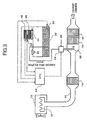
- FIG. 5 shows a configuration of a fourth embodiment of the exhaust emission purifying apparatus according to the present invention.
- the exhaust emission purifying apparatus in the present embodiment has a basic configuration common to that of the exhaust emission purifying apparatus in each of the first through third embodiments shown in Fig. 1 through Fig. 3 . Accordingly, the common constitutional elements are denoted by the same reference numerals, and therefore, the description thereof is omitted here.
- the NO x reduction catalyst 16 reductively purifying NO x is disposed. Further, on the upstream side of the NO x reduction catalyst 16, the injection nozzle 26 injecting to supply the reducing agent through an injection hole opened to the inside of the exhaust pipe 20, is disposed. Then, the compressed air stored in an air reservoir tank 60 passes through an electromagnetic switching valve 62 to be supplied to the reducing agent supply device 24.
- the urea water serving as the reducing agent which is stored in the storage tank 22, is supplied to the reducing agent supply device 24 via supply piping 64.
- the aqueous ammonia solution or a diesel oil mainly containing hydrocarbon may be used for the reducing agent, other than the urea water.
- a reducing agent temperature sensor 66 reducing agent temperature detecting device detecting a temperature of the urea water stored in the storage tank 22.
- the reducing agent supply device 24 which includes therein a pump, operates the pump to load the urea water on the compressed air supplied from the air reservoir tank 60, and makes the urea water to be in an atomized state, to supply it to the injection nozzle 26.
- a loading amount of the urea water is made variable by controlling an operation of the pump. Then, the excessive urea water, which was not supplied into the exhaust pipe 20 by the reducing agent supply device 24, is returned into the storage tank 22 via return piping 68.
- an electromagnetic switching valve 72 (blocking device) and a heat exchanging device 76 (heating device) which is provided with a heat exchanger pipe 74 heat exchanging with the urea water in the storage tank 22, are disposed in this order from the upstream.
- the electromagnetic switching valve 72 is operated to open and close, to open and block the cooling water circulating passage 70.
- the electromagnetic switching valve 72 when the electromagnetic switching valve 72 is opened, the cooling water which is heated by the engine 10 to operate as a heating medium is circulated within the cooling water circulating passage 70, so that the heat exchanging device 76 performs the heat exchange between the cooling water and the urea water via the heat exchanger pipe 74 to heat the urea water in the storage tank 22.
- a cooling water temperature sensor 78 heatating medium temperature detecting device
- an operating condition detecting sensor 80 detecting the engine operating conditions, such as the rotation speed, a load and the like, of the engine 10.
- a controller 82 incorporating therein a microcomputer receives the engine operating conditions from the operating condition detecting sensor 80, and controls to operate the pump in the reducing agent supply device 24 and the electromagnetic switching valve 62, so that the urea water of an optimum amount corresponding to the engine operating conditions is injected from the injection nozzle 26 to be supplied into the exhaust pipe 20. Further, the controller 82 receives the urea water temperature and the cooling water temperature respectively from the reducing agent temperature sensor 66 and the cooling water temperature sensor 78, and controls to operate the electromagnetic switching valve 72.
- the controller 82 is supplied with the power when a power supply switch such as a key switch is turned ON, to start the control.
- the control according to a flowchart in the figure is repetitively executed at every predetermined period of time.
- step 11 (to be referred to as S11 in the figure, and the same rule will be applied hereunder), the electromagnetic switching valve 72 is controlled to be closed.
- step 12 the temperature of the urea water in the storage tank 22 is input from the reducing agent temperature sensor 66.
- step 13 it is determined whether or not the urea water temperature input in step 12 is equal to or lower than the predetermined temperature Ta.
- the control routine proceeds to step 14 (YES).
- the control routine returns to step 11 (NO).
- the predetermined temperature Ta may be set to be slightly higher than the freezing temperature of the urea water.
- step 14 the temperature of the cooling water is input from the cooling water temperature sensor 78.
- step 15 it is determined whether or not the cooling water temperature input in step 14 is equal to or lower than the predetermined temperature Tb (first predetermined temperature).
- the control routine proceeds to step 16 (YES).
- the control routine returns to step 11 (NO).
- the predetermined temperature Tb may be set to be slightly lower than the lower limit temperature at which ammonia is generated from the urea water, and may be set to be slightly lower than 80°C, for example in the case of the urea water of 35 weighted percentage concentration.
- step 16 the electromagnetic switching valve 72 is controlled to be opened.
- step 17 the temperature of the urea water in the storage tank 22 is input from the reducing agent temperature sensor 66.
- step 18 it is determined whether or not the urea water temperature input in step 17 is equal to or higher than the predetermined temperature Tc (second predetermined temperature).
- the control routine proceeds to step 19 (YES).
- the control routine returns to step 14 (NO).
- the predetermined temperature Tc is set to be slightly higher than the predetermined temperature Ta, so that the temperature of the urea water in the storage tank 22 can be controlled to be between the predetermined temperature Ta and the predetermined temperature Tc.
- step 19 the electromagnetic switching valve 72 is controlled to be closed, and thereafter, the control routine proceeds to END.
- a series of controls in steps 11, 14 and 15 corresponds to first control means, and a series of controls in steps 17 through 19 corresponds to second control means.
- the exhaust emission from the engine 10 passes through the exhaust pipe 20 to be led into the NO x reduction catalyst 16.
- the controller 82 receives the engine operating conditions, such as the rotation speed, the load and the like, of the engine 10, from the operating condition detecting sensor 80, and controls operating of the pump in the reducing agent supply device 24 and the electromagnetic switching valve 62, so that the urea water of the optimum amount corresponding to the engine operating conditions is injected from the injection nozzle 26 to be supplied into the exhaust pipe 20.
- NO x in the exhaust emission is reductively removed with efficiency by the NO x reduction catalyst 16.
- the electromagnetic switching valve 72 is opened.
- the cooling water heated by the engine 10 is circulated within the cooling water circulating passage 70, the urea water in the storage tank 22 is subjected to the heat exchange with the cooling water via the heat exchanger pipe 74. Consequently, the freeze of the urea water can be prevented.
- the temperature of the urea water in the storage tank 22 is equal to or higher than the predetermined temperature Tc, namely, the temperature of the urea water in the storage tank 22 is high, since the electromagnetic switching valve 72 is closed, the urea water in the storage tank 22 is held at the temperature at which ammonia is not generated. As a result, it is further possible to suppress the generation of ammonia from the urea water in the storage tank 22.
- the controller 82 controls the electromagnetic switching valve 72 to be forcibly opened for a predetermined period of time. This control corresponds to third control means.
- the electromagnetic switching valve 72 it is desirable to enable the electromagnetic switching valve 72 to be manually opened. Thereby, when the cooling water is exchanged, it is possible to discharge the cooling water remaining in the cooling water circulating passage 70, to exchange all amount of the cooling water.
Landscapes
- Engineering & Computer Science (AREA)
- Chemical & Material Sciences (AREA)
- Chemical Kinetics & Catalysis (AREA)
- Combustion & Propulsion (AREA)
- General Engineering & Computer Science (AREA)
- Mechanical Engineering (AREA)
- Health & Medical Sciences (AREA)
- Toxicology (AREA)
- Materials Engineering (AREA)
- Biomedical Technology (AREA)
- Oil, Petroleum & Natural Gas (AREA)
- General Chemical & Material Sciences (AREA)
- Analytical Chemistry (AREA)
- Environmental & Geological Engineering (AREA)
- Exhaust Gas After Treatment (AREA)
- Exhaust Gas Treatment By Means Of Catalyst (AREA)
Claims (3)
- Appareil d'épuration des émissions d'échappement pour un moteur (10), comprenant :un catalyseur de réduction (16) disposé dans un système d'échappement de moteur (20) pour éliminer les oxydes d'azote par réduction au moyen d'un agent réducteur;un réservoir de stockage (22) qui stocke intérieurement l'agent réducteur;un dispositif d'acheminement d'agent réducteur (24) qui achemine l'agent réducteur stocké dans ledit réservoir de stockage (22) audit catalyseur de réduction (16);un dispositif de chauffage (74, 76) qui fait circuler un milieu chauffant chauffé par ledit moteur (10) dans ledit réservoir de stockage (22) pour chauffer ledit agent réducteur stocké dans ledit réservoir de stockage (22);un dispositif de fermeture (72) qui ferme un passage (70) qui amène ledit milieu chauffant audit réservoir de stockage (22);un dispositif de détection de la température du milieu chauffant (78) qui détecte la température dudit milieu chauffant; etdes premiers moyens de commande (82) destinés à commander ledit dispositif de fermeture (72) pour fermer ledit passage (70) lorsque la température du milieu chauffant détectée par ledit dispositif de détection de la température du milieu chauffant (78) est supérieure à une première température prédéterminée (Tb);un dispositif de détection de la température de l'agent réducteur (66) qui détecte la température de l'agent réducteur stocké dans ledit réservoir de stockage (22); etdes deuxièmes moyens de commande (82) destinés à commander ledit dispositif de fermeture (72) pour fermer ledit passage (70) lorsque la température de l'agent réducteur détectée par ledit dispositif de détection de la température de l'agent réducteur (66) est égale ou supérieure à une seconde de température prédéterminée (Tc).
- Appareil selon la revendication 1, comprenant en outre :des troisièmes moyens de commande (82) destinés à commander ledit dispositif de fermeture (72) pour annuler par force la fermeture dudit passage (70) pendant une période de temps prédéterminée immédiatement après qu'une opération dudit moteur (10) a été mise en action et aussi lorsque la température du milieu chauffant détectée par ledit dispositif de détection de la température du milieu chauffant (78) est supérieure à la température de congélation dudit agent réducteur.
- Appareil selon la revendication 1, dans lequel ledit dispositif de fermeture (72) peut être commandé manuellement pour annuler la fermeture dudit passage (70).
Applications Claiming Priority (4)
| Application Number | Priority Date | Filing Date | Title |
|---|---|---|---|
| JP2003327591A JP3687914B2 (ja) | 2003-09-19 | 2003-09-19 | エンジンの排気浄化装置 |
| JP2003339247A JP4166656B2 (ja) | 2003-09-30 | 2003-09-30 | エンジンの排気浄化装置 |
| JP2003339246A JP4166655B2 (ja) | 2003-09-30 | 2003-09-30 | エンジンの排気浄化装置 |
| EP04787623A EP1669567B1 (fr) | 2003-09-19 | 2004-09-02 | Dispositif de purification des gaz d'echappement d'un moteur |
Related Parent Applications (1)
| Application Number | Title | Priority Date | Filing Date |
|---|---|---|---|
| EP04787623.0 Division | 2004-09-02 |
Publications (2)
| Publication Number | Publication Date |
|---|---|
| EP2426328A1 EP2426328A1 (fr) | 2012-03-07 |
| EP2426328B1 true EP2426328B1 (fr) | 2013-04-10 |
Family
ID=34381777
Family Applications (3)
| Application Number | Title | Priority Date | Filing Date |
|---|---|---|---|
| EP11191519.5A Expired - Lifetime EP2426328B1 (fr) | 2003-09-19 | 2004-09-02 | Dispositif de purification de gaz d'échappement de moteur |
| EP04787623A Expired - Lifetime EP1669567B1 (fr) | 2003-09-19 | 2004-09-02 | Dispositif de purification des gaz d'echappement d'un moteur |
| EP11191521.1A Expired - Lifetime EP2426329B1 (fr) | 2003-09-19 | 2004-09-02 | Dispositif de purification de gaz d'échappement de moteur |
Family Applications After (2)
| Application Number | Title | Priority Date | Filing Date |
|---|---|---|---|
| EP04787623A Expired - Lifetime EP1669567B1 (fr) | 2003-09-19 | 2004-09-02 | Dispositif de purification des gaz d'echappement d'un moteur |
| EP11191521.1A Expired - Lifetime EP2426329B1 (fr) | 2003-09-19 | 2004-09-02 | Dispositif de purification de gaz d'échappement de moteur |
Country Status (3)
| Country | Link |
|---|---|
| US (1) | US7849674B2 (fr) |
| EP (3) | EP2426328B1 (fr) |
| WO (1) | WO2005028826A1 (fr) |
Families Citing this family (67)
| Publication number | Priority date | Publication date | Assignee | Title |
|---|---|---|---|---|
| JP2005105970A (ja) * | 2003-09-30 | 2005-04-21 | Nissan Diesel Motor Co Ltd | エンジンの排気浄化装置 |
| JP3686670B1 (ja) | 2004-10-29 | 2005-08-24 | 日産ディーゼル工業株式会社 | 排気浄化装置 |
| DE102006043098A1 (de) * | 2005-11-14 | 2007-06-28 | Robert Bosch Gmbh | Verfahren und Vorrichtung zur Temperaturführung in einer Abgasnachbehandlungsanlage |
| JP2007262900A (ja) * | 2006-03-27 | 2007-10-11 | Nissan Diesel Motor Co Ltd | 車両用液体タンク及びこれを備えたエンジンの排気浄化装置 |
| DE602007009676D1 (de) * | 2006-06-08 | 2010-11-18 | System zur lagerung von motorabgasadditiven | |
| FR2904855A1 (fr) * | 2006-08-08 | 2008-02-15 | Inergy Automotive Systems Res | Systeme de stockage et d'injection d'un additif dans des gaz d'echappement d'un moteur |
| EP1911508A3 (fr) * | 2006-10-13 | 2010-10-13 | Peugeot Citroën Automobiles SA | Système de traitement d'oxydes d'azote avec système de piégeage d'ammoniac |
| FR2907027B1 (fr) * | 2006-10-13 | 2009-05-15 | Peugeot Citroen Automobiles Sa | Systeme de traitement d'oxydes d'azote avec limitation des rejets d'ammoniac |
| FR2907026B1 (fr) * | 2006-10-13 | 2009-05-15 | Peugeot Citroen Automobiles Sa | Systeme de traitement d'oxydes d'azote avec systeme de piegeage d'ammoniac |
| JP4656039B2 (ja) | 2006-10-19 | 2011-03-23 | 株式会社デンソー | エンジンの排気浄化装置 |
| US7954311B2 (en) | 2007-03-15 | 2011-06-07 | Ford Global Technologies, Llc | Ammonia vapor management system and method |
| FR2916738B1 (fr) * | 2007-05-29 | 2009-09-18 | Plastic Omnium Cie | Reservoir pour vehicule automobile |
| FR2917791B1 (fr) * | 2007-06-20 | 2009-08-21 | Inergy Automotive Systems Res | Procede pour le demarrage d'une pompe. |
| JP2009013845A (ja) * | 2007-07-03 | 2009-01-22 | Hitachi Constr Mach Co Ltd | エンジン動力機械 |
| JP5028165B2 (ja) * | 2007-07-03 | 2012-09-19 | 日立建機株式会社 | エンジン動力機械 |
| US8146343B2 (en) | 2007-08-08 | 2012-04-03 | Ford Global Technologies, Llc | Approach for injecting a reductant |
| FR2920319A3 (fr) * | 2007-09-04 | 2009-03-06 | Renault Sas | Systeme de filtration de gaz toxiques emis par un reservoir additionnel de vehicule automobile. |
| JP4445001B2 (ja) * | 2007-11-21 | 2010-04-07 | 株式会社日本自動車部品総合研究所 | 排気浄化装置 |
| JP2009138526A (ja) * | 2007-12-03 | 2009-06-25 | Hitachi Constr Mach Co Ltd | 建設機械 |
| JP4325725B2 (ja) * | 2008-02-14 | 2009-09-02 | トヨタ自動車株式会社 | 内燃機関の尿素水供給装置 |
| US20090218409A1 (en) * | 2008-02-29 | 2009-09-03 | Wen-Lo Chen | Heating system for motor vehicle |
| ATE460973T1 (de) * | 2008-04-11 | 2010-04-15 | Umicore Ag & Co Kg | Abgasreinigungssystem zur behandlung von motorenabgasen mittels scr-katalysator |
| JP4666018B2 (ja) * | 2008-07-29 | 2011-04-06 | 株式会社デンソー | 内燃機関の排気浄化装置 |
| US8359831B2 (en) | 2008-10-31 | 2013-01-29 | Ti Group Automotive Systems, L.L.C. | Reactant delivery for engine exhaust gas treatment |
| DE102008043405B4 (de) * | 2008-11-03 | 2022-02-24 | Robert Bosch Gmbh | Verfahren zur Prüfung der Funktionsfähigkeit einer Pumpe |
| US8524185B2 (en) * | 2008-11-03 | 2013-09-03 | Basf Corporation | Integrated SCR and AMOx catalyst systems |
| US8459012B2 (en) * | 2008-11-19 | 2013-06-11 | Caterpillar Inc. | Method for purging a dosing system |
| US8122710B2 (en) * | 2008-12-01 | 2012-02-28 | International Engine Intellectual Property Company, Llc | Thermal management of urea dosing components in an engine exhaust after-treatment system |
| US20100170225A1 (en) * | 2009-01-08 | 2010-07-08 | Caterpillar Inc. | Exhaust treatment system having a reductant supply system |
| US8291926B2 (en) * | 2009-02-20 | 2012-10-23 | Caterpillar Inc. | Reductant dosing system having anti-aeration device |
| WO2010148237A2 (fr) * | 2009-06-18 | 2010-12-23 | Cummins Ip, Inc. | Appareil, système et procédé pour la régulation thermique d'une conduite de réducteur |
| JP2011052611A (ja) * | 2009-09-02 | 2011-03-17 | Toyota Industries Corp | 排気ガス浄化装置 |
| US8359833B2 (en) * | 2009-12-23 | 2013-01-29 | Caterpillar Inc. | Method for introducing a reductant into an exhaust stream |
| JP5573351B2 (ja) * | 2010-05-17 | 2014-08-20 | いすゞ自動車株式会社 | Scrシステム |
| US8438838B2 (en) * | 2010-10-11 | 2013-05-14 | Faurecia Emissions Control Technologies | Fuel-fired burner and heat exchanger system for heating a NOx reducing agent supply tank |
| WO2012054802A2 (fr) * | 2010-10-22 | 2012-04-26 | Ecomplete, Llc | Systèmes et procédés permettant une distribution de catalyseur extrêmement fiable à des moteurs à combustion interne |
| SE535474C2 (sv) * | 2010-12-02 | 2012-08-21 | Scania Cv Ab | Reduktionsmedelslagringssystem med uppvärmningsanordning |
| WO2012109126A1 (fr) * | 2011-02-08 | 2012-08-16 | Dow Global Technologies Llc | Système et procédé de réduction des émissions issues d'un procédé de combustion |
| DE102011012441A1 (de) | 2011-02-25 | 2012-08-30 | Emitec Gesellschaft Für Emissionstechnologie Mbh | Verfahren zum Heizen eines Fördersystems |
| WO2012155292A1 (fr) * | 2011-05-16 | 2012-11-22 | 苏州派格力减排系统有限公司 | Dispositif de stockage intégré pour agent réducteur scr |
| US20130026244A1 (en) * | 2011-07-28 | 2013-01-31 | Cnh America Llc | Work vehicle heating system and method |
| DE102011081628A1 (de) * | 2011-08-26 | 2013-02-28 | Robert Bosch Gmbh | Dosiersystem für ein flüssiges Reduktionsmittel |
| KR101305190B1 (ko) * | 2011-09-26 | 2013-09-12 | 기아자동차주식회사 | 요소수 히팅장치 및 그 방법 |
| US20130145749A1 (en) * | 2011-12-12 | 2013-06-13 | Caterpillar Inc. | Fluid manifold for use in an scr dosing system |
| WO2013174986A1 (fr) * | 2012-05-25 | 2013-11-28 | Emitec Gesellschaft Für Emissionstechnologie Mbh | Contenant comprenant un dispositif de chauffage pour un réservoir destiné au stockage d'un additif liquide |
| EP2886815B1 (fr) * | 2012-07-24 | 2017-03-15 | UD Trucks Corporation | Dispositif d'épuration de gaz d'échappement, et procédé pour dégeler un agent réducteur liquide ou un précurseur de celui-ci |
| PL2754870T3 (pl) * | 2013-01-11 | 2018-08-31 | Joseph Vögele AG | Układarka z układem zarządzania ciepłem |
| FR3003184B1 (fr) * | 2013-03-18 | 2016-12-09 | Inergy Automotive Systems Res (Societe Anonyme) | Systeme de depollution par reduction catalytique selective |
| EP3004697B1 (fr) | 2013-05-31 | 2019-05-15 | Dayco IP Holdings, LLC | Robinets-vannes à ressort pouvant être déplacés par un actionneur |
| US9574677B2 (en) | 2013-05-31 | 2017-02-21 | Dayco Ip Holdings, Llc | Solenoid-powered gate valve |
| CN104603509B (zh) | 2013-08-30 | 2017-03-08 | 戴科知识产权控股有限责任公司 | 能通过螺线管促动器运动的弹性闸门阀 |
| FR3010135B1 (fr) * | 2013-09-05 | 2018-03-02 | Peugeot Citroen Automobiles Sa | Systeme d'alimentation en agent reducteur d'une ligne d'echappement |
| JP5880514B2 (ja) * | 2013-10-02 | 2016-03-09 | 株式会社デンソー | エンジンの排気浄化システム |
| CN105723061B (zh) * | 2013-11-12 | 2018-05-18 | 戴科知识产权控股有限责任公司 | 具有由螺线管提供动力的闸阀的柴油发动机流体冷却系统 |
| US10221867B2 (en) | 2013-12-10 | 2019-03-05 | Dayco Ip Holdings, Llc | Flow control for aspirators producing vacuum using the venturi effect |
| US9666349B2 (en) | 2013-12-11 | 2017-05-30 | Dayco Ip Holdings, Llc | Magnetically actuated shut-off valve |
| DE102014001879A1 (de) * | 2014-02-14 | 2015-08-20 | Deutz Aktiengesellschaft | Brennkraftmaschine |
| CN104114826B (zh) * | 2014-02-26 | 2015-10-21 | 株式会社小松制作所 | 作业车辆 |
| JP6365099B2 (ja) | 2014-08-08 | 2018-08-01 | いすゞ自動車株式会社 | 尿素水の温度管理システム及び尿素水の温度管理方法 |
| JP6501794B2 (ja) * | 2014-12-25 | 2019-04-17 | ボルボトラックコーポレーション | エンジンの排気浄化装置 |
| EP3293376A4 (fr) * | 2015-05-07 | 2018-12-26 | Volvo Construction Equipment AB | Dispositifs de chauffage et de refroidissement de solution urée-eau pour équipement de construction |
| US9599246B2 (en) | 2015-08-05 | 2017-03-21 | Dayco Ip Holdings, Llc | Magnetically actuated shut-off valve |
| ITUB20155359A1 (it) * | 2015-11-06 | 2017-05-06 | Eltek Spa | Componente di serbatoio, in particolare per sistemi di trattamento di gas di scarico di motori a combustione interna |
| CN205243599U (zh) * | 2015-12-31 | 2016-05-18 | 天纳克(苏州)排放系统有限公司 | 尿素喷嘴 |
| JP6775169B2 (ja) * | 2017-02-09 | 2020-10-28 | エヌ・イーケムキャット株式会社 | 排ガス浄化装置 |
| CN108361099B (zh) * | 2018-05-16 | 2020-08-21 | 潍柴动力股份有限公司 | 一种汽车的电控风扇控制方法、控制装置和汽车 |
| US11624333B2 (en) | 2021-04-20 | 2023-04-11 | Kohler Co. | Exhaust safety system for an engine |
Family Cites Families (75)
| Publication number | Priority date | Publication date | Assignee | Title |
|---|---|---|---|---|
| US3556734A (en) * | 1968-02-05 | 1971-01-19 | Leander J Peterson | Exhaust gas conditioning apparatus |
| JPH0615815B2 (ja) | 1987-06-22 | 1994-03-02 | 三菱自動車工業株式会社 | ディ−ゼルパティキュレ−トトラップのバ−ナ−による再生装置 |
| JPH02173311A (ja) | 1988-12-23 | 1990-07-04 | Niles Parts Co Ltd | 払子コロナ発生装置及び排気ガス浄化装置 |
| KR950012137B1 (ko) * | 1989-02-02 | 1995-10-14 | 닛뽄 쇼크바이 카가꾸 고오교오 가부시기가이샤 | 디이젤엔진 배기가스 중의 질소산화물 제거방법 |
| JP2698993B2 (ja) | 1989-02-17 | 1998-01-19 | バブコツク日立株式会社 | 排ガス処理装置 |
| JPH02223625A (ja) | 1989-02-27 | 1990-09-06 | Shinko Electric Co Ltd | 脱硝装置におけるアンモニア水噴霧ノズルの閉塞防止装置 |
| JPH0621555B2 (ja) | 1989-02-27 | 1994-03-23 | 神鋼電機株式会社 | 脱硝装置におけるアンモニア混合装置 |
| JPH03129712A (ja) | 1989-10-14 | 1991-06-03 | Mitsubishi Electric Corp | トランスコイル |
| DE4009201A1 (de) * | 1990-01-25 | 1991-08-01 | Man Technologie Gmbh | Abgassystem mit einem partikelfilter und einem regenerierungsbrenner |
| JP2666508B2 (ja) | 1990-02-21 | 1997-10-22 | トヨタ自動車株式会社 | 内燃機関の排気浄化装置 |
| JPH04237860A (ja) | 1991-01-21 | 1992-08-26 | Toyota Motor Corp | 蒸発燃料処理装置 |
| JPH04292565A (ja) | 1991-03-20 | 1992-10-16 | Nissan Motor Co Ltd | 燃料蒸発ガス処理装置 |
| US5176325A (en) * | 1991-05-14 | 1993-01-05 | Spraying Systems Co. | Air atomizing spray nozzle assembly |
| JPH05171921A (ja) | 1991-12-20 | 1993-07-09 | Mazda Motor Corp | 排気ガス浄化装置 |
| JPH05222923A (ja) * | 1992-02-06 | 1993-08-31 | Hino Motors Ltd | エンジン排ガスの触媒によるNOx低減装置 |
| CA2088713C (fr) | 1992-02-24 | 1999-11-16 | Hans Thomas Hug | Nettoyage des gaz d'echappement des installations de combustion |
| JP2847594B2 (ja) | 1992-02-24 | 1999-01-20 | 日野自動車工業株式会社 | 排ガス浄化装置 |
| DE59202165D1 (de) * | 1992-05-08 | 1995-06-14 | Siemens Ag | Einrichtung zur Entstickung von Abgas eines Verbrennungsmotors. |
| US5372312A (en) * | 1993-08-23 | 1994-12-13 | Spraying Systems Co. | Air atomizing spray nozzle assembly with angled discharge orifices |
| JP2951831B2 (ja) | 1993-11-05 | 1999-09-20 | 三菱電機株式会社 | 内燃機関の排気ガス浄化装置 |
| JP2937738B2 (ja) | 1994-04-05 | 1999-08-23 | 株式会社新潟鉄工所 | 排煙脱硝装置の還元剤噴霧装置 |
| FI98403C (fi) * | 1994-07-01 | 1997-06-10 | Waertsilae Diesel Int | Menetelmä äänenvaimenninyksikön käyttämiseksi ja järjestelmä menetelmän soveltamiseksi isossa dieselmoottorissa |
| WO1996008639A1 (fr) | 1994-09-13 | 1996-03-21 | Siemens Aktiengesellschaft | Procede et systeme permettant d'introduire un fluide dans une dispositif d'epuration de gaz d'echappement |
| DE4436397B4 (de) * | 1994-10-12 | 2006-06-08 | Robert Bosch Gmbh | Einrichtung zum Nachbehandeln von Abgasen |
| DE4441261A1 (de) | 1994-11-19 | 1996-05-23 | Bosch Gmbh Robert | Einrichtung zum Nachbehandeln von Abgasen einer Brennkraftmaschine |
| US5921472A (en) * | 1994-12-13 | 1999-07-13 | Spraying Systems Co. | Enhanced efficiency nozzle for use in fluidized catalytic cracking |
| US5603453A (en) | 1994-12-30 | 1997-02-18 | Lab S.A. | Dual fluid spray nozzle |
| US5553783A (en) * | 1995-01-09 | 1996-09-10 | Bete Fog Nozzle, Inc. | Flat fan spray nozzle |
| DE19531028A1 (de) * | 1995-08-23 | 1997-02-27 | Siemens Ag | Verfahren zur Abgasreinigung und Abgas-Reinigungseinrichtung für einen Verbrennungsmotor |
| US5992141A (en) * | 1996-04-02 | 1999-11-30 | Kleen Air Systems, Inc. | Ammonia injection in NOx control |
| JPH10121949A (ja) | 1996-10-24 | 1998-05-12 | Fuji Heavy Ind Ltd | エンジンの排気ガス浄化装置 |
| DE19726392A1 (de) | 1997-06-21 | 1998-12-24 | Bosch Gmbh Robert | Gemischabgabevorrichtung |
| DE19728343C5 (de) * | 1997-07-03 | 2013-02-21 | Robert Bosch Gmbh | Verfahren und Vorrichtung zur selektiven katalytischen NOx-Reduktion |
| DE19738859A1 (de) * | 1997-09-05 | 1999-03-11 | Bosch Gmbh Robert | Gemischabgabevorrichtung |
| WO1999030811A1 (fr) | 1997-12-12 | 1999-06-24 | Fev Motorentechnik Gmbh & Co. Kommanditgesellschaft | Procede de reduction d'oxyde d'azote contenus dans des gaz d'evacuation contenant de l'oxygene, en particulier dans des gaz d'echappement de moteurs a combustion interne |
| JP3277881B2 (ja) | 1998-04-06 | 2002-04-22 | トヨタ自動車株式会社 | 内燃機関の排気浄化装置 |
| DE19818448A1 (de) | 1998-04-24 | 1999-10-28 | Siemens Ag | Verfahren und Vorrichtung zur katalytischen Reduzierung von Stickoxiden im Abgas einer Verbrennungsanlage |
| ATE246535T1 (de) * | 1998-05-11 | 2003-08-15 | Siemens Ag | Verfahren und vorrichtung zur selektiven katalytischen reduktion von stickoxiden in einem sauerstoffhaltigen gasförmigen medium |
| JP3565035B2 (ja) * | 1998-07-10 | 2004-09-15 | 三菱ふそうトラック・バス株式会社 | 燃焼排ガス用NOx還元システム |
| JP2000027627A (ja) | 1998-07-13 | 2000-01-25 | Hino Motors Ltd | 排気ガス浄化触媒用還元剤保温装置及びそれを組込んだ排気ガス浄化装置 |
| US6279603B1 (en) * | 1998-10-01 | 2001-08-28 | Ambac International | Fluid-cooled injector |
| DE19855338A1 (de) * | 1998-12-01 | 2000-06-08 | Bosch Gmbh Robert | Vorrichtung zum Einbringen eines Reduktionsmittels in einen Abgasrohrabschnitt einer Brennkraftmaschine |
| JP2000257419A (ja) | 1999-03-03 | 2000-09-19 | Toyota Motor Corp | 排気浄化方法及び装置 |
| DE19919426C1 (de) * | 1999-04-28 | 2000-03-30 | Siemens Ag | Ventilaufnahmevorrichtung für ein Dosierventil einer Abgasnachbehandlungsanlage |
| JP2000314308A (ja) | 1999-04-30 | 2000-11-14 | Isuzu Motors Ltd | ディーゼルエンジンの排気ガス浄化装置 |
| JP2001020724A (ja) | 1999-07-07 | 2001-01-23 | Isuzu Motors Ltd | ディーゼルエンジンのNOx浄化装置 |
| JP2001027112A (ja) | 1999-07-13 | 2001-01-30 | Meidensha Corp | 脱硝装置 |
| DE19935920C2 (de) * | 1999-07-30 | 2003-04-17 | Siemens Ag | Vorrichtung und Verfahren zum Beheizen eines Reduktionsmittelvorratsbehälters einer Abgasnachbehandlungsanlage für eine Brennkraftmaschine |
| JP4352516B2 (ja) | 1999-08-03 | 2009-10-28 | トヨタ自動車株式会社 | 内燃機関の排気浄化装置 |
| DE19940298A1 (de) * | 1999-08-25 | 2001-03-01 | Bosch Gmbh Robert | Verfahren und Vorrichtung zur Bestimmung eines Reduktionsmittels und/oder der Reduktionsmittelkonzentration einer Reduktionsmittellösung in einem Katalysatorsystem zugeordneten Reduktionsmitteltank |
| DE19946901A1 (de) | 1999-09-30 | 2001-04-05 | Bosch Gmbh Robert | Vorrichtung zur Beaufschlagung eines strömenden Gases mit einem Reaktionsmittel |
| DE19956493C1 (de) | 1999-11-24 | 2001-01-04 | Siemens Ag | Vorrichtung und Verfahren zum Entsticken von Abgas einer Brennkraftmaschine |
| JP2001173431A (ja) | 1999-12-17 | 2001-06-26 | Isuzu Motors Ltd | 排気浄化システム |
| US6167698B1 (en) * | 1999-12-21 | 2001-01-02 | Ford Motor Company | Exhaust gas purification system for a lean burn engine |
| JP3600509B2 (ja) | 2000-06-23 | 2004-12-15 | トヨタ自動車株式会社 | 内燃機関の排気浄化装置 |
| JP3487267B2 (ja) | 2000-07-17 | 2004-01-13 | トヨタ自動車株式会社 | 内燃機関の排気浄化装置 |
| DE10047516A1 (de) * | 2000-09-22 | 2002-04-18 | Bosch Gmbh Robert | Verfahren und Vorrichtung zur Dosierung eines Reduktionsmittels zur Entfernung von Stickoxiden aus Abgasen |
| JP3545691B2 (ja) | 2000-09-27 | 2004-07-21 | 日野自動車株式会社 | 排気浄化装置の運転方法 |
| US6725651B2 (en) * | 2000-11-16 | 2004-04-27 | Toyota Jidosha Kabushiki Kaisha | Reducing agent for emission control system, reducing-agent supply device, and emission control system using the reducing agent |
| JP3600522B2 (ja) * | 2000-11-20 | 2004-12-15 | トヨタ自動車株式会社 | 内燃機関の還元剤供給装置 |
| DE10060808B4 (de) | 2000-12-07 | 2004-12-02 | Robert Bosch Gmbh | Abgasreinigungsanlage |
| JP3794468B2 (ja) | 2000-12-19 | 2006-07-05 | 三菱電機株式会社 | 内燃機関の排気ガス浄化装置 |
| JP4917208B2 (ja) | 2001-01-22 | 2012-04-18 | 川崎重工業株式会社 | 脱硝装置用液体還元剤の供給方法及び装置 |
| JP4131783B2 (ja) | 2001-05-09 | 2008-08-13 | 日産ディーゼル工業株式会社 | 内燃機関の排気浄化装置 |
| JP2003010644A (ja) | 2001-07-03 | 2003-01-14 | Meidensha Corp | 脱硝装置の尿素水気化器 |
| DE10155675A1 (de) * | 2001-08-18 | 2003-05-28 | Bosch Gmbh Robert | Verfahren und Vorrichtung zur Speicherung und Dosierung eines Reduktionsmittels |
| EP1420873B1 (fr) | 2001-08-18 | 2008-03-26 | Robert Bosch Gmbh | Ensemble et procede de stockage et de dosage d'un agent de reduction |
| JP4132858B2 (ja) | 2002-02-13 | 2008-08-13 | 株式会社小松製作所 | 排気ガス浄化装置 |
| DE10206028A1 (de) * | 2002-02-14 | 2003-08-28 | Man Nutzfahrzeuge Ag | Verfahren und Vorrichtung zur Erzeugung von Ammoniak |
| JP2003260332A (ja) | 2002-03-13 | 2003-09-16 | Mitsui & Co Ltd | 排煙脱硝用の還元剤組成物の簡易型供給装置 |
| US6814303B2 (en) * | 2002-04-03 | 2004-11-09 | Cleaire Advanced Emission Controls | Fluid-cooled mount for an injector |
| JP2004004405A (ja) | 2002-04-19 | 2004-01-08 | Bridgestone Corp | 画像表示装置 |
| AU2003273138A1 (en) * | 2002-05-07 | 2003-12-12 | Extengine Transport Systems | Emission control system |
| JP2003328734A (ja) | 2002-05-09 | 2003-11-19 | Babcock Hitachi Kk | 尿素の付着を防止した排気管および排ガス脱硝装置 |
| JP4301773B2 (ja) | 2002-07-09 | 2009-07-22 | 三菱重工業株式会社 | 還元剤供給装置 |
-
2004
- 2004-09-02 EP EP11191519.5A patent/EP2426328B1/fr not_active Expired - Lifetime
- 2004-09-02 EP EP04787623A patent/EP1669567B1/fr not_active Expired - Lifetime
- 2004-09-02 EP EP11191521.1A patent/EP2426329B1/fr not_active Expired - Lifetime
- 2004-09-02 US US10/572,558 patent/US7849674B2/en active Active
- 2004-09-02 WO PCT/JP2004/012743 patent/WO2005028826A1/fr active Application Filing
Also Published As
| Publication number | Publication date |
|---|---|
| EP2426329A1 (fr) | 2012-03-07 |
| WO2005028826A1 (fr) | 2005-03-31 |
| EP2426329B1 (fr) | 2013-05-01 |
| EP2426328A1 (fr) | 2012-03-07 |
| EP1669567A4 (fr) | 2010-05-26 |
| EP1669567A1 (fr) | 2006-06-14 |
| US7849674B2 (en) | 2010-12-14 |
| EP1669567B1 (fr) | 2012-03-21 |
| US20070180816A1 (en) | 2007-08-09 |
Similar Documents
| Publication | Publication Date | Title |
|---|---|---|
| EP2426328B1 (fr) | Dispositif de purification de gaz d'échappement de moteur | |
| US5884475A (en) | Method and device for introducing liquid into an exhaust-gas purification system | |
| US7712304B2 (en) | Method for after treatment of exhaust gases, and exhaust gas after treatment array | |
| JP4873580B2 (ja) | NOxを選択的に触媒により還元する方法および装置 | |
| US8424777B2 (en) | Reducing agent heating system | |
| US8011176B2 (en) | Exhaust emission purifying apparatus for internal combustion engine | |
| CN101821485B (zh) | 还原剂供给系统的控制装置及控制方法 | |
| EP1836379B1 (fr) | Systeme de stockage et d'injection d'un additif dans des gaz d'echappement d'un moteur | |
| EP1925804B1 (fr) | Purificateur de gaz d'échappement pour moteur | |
| EP1741887B1 (fr) | Dispositif d'injection de liquide pour dispositif de post-traitement de gaz d'échappement | |
| JP2008223763A (ja) | アンモニア蒸気管理方法 | |
| US20100095653A1 (en) | System and method for heating a reducing agent associated with a reducing agent distribution system | |
| JP2005256727A (ja) | エンジンの排気浄化装置 | |
| JP3687914B2 (ja) | エンジンの排気浄化装置 | |
| WO2006054632A1 (fr) | Appareil de purification des gaz d’echappement | |
| CN113646515A (zh) | 发动机系统 | |
| JP4087350B2 (ja) | エンジンの排気浄化装置 | |
| CN112576346B (zh) | 气驱尿素泵系统的排气控制方法 | |
| JP4261393B2 (ja) | 排気浄化装置の制御方法 | |
| JP2006105014A (ja) | 還元剤利用式排ガス浄化装置 | |
| JP4166655B2 (ja) | エンジンの排気浄化装置 | |
| JP4166656B2 (ja) | エンジンの排気浄化装置 | |
| JP3759667B2 (ja) | 排ガス浄化触媒用の還元剤添加装置 | |
| JP4693668B2 (ja) | 排気浄化装置 | |
| JPH0777032A (ja) | ディーゼルエンジン用排気浄化装置 |
Legal Events
| Date | Code | Title | Description |
|---|---|---|---|
| AC | Divisional application: reference to earlier application |
Ref document number: 1669567 Country of ref document: EP Kind code of ref document: P |
|
| AK | Designated contracting states |
Kind code of ref document: A1 Designated state(s): DE IT NL SE |
|
| PUAI | Public reference made under article 153(3) epc to a published international application that has entered the european phase |
Free format text: ORIGINAL CODE: 0009012 |
|
| 17P | Request for examination filed |
Effective date: 20120825 |
|
| RIC1 | Information provided on ipc code assigned before grant |
Ipc: F01N 3/08 20060101AFI20121030BHEP Ipc: F01N 3/20 20060101ALI20121030BHEP Ipc: F01N 3/24 20060101ALI20121030BHEP |
|
| GRAP | Despatch of communication of intention to grant a patent |
Free format text: ORIGINAL CODE: EPIDOSNIGR1 |
|
| GRAS | Grant fee paid |
Free format text: ORIGINAL CODE: EPIDOSNIGR3 |
|
| GRAA | (expected) grant |
Free format text: ORIGINAL CODE: 0009210 |
|
| AC | Divisional application: reference to earlier application |
Ref document number: 1669567 Country of ref document: EP Kind code of ref document: P |
|
| AK | Designated contracting states |
Kind code of ref document: B1 Designated state(s): DE IT NL SE |
|
| REG | Reference to a national code |
Ref country code: SE Ref legal event code: TRGR |
|
| REG | Reference to a national code |
Ref country code: DE Ref legal event code: R096 Ref document number: 602004041746 Country of ref document: DE Effective date: 20130606 |
|
| REG | Reference to a national code |
Ref country code: NL Ref legal event code: T3 |
|
| PLBE | No opposition filed within time limit |
Free format text: ORIGINAL CODE: 0009261 |
|
| STAA | Information on the status of an ep patent application or granted ep patent |
Free format text: STATUS: NO OPPOSITION FILED WITHIN TIME LIMIT |
|
| 26N | No opposition filed |
Effective date: 20140113 |
|
| REG | Reference to a national code |
Ref country code: DE Ref legal event code: R097 Ref document number: 602004041746 Country of ref document: DE Effective date: 20140113 |
|
| REG | Reference to a national code |
Ref country code: DE Ref legal event code: R081 Ref document number: 602004041746 Country of ref document: DE Owner name: VOLVO TRUCK CORPORATION, SE Free format text: FORMER OWNER: NISSAN DIESEL MOTOR CO., LTD., AGEO-SHI, SAITAMA-KEN, JP |
|
| REG | Reference to a national code |
Ref country code: NL Ref legal event code: PD Owner name: VOLVO TRUCK CORPORATION; SE Free format text: DETAILS ASSIGNMENT: CHANGE OF OWNER(S), ASSIGNMENT; FORMER OWNER NAME: VOLVO GROUP SWEDEN AB Effective date: 20211125 |
|
| PGFP | Annual fee paid to national office [announced via postgrant information from national office to epo] |
Ref country code: SE Payment date: 20220923 Year of fee payment: 19 Ref country code: NL Payment date: 20220926 Year of fee payment: 19 Ref country code: DE Payment date: 20220527 Year of fee payment: 19 |
|
| PGFP | Annual fee paid to national office [announced via postgrant information from national office to epo] |
Ref country code: IT Payment date: 20220926 Year of fee payment: 19 |
|
| REG | Reference to a national code |
Ref country code: DE Ref legal event code: R119 Ref document number: 602004041746 Country of ref document: DE |
|
| REG | Reference to a national code |
Ref country code: SE Ref legal event code: EUG |
|
| REG | Reference to a national code |
Ref country code: NL Ref legal event code: MM Effective date: 20231001 |
|
| PG25 | Lapsed in a contracting state [announced via postgrant information from national office to epo] |
Ref country code: NL Free format text: LAPSE BECAUSE OF NON-PAYMENT OF DUE FEES Effective date: 20231001 |
|
| PG25 | Lapsed in a contracting state [announced via postgrant information from national office to epo] |
Ref country code: NL Free format text: LAPSE BECAUSE OF NON-PAYMENT OF DUE FEES Effective date: 20231001 |
|
| PG25 | Lapsed in a contracting state [announced via postgrant information from national office to epo] |
Ref country code: DE Free format text: LAPSE BECAUSE OF NON-PAYMENT OF DUE FEES Effective date: 20240403 |
|
| PG25 | Lapsed in a contracting state [announced via postgrant information from national office to epo] |
Ref country code: SE Free format text: LAPSE BECAUSE OF NON-PAYMENT OF DUE FEES Effective date: 20230903 |