EP2421128A1 - Stator und herstellungsverfahren dafür - Google Patents
Stator und herstellungsverfahren dafür Download PDFInfo
- Publication number
- EP2421128A1 EP2421128A1 EP09843300A EP09843300A EP2421128A1 EP 2421128 A1 EP2421128 A1 EP 2421128A1 EP 09843300 A EP09843300 A EP 09843300A EP 09843300 A EP09843300 A EP 09843300A EP 2421128 A1 EP2421128 A1 EP 2421128A1
- Authority
- EP
- European Patent Office
- Prior art keywords
- stator
- stator core
- flange portion
- fixing hole
- fixing
- Prior art date
- Legal status (The legal status is an assumption and is not a legal conclusion. Google has not performed a legal analysis and makes no representation as to the accuracy of the status listed.)
- Withdrawn
Links
Images


Classifications
-
- H—ELECTRICITY
- H02—GENERATION; CONVERSION OR DISTRIBUTION OF ELECTRIC POWER
- H02K—DYNAMO-ELECTRIC MACHINES
- H02K15/00—Methods or apparatus specially adapted for manufacturing, assembling, maintaining or repairing of dynamo-electric machines
- H02K15/14—Casings; Enclosures; Supports
-
- H—ELECTRICITY
- H02—GENERATION; CONVERSION OR DISTRIBUTION OF ELECTRIC POWER
- H02K—DYNAMO-ELECTRIC MACHINES
- H02K5/00—Casings; Enclosures; Supports
- H02K5/26—Means for adjusting casings relative to their supports
-
- Y—GENERAL TAGGING OF NEW TECHNOLOGICAL DEVELOPMENTS; GENERAL TAGGING OF CROSS-SECTIONAL TECHNOLOGIES SPANNING OVER SEVERAL SECTIONS OF THE IPC; TECHNICAL SUBJECTS COVERED BY FORMER USPC CROSS-REFERENCE ART COLLECTIONS [XRACs] AND DIGESTS
- Y10—TECHNICAL SUBJECTS COVERED BY FORMER USPC
- Y10T—TECHNICAL SUBJECTS COVERED BY FORMER US CLASSIFICATION
- Y10T29/00—Metal working
- Y10T29/49—Method of mechanical manufacture
- Y10T29/49002—Electrical device making
- Y10T29/49009—Dynamoelectric machine
-
- Y—GENERAL TAGGING OF NEW TECHNOLOGICAL DEVELOPMENTS; GENERAL TAGGING OF CROSS-SECTIONAL TECHNOLOGIES SPANNING OVER SEVERAL SECTIONS OF THE IPC; TECHNICAL SUBJECTS COVERED BY FORMER USPC CROSS-REFERENCE ART COLLECTIONS [XRACs] AND DIGESTS
- Y10—TECHNICAL SUBJECTS COVERED BY FORMER USPC
- Y10T—TECHNICAL SUBJECTS COVERED BY FORMER US CLASSIFICATION
- Y10T29/00—Metal working
- Y10T29/53—Means to assemble or disassemble
- Y10T29/5313—Means to assemble electrical device
- Y10T29/53143—Motor or generator
Definitions
- the present invention relates to a stator and a method for manufacturing the same.
- a motor and a generator for serving as a rotating electric machine installed on a vehicle such as an automobile have a rotor and a stator which is in an annular form and arranged annularly around the rotor.
- a stator which is in an annular form and arranged annularly around the rotor.
- energizing the stator provides rotation force
- rotation of the rotor provides electric current.
- the stator has an annular stator core having a stator winding.
- the stator core is resin-sealed and the resin-sealed stator core is accommodated in a stator case which is referred to as a cooling jacket.
- Japanese Patent Laying-Open No. 2006-254562 (PTL 1) listed below discloses a rotating electric machine having a structure in which a stator core is provided with a convex portion, a motor case (corresponding to a stator case) is provided with a concave portion, and the convex portion of the stator core is fitted into the concave portion of the motor case in a manner interposing a mold resin therebetween.
- the mold resin interposed between the convex portion and the concave portion fixes the convex portion of the stator core in the concave portion, thereby restricting the movement of the stator core relative to the motor case.
- Japanese Patent Laying-Open No. 2006-174637 listed below discloses a method for manufacturing a stator of a rotating electric machine.
- the method adopts a stator manufacturing method in which a stator core is resin-molded, and according to the disclosed method, a mold resin is injected into a stator case with a convex portion provided on the stator core fitted in a concave portion provided in the inner surface of the stator case.
- the convex portion of the stator core fitted in the concave portion of the stator case restricts the stator core from being moved by resin-molding pressure in injecting the resin.
- PTLs 1 and 2 above disclose a technique for restricting a stator core from moving relative to a stator case.
- the documents disclose nothing about a problem that a positioning hole provided in the stator case experiences a deviation which occurs in a stator manufacturing process.
- a stator case is provided with a positioning hole for fixing a rotating electric machine to an external housing.
- This positioning hole is provided in a flange portion extending outwardly from the stator case.
- the positioning hole is provided in a flange portion provided on a fastening ring for a stator core and constituting the stator case.
- the fastening ring is fixed relative to the stator core by "shrinkage fitting". More specifically, the fastening ring is first heated to expand the fastening ring, thereby to enlarge the inner diameter of the fastening ring. Inside the fastening ring having the enlarged inner diameter, the stator core is accommodated. Subsequently, the fastening ring is cooled, causing the fastening ring to have a contracted inner diameter. As a result, the fastening ring is fixed onto the outer circumferential surface of the stator core.
- a fastening ring provided with a positioning hole is thus enlarged by heating and contracted by cooling in a manufacturing process of a stator, a deviation from an originally designed position may occur in the position of the positioning hole.
- Such enlargement and contraction of the fastening ring can also occur in molding using a mold resin.
- a positional deviation of a stator causes degradation of the performance of a rotating electric machine.
- the present invention has been made to solve the problems above, and an object of the invention is to provide a stator with a structure which does not cause degradation of the performance of a rotating electric machine and a method for manufacturing the stator.
- a method for manufacturing a stator having an annular form and for use in a rotating electric machine includes the steps of positioning and fixing a stator core on a jig such that a central position of the stator core agrees with a rotational axis of a rotating electric machine and forming a fixing hole in a flange portion provided on a fastening ring for the stator core, using the central position as a reference for positioning, with the stator core fixed by the jig.
- the step of positioning and fixing the stator core on a jig includes the steps of positioning and fixing a stator core on a centering jig such that the central position of the stator core agrees with the rotational axis of a rotating electric machine and fixing the fastening ring onto an outer circumferential surface of the stator core, with the stator core fixed by the centering jig.
- the step of forming the fixing hole in the flange portion includes the step of performing drilling on the flange portion with a drill, using the center position as a reference for positioning.
- the step of forming the fixing hole in the flange portion includes the step of fixing a hollow rivet to a pilot hole provided in the flange portion, using the center position as a reference for positioning.
- the step of forming the fixing hole in the flange portion includes the step of performing punching on the flange portion by press punching, using the center position as a reference for positioning
- the step of positioning and fixing the stator core on a jig includes the step of fixing the stator core having an outer circumferential surface fastened by the fastening ring, within a mold for resin-molding.
- the step of performing resin-molding the fixing hole on a pilot hole provided in the flange portion is performed in and simultaneously with the step of resin-molding the stator core fixed within the mold.
- the stator based on the present invention is a stator having an annular form and for use in a rotating electric machine, and the stator includes a stator core and a fastening ring fixed onto an outer circumferential surface of the stator core.
- the fastening ring is provided with a flange portion having a fixing hole formed relative to a central position of the stator core serving as a rotational axis of a rotating electric machine.
- the fixing hole is a hole formed by performing drilling on the flange portion.
- the fixing hole is a hole formed by fixation of a hollow rivet to a pilot hole provided in the flange portion.
- the fixing hole is a hole formed by performing press punching on the flange portion.
- the fixing hole is a hole formed by performing resin-molding on a pilot hole provided in the flange portion.
- stator with a structure which does not degrade the performance of a rotating electric machine and a method for manufacturing the stator can be provided.
- a stator 1 has an annular stator core 501 having a stator winding.
- Stator core 501 is resin-sealed and the resin-sealed stator core 501 is accommodated in a case which is referred to as a cooling jacket.
- the cooling jacket is configured of a fastening ring 100 located outside stator core 501, an inner ring 200 located outside stator core 501, and coil end covers 300, 400 located on coil ends at the either end of stator core 501.
- stator core 501 has the outer circumferential surface onto which fastening ring 100 is fixed.
- Fastening ring 100 has three points on the circumference of the ring at intervals of 120 degrees, each provided with a flange portion 110 extending outwardly in the radial direction.
- Each flange portion 110 is provided with a fixing hole 110h.
- Fixing hole 110h provided in flange portion 110 is provided at an accurate position relative to a central position A1 of stator core 501 serving as a rotational axis of a rotating electric machine.
- a method for manufacturing a stator including the step of opening fixing hole 110h will be described below. It is noted that sectional views shown in the following Figs. 3 to 5 correspond to sections taken along a line IV-IV and seen in the direction of arrows in Fig. 2 .
- stator core 501 is positioned and fixed on a centering jig 700 such that central position A1 of stator core 501 agrees with the rotational axis of a rotating electric machine.
- Centering jig 700 is provided with an annular concave region 701 for receiving a lower end of stator core 501 and includes an inner diameter retaining member 702 pressing on stator core 501 outwardly in the radial direction from the inner circumferential surface side of stator core 501.
- Stator core 501 pressed on outwardly by inner diameter retaining member 702 completes positioning of stator core 501.
- fastening ring 100 is heated by a heater 600 and keeps its inner diameter in an enlarged state. Inside fastening ring 100 with the enlarged inner diameter, stator core 501 is accommodated. Subsequently, fastening ring 100 is cooled, causing fastening ring 100 to have a contracted diameter. As a result, fastening ring 100 is fixed onto the outer circumferential surface of stator core 501.
- fixing hole 110h is formed by drilling with a drill DI in flange portion 110 provided on fastening ring 100 for stator core 501, using central position A1 as a reference for positioning. As shown in Figs. 6 and 7 , fixing hole 110h is opened to be located at a distance R1 relative to central position A1. In a plan view, the fixing hole 110h is opened at a predetermined central angle interval (for example, intervals of 120°) relative to central position A1.
- the stator and the method for manufacturing the stator in the first embodiment includes the steps of positioning and fixing stator core 501 on centering jig 700 such that central position A1 of stator core 501 agrees with the rotational axis of a rotating electric machine and forming fixing hole 110h in flange portion 110 provided on fastening ring 100 for stator core 501, using central position A1 as a reference for positioning, with stator core 501 fixed by centering jig 700. 34 Employment of these steps allows fixing hole 110h to be formed at an accurate position relative to central position A1 without being affected by occurrence of deviation caused by heating and cooling fastening ring 100.
- the stator in the present embodiment is characterized by having a hole which serves as a fixing hole 110h provided in flange portion 110 provided on fastening ring 100 and which is formed by fixation of a hollow rivet 810 to a pilot hole 110m prepared in flange portion 110.
- the step of forming fixing hole 110h will be described below. It is noted that steps until fixing fastening ring 100 to a stator core 501 are same as those in the first embodiment described above.
- a positioning pin 800 is provided in advance at an accurate position relative to central position A1.
- Hollow rivet 810 is mounted on positioning pin 800.
- fastening ring 100 is fixed onto stator core 501. Since flange portion 110 of fastening ring 100 is in advance provided with pilot hole 110m, positioning pin 800 and hollow rivet 810 do not interfere with flange portion 110.
- stator and the method for manufacturing the same in the present embodiment also provide the same function and effects as those in the first embodiment above.
- the stator in the present embodiment is characterized by having a hole which serves as a fixing hole 110h provided in flange portion 110 provided on fastening ring 100 and which is formed by performing press punching on flange portion 110.
- the step of forming fixing hole 110h will be described below. It is noted that steps until fixing fastening ring 100 to a stator core 501 are same as those in the first embodiment described above.
- a clearance hole 703 is provided in advance at an accurate position relative to central position A1.
- flange portion 110 placed on centering jig 700, flange portion 110 is punched through by a punch P1. This results in formation of a punching burr portion 110p in an approximately cylindrical shape as well as formation of fixing hole 110h defined by punching burr portion 110p, as shown in Figs. 12 and 13 .
- Clearance hole 703 and punch PI are provided to be located at distance R11 relative to central position A1. Accordingly, fixing hole 110h is opened to be located at distance R1 relative to central portion A1. In a plan view, fixing hole 110h is opened at a predetermined central angle interval (for example, intervals of 120°) relative to central position A1.
- stator and the method for manufacturing the same in the present embodiment also provide the same function and effects as those in the first embodiment described above.
- the step of fixing fastening ring 100 onto stator core is finished before formation of fixing hole 110h, which allows fixing hole 110h to be formed at an accurate position relative to central position A1 without being affected by occurrence of deviation caused by heating and cooling of fastening ring 100.
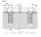
- fixing hole 110h After formation of fixing hole 110h, however, it is necessary to perform the step of resin-molding the stator core. At this time, in injecting a mold resin, fastening ring 100 is heated and cooled again, and consequently, a positional deviation of fixing hole 110h may occur. In such a case, a hole formed by performing resin-molding on pilot hole 110m may be used as fixing hole 110h, as shown below.
- stator core 501 having the outer circumferential surface to which fastening ring 100 is fastened is placed within cavities 1000C, 2000C formed by a lower mold 1000 and an upper mold 2000 for resin-molding.
- Lower mold 1000 and upper mold 2000 have portions circumferentially outward to fastening ring 100 which are provided with a resin introducing concave portion 1000h and a hole forming pin 2000p, respectively.
- Resin introducing concave portion 1000h is located below pilot hole 110m provided in flange portion 110, and hole forming pin 2000p is provided to pass through pilot hole 110m and abut on the base of resin introducing concave portion 1000h. Further, hole forming pin 2000p is provided at an accurate position relative to central portion A1.
- Hole forming pin 2000p is provided to be located at distance R1 relative to central position A1. Accordingly, fixing hole 110h is opened to be located at distance R1 relative to central portion A1. In a plan view, fixing hole 110h is opened at a predetermined central angle interval (for example, intervals of 120°) relative to central position A1.
- fixing hole 110h is concurrently formed with the step of resin-molding the stator core, fixing hole 110h can be formed at an accurate position relative to central position A1, without being affected by occurrence of deviation caused by heating and cooling of fastening ring 100 and by occurrence of deviation caused by heating and cooling in resin-molding.
- center misalignment between the stator and the rotor is suppressed, and noise reduction of the rotating electric machine can be achieved.
- stator 100 fastening ring; 110 flange portion; 110h fixing hole; 110m pilot hole; 110p punching burr portion; 110r resin; 200 inner ring; 300, 400 coil end cover; 501 stator core; 600 heater; 700 centering jig; 701 concave region; 702 inner diameter retaining member; 703 clearance hole; 800 positioning pin; 810 hollow rivet; 1000C, 2000C cavity; 1000h resin introducing concave portion, 2000p hole forming pin; 2100 resin introducing conduit; A1 central position; D1 drill; P1 punch
Landscapes
- Engineering & Computer Science (AREA)
- Manufacturing & Machinery (AREA)
- Power Engineering (AREA)
- Manufacture Of Motors, Generators (AREA)
- Iron Core Of Rotating Electric Machines (AREA)
Applications Claiming Priority (1)
| Application Number | Priority Date | Filing Date | Title |
|---|---|---|---|
| PCT/JP2009/057564 WO2010119519A1 (ja) | 2009-04-15 | 2009-04-15 | ステータおよびその製造方法 |
Publications (2)
| Publication Number | Publication Date |
|---|---|
| EP2421128A1 true EP2421128A1 (de) | 2012-02-22 |
| EP2421128A4 EP2421128A4 (de) | 2016-12-21 |
Family
ID=42982203
Family Applications (1)
| Application Number | Title | Priority Date | Filing Date |
|---|---|---|---|
| EP09843300.6A Withdrawn EP2421128A4 (de) | 2009-04-15 | 2009-04-15 | Stator und herstellungsverfahren dafür |
Country Status (5)
| Country | Link |
|---|---|
| US (1) | US8973251B2 (de) |
| EP (1) | EP2421128A4 (de) |
| JP (1) | JP5278541B2 (de) |
| CN (1) | CN102396136B (de) |
| WO (1) | WO2010119519A1 (de) |
Cited By (1)
| Publication number | Priority date | Publication date | Assignee | Title |
|---|---|---|---|---|
| DE102014007568A1 (de) * | 2014-05-22 | 2015-11-26 | Daimler Ag | Befestigungsanordnung eines Statorelements einer elektrischen Maschine an einem Bauelement, insbesondere für einen Kraftwagen |
Families Citing this family (8)
| Publication number | Priority date | Publication date | Assignee | Title |
|---|---|---|---|---|
| EP2538524A4 (de) | 2010-02-17 | 2018-03-28 | Toyota Jidosha Kabushiki Kaisha | Elektrische rotationsmaschine |
| CN102211284B (zh) * | 2011-05-13 | 2012-10-31 | 东方电气(乐山)新能源设备有限公司 | 风力发电机定子铁心车夹具 |
| JP5790149B2 (ja) * | 2011-05-23 | 2015-10-07 | アイシン精機株式会社 | 回転電機のステータおよびステータの保持リング |
| US10075040B2 (en) * | 2013-05-31 | 2018-09-11 | Top Co., Ltd. | Rotary machine |
| DE102015217936A1 (de) * | 2015-09-18 | 2017-03-23 | Continental Automotive Gmbh | Verfahren und einteilige Werkzeuganordnung zum Herstellen eines Stators für eine elektrische Maschine |
| DE102015217922A1 (de) * | 2015-09-18 | 2017-03-23 | Continental Automotive Gmbh | Verfahren und zweiteilige Werkzeuganordnung zum Herstellen eines Stators für eine elektrische Maschine |
| JP6305471B2 (ja) * | 2016-07-25 | 2018-04-04 | 本田技研工業株式会社 | ステータの製造方法及びその装置 |
| US10404111B2 (en) | 2017-12-04 | 2019-09-03 | American Axle & Manufacturing, Inc. | Motor and stator crush resistance device |
Family Cites Families (24)
| Publication number | Priority date | Publication date | Assignee | Title |
|---|---|---|---|---|
| US3184173A (en) * | 1962-01-17 | 1965-05-18 | Gen Motors Corp | Stator winding equipment |
| US3490143A (en) * | 1964-06-26 | 1970-01-20 | Bobbie B Hull | Method of manufacturing a core for an electrical inductive device |
| US3787000A (en) * | 1971-05-19 | 1974-01-22 | Ro Band Corp | Wave form coil winding machine |
| JPS58111356A (ja) * | 1981-12-24 | 1983-07-02 | Nippon Denso Co Ltd | 電圧レギユレ−タ |
| IT1208363B (it) * | 1987-04-01 | 1989-06-12 | Aspera Srl | Procedimento e dispositivo per il montaggio di piccole macchine elettriche rotanti e di gruppi che le comprendono particolarmente gruppi motocompressori per fluidi frigorigeni e macchine e gruppi montati con il procedimento |
| JP2616219B2 (ja) * | 1990-11-08 | 1997-06-04 | 三菱電機株式会社 | 電動機 |
| US5584119A (en) * | 1994-11-07 | 1996-12-17 | General Electric Company | Apparatus for setting skew angle |
| US5806169A (en) * | 1995-04-03 | 1998-09-15 | Trago; Bradley A. | Method of fabricating an injected molded motor assembly |
| JPH09261907A (ja) * | 1996-03-26 | 1997-10-03 | Sankyo Seiki Mfg Co Ltd | 電動機 |
| US5767596A (en) * | 1996-10-03 | 1998-06-16 | General Electric Company | Dynamoelectric machine and processes for making the same |
| JP2000270510A (ja) * | 1999-03-15 | 2000-09-29 | Nippon Densan Corp | モータ |
| JP2002315276A (ja) * | 2001-04-16 | 2002-10-25 | Honda Motor Co Ltd | 回転電機用ロータの製造方法 |
| FR2841402B1 (fr) * | 2002-06-25 | 2004-09-24 | Valeo Equip Electr Moteur | Dispositif de prehension et de transfert d'une couronne de conducteurs electriques, destinee a la realisation d'un bobinage, et systeme de realisation d'un bobinage utilisant un tel dispositif |
| US7415758B2 (en) * | 2003-09-10 | 2008-08-26 | Minebea Co., Ltd. | Device to press the shaft of a rotor into a stator housing |
| JP2006174637A (ja) | 2004-12-17 | 2006-06-29 | Nissan Motor Co Ltd | 回転電機のステータ製造方法 |
| JP2006254562A (ja) | 2005-03-09 | 2006-09-21 | Nissan Motor Co Ltd | 回転電機 |
| JP4816879B2 (ja) * | 2005-06-30 | 2011-11-16 | 株式会社富士通ゼネラル | アキシャルエアギャップ型電動機 |
| JP2008193806A (ja) * | 2007-02-05 | 2008-08-21 | Aisin Seiki Co Ltd | モータ |
| JP2008220157A (ja) * | 2007-02-07 | 2008-09-18 | Toyota Motor Corp | モータとモータの製造方法 |
| JP4682999B2 (ja) * | 2007-03-16 | 2011-05-11 | トヨタ自動車株式会社 | 固定子のモールド成形方法、固定子のモールド成形装置、及び固定子構造 |
| JP4914288B2 (ja) * | 2007-05-02 | 2012-04-11 | 住友電気工業株式会社 | バスバーユニット |
| JP2009077603A (ja) * | 2007-09-25 | 2009-04-09 | Hitachi Appliances Inc | 電動機 |
| US7886426B2 (en) * | 2008-07-22 | 2011-02-15 | Honda Motor Co., Ltd. | Stator manufacturing apparatus |
| CN101764470B (zh) * | 2008-12-24 | 2013-03-13 | 鸿富锦精密工业(深圳)有限公司 | 马达定子组合装置及方法 |
-
2009
- 2009-04-15 US US13/201,174 patent/US8973251B2/en not_active Expired - Fee Related
- 2009-04-15 WO PCT/JP2009/057564 patent/WO2010119519A1/ja active Application Filing
- 2009-04-15 EP EP09843300.6A patent/EP2421128A4/de not_active Withdrawn
- 2009-04-15 CN CN200980158772.5A patent/CN102396136B/zh not_active Expired - Fee Related
- 2009-04-15 JP JP2011509119A patent/JP5278541B2/ja not_active Expired - Fee Related
Non-Patent Citations (1)
| Title |
|---|
| See references of WO2010119519A1 * |
Cited By (1)
| Publication number | Priority date | Publication date | Assignee | Title |
|---|---|---|---|---|
| DE102014007568A1 (de) * | 2014-05-22 | 2015-11-26 | Daimler Ag | Befestigungsanordnung eines Statorelements einer elektrischen Maschine an einem Bauelement, insbesondere für einen Kraftwagen |
Also Published As
| Publication number | Publication date |
|---|---|
| CN102396136A (zh) | 2012-03-28 |
| JP5278541B2 (ja) | 2013-09-04 |
| US8973251B2 (en) | 2015-03-10 |
| CN102396136B (zh) | 2014-06-18 |
| WO2010119519A1 (ja) | 2010-10-21 |
| JPWO2010119519A1 (ja) | 2012-10-22 |
| EP2421128A4 (de) | 2016-12-21 |
| US20120017425A1 (en) | 2012-01-26 |
Similar Documents
| Publication | Publication Date | Title |
|---|---|---|
| EP2421128A1 (de) | Stator und herstellungsverfahren dafür | |
| US9160217B2 (en) | Busbar unit and motor | |
| EP2410635B1 (de) | Rahmenlose elektromotoranordnung | |
| US4684179A (en) | Slip ring assembly for method of making same | |
| JP4855069B2 (ja) | モータの製造方法 | |
| WO2010116486A1 (ja) | ステータおよびその製造方法 | |
| CN104040848B (zh) | 旋转电机的集电环装置 | |
| JPWO2011101960A1 (ja) | 回転電機 | |
| CN111384800B (zh) | 转子和马达 | |
| JP2005006481A (ja) | インシュレータ及びその製造方法 | |
| JP5114965B2 (ja) | ステータコアおよび回転電機 | |
| US8375562B2 (en) | Manufacturing method of rotating electric machine and rotating electric machine | |
| KR102020074B1 (ko) | 수지 몰드 스테이터 및 그 제조 방법 | |
| JP5466962B2 (ja) | ブラシレスモータ及びその製造方法 | |
| CN111224480A (zh) | 电枢模具结构 | |
| JP5150841B2 (ja) | レゾルバと筒状ケースとの固定構造 | |
| JP6972890B2 (ja) | モータ、およびモータの製造方法 | |
| JPS5840904B2 (ja) | 回転軸にスリツプリングを結合する方法 | |
| JP2005295745A (ja) | 回転電機用ロータの製造方法および回転電機用ロータ | |
| KR20120103569A (ko) | 완전히 통합된 팬 모듈 | |
| CN220570439U (zh) | 用于电动马达的线圈组件 | |
| JP7099264B2 (ja) | ヨーク組立体、及びトルク検出装置、並びにヨーク組立体の製造方法 | |
| WO2007123171A1 (ja) | 磁石式発電機の回転子及び磁石式発電機並びに磁石式発電機の回転子の製造方法及び磁石式発電機の回転子の製造装置 | |
| CN105637183B (zh) | 用于固定布置在转子盘上的罩板的相对于布置在转子盘上的移动叶片的功能定位的装置 | |
| CN108886304A (zh) | 电动马达用定子的制造方法、电动马达的制造方法、电动马达用定子以及电动马达 |
Legal Events
| Date | Code | Title | Description |
|---|---|---|---|
| PUAI | Public reference made under article 153(3) epc to a published international application that has entered the european phase |
Free format text: ORIGINAL CODE: 0009012 |
|
| 17P | Request for examination filed |
Effective date: 20110824 |
|
| AK | Designated contracting states |
Kind code of ref document: A1 Designated state(s): AT BE BG CH CY CZ DE DK EE ES FI FR GB GR HR HU IE IS IT LI LT LU LV MC MK MT NL NO PL PT RO SE SI SK TR |
|
| DAX | Request for extension of the european patent (deleted) | ||
| RAP1 | Party data changed (applicant data changed or rights of an application transferred) |
Owner name: TOYOTA JIDOSHA KABUSHIKI KAISHA |
|
| RA4 | Supplementary search report drawn up and despatched (corrected) |
Effective date: 20161122 |
|
| RIC1 | Information provided on ipc code assigned before grant |
Ipc: H02K 15/14 20060101AFI20161116BHEP Ipc: H02K 5/26 20060101ALN20161116BHEP |
|
| STAA | Information on the status of an ep patent application or granted ep patent |
Free format text: STATUS: REQUEST FOR EXAMINATION WAS MADE |
|
| STAA | Information on the status of an ep patent application or granted ep patent |
Free format text: STATUS: THE APPLICATION IS DEEMED TO BE WITHDRAWN |
|
| 18D | Application deemed to be withdrawn |
Effective date: 20170620 |