EP2419585B1 - Anchoring system - Google Patents
Anchoring system Download PDFInfo
- Publication number
- EP2419585B1 EP2419585B1 EP10723779.4A EP10723779A EP2419585B1 EP 2419585 B1 EP2419585 B1 EP 2419585B1 EP 10723779 A EP10723779 A EP 10723779A EP 2419585 B1 EP2419585 B1 EP 2419585B1
- Authority
- EP
- European Patent Office
- Prior art keywords
- ground
- anchoring
- anchoring system
- supporting structure
- elongated members
- Prior art date
- Legal status (The legal status is an assumption and is not a legal conclusion. Google has not performed a legal analysis and makes no representation as to the accuracy of the status listed.)
- Active
Links
Images


Classifications
-
- E—FIXED CONSTRUCTIONS
- E04—BUILDING
- E04H—BUILDINGS OR LIKE STRUCTURES FOR PARTICULAR PURPOSES; SWIMMING OR SPLASH BATHS OR POOLS; MASTS; FENCING; TENTS OR CANOPIES, IN GENERAL
- E04H12/00—Towers; Masts or poles; Chimney stacks; Water-towers; Methods of erecting such structures
- E04H12/22—Sockets or holders for poles or posts
- E04H12/2207—Sockets or holders for poles or posts not used
- E04H12/2215—Sockets or holders for poles or posts not used driven into the ground
-
- E—FIXED CONSTRUCTIONS
- E02—HYDRAULIC ENGINEERING; FOUNDATIONS; SOIL SHIFTING
- E02D—FOUNDATIONS; EXCAVATIONS; EMBANKMENTS; UNDERGROUND OR UNDERWATER STRUCTURES
- E02D5/00—Bulkheads, piles, or other structural elements specially adapted to foundation engineering
- E02D5/74—Means for anchoring structural elements or bulkheads
Definitions
- the present invention refers to a ground anchoring system for various kind of objects, such as building structures, comprising at least two guiding members inside which an anchoring rod is inserted, such that it is driven in the ground tilted relative to the vertical direction.
- a plurality of applications requiring resting or anchoring to the ground are known in the fields of building, installation in general, hobby, sport, agricultural.
- such anchoring requirement can be found in garden articles such as gazebo, spotlights and others, in sporting field with ropes or tension rods for tents, or also in road field for supporting signs or baskets in public areas, in private building for photo-electric cells and motors of electric gates.
- anchoring systems that envisage the installation of a supporting structure to the object to be anchored, the former being fixed to the ground by means of rods to be inserted tilted in the ground through apposite guides.
- One example of such system is described in U.S. patent US 2,826,281 , using a ring to be fixed around a post onto which a set of rods can be inserted, that are driven in the ground, through apposite guides.
- the system requires a excavation step, with a consequent placing of the structure beneath ground, thus making the installation difficult.
- the employed guides have excessively shorts dimension allowing to drive the rods only according to a limited tilting, without offering any structural stiffness.
- the structure should be necessary buried in a concrete casting, or it does not provide sufficient stability.
- the European patent EP 483 158 also relative to the use of tilted rods for anchoring an object to the ground, describes the use of elongated stones provided with staggered holes for guiding the rods.
- the presence of the holes is critical as the risk of excessively inserting the rod in the hole, thus passing over it, exists, compromising the guiding function normally achieved by the pair of holes.
- the rods can also pass over during the use of the anchoring system, i.e. after the installation thereof, as lateral oscillations of the anchored object could produce small movements in the rods that, in the long run, would cause the passing over thereof.
- the patent describes the use of posts provided with a series of through holes, into which inserting the rods, that can be directly inserted in the ground. Nevertheless, in this case the structure is hardly suitable for fixing small objects and, moreover, it necessary requires a preliminary working of the object to be anchored.
- the technical problem underlying the present invention is to provide an anchoring system allowing to overcome the drawbacks mentioned above with reference to the known art.
- the present invention provides several relevant advantages.
- the main advantage lies in that the anchoring system according to the present invention warranties great stability, strength to mechanical stress and simplicity of installation, although having a structure of easy and economical manufacturing.
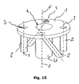
- a ground anchoring system G for various kind of objects, such as building structures, according to the present invention is in general shown with the reference number 100.
- the system comprises at least two elongated tubular guiding members 2, preferably three, inside which a respective anchoring rod 5 is inserted at a inserting end 21, the anchoring rod being at least twice long that the elongated members.
- the correct sizing of the rod 5 will be connected to the specific application and, by means of the present description, a person skilled in the art will be able to make this designing choices.
- the sizing of the supporting surface and of the anchoring rods will be substantially determined by two variables: the structure to be supported and the kind of bottom onto which performing the anchoring.
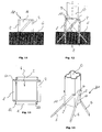
- the elongated members 2 has a closed cross section and are apt to define a inserting direction I, in which the anchoring rods 5 are inserted, as can be seen in figure 2 .
- the inserting directions I are tilted to a fixing direction F, substantially perpendicular to the ground G, as can be seen in figures 4 and 7 .
- the elongated members 2 are made as separated bodies fixed to the supporting surface 1, e.g. by means of welding.
- the supporting surface 1 has a substantially flat development, and has connecting means for connection to an object O to be anchored to the ground.
- such connecting means are formed by a central hole 4 onto which the object O can be fixed.
- the elongated members 2 are designed such that they have a longitudinal extension at least equal to about the distance D between two adjoining inserting ends 21.
- the tubular members 2 and the supporting surface will be placed at least partially above ground G in use.
- Such distance D can be simply defined as the length of the shortest segment allowing to connect the inserting ends 21 of two elongated members 2.
- the elongated members 2 has a tilting such that the exit end 22 is placed at a greater distance from the axis defining the fixing direction F than the inserting end 21.
- the elongated members 2 develops from the holes 3 of the plate 1 according to a substantially radial direction.
- the elongated guiding members 2 will have the function of directing the anchoring rods 5 during their penetration in the ground G.
- the members for the rods could be welded to the surface 1 with a predetermined tilting, that will be anyhow non-zero relative to the axis of the surface 1 corresponding with the axis F.
- the figure 5 is explanatory, showing the installation to a bottom by a bidimensional representation.
- the anchoring rods 5 are inserted inside the elongated members 2 and moves down towards the ground by means of a mechanical thrust, passing through the structure 1 with obliquity determined by the members 2, as can be seen in figure 4 .
- the members 2 form an integral part of the structure itself, their tilting to the axis defined by the fixing direction F finally determining poi the clamping of the object and that can be welded in order to direct to the insert with any tilt different from the one of the above mentioned axis.
- the simple opposition of the inserting directions of the anchoring rods provides that once all of the them are installed in their seats the escape thereof is not possible for any direction of the mechanical force exerted on the base.
- the system provides a sort of joint capable of opposing to the mechanical stress determined by the result of the opposed forces holding the anchoring rods to the ground.
- the mechanical forces exerted by the object O anchored on the surface 1 and the forces that in turn load it are discharged on the mass into which the rods are immersed. Then the hold of the anchoring will be effective until when the ground or the objects yields. Obviously, the greater the cohesion of the material forming the ground is and the stronger the materials with which the object is realized are, the more effective will be the anchoring.
- Figure 5 shows in a extremely simplified manner as a pressure on the surface 1 opposes to the penetration strength of the ground by the surface of the obliquely placed rods.
- figure 6 shows as a force exerted along the axis of the supporting surface 1 in an opposed direction to the ground opposes to the mass urging above the anchoring rods 5.
- figure 7 it is shown a vertical development object O fixed to the supporting surface 1 by the central hole 4.
- a force exerted perpendicularly to the vertical structure generates a rotation effect determined by the mechanical moment between rods, surface, object and ground.
- a kind of composition of the effects of figures 5 and 6 varying relative to axis F of the supporting surface 1 will oppose to the movement. From the side from which the lateral pressure is provided there will be a similar effect to the one of figure 6 , i.e. the pressure of the bottom on the anchoring rods moving down obliquely in such direction will oppose.
- the supporting surface 11 corresponds to a lateral surface of a hollow supporting structure 10, in particular box shaped.
- the supporting surface 11 will be substantially perpendicular to the ground G in use, unlike the previous case.
- the supporting structure 10 is parallelepiped shaped, wherein the lateral surfaces correspond to a lateral faces of the parallelepiped. Then, the elongated members 2, preferably fixed by welding to the faces 11, will extend substantially between two opposed vertexes of such faces 11, so as to advantageously provide a great stability to the structure, the size thereof being minimal.
- such embodiment could be advantageously used as a base for the supporting leg for a gazebo in a garden, ad a post per the signs in a public garden or on the road.
- the supporting structure 10 corresponds to a end portion of the object O, and, as a consequence, the elongated members 2 are directly fixed to the end portion of the object O.
- the plate 1 comprises a elongated hollow fixing member 41, placed at the opening 4 forming the central hole.
- Te fixing member 41 extends substantially parallel to the fixing direction F and can house therein a portion of the object O, formed e.g. by the end portion of a post.
- the elongated members 2 develops from said holes 3 in the plate 1 according to a substantially tangential direction.
Landscapes
- Engineering & Computer Science (AREA)
- Structural Engineering (AREA)
- Civil Engineering (AREA)
- Architecture (AREA)
- Life Sciences & Earth Sciences (AREA)
- General Life Sciences & Earth Sciences (AREA)
- Mining & Mineral Resources (AREA)
- Paleontology (AREA)
- General Engineering & Computer Science (AREA)
- Piles And Underground Anchors (AREA)
- Foundations (AREA)
- Reinforcement Elements For Buildings (AREA)
Applications Claiming Priority (2)
| Application Number | Priority Date | Filing Date | Title |
|---|---|---|---|
| IT000091A ITPD20090091A1 (it) | 2009-04-16 | 2009-04-16 | Dispositivo di ancoraggio rapido ad inserti obliqui |
| PCT/IB2010/051670 WO2010119432A2 (en) | 2009-04-16 | 2010-04-16 | Anchoring system |
Publications (2)
| Publication Number | Publication Date |
|---|---|
| EP2419585A2 EP2419585A2 (en) | 2012-02-22 |
| EP2419585B1 true EP2419585B1 (en) | 2016-03-30 |
Family
ID=41557502
Family Applications (1)
| Application Number | Title | Priority Date | Filing Date |
|---|---|---|---|
| EP10723779.4A Active EP2419585B1 (en) | 2009-04-16 | 2010-04-16 | Anchoring system |
Country Status (11)
| Country | Link |
|---|---|
| US (1) | US8561361B2 (pl) |
| EP (1) | EP2419585B1 (pl) |
| JP (1) | JP5539495B2 (pl) |
| KR (1) | KR20120021305A (pl) |
| CN (1) | CN102395738A (pl) |
| ES (1) | ES2578978T3 (pl) |
| HU (1) | HUE029325T2 (pl) |
| IT (1) | ITPD20090091A1 (pl) |
| PL (1) | PL2419585T3 (pl) |
| RU (1) | RU2538555C2 (pl) |
| WO (1) | WO2010119432A2 (pl) |
Families Citing this family (35)
| Publication number | Priority date | Publication date | Assignee | Title |
|---|---|---|---|---|
| US8511020B2 (en) * | 2009-08-18 | 2013-08-20 | Crux Subsurface, Inc. | Composite cap |
| WO2012149670A1 (zh) * | 2011-04-30 | 2012-11-08 | 安徽省高速公路控股集团有限公司 | 根式基础锚碇施工方法及根键式钻孔灌注桩施工方法 |
| ES2662770T3 (es) * | 2011-06-28 | 2018-04-09 | Surefoot Systems International Limited | Placas de zapatas mejoradas |
| JP5425157B2 (ja) * | 2011-10-13 | 2014-02-26 | テック大洋工業株式会社 | 簡易基礎用構造体 |
| JP5631924B2 (ja) * | 2012-04-25 | 2014-11-26 | テック大洋工業株式会社 | 架台の設置方法 |
| US8601750B1 (en) * | 2012-06-04 | 2013-12-10 | Ip Power Holdings Limited | Method and apparatus for ground installation |
| WO2014014033A1 (ja) * | 2012-07-20 | 2014-01-23 | 伊藤組土建株式会社 | 杭基礎および杭基礎設置方法 |
| ITMO20120265A1 (it) | 2012-10-31 | 2014-05-01 | Guido Bardelli | Sistema di ancoraggio di oggetti in terreni |
| JP5896529B2 (ja) * | 2012-11-27 | 2016-03-30 | 大成建設株式会社 | 基礎構造 |
| US9739070B2 (en) | 2013-01-10 | 2017-08-22 | Kevin M. Bushore | Methods and apparatuses of supporting and bracing a utility pole |
| US9103090B2 (en) * | 2013-01-10 | 2015-08-11 | Kevin M. Bushore | Methods and apparatuses of supporting and bracing a pole |
| GB2512065A (en) * | 2013-03-18 | 2014-09-24 | Mccue Internat Inc | Ground reinforcement bracket |
| CN103174136A (zh) * | 2013-03-26 | 2013-06-26 | 周卫 | 抓地装置 |
| JP6033806B2 (ja) * | 2014-03-03 | 2016-11-30 | テック大洋工業株式会社 | 支柱固定方法及びそれに用いられる固定具 |
| CN104895075B (zh) * | 2015-04-15 | 2016-08-17 | 广东省建筑工程集团有限公司 | 一种靶站密封筒锚杆精确安装方法 |
| RU2596618C1 (ru) * | 2015-08-07 | 2016-09-10 | Федеральное государственное бюджетное образовательное учреждение высшего образования "Национальный исследовательский Московский государственный строительный университет" (НИУ МГСУ) | Анкерное крепление |
| US9828739B2 (en) | 2015-11-04 | 2017-11-28 | Crux Subsurface, Inc. | In-line battered composite foundations |
| JP6795354B2 (ja) * | 2016-08-31 | 2020-12-02 | 東日本旅客鉄道株式会社 | 支柱の立設装置 |
| US11078641B2 (en) * | 2017-11-06 | 2021-08-03 | Richard J. Gagliano | Foundation integral construction components and support systems |
| CN107989028B (zh) * | 2017-12-01 | 2023-08-01 | 徐少钢 | 一种便携式机械组合地上固定桩装置 |
| CN108708673B (zh) * | 2018-04-04 | 2021-04-02 | 哈尔滨工业大学 | 基于多机械臂着陆及叉形超声波钻进的小行星表面附着锚定装置 |
| CN109057516A (zh) * | 2018-07-23 | 2018-12-21 | 朱程航 | 一种牢固的户外帐篷用地钉 |
| PL427071A1 (pl) * | 2018-10-19 | 2020-04-20 | Wójcikowski Adam | Kotwa gruntowa |
| NZ751765A (en) * | 2019-04-02 | 2020-02-28 | Kiwi Patents Ltd | A post |
| CN110005246B (zh) * | 2019-04-19 | 2021-06-15 | 国家电网有限公司 | 架空线电杆防倒定位装置以及定位方法 |
| JP6604526B1 (ja) * | 2019-06-21 | 2019-11-13 | 匡伯 河邉 | ソーラーパネル用の架台支柱の固定具、及び、その使用方法 |
| US11828038B2 (en) | 2020-07-10 | 2023-11-28 | Dale Clayton Miller | Pile connection for horizontally fixing an elongated beam for a foundation support system |
| US20220042273A1 (en) * | 2020-07-14 | 2022-02-10 | Mark Anthony S. Dimitrijevic | Structural support and stabilization assemblies and methods for installing same |
| US11841169B2 (en) * | 2020-09-17 | 2023-12-12 | Ojo, Inc. | Tracker motor support for truss foundations |
| DE202020105707U1 (de) * | 2020-10-05 | 2020-11-10 | Düllmann Umformtechnik GmbH | Photovoltaikanlage zur Verankerung im Erdreich |
| RU202013U1 (ru) * | 2020-10-06 | 2021-01-27 | Общество с ограниченной ответственностью «Виннер Марин» | Опорная свайная площадка |
| US11788246B2 (en) | 2020-12-14 | 2023-10-17 | Dale Clayton Miller | Micropile connection for supporting a vertical pile |
| US20230035050A1 (en) * | 2021-06-23 | 2023-02-02 | 65 Innovations BV | Multi-spike fence post anchor |
| US11619063B1 (en) * | 2022-01-28 | 2023-04-04 | Walter Williams | Pole stand |
| US11933014B2 (en) | 2022-05-02 | 2024-03-19 | Gary Gale | Reticulated driven micropile footing system |
Family Cites Families (25)
| Publication number | Priority date | Publication date | Assignee | Title |
|---|---|---|---|---|
| DE823336C (de) | 1950-07-14 | 1952-11-17 | Wilhelm Francois | Bodenanker fuer waagerechte und lotrechte Zugbeanspruchung |
| US2826281A (en) * | 1954-03-09 | 1958-03-11 | Albert C Green | Support or anchors for vertical columns or the like |
| US3809346A (en) * | 1973-02-02 | 1974-05-07 | R Jackson | Fence post support |
| US3903662A (en) * | 1973-05-17 | 1975-09-09 | Jury Alexandrovich Gabliya | Method of securing structural support elements in soil |
| US4452018A (en) * | 1980-07-01 | 1984-06-05 | Hill Claud A | Device for anchoring a building |
| US4455795A (en) * | 1981-02-11 | 1984-06-26 | Cole Robert F | Post anchoring device |
| FR2639392B1 (fr) * | 1988-11-18 | 1997-04-30 | Liesse Maurice | Procede d'ancrage et de scellement par etais traversiers de fouissage |
| US5104074A (en) * | 1989-06-23 | 1992-04-14 | Malloy James T | Fence support |
| US5039256A (en) * | 1990-03-15 | 1991-08-13 | Richard Gagliano | Pinned foundation system |
| US5065975A (en) * | 1990-11-05 | 1991-11-19 | Homer Giles | Mail box support apparatus |
| US5243795A (en) * | 1991-09-20 | 1993-09-14 | Bruce Roberts | Tie down stake |
| US5377944A (en) * | 1992-07-07 | 1995-01-03 | Par Financial Services, Inc. | Flag holder |
| US5873679A (en) * | 1996-11-12 | 1999-02-23 | Cusimano; Matt | Seismic foundation pier with ground anchor means |
| US5791635A (en) * | 1997-01-13 | 1998-08-11 | Hull; Harold L. | Fence post with anchor |
| CN2296366Y (zh) * | 1997-01-23 | 1998-11-04 | 北京市第三城市建设工程公司 | 握线式可回收锚杆 |
| CN2357042Y (zh) * | 1998-12-29 | 2000-01-05 | 山西煤电(集团)有限责任公司 | 带有附属结构的锚固件 |
| FR2806747A1 (fr) | 2000-03-23 | 2001-09-28 | Dejoux Andre Marcel | Systeme d'ancrage simple ou multiple d'objets dans le sol |
| US6511034B2 (en) * | 2000-07-12 | 2003-01-28 | Think Inc. Enterprises | Temporary post support |
| US6591564B2 (en) * | 2001-10-10 | 2003-07-15 | Matt Cusimano | Ground-anchor brace system for modular buildings |
| JP2004143867A (ja) * | 2002-10-28 | 2004-05-20 | Minoru Kitagawa | 支柱とロープの支持装置と、その設置工法 |
| US7326003B2 (en) * | 2003-07-31 | 2008-02-05 | Gagliano Richard J | Surface structures and methods thereof |
| JP4437169B2 (ja) * | 2004-04-12 | 2010-03-24 | テック大洋工業株式会社 | 簡易基礎及び簡易基礎の集合体 |
| JP3916083B2 (ja) * | 2004-04-12 | 2007-05-16 | テック大洋工業株式会社 | 簡易基礎及び簡易基礎の集合体 |
| RU53312U1 (ru) * | 2006-01-10 | 2006-05-10 | Общество с ограниченной ответственностью "Институт "Проектмостореконструкция" | Ростверк мостовой опоры |
| JP4335958B2 (ja) | 2007-06-26 | 2009-09-30 | ミロモックル産業株式会社 | 簡易基礎 |
-
2009
- 2009-04-16 IT IT000091A patent/ITPD20090091A1/it unknown
-
2010
- 2010-04-16 RU RU2011146328/03A patent/RU2538555C2/ru active
- 2010-04-16 JP JP2012505291A patent/JP5539495B2/ja active Active
- 2010-04-16 HU HUE10723779A patent/HUE029325T2/en unknown
- 2010-04-16 WO PCT/IB2010/051670 patent/WO2010119432A2/en active Application Filing
- 2010-04-16 KR KR1020117027125A patent/KR20120021305A/ko not_active Application Discontinuation
- 2010-04-16 EP EP10723779.4A patent/EP2419585B1/en active Active
- 2010-04-16 PL PL10723779.4T patent/PL2419585T3/pl unknown
- 2010-04-16 ES ES10723779.4T patent/ES2578978T3/es active Active
- 2010-04-16 CN CN2010800172968A patent/CN102395738A/zh active Pending
- 2010-04-16 US US13/264,753 patent/US8561361B2/en active Active
Also Published As
| Publication number | Publication date |
|---|---|
| RU2011146328A (ru) | 2013-05-27 |
| RU2538555C2 (ru) | 2015-01-10 |
| EP2419585A2 (en) | 2012-02-22 |
| PL2419585T3 (pl) | 2016-10-31 |
| JP2012524186A (ja) | 2012-10-11 |
| JP5539495B2 (ja) | 2014-07-02 |
| ITPD20090091A1 (it) | 2010-10-17 |
| WO2010119432A2 (en) | 2010-10-21 |
| ES2578978T3 (es) | 2016-08-03 |
| US20120096778A1 (en) | 2012-04-26 |
| HUE029325T2 (en) | 2017-02-28 |
| CN102395738A (zh) | 2012-03-28 |
| US8561361B2 (en) | 2013-10-22 |
| KR20120021305A (ko) | 2012-03-08 |
| WO2010119432A3 (en) | 2011-04-21 |
Similar Documents
| Publication | Publication Date | Title |
|---|---|---|
| EP2419585B1 (en) | Anchoring system | |
| US5582492A (en) | Method and apparatus for an anchored earth restraining wall | |
| US7024827B2 (en) | Preconstruction anchoring system and method for buildings | |
| KR101530871B1 (ko) | 띠형 섬유보강재를 이용한 자연석 옹벽 구조물 및 그 시공방법 | |
| JP4812324B2 (ja) | 擁壁及びその施工方法 | |
| JP2007002629A (ja) | 基礎増設補強金物及び基礎増設補強方法 | |
| KR102170177B1 (ko) | 전주 근가 | |
| JP2787806B2 (ja) | 土留め擁壁 | |
| US20170121926A1 (en) | In-Line Battered Composite Foundations | |
| JP4060137B2 (ja) | 土木構造物及びその構築工法 | |
| JP3821296B2 (ja) | 組立式防火塀及びその施工方法 | |
| JPS6026724A (ja) | 鉄骨建築構造物と合成地中梁との一体化工法 | |
| KR20090112983A (ko) | 목질부재의 접합구조 | |
| KR200273555Y1 (ko) | 보강토 옹벽의 보강재 체결구조 | |
| KR20090098126A (ko) | 강도 보강용 합성 구조체 | |
| JP2005248596A (ja) | 建造物の基礎及びその施工方法 | |
| KR101795454B1 (ko) | 자립식 흙막이 시공공법 | |
| JP3492329B2 (ja) | 拡幅道路 | |
| JP2001342639A (ja) | 埋設型枠 | |
| AU2016203317B2 (en) | Ground Engaging Construction Support | |
| JPH0447021A (ja) | 山止め用親杭の施工方法 | |
| JPS60258326A (ja) | ポ−ルの建込み方法とその建込み用基礎 | |
| JP5215024B2 (ja) | 鋼製枠据え付け装置、土留め擁壁、および土留め擁壁の構築方法 | |
| JP2022047737A (ja) | 擁壁の施工方法 | |
| JPH10152853A (ja) | 地中構造物の構築工法及びこれに使用する構造部材 |
Legal Events
| Date | Code | Title | Description |
|---|---|---|---|
| PUAI | Public reference made under article 153(3) epc to a published international application that has entered the european phase |
Free format text: ORIGINAL CODE: 0009012 |
|
| 17P | Request for examination filed |
Effective date: 20111007 |
|
| AK | Designated contracting states |
Kind code of ref document: A2 Designated state(s): AT BE BG CH CY CZ DE DK EE ES FI FR GB GR HR HU IE IS IT LI LT LU LV MC MK MT NL NO PL PT RO SE SI SK SM TR |
|
| DAX | Request for extension of the european patent (deleted) | ||
| TPAC | Observations filed by third parties |
Free format text: ORIGINAL CODE: EPIDOSNTIPA |
|
| 17Q | First examination report despatched |
Effective date: 20141016 |
|
| GRAP | Despatch of communication of intention to grant a patent |
Free format text: ORIGINAL CODE: EPIDOSNIGR1 |
|
| INTG | Intention to grant announced |
Effective date: 20150928 |
|
| GRAS | Grant fee paid |
Free format text: ORIGINAL CODE: EPIDOSNIGR3 |
|
| GRAA | (expected) grant |
Free format text: ORIGINAL CODE: 0009210 |
|
| AK | Designated contracting states |
Kind code of ref document: B1 Designated state(s): AT BE BG CH CY CZ DE DK EE ES FI FR GB GR HR HU IE IS IT LI LT LU LV MC MK MT NL NO PL PT RO SE SI SK SM TR |
|
| REG | Reference to a national code |
Ref country code: GB Ref legal event code: FG4D |
|
| REG | Reference to a national code |
Ref country code: CH Ref legal event code: EP |
|
| REG | Reference to a national code |
Ref country code: AT Ref legal event code: REF Ref document number: 785601 Country of ref document: AT Kind code of ref document: T Effective date: 20160415 |
|
| REG | Reference to a national code |
Ref country code: IE Ref legal event code: FG4D |
|
| REG | Reference to a national code |
Ref country code: DE Ref legal event code: R096 Ref document number: 602010031701 Country of ref document: DE |
|
| REG | Reference to a national code |
Ref country code: FR Ref legal event code: PLFP Year of fee payment: 7 |
|
| REG | Reference to a national code |
Ref country code: RO Ref legal event code: EPE |
|
| REG | Reference to a national code |
Ref country code: LT Ref legal event code: MG4D |
|
| PG25 | Lapsed in a contracting state [announced via postgrant information from national office to epo] |
Ref country code: NO Free format text: LAPSE BECAUSE OF FAILURE TO SUBMIT A TRANSLATION OF THE DESCRIPTION OR TO PAY THE FEE WITHIN THE PRESCRIBED TIME-LIMIT Effective date: 20160630 Ref country code: HR Free format text: LAPSE BECAUSE OF FAILURE TO SUBMIT A TRANSLATION OF THE DESCRIPTION OR TO PAY THE FEE WITHIN THE PRESCRIBED TIME-LIMIT Effective date: 20160330 Ref country code: FI Free format text: LAPSE BECAUSE OF FAILURE TO SUBMIT A TRANSLATION OF THE DESCRIPTION OR TO PAY THE FEE WITHIN THE PRESCRIBED TIME-LIMIT Effective date: 20160330 |
|
| REG | Reference to a national code |
Ref country code: ES Ref legal event code: FG2A Ref document number: 2578978 Country of ref document: ES Kind code of ref document: T3 Effective date: 20160803 Ref country code: NL Ref legal event code: MP Effective date: 20160330 |
|
| REG | Reference to a national code |
Ref country code: AT Ref legal event code: MK05 Ref document number: 785601 Country of ref document: AT Kind code of ref document: T Effective date: 20160330 |
|
| PG25 | Lapsed in a contracting state [announced via postgrant information from national office to epo] |
Ref country code: LV Free format text: LAPSE BECAUSE OF FAILURE TO SUBMIT A TRANSLATION OF THE DESCRIPTION OR TO PAY THE FEE WITHIN THE PRESCRIBED TIME-LIMIT Effective date: 20160330 Ref country code: LT Free format text: LAPSE BECAUSE OF FAILURE TO SUBMIT A TRANSLATION OF THE DESCRIPTION OR TO PAY THE FEE WITHIN THE PRESCRIBED TIME-LIMIT Effective date: 20160330 Ref country code: SE Free format text: LAPSE BECAUSE OF FAILURE TO SUBMIT A TRANSLATION OF THE DESCRIPTION OR TO PAY THE FEE WITHIN THE PRESCRIBED TIME-LIMIT Effective date: 20160330 |
|
| PG25 | Lapsed in a contracting state [announced via postgrant information from national office to epo] |
Ref country code: NL Free format text: LAPSE BECAUSE OF FAILURE TO SUBMIT A TRANSLATION OF THE DESCRIPTION OR TO PAY THE FEE WITHIN THE PRESCRIBED TIME-LIMIT Effective date: 20160330 |
|
| REG | Reference to a national code |
Ref country code: GR Ref legal event code: EP Ref document number: 20160401315 Country of ref document: GR Effective date: 20160729 |
|
| REG | Reference to a national code |
Ref country code: EE Ref legal event code: FG4A Ref document number: E012379 Country of ref document: EE Effective date: 20160824 |
|
| PG25 | Lapsed in a contracting state [announced via postgrant information from national office to epo] |
Ref country code: IS Free format text: LAPSE BECAUSE OF FAILURE TO SUBMIT A TRANSLATION OF THE DESCRIPTION OR TO PAY THE FEE WITHIN THE PRESCRIBED TIME-LIMIT Effective date: 20160730 |
|
| PG25 | Lapsed in a contracting state [announced via postgrant information from national office to epo] |
Ref country code: AT Free format text: LAPSE BECAUSE OF FAILURE TO SUBMIT A TRANSLATION OF THE DESCRIPTION OR TO PAY THE FEE WITHIN THE PRESCRIBED TIME-LIMIT Effective date: 20160330 Ref country code: SK Free format text: LAPSE BECAUSE OF FAILURE TO SUBMIT A TRANSLATION OF THE DESCRIPTION OR TO PAY THE FEE WITHIN THE PRESCRIBED TIME-LIMIT Effective date: 20160330 Ref country code: PT Free format text: LAPSE BECAUSE OF FAILURE TO SUBMIT A TRANSLATION OF THE DESCRIPTION OR TO PAY THE FEE WITHIN THE PRESCRIBED TIME-LIMIT Effective date: 20160801 Ref country code: CZ Free format text: LAPSE BECAUSE OF FAILURE TO SUBMIT A TRANSLATION OF THE DESCRIPTION OR TO PAY THE FEE WITHIN THE PRESCRIBED TIME-LIMIT Effective date: 20160330 Ref country code: SM Free format text: LAPSE BECAUSE OF FAILURE TO SUBMIT A TRANSLATION OF THE DESCRIPTION OR TO PAY THE FEE WITHIN THE PRESCRIBED TIME-LIMIT Effective date: 20160330 |
|
| REG | Reference to a national code |
Ref country code: CH Ref legal event code: PL |
|
| REG | Reference to a national code |
Ref country code: DE Ref legal event code: R097 Ref document number: 602010031701 Country of ref document: DE |
|
| REG | Reference to a national code |
Ref country code: IE Ref legal event code: MM4A |
|
| PG25 | Lapsed in a contracting state [announced via postgrant information from national office to epo] |
Ref country code: LI Free format text: LAPSE BECAUSE OF NON-PAYMENT OF DUE FEES Effective date: 20160430 Ref country code: DK Free format text: LAPSE BECAUSE OF FAILURE TO SUBMIT A TRANSLATION OF THE DESCRIPTION OR TO PAY THE FEE WITHIN THE PRESCRIBED TIME-LIMIT Effective date: 20160330 Ref country code: CH Free format text: LAPSE BECAUSE OF NON-PAYMENT OF DUE FEES Effective date: 20160430 |
|
| PLBE | No opposition filed within time limit |
Free format text: ORIGINAL CODE: 0009261 |
|
| STAA | Information on the status of an ep patent application or granted ep patent |
Free format text: STATUS: NO OPPOSITION FILED WITHIN TIME LIMIT |
|
| REG | Reference to a national code |
Ref country code: HU Ref legal event code: AG4A Ref document number: E029325 Country of ref document: HU |
|
| 26N | No opposition filed |
Effective date: 20170103 |
|
| REG | Reference to a national code |
Ref country code: FR Ref legal event code: PLFP Year of fee payment: 8 |
|
| PG25 | Lapsed in a contracting state [announced via postgrant information from national office to epo] |
Ref country code: SI Free format text: LAPSE BECAUSE OF FAILURE TO SUBMIT A TRANSLATION OF THE DESCRIPTION OR TO PAY THE FEE WITHIN THE PRESCRIBED TIME-LIMIT Effective date: 20160330 Ref country code: IE Free format text: LAPSE BECAUSE OF NON-PAYMENT OF DUE FEES Effective date: 20160416 |
|
| REG | Reference to a national code |
Ref country code: FR Ref legal event code: PLFP Year of fee payment: 9 |
|
| PG25 | Lapsed in a contracting state [announced via postgrant information from national office to epo] |
Ref country code: CY Free format text: LAPSE BECAUSE OF FAILURE TO SUBMIT A TRANSLATION OF THE DESCRIPTION OR TO PAY THE FEE WITHIN THE PRESCRIBED TIME-LIMIT Effective date: 20160330 |
|
| PG25 | Lapsed in a contracting state [announced via postgrant information from national office to epo] |
Ref country code: MC Free format text: LAPSE BECAUSE OF FAILURE TO SUBMIT A TRANSLATION OF THE DESCRIPTION OR TO PAY THE FEE WITHIN THE PRESCRIBED TIME-LIMIT Effective date: 20160330 Ref country code: MT Free format text: LAPSE BECAUSE OF NON-PAYMENT OF DUE FEES Effective date: 20160430 Ref country code: LU Free format text: LAPSE BECAUSE OF NON-PAYMENT OF DUE FEES Effective date: 20160416 Ref country code: MK Free format text: LAPSE BECAUSE OF FAILURE TO SUBMIT A TRANSLATION OF THE DESCRIPTION OR TO PAY THE FEE WITHIN THE PRESCRIBED TIME-LIMIT Effective date: 20160330 |
|
| REG | Reference to a national code |
Ref country code: EE Ref legal event code: HC1A Ref document number: E012379 Country of ref document: EE |
|
| REG | Reference to a national code |
Ref country code: EE Ref legal event code: QB4A Ref document number: E012379 Country of ref document: EE Free format text: EXCLUSIVE LICENSE UNTIL 20211231 Name of requester: TREESYSTEM S.R.L., IT Effective date: 20190101 |
|
| PGFP | Annual fee paid to national office [announced via postgrant information from national office to epo] |
Ref country code: IT Payment date: 20221122 Year of fee payment: 14 |
|
| PGFP | Annual fee paid to national office [announced via postgrant information from national office to epo] |
Ref country code: RO Payment date: 20230411 Year of fee payment: 14 Ref country code: FR Payment date: 20230420 Year of fee payment: 14 Ref country code: ES Payment date: 20230627 Year of fee payment: 14 Ref country code: EE Payment date: 20230414 Year of fee payment: 14 Ref country code: DE Payment date: 20230420 Year of fee payment: 14 Ref country code: BG Payment date: 20230420 Year of fee payment: 14 |
|
| PGFP | Annual fee paid to national office [announced via postgrant information from national office to epo] |
Ref country code: TR Payment date: 20230414 Year of fee payment: 14 Ref country code: PL Payment date: 20230406 Year of fee payment: 14 Ref country code: HU Payment date: 20230421 Year of fee payment: 14 Ref country code: GR Payment date: 20230420 Year of fee payment: 14 |
|
| PGFP | Annual fee paid to national office [announced via postgrant information from national office to epo] |
Ref country code: BE Payment date: 20230419 Year of fee payment: 14 |
|
| PGFP | Annual fee paid to national office [announced via postgrant information from national office to epo] |
Ref country code: GB Payment date: 20230419 Year of fee payment: 14 |