EP2402219B1 - Parkhilfevorrichtung - Google Patents
Parkhilfevorrichtung Download PDFInfo
- Publication number
- EP2402219B1 EP2402219B1 EP10746051.1A EP10746051A EP2402219B1 EP 2402219 B1 EP2402219 B1 EP 2402219B1 EP 10746051 A EP10746051 A EP 10746051A EP 2402219 B1 EP2402219 B1 EP 2402219B1
- Authority
- EP
- European Patent Office
- Prior art keywords
- parking
- vehicle
- guiding
- section
- driver
- Prior art date
- Legal status (The legal status is an assumption and is not a legal conclusion. Google has not performed a legal analysis and makes no representation as to the accuracy of the status listed.)
- Active
Links
Images


Classifications
-
- B—PERFORMING OPERATIONS; TRANSPORTING
- B62—LAND VEHICLES FOR TRAVELLING OTHERWISE THAN ON RAILS
- B62D—MOTOR VEHICLES; TRAILERS
- B62D6/00—Arrangements for automatically controlling steering depending on driving conditions sensed and responded to, e.g. control circuits
-
- B—PERFORMING OPERATIONS; TRANSPORTING
- B62—LAND VEHICLES FOR TRAVELLING OTHERWISE THAN ON RAILS
- B62D—MOTOR VEHICLES; TRAILERS
- B62D15/00—Steering not otherwise provided for
- B62D15/02—Steering position indicators ; Steering position determination; Steering aids
- B62D15/027—Parking aids, e.g. instruction means
- B62D15/0285—Parking performed automatically
-
- B—PERFORMING OPERATIONS; TRANSPORTING
- B60—VEHICLES IN GENERAL
- B60W—CONJOINT CONTROL OF VEHICLE SUB-UNITS OF DIFFERENT TYPE OR DIFFERENT FUNCTION; CONTROL SYSTEMS SPECIALLY ADAPTED FOR HYBRID VEHICLES; ROAD VEHICLE DRIVE CONTROL SYSTEMS FOR PURPOSES NOT RELATED TO THE CONTROL OF A PARTICULAR SUB-UNIT
- B60W10/00—Conjoint control of vehicle sub-units of different type or different function
- B60W10/20—Conjoint control of vehicle sub-units of different type or different function including control of steering systems
-
- B—PERFORMING OPERATIONS; TRANSPORTING
- B60—VEHICLES IN GENERAL
- B60W—CONJOINT CONTROL OF VEHICLE SUB-UNITS OF DIFFERENT TYPE OR DIFFERENT FUNCTION; CONTROL SYSTEMS SPECIALLY ADAPTED FOR HYBRID VEHICLES; ROAD VEHICLE DRIVE CONTROL SYSTEMS FOR PURPOSES NOT RELATED TO THE CONTROL OF A PARTICULAR SUB-UNIT
- B60W30/00—Purposes of road vehicle drive control systems not related to the control of a particular sub-unit, e.g. of systems using conjoint control of vehicle sub-units, or advanced driver assistance systems for ensuring comfort, stability and safety or drive control systems for propelling or retarding the vehicle
- B60W30/06—Automatic manoeuvring for parking
Definitions
- the present invention relates to a parking assist apparatus for causing a vehicle to be parked by an automatic steering.
- an automatic steering parking assist system configured to cause a monitor mounted inside a vehicle to display a view rearwardly of the vehicle body and to effect an automatic steering with utilization of an electrically powered steering (EPS) as an actuator.
- EPS electrically powered steering
- a journal of Society of Automotive Engineers of Japan includes a thesis introducing such system, entitled: "Development of Intelligent Parking Assist' (Non-Patent Document 1).
- a driver after switching the shift lever into reverse, uses buttons shown on a touch panel of a monitor to effect setting of e.g. a mode of parking, a parking target position, etc. Specifically, the mode of parking, whether a garage parking or a parallel parking is selected by a selection button on the touch panel. Then, the user will adjust the parking target position shown in a superposed manner on the monitor and then finally presses an OK button on the touch panel to start the parking assist.
- Non-Patent Document 1 attempts are made for improvement of the precision in the initial position of the parking target position, through recognition of parking stall delimiting lines by an image processing or recognition of a space available for parking with using a supersonic sensor.
- Non-Patent Document 1 Makino Yasushi, and three others,: “Development of Intelligent Parking Assist”, Journal of Society of Automotive Engineers of Japan”, Society of Automotive Engineers of Japan, Vol. 60, No. 10, 2006, p.47-52 .
- Document EP 1 873 013 A1 discloses according to the preamble of claim 1 a parking assistance device including a target position setting device and a steering assistance portion.
- the steering assistance portion starts a steering assistance by an automatic steering when it is determined that the relationship between a first candidate of the target position, calculated according to a measuring result of a distance meter, and a second candidate of the target position, calculated according to an imaging result of an imager, meets a given condition.
- a parking assist apparatus comprises:
- the guiding start determining section determines whether a guiding possible state has been established or not. Further, this guiding start determining section causes the guiding section to start the guiding of the vehicle.
- the guiding start determining section effects the above determination of establishment of the guide possible sate, provided the preconditions of successful establishment of the guiding path and realization of the non-holding state are met.
- the guiding section of the parking assist apparatus of the present invention is configured to guide the vehicle to the parking target position by the automatic steering after the vehicle has advanced to said guiding start position by an operation of the driver and stopped there temporarily. If the vehicle makes a temporary stop at the guiding start position, the setting operation of the parking target position and the calculation of the guiding path can be effected with high precision. Further, such temporary stop makes it easier for the driver to create the non-holding state of not holding the steering device at the time of start of guiding.
- the parking assist apparatus of the present invention further comprises a moving state determining section for determining whether the vehicle is currently moving or not; and said guiding start determining section determines that a guiding possible state is established, provided a guiding path has been established and the non-holding state has been realized and the moving state determining section has determined that the vehicle is now stopped.
- said guiding start determining section is configured to cause the guiding section to start the guiding of the vehicle, after and provided the moving state determining section determines that the vehicle is currently moving.
- the driver based upon the conditions of establishment of the guiding path, the driver not holding the steering device and the vehicle is now moving because the driver has released the brake or the like, it can be determined with clarity that the driver has positively or knowingly transferred the vehicle control to the control system such as the guiding section.
- the vehicle can be parked smoothly by the automatic steering.
- at the time of determining that the driver has positively transferred the vehicle control to the control system such as the guiding section it is preferred that the vehicle is now under the stopped state. Therefore, advantageously, the determination of the guiding possible state prior to the start of the guide is made on the condition of the vehicle being stopped, in addition to the conditions of the establishment of the guiding path and realization of the non-holding state.
- the parking target position setting section of the parking assist apparatus of the invention is configured to set the parking target position within a predetermined region set as a part of the area of the parking position information; and the setting position of this predetermined region set according to the vehicle position information is varied in accordance with a driver's operation of the steering device.
- the driver When the parking target position is set, the driver is operating the steering device. Therefore, until establishment of a guiding path, the driver will keep operating the steering device. That is, when a guiding path has been established and the possibility of automatic steering is reported, the driver will still be holding the steering device. Then, if the driver now stops holding the steering device in response to a message reporting the possibility of automatic steering, the non-holding state determining section can determine with greater reliability and clarity that the steering device has now become free.
- said predetermined region is varied in accordance with the driver's operation of the steering device while the vehicle is stopped temporarily at the guiding start position. If the vehicle makes a temporary stop, it is possible to effect the setting of the parking target position within the predetermined region and the calculation of the guiding path to this parking target position with higher precision.
- the parking target position setting section of the parking assist apparatus of the invention is configured to set sequentially the parking target position relative to said predetermined region which area is varied sequentially in response to the operation of the steering device by the driver; said guiding path calculating section calculates the guiding path sequentially for the sequentially set parking target position; and said reporting information outputting section outputs reporting information urging the driver to stop the operation of the steering device, in addition to the reporting information reporting the automatic steering being now possible.
- the setting of the parking target position and the calculation of the guiding path to this parking target position are effected in accordance with the predetermined region which is varied sequentially/continuously in response to the driver's operation of the steering device. Therefore, in order to maintain a guiding path once successfully established, it is desired that the driver's operation of the steering device be stopped as soon as possible upon the establishment of the guiding path. Then, in response to an output of the reporting information urging the driver to stop the operation of the steering device, the driver can stop his/her operation of the steering device immediately.
- the reporting information is displayed in a superposed manner with a photographic image of a view surrounding the vehicle on a display device which displays the surrounding view photographic image captured by at least one photographic device mounted on the vehicle, and said reporting information includes information of a graphic image indicating said parking target position.
- said parking position information is photographic image information of a view surrounding the vehicle captured by at least one photographic device mounted on the vehicle.
- a photographic (image pickup) device is often mounted in a vehicle for the purpose of monitoring of the surrounding, etc. Therefore, the parking assist apparatus can be formed with utilization of photographic image, without providing any additional device or unit.
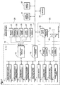
- the parking assist apparatus of the present invention is provided for parking a vehicle 30 by an automatic steering and includes an ECU (Electronic Control Unit) 10 as its principal component in the instant embodiment.
- the ECU 10 includes a microprocessor, a DSP (Digital Signal Processor), a memory, and various other electronic components.
- the ECU 10 includes a plurality of functional sections. These respective functional sections are realized by means of hardware, software or combination thereof, hence, these sections need not necessarily be comprised of individual components.
- a monitor device 33 having a display section 34 with a touch panel 36 formed thereon.
- the monitor device 33 is the liquid crystal type device having backlight. Needless to say, the monitor device 33 can also be a plasma display type or a CRT type.
- the touch panel 36 is a pressure-sensitive type or electrostatic type instruction inputting device capable of outputting a touched position touched by a finger or the like as location data.
- the monitor device 33 incorporates a speaker 35. However, the speaker 35 can be provided at a different position such as a position inside the door of the vehicle. Incidentally, it will be advantageous and convenient if a display unit included in a navigation system or the like is used also as this monitor device 33.
- a camera 32 is mounted at the rear end of the vehicle 30.
- This camera 32 is a digital camera including image pickup devices such as a CCD (Charge Coupled Device) or CIS (CMOS image sensor) and the camera 32 outputs information of captured image as time-series video image information.
- the camera 32 has a wide-angled lens, so that a view angle from 120 to 140 degrees in the horizontal direction is ensured. Also, this camera 32 is mounted on the vehicle 30 with a tilting of about 30 degrees relative to the optical axis, so that the camera can capture an image of the rear extending about 8 m rearwardly of the vehicle 30.
- the camera 32 for capturing an image rearwardly of the vehicle 30 can mount only a camera for capturing an image forwardly of the vehicle 30 or can mount two cameras for capturing images forwardly and rearwardly of the vehicle 30, respectively. Further, in addition to the above, the vehicle can mount also cameras for capturing images laterally of the vehicle, so that the image of the entire periphery of the vehicle 30 can be captured.
- the vehicle 30 mounts various sensors or switches as vehicle behavior detecting means 20 for detecting "behaviors" of the vehicle 30 such as a driving operation and moving states of the vehicle 30.
- the ECU 10 receives results of detection by the vehicle behavior detecting means 20 and the various functional sections of the ECU 10 effect various decisions, calculations, controls, based on the detection results inputted via a sensor input interface 18,
- a steering wheel 41 (“a steering device”) includes, in its operational line, a steering sensor 21 for determining an operational direction, an operational amount, an operational torque, etc. of the steering wheel 41 provided by the driver.
- the steering sensor 21, as well-known, is comprised of e.g. a magnetoresistance element, a torsion bar, or the like. Based on detection result from the steering sensor 21, the ECU 10 can determine also whether the driver is currently holding the steering wheel 41 or not.
- the vehicle 30 mounts an EPS (Electric Power Steering) system as a power steering system 31. The amount of steering provided by this EPS system too is detected by the steering sensor 21 and the EPS system executes feedback control.
- EPS Electronic Power Steering
- a traveling wheel speed sensor 23 for determining rotation of at least one wheels 38 of front wheels 38f and rear wheels 38r.
- the traveling wheel speed sensor 23 is constituted from a magnetoresistance element or the like. Based on detection result of the traveling wheel speed sensor 23, the ECU 10 can determine also whether the vehicle 30 is currently stopped or not.
- the vehicle is the FF type vehicle wherein power from an engine 40 mounted at a forward portion of the vehicle is transmitted to the front wheels 38f via a speed changer mechanism 39 having a torque converter, a CVT (Continuously Variable Transmission), etc. As shown in Fig.
- the traveling wheel speed sensor 23 determines rotational amount of the front wheels 38f as drive wheels.
- the traveling wheel speed sensor 23 can be configured to determine rotational amount of the rear wheels 38r as driven wheels.
- the traveling wheel speed sensors 23 can be provided for all the wheels.
- the speed changer mechanism 39 can be configured to determine the movement amount of the vehicle 30 from the rotational amount of the drive line.
- the operational line of the shift lever 45 includes a shift lever switch 25.
- the ECU 10 is capable of determining a shift (lever) position.
- the shift lever switch 25 detects whether the shift lever 45 has been set to the reverse travel or not and transmits the result of this detection to the ECU 10.
- a brake sensor 27 is incorporated in an operational line of a brake pedal 47 which is operated for applying a braking force to a braking system 37 of the wheels 38, so that this sensor 27 is capable of detecting presence/absence of a braking operation and its operational amount.
- the braking system 37 is an electrically powered brake, a braking force can be applied to the vehicle 30 in accordance with a control of the ECU 10.
- an accelerator pedal 49 for controlling the traveling speed, there is incorporated an accelerator sensor 29, so that its operational amount can be determined.
- the camera 32, the monitor device 33, the power steering system 31 and the braking system 37 are connected via an onboard communication network such as a CAN (Controller Area Network) to a communication interface 19 of the ECU 10. And, these components function as described above, in cooperation with the respective functional sections of the ECU 10.
- CAN Controller Area Network
- the parking assist apparatus (ECU 10) of the invention includes, as the functional sections thereof, the image obtaining section (parking position information obtaining section) 1, a parking target position setting section 2, a guiding path calculating section 3, a reporting information outputting section 4, a non-holding state detecting section 5, a guiding section 6, a guiding start determining section 7, a movement state determining section 8, and an image outputting section 9.
- the ECU 10 includes also various storing means such as a memory, a disc device (hard disc, an optical, magnetic or magnet-optical disc, etc.). For instance, for temporary storage of a program to be executed by the microprocessor, obtained image data, the internal or external memory and/or the disc device are employed.
- a sync separation circuit for obtaining photographic image information from the camera 32, a sync separation circuit, a buffer, a frame memory, etc. will be employed. Further, for displaying to the monitor device 33, a graphic image or characters or the like will be superposed on the photographic image, in accordance with an instruction from the image outputting section 9. These graphic image, characters or the like will be generated by an image processing module 16 including a graphic rendering circuit, a superimposing circuit or the like. The specific arrangements like these are well-known, so detailed discussion thereof will be omitted herein.
- the parking assist apparatus of the present invention has the function of assisting a driving operation for parking the vehicle 30 at a predetermined parking position.
- a driving operation for parking the vehicle 30 at a predetermined parking position.
- the vehicle 30 will be driven forward to a "reverse drive start position" and then from this reverse drive start position, the vehicle 30 will be driven reverse to the parking position.
- the vehicle 30 will be first driven to a reverse drive start position and then from this reverse drive start position, the vehicle 30 will be driven reverse to the parking position.
- the driver drives the vehicle 30 forwardly to the reverse drive start position by operating the steering wheel 41. Then, at this reverse drive start position, upon receipt of a report to the effect that the automatic steering is now possible, the driver will let the parking assist apparatus take charge of the control for driving the vehicle 30 in reverse to park this vehicle 30 at the parking position.
- a parking assist involving the automatic steering will be explained.
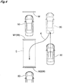
- Fig. 3 there will be explained an exemplary case of effecting a garage parking for a vacant parking stall E between other pre-parked (existing) vehicles 50 as a predetermined parking position E.
- the other vehicles 50 are also shown to clearly indicate the predetermined parking position. It is needless to say, however, that the operation does not require the presence of the other vehicles 50.
- the driver For a garage parking to the parking stall E, the driver first drives the vehicle 30 forwardly to the reverse drive start position. In doing this, the driver will be steering the vehicle 30 to the right side with manipulating the steering wheel 41. Therefore, when the drive stops the vehicle 30 at the reverse drive start position, in many cases, the front wheels 38f will be oriented to the right side as shown in Fig. 3 or the neutral position with the driver's operation with anticipation of the subsequent steering operation for garage parking. In this, if the driver shifts the shift lever 45 into the reverse position, the ECU 10 will cause the display section 34 of the monitor device 33 to display an image of the view rearwardly of the vehicle 30.
- the image obtaining section 1 obtains a photographic image from the camera 32 and effects, in an unillustrated image processing section, a correction operation thereon such as a distortion correction and the image outputting section 9 will output a predetermined graphic image in a superposed manner on the resultant photographic image.
- a correction operation thereon such as a distortion correction
- the image outputting section 9 will output a predetermined graphic image in a superposed manner on the resultant photographic image.
- the image displayed on the display section 34 of the monitor device 33 will be right/left mirror-image reversed. That is, the displaying will be effected in such a manner to provide a same visual effect as the case of the driver viewing the rear side of the vehicle 30 by the rear view mirror.
- the touch panel 36 will display such touch buttons as “garage parking”, “parallel parking”, “cancel assist”, etc. If the driver selects the touch button “garage parking”, parking assist for garage parking will be started.
- the message “start” in the flowchart of Fig. 5 corresponds to the start of this parking assist. That is, the touch buttons “garage parking”, “parallel parking”, “cancel assist” function not only as selection buttons for selecting respective parking modes at the time of parking assist, but also as start (or stop or cancel) buttons for the parking assist.
- the touch panel 36 first displays the touch button "start parking assist” and then displays, as parking mode selecting buttons, the touch buttons of "garage parking”, “parallel parking”.
- a mechanically operated or electrically operated button of "start parking assist” maybe provided separately on the console of the vehicle 30.
- the reporting information outputting section 4 issues a voice message via a voice processing module 17 and the speaker 35 for promoting the driver to designate a parking position (step #1 in Fig. 5 ).
- An example of such voice message is "Designate a parking position by operating steering wheel".
- the driver will operate the steering wheel 41 just like the case of manually parking the vehicle 30.
- the driver will operate the steering wheel 41 along the direction of arrow A for parking the vehicle 30 at the parking stall E.
- the front wheels 38f are steered to the direction of arrow B.
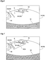
- this region of interest ROI corresponds to what is referred to herein as "a predetermined region” which is set when the parking target position setting section 2 obtains parking position information based on the driver's operation of the steering wheel 41.
- the region of interest ROI shown in Fig. 7 is a "concept" in the image processing, thus need not be displayed on the monitor device 33. However, this, if desired, may be displayed on the monitor device 33 for clear showing to the driver.
- the region of interest ROI is displayed on the monitor device 33. thus being illustrated as a right-left mirror image.
- an image of same orientation as a standard photographic image may be employed.
- the region of interest ROI is not limited to the particular form shown in Fig. 7 . Instead, it can be set in the form shown in Fig. 8 .
- the ECU 10 can limit the types of region of interest for image processing.
- the parking target position is set based on recognition of stall delimiting lines W (W1, W2) by the image processing. Therefore, the photographic image information obtained through the camera 32 correspond to parking position information relating to a position where the vehicle 30 is to be parked. Further, the image obtaining section 1 for obtaining the photographic image information corresponds to a parking position information obtaining section for obtaining parking position information.
- the parking target position setting section 2 effects recognition process for the stall delimiting lines W on the region of interest ROI as the target region for image processing and sets a parking target position. As the target area for image processing is limited, it becomes possible to restrict the possibility of other lines or object being erroneously recognized as the stall delimiting lines W, thus improving the recognition rate.
- the parking stall E delimited by the stall delimiting lines W is generally standardized and depending on the mode of parking, the relationship between the vehicle 30 and the parking position too can usually be specified. Therefore, the region of interest ROI can be set effectively.
- the parking target position setting section 2 effects an image processing on the region of interest (predetermined region) to detect the stall delimiting lines W, thus recognizing the parking stall E (step #2 in Fig. 5 ). Then, as shown in Fig. 3 , a parking target position P2 is set within the parking stall E (step #4 in Fig. 5 ). Recognition of the parking stall E is carried out substantially in realtime manner, in accordance with the region of interest ROI which continuously varies in association with the operation of the steering wheel 41. In case the parking stall E cannot be recognized, including a case of inability to detect the stall delimiting lines W, the ECU 10 will continue to urge the driver to designate a parking position (step #3 in Fig. 5 ).
- the ECU 10 Upon successful recognition of the parking stall E, the ECU 10 causes the display section 36 to display a parking target area G as shown in Fig. 9 .
- the driver can learn that the parking stall E has been successfully recognized and the parking target position P2 has been established, so that the driver can now stop the operation of the steering wheel 41.
- this displaying can be effected through the image processing module 17 including a graphic rendering circuit, a superimposing circuit, etc., in response to an instruction from the reporting information outputting section 4 or the image outputting section 9.
- the parking target position setting section 2 extracts the stall delimiting lines W from the region of interest ROI by effecting an edge detection technique which per se is known. And, on the extracted stall delimiting line W, the parking target position setting section 2 effects direct recognition through execution of a calculating process such as a known Hough transform, RANSAC (RANdom SAmple Consensus). For recognizing a parking stall E including a curved form, a curve recognition process can be added.
- a calculating process such as a known Hough transform, RANSAC (RANdom SAmple Consensus).
- the parking target position P2 is set in correspondence with a predetermined reference Q of the vehicle 30. More particularly, the parking target position P2 is set at coordinates where the reference Q is positioned when the vehicle 30 is parked in the parking stall E. This reference Q can be set e.g. at the mid point of the axle of the rear wheels 38r of the vehicle 30. Then, the guiding path calculating section 3 calculates a guiding path K for guiding the vehicle 30 to the parking target position P2 set as above by automatic steering (step #5 in Fig. 5 ). In this embodiment, at the time when the parking target position P2 is set, the vehicle 30 is stopped at a point P1 shown in Fig. 3 . Then, based on this point P1 as the guiding start position (reverse drive start position), the guiding path K from the guiding start position P1 to the parking target position P2 will be calculated.
- the vehicle 30 mounts an EPS system as a power steering system 31. Then, with activation of the EPS system in accordance with an instruction from the ECU 10, automatic steering of the vehicle 30 is made possible.
- the actuator mounted in the EPS system has a significant friction coefficient between the front wheels 38f as the steering wheels and the ground surface, this actuator is not suitable for an operation under the stop condition which requires a large drive torque. For this reason, the automatic steering using the EPS system is carried out simultaneously with movement of the vehicle 30. Therefore, the guiding path calculating section 3 calculates the guiding path K while the vehicle 30 is being steered and moved.
- the driver has operated the steering wheel 41, simulating an actual garage parking operation.
- the front wheels 38f have been moved to the direction suitable for garage parking.
- the guiding path K can be obtained by the shortest possible route.
- the front wheels 38f have been steered in the opposite direction to the steering direction for garage parking or steered to the neutral position as shown in Fig. 3 .
- an additional reverse movement will be required until the realization of the proper steering angle for the garage parking.
- the guiding path K would be longer.
- the guiding path K can be shortest.
- the guiding path calculating section 3 Upon successful establishment of the guiding path K, the guiding path calculating section 3 reports this establishment of the guiding path K to the other functional sections by setting a flag in the program processing of the microcomputer (step #6 in Fig. 5 ). Alternatively, the guiding path calculating section 3 can directly communicate this to the reporting information outputting section 4. Then, the reporting information outputting section 4 will output the reporting information reporting establishment of the guiding path K and possibility of automatic steering to the displaying section 34 and/or the speaker 35 via the graphic rendering circuit or the voice synthesizing circuit (step #7 in Fig 5 ). The speaker 35 issues a voice message such as: "Parking assist is now possible. Remove your hands from the steering wheel and drive the vehicle in reverse slowly.”.
- the displaying section 34 displays guide lines L1-L4, touch buttons, etc.
- the guide lines L1 are vehicle width extension lines
- the guide line L2 is a rearward 5 meter indicator line shown in green color
- the guide line L3 is a rearward 3 meter indicator line shown in green color
- the guide line L4 is a rearward 1 meter caution line shown in red color.
- the examples of the touch buttons shown here are "cancel" button for canceling the parking assist, "target change” button for canceling the currently set parking target area G (parking target position P2).
- the guiding start determining section 7 determines that a guiding possible state of automatic steering possible has been established in case there exists a non-holding state where the driver, in response to the above message, has removed his/her hands from the steering wheel 41 and then causes the guiding section 6 to initiate the guiding (step #9, in Fig. 5 ).
- Existence of the non-holding state of the driver's not holding the steering wheel 41 is determined by the non-holding state determining section 5.
- the operational line of the steering wheel 41 includes the steering sensor 21 for controlling the EPS system.
- This steering sensor 21 can be comprised of a magnetoresistance element, a torsion bar, etc. and this sensor is capable of determining the direction, amount and torque of the operation of the steering wheel 41.
- the results of these determinations by the steering sensor 21 are transmitted to the ECU 10 as shown in Fig. 1 .
- various techniques are known such as determining whether the steering wheel 41 is under free state with utilizing the result of feedback control of the EPS system, the result of detection from the steering sensor 21.
- the non-holding state determining section 5 determines whether the driver is currently holding the steering wheel 41 or not, based on the determination result of the steering sensor 21.
- the power steering system 31 normally, plays a subordinate function of providing additional or assist torque to a driver's steering operation. In this case, when the guiding by the guiding section 6 is about to be initiated, the driver has rendered the steering wheel 41 free.
- the power steering system 31 plays a subjective or positive role in the steering. Namely, the initiation of guiding by the guiding section 6 means shifting from the operational mode in which the power steering system 31 provides the subordinate function of providing the assisting torque, to the further operational mode of the system 31 plays the subjective or positive function for steering the vehicle 30 by moving the steering wheels 38f.
- SBW Steer-By-Wire
- the guiding start determining section 7 could cause the guiding section 6 to initiate the guiding, upon establishment of the guiding path K and the existence of non-holding state of the steering wheel 41.
- the vehicle 30 will remain under the stopped state unless the driver releases the brake pedal 47. That is, the guiding will not be substantially started and a "waiting" state will occur.
- the guiding by the guiding section 6 can be initiated with additional consideration of result of determination whether the vehicle 30 is moving or not (step #10 in Fig. 5 ).
- This determination i.e. whether the vehicle 30 is currently moving or not is made by a moving state determining section 8, based on the results of detections by other vehicle behavior detecting means such as the brake sensor 27, the traveling wheel speed sensor 23.
- the stopped state of the vehicle 30 can be included as another "precondition" for the guiding initiation (step #8 in Fig. 5 ). That is, as shown in Fig. 5 , in case the guiding path K has been established and the vehicle 30 is currently stopped (#8) AND the steering wheel 41 is currently under the non-holding state (#9), there is provided a guiding initiation standby state. Then, when the vehicle 30 starts moving under this guiding initiation standby state (#10), the guiding section 6 will be caused to initiate the guiding. With this arrangement, even more reliable automatic steering can be realized.
- the parking stall E is image-recognized and the parking target position P2 is set. Then, the guiding path K to this set parking target position P2 is calculated. Therefore, at the time of establishment of the guiding path K and the determination of the automatic steering being now possible, the driver will still be holding the steering wheel 41. Then, in response to the message of reporting initiation of guiding, the driver will move his/her hands off the steering wheel 41. With this, the non-holding state determining section 5 can more clearly determine the steering wheel 41 being now free. That is, in this system, the driver's action of rendering the steering wheel 41 to the non-holding state is taken as the driver's manifestation of intent of "Start of automatic steering is now desired".
- the steering wheel 41 in this embodiment is an example of steering device capable of steering the vehicle 30 by a driver's positive operation. Therefore, the steering device as the object of determination by the non-holding state determining section 5 of existence or absence of non-holding state is not limited to the steering wheel 41.
- a stick-type steering device may be mounted. In the case of such vehicle, determination will be made whether such stick type steering device is under non-holding state or not. Further, the detection of non-holding sate of the steering device can be done, not only by the steering sensor 21 described above, but by a touch sensor (not shown) provided in the steering device.
- the parking stall W is detected as a parking reference, through image processing based on photographic image information obtained by the camera 32. And, the movement states of the vehicle are calculated by the various kinds of sensors 21-29 functioning as the vehicle behavior detecting means.
- the basic principle of image processing and the basic principle of calculation of moving states will be explained first.
- Fig. 11 is an explanatory diagram illustrating relationship between the world coordinate system (X, Y, Z) as the reference coordinate system and a camera coordinate system (x, y, z) as the coordinate system of the camera 31.
- Fig. 12 is an explanatory diagram illustrating relationship between the camera coordinate system (x, y, z) and an image coordinate system (u, v) of the photographic image.
- the world coordinate system and the camera coordinate system both are right-hand coordinate systems.
- the "right-hand coordinate system" means a system in which X (x), Y(y), Z(z) are determined one after another in accordance with one after another opening of the thumb, the index finger and the middle finger of the right hand.
- the image coordinate system (u, v) is a two-dimensional coordinate system which is distant by a focal distance (f) of the camera from the origin of the camera coordinate along the z-axis direction in a plane ⁇ (image plane) perpendicular to the z-axis in agreement with the optical axis of the camera coordinate as shown in Fig. 12 .
- the point of intersection between the image plane and the optical axis is the image center (O 1 ).
- the u-axis of the image coordinate system is parallel with the x-axis of the camera coordinate system and v-axis of the image coordinate system is parallel with the y-axis of the camera coordinate system.
- ⁇ represents the angle formed between the u-axis of the v-axis.
- the image coordinate system (u, v) is provided as an orthogonal coordinate system, so ⁇ is set as 90 degrees.
- the point M is subjected to a coordinate transformation (perspective transformation/viewpoint transformation) represented by the following formula (3) by the perspective camera matrix P as a point (m) in the image plane ⁇ .
- a coordinate transformation perspective transformation/viewpoint transformation
- the transformation matrix of a position between the camera coordinate system and the world coordinate system is a translation vector T (translation component)
- the transformation matrix relating to the posture is a rotation matrix R (rotation component)
- a matrix including internal parameters of the camera 32 such as the focal distance (f) of the camera
- the angle ⁇ of the u-v axis is a camera matrix A
- the perspective camera matrix P is composed of a plurality of matrices, if generalized, this is represented as a three-by-four projection camera matrix.
- the point M in the world coordinate system is transformed by the above formula (3) into the point (m) in the image coordinate system and can be superposed on the photographic image obtained by the camera 32 by the image outputting section 9.
- the coordinates of the parking target position P2 in the world coordinate system can be derived from the point in the image coordinate system.
- the parking target position P2 is located in the Y-Z plane of the world coordinate system shown in Fig. 11 , so the coordinates can be obtained with good precision from the image coordinate system.
- the calculation principle of the movement amount as one of movement states of the vehicle 30 will be explained.
- the following explanation will be made based on the assumption that the vehicle 30 is located in the Y-Z plane (road surface) of the world coordinate system.
- the detection results of the vehicle behavior detecting means such as the steering sensor 21 and the traveling wheel speed sensor 23 are transmitted to the ECU 10.
- the guiding path calculating section 3 and the guiding section 6 will calculate the moving states such as a position change of the vehicle 30.
- the above-described guiding path calculating section 3 calculates the guiding path K, based on e.g. a steering angle which can be provided by the power steering system 31 and a speed which can be provided by creeping of the vehicle.
- Fig. 13 illustrates the vehicle 30 which is traveling in reverse along an arcuate movement path having a radius C.
- the broken line in the figure represents the arc having the radius C.
- Fig. 13 (b) is a partially enlarged view of Fig. 13 (a) .
- the radius C can be obtained from the detection result of the steering sensor 21.
- the mark (ds) in the figure represents a small movement distance of the vehicle 30 in a small period of time.
- the small movement distance (ds) can be obtained from the detection result of the traveling wheel speed sensor 23.
- the movement amount of the vehicle 30 is calculated.
- a mark ⁇ in the formulae represented the cumulative movement distance.
- the guiding section 6 continuously guides the vehicle 30 until the point Q reaches the parking target position P2.
- the braking system 37 is an electrically powered braking system
- the braking system will apply a braking force in response to an instruction from the ECU 10, thus stopping the vehicle 30.
- the ECU 10 issues a message for stopping the vehicle 30 from the speaker 35 through the reporting information outputting section 4. That is, the ECU 10 will urge the driver to operate the brake pedal 47, so that the vehicle 30 will be stopped by a driver's operation.
- the guiding by the automatic steering will be initiated simply in response to the driver's stopping holding the steering wheel 41, without the driver's operation of the OK button or the guiding start button. Therefore, the automatic steering control can be initiated smoothly and there occurs no time loss due to e.g. such button operation. So, a parking operation of the vehicle 30 can be completed speedily. Further, the driver can use the parking assist apparatus without suffering any trouble such as a button operation, so that the convenience of the apparatus can be improved.
- this method is not limited to the one described in the foregoing embodiment.
- the parking target position P2 is set based on automatic recognition of the parking stall E which in turn is based on the image recognition of the stall delimiting lines W.
- the invention is not limited thereto.
- an arrangement of the driver's adjusting the position of parking target with use of the touch panel 3 will also be possible.
- the parking target area G displayed at a predetermined position can be adjusted and set by the driver's using an arrow button H.
- the information inputted in accordance with the driver's instruction is to correspond what is defined as "parking position information" in the context of the present invention.
- the invention is not limited to the method of detecting the parking stall E based on image recognition. Any other method or technique can be employed also, as a matter of course.
- the parking target position can be set with stopping the vehicle at a place where the vehicle is desired to be parked, that is, a predetermined stop position relative to the position to be parked. In this case, after the vehicle is stopped at the predetermined stop position and the driver gives an instruction for initiating parking assist, the parking target position will be set.
- a sonar or a laser can be used for detecting an obstacle, if any, present in the parking stall and the parking target area may be set in a vacant space (vacant parking stall). Further, with combining these techniques, an arrangement allowing some manual adjustment by the driver as shown in Fig. 14 will be advantageous, taking into consideration the possible case of the parking target position (parking target area) being offset.
- the parking target position information obtaining section 1 will obtain the information from a memory or a register storing therein the predetermined position relationship and information from the steering sensor 21 and the traveling wheel speed sensor 23 as the parking position information. Further, in the case of setting the parking target position based on detection of obstacle present in the parking stall with using a sonar, a laser, or the like, the detection results from the sonar or the laser will correspond to the "parking position information".
- the present invention is applicable to an ITS (Intelligent Transport System), such as a parking assist apparatus for parking a vehicle by automatic steering.
- ITS Intelligent Transport System
Landscapes
- Engineering & Computer Science (AREA)
- Transportation (AREA)
- Mechanical Engineering (AREA)
- Chemical & Material Sciences (AREA)
- Combustion & Propulsion (AREA)
- Automation & Control Theory (AREA)
- Steering Control In Accordance With Driving Conditions (AREA)
- Power Steering Mechanism (AREA)
- Image Processing (AREA)
- Image Analysis (AREA)
- Control Of Driving Devices And Active Controlling Of Vehicle (AREA)
- Traffic Control Systems (AREA)
Claims (9)
- Parkassistenzvorrichtung, mit:einem Parkpositionsinformationenbezugsabschnitt (1) zum Beziehen von Parkpositionsinformationen bezüglich einer Position, wo ein Fahrzeug (30) zu parken ist;einem Parkzielpositionseinstellabschnitt (2) zum Einstellen einer Parkzielposition basierend auf den Parkpositionsinformationen; undeinem Führungsbahnberechnungsabschnitt (3) zum Berechnen einer Führungsbahn zum Führen des Fahrzeugs (30) zu der Parkzielposition mittels automatischen Lenkens,gekennzeichnet durcheinen Berichtsinformationenausgabeabschnitt (4) zum Berichten eines Fahrers des Fahrzeugs (30), nach einer erfolgreichen Einrichtung einer Führungsbahn, dass ein automatisches Lenken nun möglich ist;einen Nicht-Haltezustandsbestimmungsabschnitt (5) zum Bestimmen, ob ein Nicht-Haltezustand des Fahrers zutrifft, bei dem eine Lenkeinrichtung nicht gehalten wird;einen Führungsabschnitt (6) zum Führen des Fahrzeugs (30) von einer Führungsstartposition zu der Parkzielposition mittels des automatischen Lenkens durch Steuern der Lenkeinrichtung; undeinen Führungsstartbestimmungsabschnitt (7), der konfiguriert ist um zu bestimmen, dass ein Zustand einer möglichen Führung eingerichtet ist, in dem das Fahrzeug (30) durch den Führungsabschnitt (6) mittels des automatischen Lenkens geführt werden kann, vorausgesetzt, dass die Führungsbahn eingerichtet wurde und der Nicht-Haltezustand realisiert wurde, und ebenso konfiguriert ist, um den Führungsabschnitt (6) zu bewirken, die Führung basierend auf dem Ergebnis der Bestimmung zu initiieren, ohne dass eine Operation des Fahrers an einem Operationsabschnitt mit einer OK-Taste und einer Führungsstarttaste erforderlich ist.
- Parkassistenzvorrichtung gemäß Anspruch 1, wobei der Führungsabschnitt konfiguriert ist, um das Fahrzeug (30) mittels des automatischen Lenkens auf die Parkzielposition zu führen, nachdem das Fahrzeug (30) durch eine Operation des Fahrers zu der Führungsstartposition vorgerückt ist und dort vorübergehend angehalten wurde.
- Parkassistenzvorrichtung gemäß Anspruch 1 oder 2, weiterhin mit:einem Bewegungszustandsbestimmungsabschnitt (8) zum Bestimmen, ob sich das Fahrzeug (30) gegenwärtig bewegt oder nicht; undwobei der Führungsstartbestimmungsabschnitt (7) bestimmt, dass ein Zustand einer möglichen Führung eingerichtet ist, vorausgesetzt, dass eine Führungsbahn eingerichtet wurde und der Nicht-Haltezustand realisiert wurde, und wenn der Bewegungszustandsbestimmungsabschnitt (8) bestimmt hat, dass das Fahrzeug (30) nun gestoppt ist.
- Parkassistenzvorrichtung gemäß Anspruch 3, wobei der Führungsstartbestimmungsabschnitt (7) konfiguriert um den Führungsabschnitt (6) zu bewirken, die Führung des Fahrzeugs (30) zu starten, nachdem und vorausgesetzt, dass der Bewegungszustandsbestimmungsabschnitt (8) bestimmt, dass sich das Fahrzeug (30) gegenwärtig bewegt.
- Parkassistenzvorrichtung gemäß einem der Ansprüche 1 bis 4, wobei der Parkzielpositionseinstellabschnitt (2) konfiguriert ist, um die Parkzielposition innerhalb einer vorbestimmten Region einzustellen, die als ein Teil des Gebiets der Parkpositionsinformationen eingestellt ist; und
die Einstellposition dieser vorbestimmten Region, die gemäß den Fahrzeugpositionierungsinformationen (30) eingestellt ist, wird gemäß einer Operation des Fahrers der Lenkeinrichtung variiert. - Parkassistenzvorrichtung gemäß Anspruch 5, wobei die vorbestimmte Region gemäß der Operation des Fahrers der Lenkeinrichtung variiert wird, während das Fahrzeug (30) vorübergehend an der Führungsstartposition gestoppt ist.
- Parkassistenzvorrichtung gemäß Anspruch 5 oder 6, wobei:der Parkzielpositionseinstellabschnitt (2) der Parkassistenzvorrichtung der Erfindung konfiguriert ist, um die Parkzielposition in Bezug auf die vorbestimmte Region, deren Gebiet als Reaktion auf die Operation des Fahrers der Lenkeinrichtung sequentiell verändert wird, sequentiell einzustellen;der Führungsbahnberechnungsabschnitt (3) die Führungsbahn sequentiell für die sequentiell eingestellte Parkzielposition berechnet; undder Berichtsinformationenausgabeabschnitt (4) Berichtsinformationen ausgibt, die den Fahrer auffordern, die Operation der Lenkeinrichtung zu stoppen, zusätzlich zu den Berichtsinformationen, die berichten, dass das automatische Lenken nun möglich ist.
- Parkassistenzvorrichtung gemäß einem der Ansprüche 1 bis 7, wobei die Berichtsinformationen auf eine überlagerte Weise über einem fotografischen Bild einer Umgebungsansicht des Fahrzeugs (30) auf einer Anzeigevorrichtung (34), die das fotografische Bild der Umgebungsansicht anzeigt, das von mindestens einer am Fahrzeug (30) angebrachten fotografischen Vorrichtung (32) aufgenommen wurde, angezeigt werden und
die Berichtsinformationen Informationen eines grafischen Bildes umfassen, das die Parkzielposition angibt. - Parkassistenzvorrichtung gemäß einem der Ansprüche 1 bis 8, wobei die Parkpositionsinformation eine fotografische Bildinformation einer das Fahrzeug (30) umgebenden Ansicht ist, die von mindestens einer am Fahrzeug (30) angebrachten fotografischen Vorrichtung (32) aufgenommen wird.
Applications Claiming Priority (2)
| Application Number | Priority Date | Filing Date | Title |
|---|---|---|---|
| JP2009043007A JP5403330B2 (ja) | 2009-02-25 | 2009-02-25 | 駐車支援装置 |
| PCT/JP2010/051221 WO2010098170A1 (ja) | 2009-02-25 | 2010-01-29 | 駐車支援装置 |
Publications (3)
| Publication Number | Publication Date |
|---|---|
| EP2402219A1 EP2402219A1 (de) | 2012-01-04 |
| EP2402219A4 EP2402219A4 (de) | 2017-10-18 |
| EP2402219B1 true EP2402219B1 (de) | 2019-06-05 |
Family
ID=42665380
Family Applications (1)
| Application Number | Title | Priority Date | Filing Date |
|---|---|---|---|
| EP10746051.1A Active EP2402219B1 (de) | 2009-02-25 | 2010-01-29 | Parkhilfevorrichtung |
Country Status (6)
| Country | Link |
|---|---|
| US (1) | US8816878B2 (de) |
| EP (1) | EP2402219B1 (de) |
| JP (1) | JP5403330B2 (de) |
| KR (1) | KR20110097902A (de) |
| CN (1) | CN102405154B (de) |
| WO (1) | WO2010098170A1 (de) |
Families Citing this family (70)
| Publication number | Priority date | Publication date | Assignee | Title |
|---|---|---|---|---|
| DE102009028261A1 (de) * | 2009-08-05 | 2011-02-10 | Robert Bosch Gmbh | Verfahren und Steuerung zur Kalibrierung einer automatisch lenkenden Einparkhilfe |
| JP5113881B2 (ja) * | 2010-06-03 | 2013-01-09 | 株式会社デンソー | 車両周辺監視装置 |
| DE102011112577A1 (de) * | 2011-09-08 | 2013-03-14 | Continental Teves Ag & Co. Ohg | Verfahren und Vorrichtung für ein Assistenzsystem in einem Fahrzeg zur Durchführung eines autonomen oder teilautonomen Fahrmanövers |
| DE102011113916A1 (de) * | 2011-09-21 | 2013-03-21 | Volkswagen Aktiengesellschaft | Verfahren zur Klassifikation von Parkszenarien für ein Einparksystem eines Kraftfahrzeugs |
| KR101316501B1 (ko) * | 2011-10-14 | 2013-10-10 | 현대자동차주식회사 | 메쉬형 공간 해석기법을 이용한 주차 공간 탐지방법 및 그 시스템 |
| KR101327736B1 (ko) * | 2011-12-23 | 2013-11-11 | 현대자동차주식회사 | Avm탑뷰 기반 주차지원 시스템 |
| DE102012001666A1 (de) | 2012-01-28 | 2013-08-01 | Audi Ag | Verfahren zum Lenken eines Fahrzeugs mittels eines Lenkassistenzsystems |
| KR20130094994A (ko) * | 2012-02-17 | 2013-08-27 | 현대모비스 주식회사 | 주차 가능 영역 변경 장치 및 그 방법 |
| DE102012101686A1 (de) * | 2012-03-01 | 2013-09-05 | Continental Teves Ag & Co. Ohg | Verfahren für ein Fahrerassistenzsystem zur autonomen Längs- und/oder Querregelung eines Fahrzeugs |
| KR101877570B1 (ko) * | 2012-04-04 | 2018-07-11 | 현대자동차주식회사 | Av 영상 기반의 주차위치 설정 장치 및 그 방법 |
| KR20130118116A (ko) * | 2012-04-19 | 2013-10-29 | 현대모비스 주식회사 | 자동 주차 보조 시스템에서 장애물 충돌 회피 장치 및 방법 |
| US8954241B2 (en) | 2012-08-10 | 2015-02-10 | Caterpillar Inc. | Mining truck spotting under a shovel |
| US20150307090A1 (en) * | 2012-12-13 | 2015-10-29 | Toyota Jidosha Kabushiki Kaisha | Parking assistance device |
| JP6281178B2 (ja) * | 2013-01-31 | 2018-02-21 | 住友ベークライト株式会社 | 電子装置、自動車および電子装置の製造方法 |
| CN105246744A (zh) | 2013-05-29 | 2016-01-13 | 丰田自动车株式会社 | 驻车支援装置 |
| KR102062923B1 (ko) * | 2013-06-12 | 2020-01-06 | 현대모비스 주식회사 | 주차지원시스템 |
| JP6032363B2 (ja) | 2013-06-26 | 2016-11-24 | トヨタ自動車株式会社 | 駐車支援装置 |
| KR20150042106A (ko) * | 2013-10-10 | 2015-04-20 | 현대자동차주식회사 | 차량의 변속 장치 |
| JP6120371B2 (ja) * | 2013-10-23 | 2017-04-26 | クラリオン株式会社 | 自動駐車制御装置および駐車支援装置 |
| DE102013224539A1 (de) * | 2013-11-29 | 2015-06-03 | Bayerische Motoren Werke Aktiengesellschaft | Verfahren, Vorrichtung, Computerprogramm und Computerprogrammprodukt zur Bilddatenübertragung |
| KR102175961B1 (ko) * | 2013-11-29 | 2020-11-09 | 현대모비스 주식회사 | 차량 후방 주차 가이드 장치 |
| KR101498976B1 (ko) * | 2013-12-19 | 2015-03-05 | 현대모비스(주) | 차량용 주차지원시스템 및 주차지원방법 |
| US9514366B2 (en) * | 2014-02-03 | 2016-12-06 | Xerox Corporation | Vehicle detection method and system including irrelevant window elimination and/or window score degradation |
| DE102014209227B4 (de) * | 2014-05-15 | 2022-03-17 | Ford Global Technologies, Llc | Parkassistenzsystem |
| US9631933B1 (en) | 2014-05-23 | 2017-04-25 | Google Inc. | Specifying unavailable locations for autonomous vehicles |
| US9436182B2 (en) * | 2014-05-23 | 2016-09-06 | Google Inc. | Autonomous vehicles |
| CN104015660A (zh) * | 2014-06-23 | 2014-09-03 | 镇江杭川机械制造有限公司 | 车辆视觉驻车系统 |
| CN104260722B (zh) * | 2014-09-23 | 2017-06-06 | 北京理工大学 | 一种自动泊车系统 |
| DE102014224077A1 (de) * | 2014-11-26 | 2016-06-02 | Robert Bosch Gmbh | Verfahren und Vorrichtung zum assistierten Führen eines Fahrzeugs |
| DE112015006332T5 (de) * | 2015-03-19 | 2017-11-30 | Mitsubishi Electric Corporation | Fahrzeugsteuergerät und Fahrzeugsteuerverfahren |
| KR102327345B1 (ko) * | 2015-07-14 | 2021-11-17 | 주식회사 만도모빌리티솔루션즈 | 주차제어시스템 및 그 제어방법 |
| JP2017024683A (ja) * | 2015-07-28 | 2017-02-02 | 株式会社ジェイテクト | 車両用操舵装置 |
| JP6547495B2 (ja) * | 2015-07-31 | 2019-07-24 | アイシン精機株式会社 | 駐車支援装置 |
| JP6264338B2 (ja) * | 2015-08-07 | 2018-01-24 | トヨタ自動車株式会社 | 車線維持支援装置 |
| DE102015216881A1 (de) * | 2015-09-03 | 2017-03-09 | Robert Bosch Gmbh | Verfahren und Vorrichtung zum fahrerlosen Führen eines Kraftfahrzeugs innerhalb eines Parkplatzes |
| DE102016211179A1 (de) * | 2015-09-08 | 2017-03-09 | Volkswagen Aktiengesellschaft | Verfahren und Vorrichtung zum Durchführen einer automatisierten Fahrt eines Fahrzeugs entlang einer bereitgestellten Trajektorie |
| US9809158B2 (en) * | 2015-09-29 | 2017-11-07 | Toyota Motor Engineering & Manufacturing North America, Inc. | External indicators and notifications for vehicles with autonomous capabilities |
| JP6494782B2 (ja) * | 2015-10-30 | 2019-04-03 | 三菱電機株式会社 | 報知制御装置及び報知制御方法 |
| JP6694710B2 (ja) * | 2015-12-25 | 2020-05-20 | 株式会社デンソーテン | 駐車支援装置、駐車支援方法、及び、駐車支援システム |
| US9773417B2 (en) * | 2016-01-08 | 2017-09-26 | Ford Global Technologies, Llc | Enhanced park assist system |
| JP2017140890A (ja) * | 2016-02-09 | 2017-08-17 | ソニー株式会社 | 情報処理装置、情報処理方法、及び、プログラム |
| CN105835876B (zh) * | 2016-03-27 | 2018-01-26 | 张铮 | 基于计算机控制的智能停车系统 |
| US20180018879A1 (en) * | 2016-07-14 | 2018-01-18 | John Frederick Brownell | Garage Laser Parking Guide |
| DE102016220448A1 (de) * | 2016-10-19 | 2018-04-19 | Ford Global Technologies, Llc | Vorrichtung zur Unterstützung eines Manövriervorganges eines Kraftfahrzeuges |
| DE102017204830A1 (de) | 2017-03-22 | 2018-09-27 | Ford Global Technologies, Llc | Verfahren und Fahrerassistenzsystem zur Unterstützung des Ein- und/oder Ausparkens eines Kraftfahrzeugs |
| US10403144B1 (en) * | 2017-05-08 | 2019-09-03 | Open Invention Network Llc | Mobile device transport parking notification and movement tracking |
| US9892642B1 (en) | 2017-05-08 | 2018-02-13 | Open Invention Network Llc | Mobile device transport parking notification and movement tracking |
| DE102017208385A1 (de) * | 2017-05-18 | 2018-11-22 | Ford Global Technologies, Llc | Verfahren zum Unterstützen eines Einparkvorgangs eines Kraftfahrzeugs, elektronisches Einparkhilfesystem sowie Kraftfahrzeug |
| KR102001916B1 (ko) | 2017-05-30 | 2019-07-19 | 엘지전자 주식회사 | 주차 보조 시스템 |
| JP2018203214A (ja) * | 2017-06-09 | 2018-12-27 | アイシン精機株式会社 | 駐車支援装置、駐車支援方法、運転支援装置、および運転支援方法 |
| EP3659872B1 (de) | 2017-07-24 | 2023-05-03 | Fujitsu Limited | Parkhilfevorrichtung für fahrzeug, parkhilfeprogramm für fahrzeug |
| JP6800120B2 (ja) * | 2017-09-20 | 2020-12-16 | 株式会社東海理化電機製作所 | 操作状況検出装置 |
| JP7040098B2 (ja) * | 2018-02-15 | 2022-03-23 | トヨタ自動車株式会社 | 操舵支援装置 |
| JP6917330B2 (ja) * | 2018-03-28 | 2021-08-11 | 日立Astemo株式会社 | 駐車支援装置 |
| CN109895764B (zh) * | 2018-06-29 | 2023-06-27 | 华为技术有限公司 | 确定自动泊车策略的方法和装置 |
| US10891866B2 (en) * | 2018-11-13 | 2021-01-12 | Hall Labs Llc | Parking assist apparatus |
| KR20200061021A (ko) | 2018-11-23 | 2020-06-02 | 이재룡 | IoT기반 화재 대피 유도기 |
| JP7120036B2 (ja) * | 2019-01-16 | 2022-08-17 | トヨタ自動車株式会社 | 自動駐車管理装置 |
| CN111832340B (zh) * | 2019-04-16 | 2023-08-29 | 杭州海康威视数字技术股份有限公司 | 一种停车入库方法、装置和系统 |
| JP7097866B2 (ja) * | 2019-09-24 | 2022-07-08 | 本田技研工業株式会社 | 遠隔駐車システム |
| JP7207254B2 (ja) * | 2019-10-11 | 2023-01-18 | トヨタ自動車株式会社 | 車両駐車支援装置 |
| JP7226235B2 (ja) * | 2019-10-11 | 2023-02-21 | トヨタ自動車株式会社 | 車両駐車支援装置 |
| EP4105087A4 (de) * | 2020-02-10 | 2023-03-22 | Nissan Motor Co., Ltd. | Einparkhilfsverfahren und einparkhilfsvorrichtung |
| JP7465668B2 (ja) * | 2020-02-13 | 2024-04-11 | フォルシアクラリオン・エレクトロニクス株式会社 | 車載装置、駐車支援システム及び駐車支援方法 |
| JP2021149702A (ja) * | 2020-03-19 | 2021-09-27 | 本田技研工業株式会社 | 収容領域管理装置 |
| JP7429141B2 (ja) * | 2020-03-26 | 2024-02-07 | 本田技研工業株式会社 | 駐車支援システム |
| CN111547046B (zh) * | 2020-04-30 | 2022-05-06 | 惠州华阳通用电子有限公司 | 一种平行车位预占式自动泊车方法及装置 |
| JP2022064677A (ja) | 2020-10-14 | 2022-04-26 | 株式会社デンソー | 表示制御装置、表示装置及び表示制御プログラム |
| CN112543722A (zh) * | 2020-10-20 | 2021-03-23 | 华为技术有限公司 | 一种信息提示的方法、车辆控制的方法以及相关装置 |
| CN116039662B (zh) * | 2023-03-30 | 2023-08-08 | 深圳曦华科技有限公司 | 自动驾驶控制方法及相关装置 |
Family Cites Families (11)
| Publication number | Priority date | Publication date | Assignee | Title |
|---|---|---|---|---|
| JP3622329B2 (ja) * | 1996-03-08 | 2005-02-23 | スズキ株式会社 | 車両操舵装置 |
| JP3763222B2 (ja) * | 1998-11-19 | 2006-04-05 | 日産自動車株式会社 | 車両の自動操舵装置 |
| JP4161573B2 (ja) | 2001-06-29 | 2008-10-08 | 株式会社豊田自動織機 | 駐車支援装置 |
| JP3912279B2 (ja) * | 2002-12-24 | 2007-05-09 | 三菱自動車工業株式会社 | 自動操舵制御装置付き自動車 |
| JP2005313710A (ja) * | 2004-04-27 | 2005-11-10 | Toyota Motor Corp | 駐車支援装置 |
| JP4432736B2 (ja) * | 2004-11-09 | 2010-03-17 | 株式会社デンソー | 駐車支援システム |
| JP4020128B2 (ja) * | 2005-04-22 | 2007-12-12 | トヨタ自動車株式会社 | 目標位置設定装置およびそれを備えた駐車支援装置 |
| JP2007030700A (ja) | 2005-07-27 | 2007-02-08 | Aisin Seiki Co Ltd | 駐車支援装置 |
| JP4380655B2 (ja) * | 2006-04-25 | 2009-12-09 | トヨタ自動車株式会社 | 駐車支援装置及び駐車支援方法 |
| JP4635017B2 (ja) * | 2007-02-22 | 2011-02-16 | アイシン精機株式会社 | 駐車支援装置 |
| WO2009060663A1 (ja) * | 2007-11-08 | 2009-05-14 | Bosch Corporation | 駐車支援装置 |
-
2009
- 2009-02-25 JP JP2009043007A patent/JP5403330B2/ja not_active Expired - Fee Related
-
2010
- 2010-01-29 US US13/141,904 patent/US8816878B2/en not_active Expired - Fee Related
- 2010-01-29 KR KR1020117014519A patent/KR20110097902A/ko not_active Application Discontinuation
- 2010-01-29 EP EP10746051.1A patent/EP2402219B1/de active Active
- 2010-01-29 WO PCT/JP2010/051221 patent/WO2010098170A1/ja active Application Filing
- 2010-01-29 CN CN2010800036944A patent/CN102405154B/zh not_active Expired - Fee Related
Non-Patent Citations (1)
| Title |
|---|
| None * |
Also Published As
| Publication number | Publication date |
|---|---|
| JP2010195224A (ja) | 2010-09-09 |
| US20110273310A1 (en) | 2011-11-10 |
| JP5403330B2 (ja) | 2014-01-29 |
| EP2402219A4 (de) | 2017-10-18 |
| CN102405154A (zh) | 2012-04-04 |
| EP2402219A1 (de) | 2012-01-04 |
| WO2010098170A1 (ja) | 2010-09-02 |
| US8816878B2 (en) | 2014-08-26 |
| KR20110097902A (ko) | 2011-08-31 |
| CN102405154B (zh) | 2013-10-02 |
Similar Documents
| Publication | Publication Date | Title |
|---|---|---|
| EP2402219B1 (de) | Parkhilfevorrichtung | |
| US8374749B2 (en) | Parking assist system | |
| EP1950097B1 (de) | Parkhilfevorrichtung | |
| JP4567255B2 (ja) | 駐車補助装置 | |
| EP2151357B1 (de) | Parkhilfevorrichtung | |
| KR101326364B1 (ko) | 차량주변표시장치 | |
| JP4853712B2 (ja) | 駐車支援装置 | |
| EP2281722B1 (de) | Parkhilfevorrichtung | |
| US8384561B2 (en) | Parking assist device | |
| JP4623393B2 (ja) | 車両周辺表示装置 | |
| JP3906892B2 (ja) | 駐車支援装置 | |
| JP5013205B2 (ja) | 駐車支援装置 | |
| JP2011178272A (ja) | 駐車支援装置 | |
| KR20020039037A (ko) | 차량용 모니터링 시스템 및 그 방법 |
Legal Events
| Date | Code | Title | Description |
|---|---|---|---|
| PUAI | Public reference made under article 153(3) epc to a published international application that has entered the european phase |
Free format text: ORIGINAL CODE: 0009012 |
|
| 17P | Request for examination filed |
Effective date: 20110622 |
|
| AK | Designated contracting states |
Kind code of ref document: A1 Designated state(s): AT BE BG CH CY CZ DE DK EE ES FI FR GB GR HR HU IE IS IT LI LT LU LV MC MK MT NL NO PL PT RO SE SI SK SM TR |
|
| DAX | Request for extension of the european patent (deleted) | ||
| RA4 | Supplementary search report drawn up and despatched (corrected) |
Effective date: 20170919 |
|
| RIC1 | Information provided on ipc code assigned before grant |
Ipc: B62D 113/00 20060101ALI20170913BHEP Ipc: B60R 21/00 20060101AFI20170913BHEP Ipc: B62D 6/00 20060101ALI20170913BHEP Ipc: B62D 101/00 20060101ALI20170913BHEP Ipc: B62D 119/00 20060101ALI20170913BHEP Ipc: B62D 15/02 20060101ALI20170913BHEP Ipc: G08G 1/14 20060101ALI20170913BHEP |
|
| GRAP | Despatch of communication of intention to grant a patent |
Free format text: ORIGINAL CODE: EPIDOSNIGR1 |
|
| STAA | Information on the status of an ep patent application or granted ep patent |
Free format text: STATUS: GRANT OF PATENT IS INTENDED |
|
| RIC1 | Information provided on ipc code assigned before grant |
Ipc: G08G 1/14 20060101ALI20181127BHEP Ipc: B62D 119/00 20060101ALI20181127BHEP Ipc: B62D 15/02 20060101ALI20181127BHEP Ipc: B60R 21/00 20060101AFI20181127BHEP Ipc: B62D 6/00 20060101ALI20181127BHEP Ipc: B62D 101/00 20060101ALI20181127BHEP Ipc: B62D 113/00 20060101ALI20181127BHEP |
|
| INTG | Intention to grant announced |
Effective date: 20181218 |
|
| RIN1 | Information on inventor provided before grant (corrected) |
Inventor name: WATANABE, KAZUYA Inventor name: KADOWAKI, JUN |
|
| GRAS | Grant fee paid |
Free format text: ORIGINAL CODE: EPIDOSNIGR3 |
|
| GRAA | (expected) grant |
Free format text: ORIGINAL CODE: 0009210 |
|
| STAA | Information on the status of an ep patent application or granted ep patent |
Free format text: STATUS: THE PATENT HAS BEEN GRANTED |
|
| AK | Designated contracting states |
Kind code of ref document: B1 Designated state(s): AT BE BG CH CY CZ DE DK EE ES FI FR GB GR HR HU IE IS IT LI LT LU LV MC MK MT NL NO PL PT RO SE SI SK SM TR |
|
| REG | Reference to a national code |
Ref country code: GB Ref legal event code: FG4D |
|
| REG | Reference to a national code |
Ref country code: CH Ref legal event code: EP |
|
| REG | Reference to a national code |
Ref country code: AT Ref legal event code: REF Ref document number: 1139664 Country of ref document: AT Kind code of ref document: T Effective date: 20190615 |
|
| REG | Reference to a national code |
Ref country code: DE Ref legal event code: R096 Ref document number: 602010059258 Country of ref document: DE |
|
| REG | Reference to a national code |
Ref country code: IE Ref legal event code: FG4D |
|
| REG | Reference to a national code |
Ref country code: NL Ref legal event code: MP Effective date: 20190605 |
|
| REG | Reference to a national code |
Ref country code: LT Ref legal event code: MG4D |
|
| PG25 | Lapsed in a contracting state [announced via postgrant information from national office to epo] |
Ref country code: SE Free format text: LAPSE BECAUSE OF FAILURE TO SUBMIT A TRANSLATION OF THE DESCRIPTION OR TO PAY THE FEE WITHIN THE PRESCRIBED TIME-LIMIT Effective date: 20190605 Ref country code: FI Free format text: LAPSE BECAUSE OF FAILURE TO SUBMIT A TRANSLATION OF THE DESCRIPTION OR TO PAY THE FEE WITHIN THE PRESCRIBED TIME-LIMIT Effective date: 20190605 Ref country code: NO Free format text: LAPSE BECAUSE OF FAILURE TO SUBMIT A TRANSLATION OF THE DESCRIPTION OR TO PAY THE FEE WITHIN THE PRESCRIBED TIME-LIMIT Effective date: 20190905 Ref country code: LT Free format text: LAPSE BECAUSE OF FAILURE TO SUBMIT A TRANSLATION OF THE DESCRIPTION OR TO PAY THE FEE WITHIN THE PRESCRIBED TIME-LIMIT Effective date: 20190605 Ref country code: HR Free format text: LAPSE BECAUSE OF FAILURE TO SUBMIT A TRANSLATION OF THE DESCRIPTION OR TO PAY THE FEE WITHIN THE PRESCRIBED TIME-LIMIT Effective date: 20190605 Ref country code: ES Free format text: LAPSE BECAUSE OF FAILURE TO SUBMIT A TRANSLATION OF THE DESCRIPTION OR TO PAY THE FEE WITHIN THE PRESCRIBED TIME-LIMIT Effective date: 20190605 |
|
| PG25 | Lapsed in a contracting state [announced via postgrant information from national office to epo] |
Ref country code: BG Free format text: LAPSE BECAUSE OF FAILURE TO SUBMIT A TRANSLATION OF THE DESCRIPTION OR TO PAY THE FEE WITHIN THE PRESCRIBED TIME-LIMIT Effective date: 20190905 Ref country code: GR Free format text: LAPSE BECAUSE OF FAILURE TO SUBMIT A TRANSLATION OF THE DESCRIPTION OR TO PAY THE FEE WITHIN THE PRESCRIBED TIME-LIMIT Effective date: 20190906 Ref country code: LV Free format text: LAPSE BECAUSE OF FAILURE TO SUBMIT A TRANSLATION OF THE DESCRIPTION OR TO PAY THE FEE WITHIN THE PRESCRIBED TIME-LIMIT Effective date: 20190605 |
|
| REG | Reference to a national code |
Ref country code: AT Ref legal event code: MK05 Ref document number: 1139664 Country of ref document: AT Kind code of ref document: T Effective date: 20190605 |
|
| PG25 | Lapsed in a contracting state [announced via postgrant information from national office to epo] |
Ref country code: AT Free format text: LAPSE BECAUSE OF FAILURE TO SUBMIT A TRANSLATION OF THE DESCRIPTION OR TO PAY THE FEE WITHIN THE PRESCRIBED TIME-LIMIT Effective date: 20190605 Ref country code: NL Free format text: LAPSE BECAUSE OF FAILURE TO SUBMIT A TRANSLATION OF THE DESCRIPTION OR TO PAY THE FEE WITHIN THE PRESCRIBED TIME-LIMIT Effective date: 20190605 Ref country code: EE Free format text: LAPSE BECAUSE OF FAILURE TO SUBMIT A TRANSLATION OF THE DESCRIPTION OR TO PAY THE FEE WITHIN THE PRESCRIBED TIME-LIMIT Effective date: 20190605 Ref country code: PT Free format text: LAPSE BECAUSE OF FAILURE TO SUBMIT A TRANSLATION OF THE DESCRIPTION OR TO PAY THE FEE WITHIN THE PRESCRIBED TIME-LIMIT Effective date: 20191007 Ref country code: SK Free format text: LAPSE BECAUSE OF FAILURE TO SUBMIT A TRANSLATION OF THE DESCRIPTION OR TO PAY THE FEE WITHIN THE PRESCRIBED TIME-LIMIT Effective date: 20190605 Ref country code: RO Free format text: LAPSE BECAUSE OF FAILURE TO SUBMIT A TRANSLATION OF THE DESCRIPTION OR TO PAY THE FEE WITHIN THE PRESCRIBED TIME-LIMIT Effective date: 20190605 Ref country code: CZ Free format text: LAPSE BECAUSE OF FAILURE TO SUBMIT A TRANSLATION OF THE DESCRIPTION OR TO PAY THE FEE WITHIN THE PRESCRIBED TIME-LIMIT Effective date: 20190605 |
|
| PG25 | Lapsed in a contracting state [announced via postgrant information from national office to epo] |
Ref country code: SM Free format text: LAPSE BECAUSE OF FAILURE TO SUBMIT A TRANSLATION OF THE DESCRIPTION OR TO PAY THE FEE WITHIN THE PRESCRIBED TIME-LIMIT Effective date: 20190605 Ref country code: IS Free format text: LAPSE BECAUSE OF FAILURE TO SUBMIT A TRANSLATION OF THE DESCRIPTION OR TO PAY THE FEE WITHIN THE PRESCRIBED TIME-LIMIT Effective date: 20191005 Ref country code: IT Free format text: LAPSE BECAUSE OF FAILURE TO SUBMIT A TRANSLATION OF THE DESCRIPTION OR TO PAY THE FEE WITHIN THE PRESCRIBED TIME-LIMIT Effective date: 20190605 |
|
| PGFP | Annual fee paid to national office [announced via postgrant information from national office to epo] |
Ref country code: FR Payment date: 20191216 Year of fee payment: 11 |
|
| REG | Reference to a national code |
Ref country code: DE Ref legal event code: R097 Ref document number: 602010059258 Country of ref document: DE |
|
| PG25 | Lapsed in a contracting state [announced via postgrant information from national office to epo] |
Ref country code: TR Free format text: LAPSE BECAUSE OF FAILURE TO SUBMIT A TRANSLATION OF THE DESCRIPTION OR TO PAY THE FEE WITHIN THE PRESCRIBED TIME-LIMIT Effective date: 20190605 |
|
| PLBE | No opposition filed within time limit |
Free format text: ORIGINAL CODE: 0009261 |
|
| STAA | Information on the status of an ep patent application or granted ep patent |
Free format text: STATUS: NO OPPOSITION FILED WITHIN TIME LIMIT |
|
| PG25 | Lapsed in a contracting state [announced via postgrant information from national office to epo] |
Ref country code: PL Free format text: LAPSE BECAUSE OF FAILURE TO SUBMIT A TRANSLATION OF THE DESCRIPTION OR TO PAY THE FEE WITHIN THE PRESCRIBED TIME-LIMIT Effective date: 20190605 Ref country code: DK Free format text: LAPSE BECAUSE OF FAILURE TO SUBMIT A TRANSLATION OF THE DESCRIPTION OR TO PAY THE FEE WITHIN THE PRESCRIBED TIME-LIMIT Effective date: 20190605 |
|
| PGFP | Annual fee paid to national office [announced via postgrant information from national office to epo] |
Ref country code: DE Payment date: 20200114 Year of fee payment: 11 |
|
| 26N | No opposition filed |
Effective date: 20200306 |
|
| PG25 | Lapsed in a contracting state [announced via postgrant information from national office to epo] |
Ref country code: SI Free format text: LAPSE BECAUSE OF FAILURE TO SUBMIT A TRANSLATION OF THE DESCRIPTION OR TO PAY THE FEE WITHIN THE PRESCRIBED TIME-LIMIT Effective date: 20190605 |
|
| PG25 | Lapsed in a contracting state [announced via postgrant information from national office to epo] |
Ref country code: MC Free format text: LAPSE BECAUSE OF FAILURE TO SUBMIT A TRANSLATION OF THE DESCRIPTION OR TO PAY THE FEE WITHIN THE PRESCRIBED TIME-LIMIT Effective date: 20190605 |
|
| REG | Reference to a national code |
Ref country code: CH Ref legal event code: PL |
|
| GBPC | Gb: european patent ceased through non-payment of renewal fee |
Effective date: 20200129 |
|
| REG | Reference to a national code |
Ref country code: BE Ref legal event code: MM Effective date: 20200131 |
|
| PG25 | Lapsed in a contracting state [announced via postgrant information from national office to epo] |
Ref country code: LU Free format text: LAPSE BECAUSE OF NON-PAYMENT OF DUE FEES Effective date: 20200129 Ref country code: GB Free format text: LAPSE BECAUSE OF NON-PAYMENT OF DUE FEES Effective date: 20200129 |
|
| PG25 | Lapsed in a contracting state [announced via postgrant information from national office to epo] |
Ref country code: BE Free format text: LAPSE BECAUSE OF NON-PAYMENT OF DUE FEES Effective date: 20200131 Ref country code: LI Free format text: LAPSE BECAUSE OF NON-PAYMENT OF DUE FEES Effective date: 20200131 Ref country code: CH Free format text: LAPSE BECAUSE OF NON-PAYMENT OF DUE FEES Effective date: 20200131 |
|
| PG25 | Lapsed in a contracting state [announced via postgrant information from national office to epo] |
Ref country code: IE Free format text: LAPSE BECAUSE OF NON-PAYMENT OF DUE FEES Effective date: 20200129 |
|
| REG | Reference to a national code |
Ref country code: DE Ref legal event code: R119 Ref document number: 602010059258 Country of ref document: DE |
|
| PG25 | Lapsed in a contracting state [announced via postgrant information from national office to epo] |
Ref country code: FR Free format text: LAPSE BECAUSE OF NON-PAYMENT OF DUE FEES Effective date: 20210131 |
|
| PG25 | Lapsed in a contracting state [announced via postgrant information from national office to epo] |
Ref country code: DE Free format text: LAPSE BECAUSE OF NON-PAYMENT OF DUE FEES Effective date: 20210803 |
|
| PG25 | Lapsed in a contracting state [announced via postgrant information from national office to epo] |
Ref country code: MT Free format text: LAPSE BECAUSE OF FAILURE TO SUBMIT A TRANSLATION OF THE DESCRIPTION OR TO PAY THE FEE WITHIN THE PRESCRIBED TIME-LIMIT Effective date: 20190605 Ref country code: CY Free format text: LAPSE BECAUSE OF FAILURE TO SUBMIT A TRANSLATION OF THE DESCRIPTION OR TO PAY THE FEE WITHIN THE PRESCRIBED TIME-LIMIT Effective date: 20190605 |
|
| PG25 | Lapsed in a contracting state [announced via postgrant information from national office to epo] |
Ref country code: MK Free format text: LAPSE BECAUSE OF FAILURE TO SUBMIT A TRANSLATION OF THE DESCRIPTION OR TO PAY THE FEE WITHIN THE PRESCRIBED TIME-LIMIT Effective date: 20190605 |