EP2397697A2 - Pumpe und Wärmepumpenvorrichtung - Google Patents
Pumpe und Wärmepumpenvorrichtung Download PDFInfo
- Publication number
- EP2397697A2 EP2397697A2 EP11003499A EP11003499A EP2397697A2 EP 2397697 A2 EP2397697 A2 EP 2397697A2 EP 11003499 A EP11003499 A EP 11003499A EP 11003499 A EP11003499 A EP 11003499A EP 2397697 A2 EP2397697 A2 EP 2397697A2
- Authority
- EP
- European Patent Office
- Prior art keywords
- pump
- bearing
- shaft
- impeller
- blades
- Prior art date
- Legal status (The legal status is an assumption and is not a legal conclusion. Google has not performed a legal analysis and makes no representation as to the accuracy of the status listed.)
- Granted
Links
Images


Classifications
-
- F—MECHANICAL ENGINEERING; LIGHTING; HEATING; WEAPONS; BLASTING
- F04—POSITIVE - DISPLACEMENT MACHINES FOR LIQUIDS; PUMPS FOR LIQUIDS OR ELASTIC FLUIDS
- F04D—NON-POSITIVE-DISPLACEMENT PUMPS
- F04D13/00—Pumping installations or systems
- F04D13/02—Units comprising pumps and their driving means
- F04D13/06—Units comprising pumps and their driving means the pump being electrically driven
- F04D13/0606—Canned motor pumps
- F04D13/0633—Details of the bearings
-
- F—MECHANICAL ENGINEERING; LIGHTING; HEATING; WEAPONS; BLASTING
- F04—POSITIVE - DISPLACEMENT MACHINES FOR LIQUIDS; PUMPS FOR LIQUIDS OR ELASTIC FLUIDS
- F04D—NON-POSITIVE-DISPLACEMENT PUMPS
- F04D29/00—Details, component parts, or accessories
- F04D29/04—Shafts or bearings, or assemblies thereof
- F04D29/046—Bearings
- F04D29/047—Bearings hydrostatic; hydrodynamic
- F04D29/0473—Bearings hydrostatic; hydrodynamic for radial pumps
Definitions
- This invention relates to a pump that conveys a liquid and to a heat pump apparatus including the pump.
- Fig. 15 is a sectional view of a conventional pump ( FIG. 2 of Patent Literature 1) used in a heat pump apparatus.
- This pump includes a stator part 17, a rotor part 21, a pump part 26, and a shaft 27.
- a lower end portion of the shaft 27 is fixed to a lower casing 15, and an upper end portion of the shaft 27 is fixed to a shaft support portion 35 of an upper casing 24, both in a non-rotatable manner.
- the rotor part 21 rotates freely around the shaft 27.
- the rotor part 21 includes a magnet part 20 at the outer circumference thereof, and a bearing 18 at the inner circumference, and the magnet part 20 and the bearing 18 are coupled together by a coupling member 19 made of a thermoplastic resin or the like.
- the coupling member 19 also forms a lower blade plate 25b.
- a plurality of blades 25c arranged radially from the center in a circular arc or an involute curve, are placed between an upper blade plate 25a and the lower blade plate 25b, thereby forming an impeller 25. Rotation of the impeller 25 produces centrifugal force which acts on a liquid and causes the liquid to be pumped from a suction inlet 22 to a discharge outlet 23.
- the shaft support portion 35 has the shape of a plurality of legs arranged in an inverted cone, and is configured to hold the positions of the shaft 27 and a thrust washer 28 which receives thrust force, and is fitted into a suction opening 36 of the upper blade plate 25a.
- the stator part 17 includes an iron core 10 formed of a plurality of stacked electromagnetic steel sheets, a winding 11 wound through a slot (not shown) of the iron core 10 via an insulator 12 (an insulating material), a circuit board 13 connected with a lead wire 14, and the lower casing 15 which is approximately pot-shaped.
- the circuit board 13 is positioned near one side of the stator part 17 opposite from the pump part.
- the rotor part 21 is housed in a hollow portion of the approximately pot-shaped lower casing 15.
- a shaft hole 15a into which the shaft is fitted is formed at a center portion of the hollow portion of the lower casing 15.
- Patent Literature 1 JP 2008-215738 A
- the shaft support portion 35 has the shape of a plurality of legs arranged in an inverted cone.
- the shaft support portion 35 is fitted into the suction opening 36 of the upper blade plate 25a in order to hold the positions of the shaft 27 and the thrust washer 28 which receives thrust force. That is, the center portion of the impeller 25 has an opening, namely the suction opening 36, which has approximately the same radius as the suction inlet 22. For this reason, the liquid pumping capacity of the pump is reduced by the capacity of this portion (the suction opening 36).
- This means that an effective length of the blades 25c is shortened by the length of the radius of the suction opening 36. This has been a problem, preventing the improvement of the efficiency of the pump.
- the suction opening 36 of the upper blade plate 25a has approximately the same radius as the radius of the suction inlet 22 (the suction opening 36 and the suction inlet 22 have approximately the same inside radius), so that the upper blade plate 25a has a smaller surface area than the lower blade plate 25b.
- This invention aims to provide a highly efficient and long-life pump and heat pump apparatus by extending the effective length of the blades toward the inside radius of the suction inlet, reducing the friction loss of the thrust bearing, and preventing the backflow of the liquid to the suction inlet.
- a pump according to this invention is a pump that includes a suction inlet for drawing in a liquid and a discharge outlet for discharging the liquid drawn in, wherein a suction direction and a discharge direction of the liquid are approximately perpendicular to each other, and the pump includes:
- This invention can provide a pump wherein an effective length of a blade is practically extended toward the inside radius of a suction inlet.
- a pump 110 of a first embodiment will be described.
- Fig. 1 is a view showing a usage model of the pump 110 of the first embodiment.
- the pump 110 is used, for example, in a heat pump apparatus.
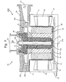
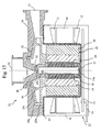
- Fig. 2 is a sectional view (a longitudinal sectional view) of the pump 110.
- Fig. 3 is a view for describing an impeller 25.
- (a) is a schematic view of blades 25c of the impeller 25 as seen in the X direction (a suction direction of a liquid) of Fig. 2 .
- (b) shows the section A-A of (a) of Fig. 3 .
- Fig. 4 is a view showing a configuration example of a shaft hole 24a of an upper casing as seen in the X direction of Fig. 2 .
- the shaft hole 24a of the upper casing has a shape with four legs (24a-1), but this is an example.
- the shaft hole 24a may be configured in any shape that allows the shaft 27 to be fitted therein and that does not offer great resistance to the liquid to be drawn in.
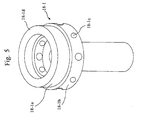
- Fig. 5 is a perspective view of a bearing (18-1) of the pump 110.
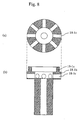
- Fig. 6 shows a plan view (as seen in the X direction) and a front view of the bearing (18-1).
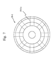
- Fig. 7 is a view showing the plan view of Fig. 6 ((a) of Fig. 6 ) with through holes (18-1c) indicated by dashed lines.
- Fig. 8 shows the section B-B and the section C-C of (b) of Fig. 6 .
- the heat pump apparatus 100 is configured with a compressor 1 that compresses a refrigerant, heat exchangers 3a and 3b, and so on.
- the heat pump apparatus 100 includes a refrigerant circuit 5 through which a refrigerant 9 flows.
- the heat exchanger 3a is a radiator, and the heat exchanger 3a, a heat utilization device 101 that utilizes hot water heated by the heat exchanger 3a, and the pump 110 are connected with pipes, thereby forming a liquid circuit 4 through which a liquid 8 flows.
- the heat utilization device 101 include a tank for storing a liquid and an external heating element such as a floor heating panel.
- the pump 110 is configured such that the bearing (18-1) rotates with a rotor part 21.
- the pump 110 includes a stator part 17, the rotor part 21, a pump part 26, and the shaft 27.
- the shaft 27 is fixed (non-rotatable).
- the rotor part 21 rotates around the shaft 27.
- the rotor part 21 is configured with the bearing (18-1), a coupling member 19, and a magnet part 20.
- the bearing (18-1) is positioned at a center portion of the rotor part 21.
- the coupling member 19 made of resin is positioned around the bearing (18-1).
- the magnet part 20 coupled with the bearing (18-1) by the coupling member 19 is positioned around the coupling member 19.
- the pump part 26 includes an upper casing 24 having a suction inlet 22 and a discharge outlet 23 and the impeller 25.
- the liquid circuit 4 is connected with the suction inlet 22 and the discharge outlet 23.
- the rotor part 21 is housed in a hollow portion of the approximately pot-shaped lower casing 15.
- a shaft hole 15a into which the shaft 27 is fitted is formed at a center portion of the hollow portion of the lower casing 15.
- the shaft 27 is inserted into the shaft hole 15a in a non-rotatable manner. To achieve this, the shaft 27 to be inserted into the shaft hole 15a has a notched portion in its circular shape.
- the bearing (18-1) of the rotor part 21 is inserted over the shaft 27 fixed to the lower casing 15.
- a thrust washer 28 is further placed on the bearing (18-1) such that an end face (18-1d) of the bearing (18-1) comes into contact with the thrust washer 28, thereby forming a thrust bearing.
- the end portion of the shaft 27 facing the pump part 26, which protrudes from the thrust washer 28 is inserted into the shaft hole 24a of the upper casing, so as to form the pump part 26 enclosed in the upper and lower casings.
- the rotor part 21 to which the impeller 25 is fixed is placed around the shaft 27 in a freely rotatable manner.
- the pump 110 is a canned pump in which the liquid flowing through the pump 110 comes into contact with the rotor part 21 of the brushless DC motor.
- the bearing (18-1) is configured to pass through a center portion (a center area 25d) of the impeller 25 and protrude from an upper blade plate 25a toward the suction inlet 22.
- the bearing (18-1) is formed such that the outer radius of this protruding portion, namely a cylinder portion (18-1a), is equivalent to or slightly larger than the inside radius of the suction inlet 22 and larger than a shaft support portion.
- the thrust washer 28 is placed in slidable contact with the upper end face (18-1d) of the cylinder portion (18-1a), thereby forming the thrust bearing.
- the thrust washer 28 is made to contact the end face (18-1d) of the bearing (18-1) so as to be non-rotatable in the rotational direction relative to the upper casing 24.
- a flow path (a guide portion) is provided in the bearing (18-1) in order to make the liquid flow from the suction inlet 22 through the impeller 25 to the discharge outlet 23 in a direction approximately perpendicular to the shaft.
- This flow path is formed, for example, by a plurality of the through holes (18-1c) placed at a longitudinal position corresponding to a longitudinal position of the impeller 25.
- the through holes (18-1c) provided in the bearing (18-1) form flow paths continuing from flow paths of the impeller 25. This makes it possible to extend an effective length of the blades 25c toward the inside radius of the suction inlet 22. It is also possible to reduce a pressure difference between the upper blade plate 25a and the lower blade plate 25b, so that thrust force applied to the thrust bearing can be reduced and friction loss can be reduced. Conventionally, a shaft support portion 35 of the upper casing 24 is fitted into the hollow portion of the center portion of the impeller 25, thereby making the effective length of the blades 25c shorter.
- the bearing (18-1) that rotates with the rotor part 21 has the through holes (18-1c) acting as the flow paths directed approximately perpendicularly to the shaft.
- These flow paths thus function in practically the same manner as the blades 25c, thereby providing the same effect as extending the blades 25c toward the inside radius (a shrouding effect).
- the pump 110 includes the suction inlet 22 through which the liquid is drawn in and the discharge outlet 23 through which the liquid drawn in is discharged.
- a suction direction X and a discharge direction Y of the liquid are approximately perpendicular to each other.
- the pump 110 includes the shaft 27, the impeller 25, and the bearing (18-1).
- the shaft 27 is positioned downstream of the suction inlet 22 such that a longitudinal direction of the shaft 27 is approximately the same as the suction direction X.
- the impeller 25 has the shape of a disk that rotates around the shaft 27. That is, as shown in Fig.
- the impeller 25 rotates around an axis of rotation 27a located in the shaft 27.
- the impeller 25 includes a plurality of the blades 25c formed radially in a radial direction from the center area 25d located at a center portion of the disk shape as seen in the suction direction X.
- the impeller 25 is positioned such that the longitudinal position of the plurality of the blades 25c is approximately the same as the longitudinal position of the discharge outlet 23, the longitudinal direction being defined in terms of the longitudinal direction of the shaft 27.
- the rotor part 21 coupled with the impeller 25 rotates around the shaft 27, thereby causing the liquid to be drawn in through the suction inlet 22 and discharged through the discharge outlet 23.
- the bearing (18-1) receives the shaft 27.
- the bearing (18-1) has the guide portion (flow paths) positioned in the center area 25d of the impeller 25.
- the guide portion is the through holes (18-1c).
- the through holes (18-1c) guide the liquid drawn in through the suction inlet 22 to the discharge outlet 23.
- the flow paths may have any sectional shape, and the area thereof may be larger at the outside radius than at the inside radius.
- the impeller 25 is configured with the upper blade plate 25a, a lower blade plate 25b, and the plurality of the blades 25c.
- the upper blade plate 25a forms an upper side of the disk-shaped impeller 25.
- the suction opening 36 ((a) of Fig. 3 ) is formed at the center portion of the upper blade plate 25a, the suction opening 36 being a circular opening through which the liquid drawn in through the suction inlet 22 is drawn in.
- the lower blade plate 25b forms a lower side of the disk shape, and is positioned to face the upper blade plate 25a.
- the plurality of the blades 25c may be formed between the upper blade plate 25a and the lower blade plate 25b.
- the blades 25c may be formed integrally with the upper blade plate 25a or the lower blade plate 25b.
- the bearing (18-1) includes the cylinder portion (18-1a) which is hollow and a thick cylinder portion (18-1b) (an example of the guide portion) which is hollow, thick-walled, and formed continuously with (under) the cylinder portion (18-1a).
- the cylinder portion (18-1a) fits into the suction opening 36 of the upper blade plate 25a, and the side wall of the cylinder portion (18-1a) is in close contact with the edge of the suction opening 36 (the region 37 in Fig. 2 ).
- welding or the like may be used, for example.
- the thick cylinder portion ( 18-1b) has a thick wall thicker than a wall of the cylinder portion (18-1a).
- the plurality of the through holes (18-1c) are formed in this thick wall so as to be directed approximately perpendicularly to the shaft 27.
- the side wall of the cylinder portion (18-1a) is in slidable contact with the edge of the suction opening 36 (the region 37 in Fig. 2 ), so that backflow can be prevented.
- the pump 110 includes the upper casing 24 in which the suction inlet 22 is formed, and the thrust washer 28 supported by the upper casing 24 so as to be non-rotatable relative to the shaft 27.
- the bearing (18-1) constitutes the thrust bearing by the upper end face (18-1d) of the cylinder portion (18-1a), the thrust washer 28, and a support portion 24b of the upper casing supporting the thrust washer 28.
- the bearing (18-1) of the first embodiment is a single-component bearing that functions both in radial and thrust directions, and thus also has the effect of being more dimensionally accurate compared to when the radial and thrust directions are supported by separate bearings.
- the configuration of the pump 110 of the first embodiment described above reduces the friction loss of the thrust bearing, extends the effective length of the blades toward the inside radius of the suction inlet 22, and prevents the backflow of the liquid to the suction inlet 22, thereby making it possible to provide a highly efficient and long-life pump and heat pump apparatus.
- a second embodiment differs from the first embodiment in the configuration of the bearing.
- a bearing (18-2) of the second embodiment is configured such that flow paths are formed by a plurality of blades (18c-2) in contrast to the plurality of the through holes of the bearing (18-1) of the first embodiment.
- the second embodiment is the same as the first embodiment.
- the bearing (18-2) rotates with the rotor part 21.
- Fig. 9 is a sectional view of the pump 120 of the second embodiment.
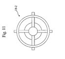
- Fig. 10 is a perspective view of the bearing (18-2).
- the bearing (18-2) includes the plurality of the blades (18c-2) as the guide portion for guiding the liquid drawn in through the suction inlet 22 to the discharge outlet 23.
- Fig. 11 is a plan view of the bearing (18-2) (as seen in the X direction).
- the bearing (18-2) includes the plurality of the blades (18c-2) forming flow paths for passing the liquid from the suction inlet 22 through the impeller 25 to the discharge outlet 23 in a direction approximately perpendicular to the shaft.
- the blades (18c-2) may be formed to correspond with the blades 25c of the impeller 25. That is, when the blades 25c are formed in a circular arc or an involute curve, the blades (18c-2) may be formed based on the same pattern rule (formed to have the same radius of curvature or involute curve).
- the number of the blades (18c-2) provided in the bearing (18-2) may be the same as or larger or smaller than the number of the blades 25c of the impeller 25. In other respects, the configuration is the same as that of the first embodiment.
- a pump 130 of a third embodiment will be described.
- the pump 130 of the third embodiment will be described wherein the bearing (18-2) of the second embodiment is divided into an upper part and a lower part.
- the shaft 27 and an upper bearing (18-3a) rotate with the rotor part 21.
- the impeller 25 is fixed to the rotor part 21.
- the impeller 25 rotates around the axis of rotation 27a located in the shaft 27.
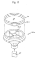
- Fig. 12 is a sectional view of the pump 130 of the third embodiment.
- the bearing is divided into two parts, namely the upper bearing (18-3a) and a lower bearing (18-3b).
- the upper bearing (18-3a) receives one end portion of the shaft 27 at a side facing the suction inlet 22, and includes a plurality ofblades (18c-3) ( Fig. 13 ) as the guide portion.
- the lower bearing (18-3b) receives the other end portion of the shaft 27 at the opposite side from the suction inlet 22.
- Fig. 13 is a perspective view of the upper bearing (18-3a).
- the upper bearing (18-3a) has the plurality of the blades (18c-3) as the guide portion.
- Fig. 14 shows a front view (as seen in the X direction of Fig. 1 ) and a sectional view taken on the line D-D.
- the magnet part 20 and the shaft 27 are coupled by the coupling member 19.
- the coupling member 19 also serves as the lower blade plate 25b.
- These (the magnet part 20, the shaft 27, and the coupling member 19) are fixedly coupled as one unit in both rotational and axial directions.
- the blades 25c and the upper blade plate 25a are fixedly coupled to the lower blade plate 25b by welding or the like, so as to form one unit.
- the magnet part 20, the coupling member 19, the shaft 27, the upper bearing (18-3a), and so on constitute the rotor.
- the lower bearing (18-3b) is fitted into the shaft hole 15a of the lower casing 15 so as to be non-rotatable in the rotational direction.
- a lower end portion of the shaft 27 coupled with the rotor part 21 is inserted into the lower bearing (18-3b) in a freely rotatable manner.
- the upper bearing (18-3a) is inserted over an upper end portion of the shaft 27 so as to be non-rotatable in the rotational direction relative to the shaft 27. That is, the upper bearing (18-3a) and the rotor part 21 rotate in unison.
- an upper portion of the upper bearing (18-3a) is shaped like an inverted triangular pyramid, and is in slidable contact, in both thrust and radial directions, with the thrust washer 28 outside (under) the radius of the suction inlet 22.
- Fig. 13 shows how the thrust washer 28 is attached to the upper bearing (18-3a).
- the thrust washer 28 is attached to the suction inlet 22 of the upper casing 24 so as to be non-rotatable in the rotational direction.
- the thrust washer 28 may be made non-rotatable in the rotational direction, for example as shown in Fig.
- the upper portion of the upper bearing (18-3a) includes the blades (18c-3), having a cross-sectional shape (the same as the shape of the blades (18c-3) shown in (a) of Fig. 14 ) closely resembling (a shape approximately the same as) the shape of the blades 25c of the impeller 25.
- the number of the blades and the phase thereof are also made to closely resemble (to be approximately the same as) those of the blades 25c, thereby forming flow paths by the blades (18c-3) (the guide portion).
- the configuration is the same as that of the first embodiment.
- the configuration of the third embodiment can also produce the same effect as the first embodiment.
- the pumps 110 to 130 described in the first to third embodiments have been shown, by way of example, as pumps used for conveying and circulating the liquid in the heat pump apparatus 100, but may also be adaptable to a household pump and so on.
Landscapes
- Engineering & Computer Science (AREA)
- Mechanical Engineering (AREA)
- General Engineering & Computer Science (AREA)
- Physics & Mathematics (AREA)
- Fluid Mechanics (AREA)
- Structures Of Non-Positive Displacement Pumps (AREA)
- Steam Or Hot-Water Central Heating Systems (AREA)
Applications Claiming Priority (1)
| Application Number | Priority Date | Filing Date | Title |
|---|---|---|---|
| JP2010135156A JP5465098B2 (ja) | 2010-06-14 | 2010-06-14 | ポンプ及びヒートポンプ装置 |
Publications (3)
| Publication Number | Publication Date |
|---|---|
| EP2397697A2 true EP2397697A2 (de) | 2011-12-21 |
| EP2397697A3 EP2397697A3 (de) | 2013-05-29 |
| EP2397697B1 EP2397697B1 (de) | 2019-09-04 |
Family
ID=44508563
Family Applications (1)
| Application Number | Title | Priority Date | Filing Date |
|---|---|---|---|
| EP11003499.8A Active EP2397697B1 (de) | 2010-06-14 | 2011-04-28 | Pumpe und wärmepumpenvorrichtung |
Country Status (4)
| Country | Link |
|---|---|
| US (1) | US8753068B2 (de) |
| EP (1) | EP2397697B1 (de) |
| JP (1) | JP5465098B2 (de) |
| CN (1) | CN102278313B (de) |
Cited By (4)
| Publication number | Priority date | Publication date | Assignee | Title |
|---|---|---|---|---|
| GB2488219A (en) * | 2011-02-21 | 2012-08-22 | Mitsubishi Electric Corp | Pump with inlet flow through rotating bearing |
| CN102852860A (zh) * | 2011-12-29 | 2013-01-02 | 江苏大学 | 一种可以减小离心泵进口回流的端盖 |
| CN104006001A (zh) * | 2014-05-29 | 2014-08-27 | 安徽银龙泵阀股份有限公司 | 一种带加热丝的泵芯 |
| WO2014137206A1 (en) * | 2013-03-07 | 2014-09-12 | Chaushevski Nikola | Rotational chamber pump |
Families Citing this family (13)
| Publication number | Priority date | Publication date | Assignee | Title |
|---|---|---|---|---|
| JP6129478B2 (ja) * | 2012-03-27 | 2017-05-17 | 日本電産サンキョー株式会社 | ポンプ装置およびポンプ装置の製造方法 |
| CN102691672A (zh) * | 2012-06-13 | 2012-09-26 | 哈尔滨大鑫新能源科技开发有限公司 | 一种增压减压平衡水泵 |
| DE102012223459A1 (de) * | 2012-12-17 | 2014-06-18 | Continental Automotive Gmbh | Kraftstoffpumpe |
| US10302088B2 (en) | 2013-06-20 | 2019-05-28 | Luraco, Inc. | Pump having a contactless, fluid sensor for dispensing a fluid to a setting |
| US9926933B2 (en) | 2013-06-20 | 2018-03-27 | Luraco, Inc. | Bearing and shaft assembly for jet assemblies |
| DE102013107986A1 (de) * | 2013-07-25 | 2015-01-29 | Xylem Ip Holdings Llc | Umwälzpumpe |
| CN104728122B (zh) * | 2013-12-23 | 2017-12-08 | 珠海格力节能环保制冷技术研究中心有限公司 | 屏蔽泵及其泵体入口结构 |
| US11698079B2 (en) | 2017-09-09 | 2023-07-11 | Luraco, Inc. | Fluid sealing member and fluid pump and motor having fluid sealing member |
| US10278894B1 (en) | 2018-02-05 | 2019-05-07 | Luraco, Inc. | Jet assembly having a friction-reducing member |
| DE102018211541A1 (de) * | 2018-07-11 | 2020-01-16 | Magna Powertrain Bad Homburg GmbH | Wasserpumpe |
| JP7299757B2 (ja) * | 2019-05-28 | 2023-06-28 | 株式会社ミクニ | インペラ及び遠心ポンプ |
| CN215109532U (zh) * | 2021-07-13 | 2021-12-10 | 盾安汽车热管理科技有限公司 | 电子水泵 |
| KR20250138426A (ko) * | 2024-03-13 | 2025-09-22 | 주식회사 코아비스 | 전동식 워터 펌프 |
Citations (1)
| Publication number | Priority date | Publication date | Assignee | Title |
|---|---|---|---|---|
| JP2008215738A (ja) | 2007-03-06 | 2008-09-18 | Mitsubishi Electric Corp | 給湯装置 |
Family Cites Families (22)
| Publication number | Priority date | Publication date | Assignee | Title |
|---|---|---|---|---|
| GB1204165A (en) * | 1967-08-19 | 1970-09-03 | Loewe Pumpenfabrik G M B H | Improvements in or relating to motor-driven impeller pumps |
| GB1496035A (en) | 1974-07-18 | 1977-12-21 | Iwaki Co Ltd | Magnetically driven centrifugal pump |
| JPH0633799B2 (ja) * | 1985-08-29 | 1994-05-02 | 株式会社日立製作所 | 遠心送風機 |
| JPH0379000U (de) * | 1989-12-06 | 1991-08-12 | ||
| JPH03237291A (ja) * | 1990-02-14 | 1991-10-23 | World Chem:Kk | マグネットポンプ |
| JPH07217600A (ja) * | 1994-01-28 | 1995-08-15 | Sankyo Seiki Mfg Co Ltd | ポンプ装置 |
| JP3718920B2 (ja) * | 1996-10-03 | 2005-11-24 | 松下電器産業株式会社 | 遠心ポンプ |
| US6135728A (en) * | 1998-10-29 | 2000-10-24 | Innovative Mag-Drive, L.L.C. | Centrifugal pump having an axial thrust balancing system |
| US6443710B1 (en) * | 1999-08-10 | 2002-09-03 | Iwaki Co., Ltd. | Magnetic pump |
| JP3475174B2 (ja) * | 2000-02-10 | 2003-12-08 | 東芝テック株式会社 | 電動ポンプ |
| US6439845B1 (en) * | 2000-03-23 | 2002-08-27 | Kidney Replacement Services, P.C. | Blood pump |
| JP3644491B2 (ja) * | 2000-09-11 | 2005-04-27 | 株式会社ジェイ・エム・エス | ターボ式血液ポンプ |
| JP2004183564A (ja) * | 2002-12-03 | 2004-07-02 | Calsonic Kansei Corp | ポンプ構造 |
| JP4381010B2 (ja) * | 2003-03-13 | 2009-12-09 | トーステ株式会社 | 渦巻ポンプ |
| JP2006200427A (ja) | 2005-01-20 | 2006-08-03 | Matsushita Electric Ind Co Ltd | ポンプ |
| US20060245955A1 (en) | 2005-04-18 | 2006-11-02 | Kiyotaka Horiuchi | Canned pump |
| DE102006027319B4 (de) * | 2006-06-13 | 2014-05-22 | Wilo Ag | Kreiselmotorpumpe mit drehrichtungsbestimmtem Anlauf |
| KR101115362B1 (ko) | 2006-12-07 | 2012-02-15 | 파나소닉 전공 주식회사 | 원심 펌프 |
| JP2008151074A (ja) * | 2006-12-19 | 2008-07-03 | Matsushita Electric Works Ltd | ポンプ |
| JP2008240655A (ja) | 2007-03-27 | 2008-10-09 | Matsushita Electric Works Ltd | ポンプの羽根車構造 |
| US20090062020A1 (en) | 2007-08-30 | 2009-03-05 | Edwards Stanley W | Multi-ribbed keyless coupling |
| JP2010007642A (ja) * | 2008-06-30 | 2010-01-14 | Nidec Sankyo Corp | ポンプ装置 |
-
2010
- 2010-06-14 JP JP2010135156A patent/JP5465098B2/ja not_active Expired - Fee Related
-
2011
- 2011-04-28 EP EP11003499.8A patent/EP2397697B1/de active Active
- 2011-04-28 US US13/096,419 patent/US8753068B2/en not_active Expired - Fee Related
- 2011-04-29 CN CN201110110141.5A patent/CN102278313B/zh not_active Expired - Fee Related
Patent Citations (1)
| Publication number | Priority date | Publication date | Assignee | Title |
|---|---|---|---|---|
| JP2008215738A (ja) | 2007-03-06 | 2008-09-18 | Mitsubishi Electric Corp | 給湯装置 |
Cited By (6)
| Publication number | Priority date | Publication date | Assignee | Title |
|---|---|---|---|---|
| GB2488219A (en) * | 2011-02-21 | 2012-08-22 | Mitsubishi Electric Corp | Pump with inlet flow through rotating bearing |
| GB2488219B (en) * | 2011-02-21 | 2013-01-02 | Mitsubishi Electric Corp | Pump and heat pump apparatus |
| CN102852860A (zh) * | 2011-12-29 | 2013-01-02 | 江苏大学 | 一种可以减小离心泵进口回流的端盖 |
| WO2014137206A1 (en) * | 2013-03-07 | 2014-09-12 | Chaushevski Nikola | Rotational chamber pump |
| CN104006001A (zh) * | 2014-05-29 | 2014-08-27 | 安徽银龙泵阀股份有限公司 | 一种带加热丝的泵芯 |
| CN104006001B (zh) * | 2014-05-29 | 2016-04-27 | 安徽银龙泵阀股份有限公司 | 一种带加热丝的泵芯 |
Also Published As
| Publication number | Publication date |
|---|---|
| JP5465098B2 (ja) | 2014-04-09 |
| CN102278313A (zh) | 2011-12-14 |
| US8753068B2 (en) | 2014-06-17 |
| JP2012002075A (ja) | 2012-01-05 |
| US20110305562A1 (en) | 2011-12-15 |
| EP2397697A3 (de) | 2013-05-29 |
| CN102278313B (zh) | 2014-12-17 |
| EP2397697B1 (de) | 2019-09-04 |
Similar Documents
| Publication | Publication Date | Title |
|---|---|---|
| US8753068B2 (en) | Pump and heat pump apparatus | |
| CN114733064B (zh) | 血泵 | |
| KR102365863B1 (ko) | 워터 펌프 | |
| CN210196043U (zh) | 水泵 | |
| CN211266684U (zh) | 一种端板设有叶轮的永磁电动机及使用该电动机的电动车 | |
| JP4931980B2 (ja) | 水循環ポンプ及びヒートポンプ装置 | |
| GB2488219A (en) | Pump with inlet flow through rotating bearing | |
| CN108626128B (zh) | 循环水泵 | |
| KR20160118612A (ko) | 전동식 워터 펌프 | |
| JP6381451B2 (ja) | 遠心ポンプ | |
| JP2014025472A (ja) | 液体循環装置 | |
| JP2022189307A (ja) | 冷却ファン、電動機組立体 | |
| WO2019116717A1 (ja) | 排水ポンプ用モータおよびその製造方法、ならびにそのモータを有する排水ポンプ | |
| JP6128525B2 (ja) | 渦流ファン | |
| CN109751248B (zh) | 一种汽车电子水泵 | |
| KR20230073969A (ko) | 워터 펌프용 임펠러 | |
| KR20260046884A (ko) | 워터 펌프 | |
| JP2018112190A (ja) | 直列式軸流ファン | |
| KR102817360B1 (ko) | 워터 펌프 | |
| JP2014118949A (ja) | 自吸式遠心ポンプ | |
| JP4168519B2 (ja) | 外部駆動形ラインポンプ | |
| JP4158269B2 (ja) | 外部駆動形ラインポンプ | |
| JP7416161B2 (ja) | 直列式軸流ファン | |
| JP6357766B2 (ja) | 液体ポンプ | |
| EP4685355A1 (de) | Wasserpumpe |
Legal Events
| Date | Code | Title | Description |
|---|---|---|---|
| AK | Designated contracting states |
Kind code of ref document: A2 Designated state(s): AL AT BE BG CH CY CZ DE DK EE ES FI FR GB GR HR HU IE IS IT LI LT LU LV MC MK MT NL NO PL PT RO RS SE SI SK SM TR |
|
| AX | Request for extension of the european patent |
Extension state: BA ME |
|
| PUAI | Public reference made under article 153(3) epc to a published international application that has entered the european phase |
Free format text: ORIGINAL CODE: 0009012 |
|
| PUAL | Search report despatched |
Free format text: ORIGINAL CODE: 0009013 |
|
| AK | Designated contracting states |
Kind code of ref document: A3 Designated state(s): AL AT BE BG CH CY CZ DE DK EE ES FI FR GB GR HR HU IE IS IT LI LT LU LV MC MK MT NL NO PL PT RO RS SE SI SK SM TR |
|
| AX | Request for extension of the european patent |
Extension state: BA ME |
|
| RIC1 | Information provided on ipc code assigned before grant |
Ipc: F04D 13/06 20060101AFI20130425BHEP Ipc: F04D 29/047 20060101ALI20130425BHEP |
|
| 17P | Request for examination filed |
Effective date: 20131014 |
|
| RBV | Designated contracting states (corrected) |
Designated state(s): AL AT BE BG CH CY CZ DE DK EE ES FI FR GB GR HR HU IE IS IT LI LT LU LV MC MK MT NL NO PL PT RO RS SE SI SK SM TR |
|
| GRAP | Despatch of communication of intention to grant a patent |
Free format text: ORIGINAL CODE: EPIDOSNIGR1 |
|
| STAA | Information on the status of an ep patent application or granted ep patent |
Free format text: STATUS: GRANT OF PATENT IS INTENDED |
|
| INTG | Intention to grant announced |
Effective date: 20190416 |
|
| GRAS | Grant fee paid |
Free format text: ORIGINAL CODE: EPIDOSNIGR3 |
|
| GRAA | (expected) grant |
Free format text: ORIGINAL CODE: 0009210 |
|
| STAA | Information on the status of an ep patent application or granted ep patent |
Free format text: STATUS: THE PATENT HAS BEEN GRANTED |
|
| AK | Designated contracting states |
Kind code of ref document: B1 Designated state(s): AL AT BE BG CH CY CZ DE DK EE ES FI FR GB GR HR HU IE IS IT LI LT LU LV MC MK MT NL NO PL PT RO RS SE SI SK SM TR |
|
| REG | Reference to a national code |
Ref country code: GB Ref legal event code: FG4D |
|
| REG | Reference to a national code |
Ref country code: CH Ref legal event code: EP |
|
| REG | Reference to a national code |
Ref country code: AT Ref legal event code: REF Ref document number: 1175720 Country of ref document: AT Kind code of ref document: T Effective date: 20190915 |
|
| REG | Reference to a national code |
Ref country code: DE Ref legal event code: R096 Ref document number: 602011061735 Country of ref document: DE |
|
| REG | Reference to a national code |
Ref country code: IE Ref legal event code: FG4D |
|
| REG | Reference to a national code |
Ref country code: NL Ref legal event code: MP Effective date: 20190904 |
|
| REG | Reference to a national code |
Ref country code: LT Ref legal event code: MG4D |
|
| PG25 | Lapsed in a contracting state [announced via postgrant information from national office to epo] |
Ref country code: FI Free format text: LAPSE BECAUSE OF FAILURE TO SUBMIT A TRANSLATION OF THE DESCRIPTION OR TO PAY THE FEE WITHIN THE PRESCRIBED TIME-LIMIT Effective date: 20190904 Ref country code: SE Free format text: LAPSE BECAUSE OF FAILURE TO SUBMIT A TRANSLATION OF THE DESCRIPTION OR TO PAY THE FEE WITHIN THE PRESCRIBED TIME-LIMIT Effective date: 20190904 Ref country code: LT Free format text: LAPSE BECAUSE OF FAILURE TO SUBMIT A TRANSLATION OF THE DESCRIPTION OR TO PAY THE FEE WITHIN THE PRESCRIBED TIME-LIMIT Effective date: 20190904 Ref country code: HR Free format text: LAPSE BECAUSE OF FAILURE TO SUBMIT A TRANSLATION OF THE DESCRIPTION OR TO PAY THE FEE WITHIN THE PRESCRIBED TIME-LIMIT Effective date: 20190904 Ref country code: NO Free format text: LAPSE BECAUSE OF FAILURE TO SUBMIT A TRANSLATION OF THE DESCRIPTION OR TO PAY THE FEE WITHIN THE PRESCRIBED TIME-LIMIT Effective date: 20191204 Ref country code: BG Free format text: LAPSE BECAUSE OF FAILURE TO SUBMIT A TRANSLATION OF THE DESCRIPTION OR TO PAY THE FEE WITHIN THE PRESCRIBED TIME-LIMIT Effective date: 20191204 |
|
| PG25 | Lapsed in a contracting state [announced via postgrant information from national office to epo] |
Ref country code: AL Free format text: LAPSE BECAUSE OF FAILURE TO SUBMIT A TRANSLATION OF THE DESCRIPTION OR TO PAY THE FEE WITHIN THE PRESCRIBED TIME-LIMIT Effective date: 20190904 Ref country code: ES Free format text: LAPSE BECAUSE OF FAILURE TO SUBMIT A TRANSLATION OF THE DESCRIPTION OR TO PAY THE FEE WITHIN THE PRESCRIBED TIME-LIMIT Effective date: 20190904 Ref country code: RS Free format text: LAPSE BECAUSE OF FAILURE TO SUBMIT A TRANSLATION OF THE DESCRIPTION OR TO PAY THE FEE WITHIN THE PRESCRIBED TIME-LIMIT Effective date: 20190904 Ref country code: LV Free format text: LAPSE BECAUSE OF FAILURE TO SUBMIT A TRANSLATION OF THE DESCRIPTION OR TO PAY THE FEE WITHIN THE PRESCRIBED TIME-LIMIT Effective date: 20190904 Ref country code: GR Free format text: LAPSE BECAUSE OF FAILURE TO SUBMIT A TRANSLATION OF THE DESCRIPTION OR TO PAY THE FEE WITHIN THE PRESCRIBED TIME-LIMIT Effective date: 20191205 |
|
| REG | Reference to a national code |
Ref country code: AT Ref legal event code: MK05 Ref document number: 1175720 Country of ref document: AT Kind code of ref document: T Effective date: 20190904 |
|
| PG25 | Lapsed in a contracting state [announced via postgrant information from national office to epo] |
Ref country code: RO Free format text: LAPSE BECAUSE OF FAILURE TO SUBMIT A TRANSLATION OF THE DESCRIPTION OR TO PAY THE FEE WITHIN THE PRESCRIBED TIME-LIMIT Effective date: 20190904 Ref country code: IT Free format text: LAPSE BECAUSE OF FAILURE TO SUBMIT A TRANSLATION OF THE DESCRIPTION OR TO PAY THE FEE WITHIN THE PRESCRIBED TIME-LIMIT Effective date: 20190904 Ref country code: PT Free format text: LAPSE BECAUSE OF FAILURE TO SUBMIT A TRANSLATION OF THE DESCRIPTION OR TO PAY THE FEE WITHIN THE PRESCRIBED TIME-LIMIT Effective date: 20200106 Ref country code: AT Free format text: LAPSE BECAUSE OF FAILURE TO SUBMIT A TRANSLATION OF THE DESCRIPTION OR TO PAY THE FEE WITHIN THE PRESCRIBED TIME-LIMIT Effective date: 20190904 Ref country code: NL Free format text: LAPSE BECAUSE OF FAILURE TO SUBMIT A TRANSLATION OF THE DESCRIPTION OR TO PAY THE FEE WITHIN THE PRESCRIBED TIME-LIMIT Effective date: 20190904 Ref country code: PL Free format text: LAPSE BECAUSE OF FAILURE TO SUBMIT A TRANSLATION OF THE DESCRIPTION OR TO PAY THE FEE WITHIN THE PRESCRIBED TIME-LIMIT Effective date: 20190904 Ref country code: EE Free format text: LAPSE BECAUSE OF FAILURE TO SUBMIT A TRANSLATION OF THE DESCRIPTION OR TO PAY THE FEE WITHIN THE PRESCRIBED TIME-LIMIT Effective date: 20190904 |
|
| PG25 | Lapsed in a contracting state [announced via postgrant information from national office to epo] |
Ref country code: CZ Free format text: LAPSE BECAUSE OF FAILURE TO SUBMIT A TRANSLATION OF THE DESCRIPTION OR TO PAY THE FEE WITHIN THE PRESCRIBED TIME-LIMIT Effective date: 20190904 Ref country code: IS Free format text: LAPSE BECAUSE OF FAILURE TO SUBMIT A TRANSLATION OF THE DESCRIPTION OR TO PAY THE FEE WITHIN THE PRESCRIBED TIME-LIMIT Effective date: 20200224 Ref country code: SM Free format text: LAPSE BECAUSE OF FAILURE TO SUBMIT A TRANSLATION OF THE DESCRIPTION OR TO PAY THE FEE WITHIN THE PRESCRIBED TIME-LIMIT Effective date: 20190904 Ref country code: SK Free format text: LAPSE BECAUSE OF FAILURE TO SUBMIT A TRANSLATION OF THE DESCRIPTION OR TO PAY THE FEE WITHIN THE PRESCRIBED TIME-LIMIT Effective date: 20190904 |
|
| REG | Reference to a national code |
Ref country code: DE Ref legal event code: R097 Ref document number: 602011061735 Country of ref document: DE |
|
| PLBE | No opposition filed within time limit |
Free format text: ORIGINAL CODE: 0009261 |
|
| STAA | Information on the status of an ep patent application or granted ep patent |
Free format text: STATUS: NO OPPOSITION FILED WITHIN TIME LIMIT |
|
| PG2D | Information on lapse in contracting state deleted |
Ref country code: IS |
|
| PG25 | Lapsed in a contracting state [announced via postgrant information from national office to epo] |
Ref country code: DK Free format text: LAPSE BECAUSE OF FAILURE TO SUBMIT A TRANSLATION OF THE DESCRIPTION OR TO PAY THE FEE WITHIN THE PRESCRIBED TIME-LIMIT Effective date: 20190904 Ref country code: IS Free format text: LAPSE BECAUSE OF FAILURE TO SUBMIT A TRANSLATION OF THE DESCRIPTION OR TO PAY THE FEE WITHIN THE PRESCRIBED TIME-LIMIT Effective date: 20200105 |
|
| 26N | No opposition filed |
Effective date: 20200605 |
|
| PG25 | Lapsed in a contracting state [announced via postgrant information from national office to epo] |
Ref country code: SI Free format text: LAPSE BECAUSE OF FAILURE TO SUBMIT A TRANSLATION OF THE DESCRIPTION OR TO PAY THE FEE WITHIN THE PRESCRIBED TIME-LIMIT Effective date: 20190904 |
|
| PG25 | Lapsed in a contracting state [announced via postgrant information from national office to epo] |
Ref country code: MC Free format text: LAPSE BECAUSE OF FAILURE TO SUBMIT A TRANSLATION OF THE DESCRIPTION OR TO PAY THE FEE WITHIN THE PRESCRIBED TIME-LIMIT Effective date: 20190904 |
|
| REG | Reference to a national code |
Ref country code: CH Ref legal event code: PL |
|
| PG25 | Lapsed in a contracting state [announced via postgrant information from national office to epo] |
Ref country code: LI Free format text: LAPSE BECAUSE OF NON-PAYMENT OF DUE FEES Effective date: 20200430 Ref country code: LU Free format text: LAPSE BECAUSE OF NON-PAYMENT OF DUE FEES Effective date: 20200428 Ref country code: FR Free format text: LAPSE BECAUSE OF NON-PAYMENT OF DUE FEES Effective date: 20200430 Ref country code: CH Free format text: LAPSE BECAUSE OF NON-PAYMENT OF DUE FEES Effective date: 20200430 |
|
| REG | Reference to a national code |
Ref country code: BE Ref legal event code: MM Effective date: 20200430 |
|
| PG25 | Lapsed in a contracting state [announced via postgrant information from national office to epo] |
Ref country code: BE Free format text: LAPSE BECAUSE OF NON-PAYMENT OF DUE FEES Effective date: 20200430 |
|
| PG25 | Lapsed in a contracting state [announced via postgrant information from national office to epo] |
Ref country code: IE Free format text: LAPSE BECAUSE OF NON-PAYMENT OF DUE FEES Effective date: 20200428 |
|
| PG25 | Lapsed in a contracting state [announced via postgrant information from national office to epo] |
Ref country code: TR Free format text: LAPSE BECAUSE OF FAILURE TO SUBMIT A TRANSLATION OF THE DESCRIPTION OR TO PAY THE FEE WITHIN THE PRESCRIBED TIME-LIMIT Effective date: 20190904 Ref country code: MT Free format text: LAPSE BECAUSE OF FAILURE TO SUBMIT A TRANSLATION OF THE DESCRIPTION OR TO PAY THE FEE WITHIN THE PRESCRIBED TIME-LIMIT Effective date: 20190904 Ref country code: CY Free format text: LAPSE BECAUSE OF FAILURE TO SUBMIT A TRANSLATION OF THE DESCRIPTION OR TO PAY THE FEE WITHIN THE PRESCRIBED TIME-LIMIT Effective date: 20190904 |
|
| PG25 | Lapsed in a contracting state [announced via postgrant information from national office to epo] |
Ref country code: MK Free format text: LAPSE BECAUSE OF FAILURE TO SUBMIT A TRANSLATION OF THE DESCRIPTION OR TO PAY THE FEE WITHIN THE PRESCRIBED TIME-LIMIT Effective date: 20190904 |
|
| PGFP | Annual fee paid to national office [announced via postgrant information from national office to epo] |
Ref country code: GB Payment date: 20230309 Year of fee payment: 13 |
|
| P01 | Opt-out of the competence of the unified patent court (upc) registered |
Effective date: 20230512 |
|
| PGFP | Annual fee paid to national office [announced via postgrant information from national office to epo] |
Ref country code: DE Payment date: 20230228 Year of fee payment: 13 |
|
| REG | Reference to a national code |
Ref country code: DE Ref legal event code: R119 Ref document number: 602011061735 Country of ref document: DE |
|
| GBPC | Gb: european patent ceased through non-payment of renewal fee |
Effective date: 20240428 |
|
| PG25 | Lapsed in a contracting state [announced via postgrant information from national office to epo] |
Ref country code: DE Free format text: LAPSE BECAUSE OF NON-PAYMENT OF DUE FEES Effective date: 20241105 |
|
| PG25 | Lapsed in a contracting state [announced via postgrant information from national office to epo] |
Ref country code: GB Free format text: LAPSE BECAUSE OF NON-PAYMENT OF DUE FEES Effective date: 20240428 |
|
| PG25 | Lapsed in a contracting state [announced via postgrant information from national office to epo] |
Ref country code: GB Free format text: LAPSE BECAUSE OF NON-PAYMENT OF DUE FEES Effective date: 20240428 Ref country code: DE Free format text: LAPSE BECAUSE OF NON-PAYMENT OF DUE FEES Effective date: 20241105 |