EP2397108A2 - Dispositif pour traitement d'une valvule cardiaque défectueuse - Google Patents
Dispositif pour traitement d'une valvule cardiaque défectueuse Download PDFInfo
- Publication number
- EP2397108A2 EP2397108A2 EP11004546A EP11004546A EP2397108A2 EP 2397108 A2 EP2397108 A2 EP 2397108A2 EP 11004546 A EP11004546 A EP 11004546A EP 11004546 A EP11004546 A EP 11004546A EP 2397108 A2 EP2397108 A2 EP 2397108A2
- Authority
- EP
- European Patent Office
- Prior art keywords
- balloon
- catheter
- valve
- shaft
- distal end
- Prior art date
- Legal status (The legal status is an assumption and is not a legal conclusion. Google has not performed a legal analysis and makes no representation as to the accuracy of the status listed.)
- Granted
Links
- 210000003709 heart valve Anatomy 0.000 title claims abstract description 9
- 230000002950 deficient Effects 0.000 title claims abstract 3
- 210000005166 vasculature Anatomy 0.000 claims abstract description 51
- 230000007246 mechanism Effects 0.000 claims abstract description 34
- 238000002513 implantation Methods 0.000 claims abstract description 22
- 239000010410 layer Substances 0.000 description 34
- 239000000463 material Substances 0.000 description 20
- 239000002184 metal Substances 0.000 description 16
- 238000000034 method Methods 0.000 description 14
- 229920002614 Polyether block amide Polymers 0.000 description 12
- 210000001105 femoral artery Anatomy 0.000 description 12
- 239000012530 fluid Substances 0.000 description 12
- 238000007789 sealing Methods 0.000 description 12
- 210000002376 aorta thoracic Anatomy 0.000 description 9
- 210000001765 aortic valve Anatomy 0.000 description 8
- 238000003780 insertion Methods 0.000 description 8
- 230000037431 insertion Effects 0.000 description 8
- 238000004891 communication Methods 0.000 description 6
- 230000002829 reductive effect Effects 0.000 description 6
- 239000004677 Nylon Substances 0.000 description 5
- 210000000709 aorta Anatomy 0.000 description 5
- 208000014674 injury Diseases 0.000 description 5
- 229920001778 nylon Polymers 0.000 description 5
- 229910001220 stainless steel Inorganic materials 0.000 description 5
- 230000008733 trauma Effects 0.000 description 5
- 210000004204 blood vessel Anatomy 0.000 description 4
- 210000003090 iliac artery Anatomy 0.000 description 4
- 239000007943 implant Substances 0.000 description 4
- 239000010935 stainless steel Substances 0.000 description 4
- 230000002966 stenotic effect Effects 0.000 description 4
- 230000002792 vascular Effects 0.000 description 4
- 239000000853 adhesive Substances 0.000 description 3
- 230000001070 adhesive effect Effects 0.000 description 3
- 238000013459 approach Methods 0.000 description 3
- 210000001367 artery Anatomy 0.000 description 3
- 238000010276 construction Methods 0.000 description 3
- 230000007423 decrease Effects 0.000 description 3
- 230000004048 modification Effects 0.000 description 3
- 238000012986 modification Methods 0.000 description 3
- 229910001000 nickel titanium Inorganic materials 0.000 description 3
- HLXZNVUGXRDIFK-UHFFFAOYSA-N nickel titanium Chemical compound [Ti].[Ti].[Ti].[Ti].[Ti].[Ti].[Ti].[Ti].[Ti].[Ti].[Ti].[Ni].[Ni].[Ni].[Ni].[Ni].[Ni].[Ni].[Ni].[Ni].[Ni].[Ni].[Ni].[Ni].[Ni] HLXZNVUGXRDIFK-UHFFFAOYSA-N 0.000 description 3
- 230000036961 partial effect Effects 0.000 description 3
- 239000013047 polymeric layer Substances 0.000 description 3
- 230000000717 retained effect Effects 0.000 description 3
- 238000005452 bending Methods 0.000 description 2
- 230000008901 benefit Effects 0.000 description 2
- 210000003445 biliary tract Anatomy 0.000 description 2
- 239000000560 biocompatible material Substances 0.000 description 2
- 239000008280 blood Substances 0.000 description 2
- 210000004369 blood Anatomy 0.000 description 2
- 239000011248 coating agent Substances 0.000 description 2
- 238000000576 coating method Methods 0.000 description 2
- 230000000295 complement effect Effects 0.000 description 2
- 230000003247 decreasing effect Effects 0.000 description 2
- 210000005069 ears Anatomy 0.000 description 2
- 230000002124 endocrine Effects 0.000 description 2
- 210000003238 esophagus Anatomy 0.000 description 2
- 210000000936 intestine Anatomy 0.000 description 2
- 210000003101 oviduct Anatomy 0.000 description 2
- -1 peek Substances 0.000 description 2
- 238000001356 surgical procedure Methods 0.000 description 2
- 230000007704 transition Effects 0.000 description 2
- 210000003708 urethra Anatomy 0.000 description 2
- 210000003462 vein Anatomy 0.000 description 2
- JOYRKODLDBILNP-UHFFFAOYSA-N Ethyl urethane Chemical compound CCOC(N)=O JOYRKODLDBILNP-UHFFFAOYSA-N 0.000 description 1
- 239000004743 Polypropylene Substances 0.000 description 1
- 239000004809 Teflon Substances 0.000 description 1
- 229920006362 Teflon® Polymers 0.000 description 1
- 208000027418 Wounds and injury Diseases 0.000 description 1
- 210000000702 aorta abdominal Anatomy 0.000 description 1
- 210000004351 coronary vessel Anatomy 0.000 description 1
- 238000002788 crimping Methods 0.000 description 1
- 229920001971 elastomer Polymers 0.000 description 1
- 239000000806 elastomer Substances 0.000 description 1
- 238000002594 fluoroscopy Methods 0.000 description 1
- 239000002783 friction material Substances 0.000 description 1
- 230000002439 hemostatic effect Effects 0.000 description 1
- 210000005240 left ventricle Anatomy 0.000 description 1
- 230000000670 limiting effect Effects 0.000 description 1
- 239000003550 marker Substances 0.000 description 1
- 230000037361 pathway Effects 0.000 description 1
- 229920001195 polyisoprene Polymers 0.000 description 1
- 229920001155 polypropylene Polymers 0.000 description 1
- 229920001343 polytetrafluoroethylene Polymers 0.000 description 1
- 239000004810 polytetrafluoroethylene Substances 0.000 description 1
- 238000003825 pressing Methods 0.000 description 1
- 230000008569 process Effects 0.000 description 1
- 230000004044 response Effects 0.000 description 1
- 238000000926 separation method Methods 0.000 description 1
- 229910052710 silicon Inorganic materials 0.000 description 1
- 239000010703 silicon Substances 0.000 description 1
- 125000006850 spacer group Chemical group 0.000 description 1
- 229920002725 thermoplastic elastomer Polymers 0.000 description 1
- 230000000472 traumatic effect Effects 0.000 description 1
- XLYOFNOQVPJJNP-UHFFFAOYSA-N water Substances O XLYOFNOQVPJJNP-UHFFFAOYSA-N 0.000 description 1
- 238000003466 welding Methods 0.000 description 1
Images


Classifications
-
- A—HUMAN NECESSITIES
- A61—MEDICAL OR VETERINARY SCIENCE; HYGIENE
- A61F—FILTERS IMPLANTABLE INTO BLOOD VESSELS; PROSTHESES; DEVICES PROVIDING PATENCY TO, OR PREVENTING COLLAPSING OF, TUBULAR STRUCTURES OF THE BODY, e.g. STENTS; ORTHOPAEDIC, NURSING OR CONTRACEPTIVE DEVICES; FOMENTATION; TREATMENT OR PROTECTION OF EYES OR EARS; BANDAGES, DRESSINGS OR ABSORBENT PADS; FIRST-AID KITS
- A61F2/00—Filters implantable into blood vessels; Prostheses, i.e. artificial substitutes or replacements for parts of the body; Appliances for connecting them with the body; Devices providing patency to, or preventing collapsing of, tubular structures of the body, e.g. stents
- A61F2/02—Prostheses implantable into the body
- A61F2/24—Heart valves ; Vascular valves, e.g. venous valves; Heart implants, e.g. passive devices for improving the function of the native valve or the heart muscle; Transmyocardial revascularisation [TMR] devices; Valves implantable in the body
- A61F2/2427—Devices for manipulating or deploying heart valves during implantation
- A61F2/243—Deployment by mechanical expansion
- A61F2/2433—Deployment by mechanical expansion using balloon catheter
-
- A—HUMAN NECESSITIES
- A61—MEDICAL OR VETERINARY SCIENCE; HYGIENE
- A61F—FILTERS IMPLANTABLE INTO BLOOD VESSELS; PROSTHESES; DEVICES PROVIDING PATENCY TO, OR PREVENTING COLLAPSING OF, TUBULAR STRUCTURES OF THE BODY, e.g. STENTS; ORTHOPAEDIC, NURSING OR CONTRACEPTIVE DEVICES; FOMENTATION; TREATMENT OR PROTECTION OF EYES OR EARS; BANDAGES, DRESSINGS OR ABSORBENT PADS; FIRST-AID KITS
- A61F2/00—Filters implantable into blood vessels; Prostheses, i.e. artificial substitutes or replacements for parts of the body; Appliances for connecting them with the body; Devices providing patency to, or preventing collapsing of, tubular structures of the body, e.g. stents
- A61F2/02—Prostheses implantable into the body
- A61F2/24—Heart valves ; Vascular valves, e.g. venous valves; Heart implants, e.g. passive devices for improving the function of the native valve or the heart muscle; Transmyocardial revascularisation [TMR] devices; Valves implantable in the body
- A61F2/2427—Devices for manipulating or deploying heart valves during implantation
- A61F2/2436—Deployment by retracting a sheath
-
- A—HUMAN NECESSITIES
- A61—MEDICAL OR VETERINARY SCIENCE; HYGIENE
- A61M—DEVICES FOR INTRODUCING MEDIA INTO, OR ONTO, THE BODY; DEVICES FOR TRANSDUCING BODY MEDIA OR FOR TAKING MEDIA FROM THE BODY; DEVICES FOR PRODUCING OR ENDING SLEEP OR STUPOR
- A61M25/00—Catheters; Hollow probes
- A61M25/01—Introducing, guiding, advancing, emplacing or holding catheters
- A61M25/0105—Steering means as part of the catheter or advancing means; Markers for positioning
- A61M25/0133—Tip steering devices
- A61M25/0136—Handles therefor
-
- A—HUMAN NECESSITIES
- A61—MEDICAL OR VETERINARY SCIENCE; HYGIENE
- A61M—DEVICES FOR INTRODUCING MEDIA INTO, OR ONTO, THE BODY; DEVICES FOR TRANSDUCING BODY MEDIA OR FOR TAKING MEDIA FROM THE BODY; DEVICES FOR PRODUCING OR ENDING SLEEP OR STUPOR
- A61M25/00—Catheters; Hollow probes
- A61M25/01—Introducing, guiding, advancing, emplacing or holding catheters
- A61M25/06—Body-piercing guide needles or the like
- A61M25/0662—Guide tubes
-
- A—HUMAN NECESSITIES
- A61—MEDICAL OR VETERINARY SCIENCE; HYGIENE
- A61F—FILTERS IMPLANTABLE INTO BLOOD VESSELS; PROSTHESES; DEVICES PROVIDING PATENCY TO, OR PREVENTING COLLAPSING OF, TUBULAR STRUCTURES OF THE BODY, e.g. STENTS; ORTHOPAEDIC, NURSING OR CONTRACEPTIVE DEVICES; FOMENTATION; TREATMENT OR PROTECTION OF EYES OR EARS; BANDAGES, DRESSINGS OR ABSORBENT PADS; FIRST-AID KITS
- A61F2/00—Filters implantable into blood vessels; Prostheses, i.e. artificial substitutes or replacements for parts of the body; Appliances for connecting them with the body; Devices providing patency to, or preventing collapsing of, tubular structures of the body, e.g. stents
- A61F2/95—Instruments specially adapted for placement or removal of stents or stent-grafts
- A61F2/9517—Instruments specially adapted for placement or removal of stents or stent-grafts handle assemblies therefor
-
- A—HUMAN NECESSITIES
- A61—MEDICAL OR VETERINARY SCIENCE; HYGIENE
- A61F—FILTERS IMPLANTABLE INTO BLOOD VESSELS; PROSTHESES; DEVICES PROVIDING PATENCY TO, OR PREVENTING COLLAPSING OF, TUBULAR STRUCTURES OF THE BODY, e.g. STENTS; ORTHOPAEDIC, NURSING OR CONTRACEPTIVE DEVICES; FOMENTATION; TREATMENT OR PROTECTION OF EYES OR EARS; BANDAGES, DRESSINGS OR ABSORBENT PADS; FIRST-AID KITS
- A61F2/00—Filters implantable into blood vessels; Prostheses, i.e. artificial substitutes or replacements for parts of the body; Appliances for connecting them with the body; Devices providing patency to, or preventing collapsing of, tubular structures of the body, e.g. stents
- A61F2/95—Instruments specially adapted for placement or removal of stents or stent-grafts
- A61F2/958—Inflatable balloons for placing stents or stent-grafts
-
- A—HUMAN NECESSITIES
- A61—MEDICAL OR VETERINARY SCIENCE; HYGIENE
- A61M—DEVICES FOR INTRODUCING MEDIA INTO, OR ONTO, THE BODY; DEVICES FOR TRANSDUCING BODY MEDIA OR FOR TAKING MEDIA FROM THE BODY; DEVICES FOR PRODUCING OR ENDING SLEEP OR STUPOR
- A61M25/00—Catheters; Hollow probes
- A61M25/0043—Catheters; Hollow probes characterised by structural features
- A61M25/0045—Catheters; Hollow probes characterised by structural features multi-layered, e.g. coated
-
- A—HUMAN NECESSITIES
- A61—MEDICAL OR VETERINARY SCIENCE; HYGIENE
- A61M—DEVICES FOR INTRODUCING MEDIA INTO, OR ONTO, THE BODY; DEVICES FOR TRANSDUCING BODY MEDIA OR FOR TAKING MEDIA FROM THE BODY; DEVICES FOR PRODUCING OR ENDING SLEEP OR STUPOR
- A61M25/00—Catheters; Hollow probes
- A61M25/0043—Catheters; Hollow probes characterised by structural features
- A61M25/005—Catheters; Hollow probes characterised by structural features with embedded materials for reinforcement, e.g. wires, coils, braids
-
- A—HUMAN NECESSITIES
- A61—MEDICAL OR VETERINARY SCIENCE; HYGIENE
- A61M—DEVICES FOR INTRODUCING MEDIA INTO, OR ONTO, THE BODY; DEVICES FOR TRANSDUCING BODY MEDIA OR FOR TAKING MEDIA FROM THE BODY; DEVICES FOR PRODUCING OR ENDING SLEEP OR STUPOR
- A61M25/00—Catheters; Hollow probes
- A61M25/01—Introducing, guiding, advancing, emplacing or holding catheters
- A61M25/0105—Steering means as part of the catheter or advancing means; Markers for positioning
- A61M25/0133—Tip steering devices
- A61M25/0147—Tip steering devices with movable mechanical means, e.g. pull wires
-
- A—HUMAN NECESSITIES
- A61—MEDICAL OR VETERINARY SCIENCE; HYGIENE
- A61M—DEVICES FOR INTRODUCING MEDIA INTO, OR ONTO, THE BODY; DEVICES FOR TRANSDUCING BODY MEDIA OR FOR TAKING MEDIA FROM THE BODY; DEVICES FOR PRODUCING OR ENDING SLEEP OR STUPOR
- A61M39/00—Tubes, tube connectors, tube couplings, valves, access sites or the like, specially adapted for medical use
- A61M39/02—Access sites
- A61M39/06—Haemostasis valves, i.e. gaskets sealing around a needle, catheter or the like, closing on removal thereof
- A61M39/0613—Haemostasis valves, i.e. gaskets sealing around a needle, catheter or the like, closing on removal thereof with means for adjusting the seal opening or pressure
Definitions
- the present application concerns embodiments of a system for delivering a prosthetic valve to a heart via the patient's vasculature.
- Endovascular delivery catheters are used to implant prosthetic devices, such as a prosthetic valve, at locations inside the body that are not readily accessible by surgery or where access without surgery is desirable.
- prosthetic devices such as a prosthetic valve
- the usefulness of delivery catheters is largely limited by the ability of the catheter to successfully navigate through small vessels and around tight bends in the vasculature, such as around the aortic arch.
- Known delivery apparatuses include a balloon catheter having an inflatable balloon that mounts a prosthetic valve in a crimped state and a retractable cover that extends over the valve to protect the interior walls of the vasculature as the valve is advanced to the implantation site.
- Various techniques have been employed to adjust the curvature of a section of the delivery apparatus to help "steer” the valve through bends in the vasculature.
- the balloon catheter may also include a tapered tip portion mounted distal to the balloon to facilitate tracking through the vasculature. The tip portion, however, increases the length of the relatively stiff, non-steerable section of the apparatus. Unfortunately, due to the relatively long stiff section, successful delivery of a prosthetic valve through tortuous vasculature, such as required for retrograde delivery of a prosthetic aortic heart valve, has proven to be difficult.
- a known technique for adjusting the curvature of a delivery apparatus employs a pull wire having a distal end fixedly secured to the steerable section and a proximal end operatively connected to a rotatable adjustment knob located outside the body. Rotation of the adjustment applies a pulling force on the pull wire, which in turn causes the steerable section to bend.
- the rotation of the adjustment knob produces less than 1:1 movement of the pull wire; that is, rotation of the knob does not produce equal movement of the steerable section.
- An introducer sheath for safely introducing a delivery apparatus into the patient's vasculature (e.g., the femoral artery).
- An introducer sheath has an elongated sleeve that is inserted into the vasculature and a seal housing that contains one or more sealing valves that allow a delivery apparatus to be placed in fluid communication with the vasculature with minimal blood loss.
- a conventional introducer sheath typically requires a tubular loader to be inserted through the seals in the sheath housing to provide an unobstructed path through the seal housing for a valve mounted on a balloon catheter.
- a conventional loader extends from the proximal end of the introducer sheath, and therefore decreases the available working length of the delivery apparatus that can be inserted through the sheath and into the body.
- Certain embodiments of the present disclosure provide a heart valve delivery apparatus for delivery of a prosthetic heart valve to a native valve site via the human vasculature.
- the delivery apparatus is particularly suited for advancing a prosthetic valve through the aorta (i.e., in a retrograde approach) for replacing a stenotic native aortic valve.
- the delivery apparatus in particular embodiments includes a balloon catheter having an inflatable balloon which mounts a crimped valve for delivery through the patient's vasculature.
- the delivery apparatus can include a guide, or flex, catheter having a shaft that extends over the shaft of the bal loon catheter.
- the guide catheter shaft has a steerable section, the curvature of which can be adjusted by the operator to facilitate navigation of the delivery apparatus around bends in the vasculature.
- the delivery apparatus also can include a nose catheter having a shaft that extends through the balloon catheter shaft and a nose piece located distally of the valve.
- the nose piece desirably has a tapered outer surface and is made of a flexible material to provide a traumatic tracking through the arteries and a stenotic native valve.
- the nose piece desirably has an internal bore that is dimensioned to receive at least a distal end portion of the deflated balloon during delivery of the valve.
- the length of the non-steerable section of the delivery apparatus can be reduced (e.g., by about 1.5 to 2.0 cm in some examples), which greatly enhances the ability of the delivery apparatus to track through the aortic arch with little or no contact between the end of the delivery apparatus and the inner walls of the aorta.
- the nose catheter can be moved distally relative to the balloon catheter to withdraw the balloon from the nose piece so as not to interfere with inflating the balloon.
- the guide catheter shaft can be provided with a cover at its distal end to cover a portion of the balloon and/or the valve that is not already covered by the nose piece.
- the cover extends over the remaining portion of the balloon and the valve that is not covered by the nose piece. In this manner, the entire outer surface of the valve and the balloon are shielded by the nose piece and the cover. Consequently, an introducer sheath need not be used to introduce the delivery apparatus into the patient's vasculature. Unlike an introducer sheath, the cover need only be in contact with the femoral and iliac arteries for only a short period of time, and thus minimizes the possibility of trauma to these vessels. Further, by eliminating the introducer sheath, the maximum diameter of the system can be reduced, and therefore it is less occlusive to the femoral artery.
- the nose piece has an internal bore dimensioned to receive the entire valve and substantially the entire balloon during delivery of the valve.
- the cover attached to the end of the guide catheter need not be provided.
- the cover of the guide catheter extends completely over the valve and the balloon, and the nose catheter is not provided.
- the cover can be an expandable mesh basket that can collapse around the valve and the balloon to provide a smooth tracking profile.
- the mesh basket can be expanded by the operator, such as by pulling one or more pull wires, which dilates a distal opening in the mesh basket permitting the balloon and the valve to be advanced from the basket for deployment.
- the guide catheter desirably has a steerable section that can be deflected or bent by the operator to assist in tracking the delivery apparatus around bends in the vasculature.
- the guide catheter can be provided with a manually operated adjustment mechanism that produces substantially 1:1 movement of the steerable section.
- the adjustment mechanism can include a pivotable lever that is operatively coupled to the steerable section via a pull wire extending through a lumen in the guide catheter shaft. Pivoting the lever operates a pulley, which retracts the pull wire, producing substantially 1:1 movement of the steerable section. Pivoting the lever in the opposite direction releases tension in the pull wire, and the resiliency of the steerable section causes the steerable section to return to its normal, non-deflected shape.
- the introducer sheath can be provided with an integrated loader tube that extends into the seal housing of the sheath.
- the loader tube is connected to an end piece coupled to the distal end of the seal housing.
- the end piece is moveable along the length of the seal housing between a first, extended position where the loader tube is spaced from the sealing valves in the seal housing and a second, retracted position where the loader tube extends through the sealing valves to provide an unobstructed pathway for a valve mounted on a balloon catheter. Because the loader tube does not extend behind the end piece, the loader tube does not decrease the available working length of the delivery apparatus that can be inserted through the sheath and into the vasculature.
- an apparatus for delivering a prosthetic valve through the vasculature of a patient comprises a balloon catheter, a guide catheter, and a nose catheter configured to move longitudinally relative to each other.
- the balloon catheter comprises an elongated shaft and a balloon connected to a distal end portion of the shaft, the balloon being adapted to carry the valve in a crimped state and being inflatable to deploy the valve at an implantation site in the patient's body.
- the guide catheter comprises an elongated shaft extending over the balloon catheter shaft, the shaft of the guide catheter comprising a steerable section.
- the guide catheter further comprises an adjustment mechanism operatively coupled to the steerable section.
- the adjustment mechanism is configured to adjust the curvature of the steerable section and the portion of the balloon catheter shaft extending through the steerable section.
- the nose catheter comprises an elongated shaft extending through the balloon catheter shaft and a nose piece connected to a distal end of the nose catheter shaft.
- the nose piece has an internal bore adapted to receive at least a distal end portion of the balloon in a deflated state during delivery of the valve.
- a method of implanting a prosthetic valve at an implantation site in a patient's body comprises placing the valve on an inflatable balloon of a balloon catheter of a delivery apparatus and inserting at least a distal end portion of the balloon in a nose piece of a nose catheter of the delivery apparatus.
- the balloon catheter and the nose catheter are then inserted into the body and advanced through the patient's vasculature.
- the nose catheter is moved distally relative to the balloon catheter to uncover the portion of the balloon inside the nose piece, and thereafter the valve can be deployed at the implantation site by inflating the balloon.
- a method of implanting a prosthetic valve at an implantation site in a patient's body comprises placing the valve in a crimped state on the distal end portion of an elongated delivery apparatus and advancing the delivery apparatus through the patient's vasculature. Subsequent to the act of advancing the delivery apparatus, the crimped valve is moved onto an inflatable balloon on the distal end portion of the delivery apparatus and then deployed at the implantation site by inflating the balloon.
- an apparatus for delivering a prosthetic valve through the vasculature of a patient comprises a balloon catheter and a nose catheter.
- the balloon catheter comprises an elongated shaft, a balloon connected to a distal end portion of the shaft, and a tapered wedge connected to the distal end portion adjacent the balloon.
- the nose catheter comprises an elongated shaft extending through the shaft of the balloon catheter, the balloon, and the wedge.
- the nose catheter further includes a nose piece connected to a distal end of the nose catheter shaft.
- the valve can be mounted in a crimped state between the nose piece and the wedge. The nose piece can be retracted proximally to push the valve over the wedge and onto the balloon, with the wedge partially expanding the valve before it is placed on the balloon.
- a guide catheter for an endovascular delivery apparatus comprises an elongated shaft having a steerable section, a handle comprising a pivotable lever, and a pull wire.
- the pull wire has a proximal end portion coupled to the lever and a distal end portion fixedly secured to the steerable section such that pivoting movement of the lever applies a pulling force on the pull wire to cause the steerable section to bend.
- an endovascular delivery apparatus comprises a balloon catheter comprising an elongated shaft and a balloon connected to a distal end portion of the shaft.
- a guide catheter comprises an elongated shaft comprising an inner polymeric tubular liner having a lumen sized to permit insertion of the balloon and the balloon catheter shaft therethrough.
- the shaft further comprises a braided metal layer surrounding the tubular liner, and an outer polymeric layer surrounding the braided metal layer.
- a method for making a catheter comprises forming an inner tubular layer from a polymeric material, the inner tubular layer having a lumen dimensioned to allow a balloon of a balloon catheter to pass therethrough, forming a tubular pull wire conduit from a polymeric material, placing the conduit and the inner tubular layer side-by-side in a parallel relationship relative to each other, forming a braided metal layer around the conduit and the inner tubular layer, and forming an outer polymeric layer around the braided metal layer.
- an introducer sheath comprises an elongated tubular sleeve having a lumen and adapted to be inserted into a patient's vasculature, a seal housing comprising an inner bore in communication with the lumen of the sleeve and one or more sealing valves housed in the bore, and an end piece coupled to the sealing housing opposite the sleeve.
- the end piece comprises a loader tube extending into the bore and is moveable along a length of the seal housing to move the loader tube from a first position spaced from the one or more sealing valves to a second position wherein the loader tube extends through the sealing valves.
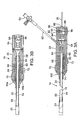
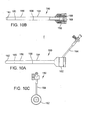
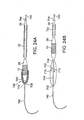
- FIG. 1 is side view of an endovascular delivery apparatus for implanting a prosthetic valve, according to one embodiment.
- FIG. 2A is side view of the balloon catheter of the delivery apparatus of FIG. 1 , shown partially in section.
- FIG. 2B is an enlarged, cross-sectional view of the balloon catheter shown in FIG. 2A , taken along the length of the catheter.
- FIG. 3A is a cross-sectional view of the guide catheter of the delivery apparatus of FIG. 1 , taken along a plane extending along the length of the guide catheter.
- FIG. 3 B is a cross-sectional view of the guide catheter, taken along a plane that is perpendicular to the plane defining the cross-section view shown in FIG. 3A .
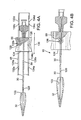
- FIG. 4A is a cross-sectional view of the nose catheter of the delivery apparatus shown in FIG. 1 , taken along the length of the nose catheter.
- FIG. 4B is an enlarged, cross-sectional view of the nose catheter.
- FIGS. 5A and 5B are cross-sectional and perspective views, respectively, of a slide nut used in the handle portion of the guide catheter.
- FIGS. 6A and 6B are perspective and side views, respectively, of an inner sleeve used in the handle portion of the guide catheter.
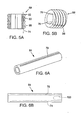
- FIG. 7A is a cross-sectional view of a guide catheter, according to one embodiment, taken along the length thereof.
- FIG. 7B is a transverse cross-sectional view of the guide catheter shown in FIG. 7A .
- FIG. 7C is an enlarged, longitudinal cross-sectional view of the distal end portion of the guide catheter shown in FIG. 7A .
- FIGS. 8A-8C are cross-sectional views of the distal end portion of the delivery apparatus of FIG. 1 , illustrating the operation of the same for implanting a prosthetic valve.
- FIG. 9 is side view of an endovascular delivery apparatus for implanting a prosthetic valve, according to another embodiment.
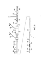
- FIG. 10A is a side view of the introducer sheath of the deliver apparatus shown in FIG. 9 .
- FIG. 10B is a side view of the introducer sheath of FIG. 10A shown partially in section.
- FIG. 10C is an end view of the introducer sheath of FIG. 10A .
- FIG. 11 is a perspective view of an alternative embodiment of a guide catheter.
- FIG. 12 is a top plan view of the guide catheter of FIG. 11 .
- FIG. 13 is a side elevation view of the guide catheter of FIG. 11 .
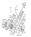
- FIG. 14 is a perspective, exploded view of the guide catheter of FIG. 11 .
- FIG. 15 is a partial, cross-sectional view of the guide catheter of FIG. 11 .
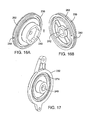
- FIGS. 16A and 16B are perspective views of a pulley used in the guide catheter of FIG. 11 .
- FIG. 17 is a perspective view of a lever portion used in the guide catheter of FIG. 11 .
- FIGS. 18A and 18B are partial, cross-sectional views of the guide catheter of FIG. 11 illustrating the operation of an adjustable lever for adjusting the curvature of the guide catheter.
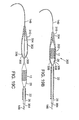
- FIG. 19A is a perspective view of the distal end portion of alternative embodiment of a nose catheter.
- FIGS. 19B and 19C are cross-sectional views illustrating the operation of the nose catheter shown in FIG. 19A .
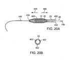
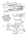
- FIG. 20A is a side elevation view of the distal end portion of a delivery apparatus, according to another embodiment.
- FIG. 20B is a transverse cross-sectional view of the guide catheter of the delivery apparatus of FIG. 20A .
- FIGS. 21A-21C are cross-sectional views of an alternative embodiment of a delivery apparatus, illustrating the operation of the same for implanting a prosthetic valve.
- FIGS. 22A and 22B are cross-sectional views of the distal end portion of another embodiment of a delivery apparatus.
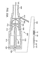
- FIG. 23A shows a cross-sectional view of another embodiment of an introducer sheath and an exemplary delivery apparatus that can be introduced into a patient's vasculature via the sheath.
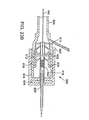
- FIG. 23B is a cross-sectional view of the introducer sheath of FIG. 23A after insertion of the delivery apparatus into the sheath.
- FIGS. 24A-24B are cross-sectional views of another embodiment of a delivery apparatus.
- FIGS. 25A-25E schematically illustrate another embodiment of a delivery apparatus.
- FIGS. 26A-26E schematically illustrate another embodiment of an introducer sheath.
- FIG. 1 shows a delivery apparatus 10 adapted to deliver a prosthetic heart valve 12 (e.g., a prosthetic aortic valve) to a heart, according to one embodiment.
- the apparatus 10 generally includes a steerable guide catheter 14 (also referred to as a flex catheter), a balloon catheter 16 extending through the guide catheter 14, and a nose catheter 18 extending through the balloon catheter 16.
- the guide catheter 14, the balloon catheter 16, and the nose catheter 18 in the illustrated embodiment are adapted to slide longitudinally relative to each other to facilitate delivery and positioning of the valve 12 at an implantation site in a patient's body, as described in detail below.
- the guide catheter 14 includes a handle portion 20 and an elongated guide tube, or shaft, 22 extending from the handle portion 20.
- the balloon catheter 16 includes a proximal portion 24 adjacent the handle portion 20 and an elongated shaft 26 that extends from the proximal portion 24 and through the handle portion 20 and the guide tube 22.
- An inflatable balloon 28 is mounted at the distal end of the balloon catheter.
- the valve 12 is shown mounted on the balloon 28 in a crimped state having a reduced diameter for delivery to the heart via the patient's vasculature.
- the nose catheter 18 includes an elongated shaft 30 that extends through the proximal portion 24, the shaft 26, and the balloon 28 of the balloon catheter.
- the nose catheter 18 further includes a nose piece 32 mounted at the distal end of the shaft 30 and adapted to receive a distal end portion of the balloon when the apparatus 10 is used to advance the valve through the patient's vasculature to the implantation site.
- the balloon catheter 16 in the illustrated configuration further includes an inner shaft 34 ( FIG. 2B ) that extends from the proximal portion 24 and coaxially through the outer shaft 26 and the balloon 28.
- the balloon 28 can be supported on a distal end portion of the inner shaft 34 that extends outwardly from the outer shaft 26 with a proximal end portion 36 of the balloon secured to the distal end of the outer shaft 26 (e.g., with a suitable adhesive).
- the outer diameter of the inner shaft 34 is sized such that an annular space is defined between the inner and outer shafts along the entire length of the outer shaft.
- the proximal portion 24 of the balloon catheter can be formed with a fluid passageway 38 that is fluidly connectable to a fluid source (e.g., a water source) for inflating the balloon.
- a fluid source e.g., a water source
- the fluid passageway 38 is in fluid communication with the annular space between the inner shaft 34 and the outer shaft 26 such that fluid from the fluid source can flow through the fluid passageway 38, through the space between the shafts, and into the balloon 28 to inflate the same and deploy the valve 12.
- the proximal portion 24 also defines an inner lumen 40 that is in communication with a lumen 42 of the inner shaft 34.
- the lumens 40, 42 in the illustrated embodiment are sized to receive the shaft 30 of the nose catheter.
- the balloon catheter 16 also can include a coupler 44 connected to the proximal portion 24 and a tube 46 extending from the coupler.
- the tube 46 defines an internal passage which fluidly communicates with the lumen 40.
- the balloon catheter 16 also can include a slide support 48 connected to the proximal end of the coupler 44.
- the slide support 48 supports and cooperates with an adjustment ring 50 ( FIGS. I and 4A-4B ) of the nose catheter 18 to allow the nose catheter to be maintained at selected longitudinal positions relative to the balloon catheter 16, as described in greater detail below.
- the outer surface of the outer shaft 26 can include one or more annular grooves or notches 52a, 52b, 52c spaced apart from each other along the proximal end portion of the shaft 26.
- the grooves cooperate with a locking mechanism 84 of the guide catheter 14 ( FIGS. 3A-3B ) to allow the guide catheter 14 to be maintained at selected longitudinal positions relative to the balloon catheter 16, as described in greater detail below.
- the inner shaft 34 and the outer shaft 26 of the balloon catheter can be formed from any of various suitable materials, such as nylon, braided stainless steel wires, or a polyether block amide (commercially available as Pebax ® ).
- the shafts 26, 34 can have longitudinal sections formed from different materials in order to vary the flexibility of the shafts along their lengths.
- the inner shaft 34 can have an inner liner or layer formed of Teflon ® to minimize sliding friction with the nose catheter shaft 30.
- the guide catheter 14 is shown in greater detail in FIGS. 3A and 3B .
- the guide catheter 14 includes a handle portion 20 and an elongated guide tube, or shaft, 22 extending distally therefrom.
- the guide tube 22 defines a lumen 54 sized to receive the outer shaft 26 of the balloon catheter and allow the balloon catheter to slide longitudinally relative to the guide catheter.
- the distal end portion of the guide tube 22 comprises a steerable section 56, the curvature of which can be adjusted by the operator to assist in guiding the apparatus through the patient's vasculature, and in particular, the aortic arch.
- the guide catheter desirably includes a cover, or shroud, 23 secured to the distal end of the guide tube 22.
- the cover 23 in particular embodiments is sized and shaped to receive the valve 12 crimped around the balloon and to abut against the proximal end surface of the nose piece 32, which is adapted to cover a distal end portion of the balloon 28 (as shown in FIG. 8A ).
- the valve 12 and the balloon 28 can be completely enclosed within the cover 23 and the nose piece 32.
- the handle portion 20 includes a main body, or housing, 58 formed with a central lumen 60 that receives the proximal end portion of the guide tube 22.
- the handle portion 20 can include a side arm 62 defining an internal passage which fluidly communicates with the lumen 60.
- a stopcock 63 can be mounted on the upper end of the side arm 62.
- the handle portion 20 is operatively connected to the steerable section 56 and functions as an adjustment to permit operator adjustment of the curvature of the steerable section 56 via manual adjustment of the handle portion.
- the handle portion 20 includes an inner sleeve 64 that surrounds a portion of the guide tube 22 inside the handle body 58.
- a threaded slide nut 68 is disposed on and slidable relative to the sleeve 64.
- the slide nut 68 is formed with external threads that mate with internal threads of an adjustment knob 70.
- the slide nut 68 is formed with two slots 76 formed on the inner surface of the nut and extending the length thereof.
- the sleeve 64 is also formed with longitudinally extending slots 78 that are aligned with the slots 76 of the slide nut 68 when the slide nut is placed on the sleeve. Disposed in each slot 78 is a respective elongated nut guide 66a, 66b ( FIG. 3B ), which can be in the form of an elongated rod or pin.
- the nut guides 66a, 66b extend radially into respective slots 76 in the slide nut 68 to prevent rotation of the slide nut 68 relative to the sleeve 64.
- rotation of the adjustment knob 70 causes the slide nut 68 to move longitudinally relative to the sleeve 64 in the directions indicated by double-headed arrow 72.
- One or more pull wires 74 connect the adjustment knob 70 to the steerable section 56 to produce movement of the steerable section upon rotation of the adjustment knob.
- the proximal end portion of the pull wire 74 can extend into and can be secured to a retaining pin 80 ( FIG. 3A ), such as by crimping the pin 80 to the pull wire.
- the pin 80 is disposed in a slot 82 in the slide nut 68 (as best shown in FIG. 5A ).
- the pull wire 74 extends from pin 80, through a slot 98 in the slide nut, a slot 100 in the sleeve 64, and into and through a pull wire lumen in the shaft 22 ( FIG. 3A ).
- the distal end portion of the pull wire 74 is secured to the distal end portion of the steerable section 56.
- the pin 80 which retains the proximal end of the pull wire 74, is captured in the slot 82 in the slide nut 68.
- the pull wire 74 also is moved in the proximal direction.
- the pull wire pulls the distal end of the steerable section 56 back toward the handle portion, thereby bending the steerable section and reducing its radius of curvature.
- the friction between the adjustment knob 70 and the slide nut 68 is sufficient to hold the pull wire taut, thus preserving the shape of the bend in the steerable section if the operator releases the adjustment knob 70.
- the steerable section 56 in its non-deflected shape is slightly curved and in its fully curved position, the steerable section generally conforms to the shape of the aortic arch. In other embodiments, the steerable section can be substantially straight in its non-deflected position.
- the handle portion 20 can also include a locking mechanism 84 that is configured to retain the balloon catheter 16 at selected longitudinal positions relative to the guide catheter 14.
- the locking mechanism 84 in the illustrated configuration comprises a push button 86 having an aperture 88 through which the outer shaft 26 of the balloon catheter extends.
- the button 86 has a distal end portion 90 that is partially received in an internal slot 92.
- a coil spring 94 disposed in the slot 92 bears against and resiliently urges the distal end portion 90 toward the shaft 26.
- the distal end portion 90 can be formed with a small projection 96 that can nest within any of grooves 52a, 52b, 52c on the shaft 26 ( FIG. 2A ).
- the spring 94 urges the projection into the groove to retain the shaft 26 at that longitudinal position relative to the guide catheter (as depicted in FIG. 3A ). Since the grooves in the illustrated embodiment extend circumferentially completely around the shaft 26, the balloon catheter can be rotated relative to the guide catheter when the longitudinal position of the balloon catheter is locked in place by the button 86. The position of the balloon catheter can be released by pressing inwardly on the button 86 against the bias of the spring 94 to remove the projection 96 from the corresponding groove on the shaft 26.
- the handle portion 20 can have other configurations that are adapted to adjust the curvature of the steerable section 56.
- One such alternative handle configuration is shown co-pending U.S. Patent Application No. 11/152,288 (published under Publication No. US2007/0005131 ), which is incorporated herein by reference.
- Another embodiment of the handle portion is described below and shown in. FIGS. 11-15 .
- FIGS. 7A and 7B show the guide catheter shaft 22 constructed in accordance with one specific embodiment.
- the shaft 22 in the illustrated embodiment comprises a tubular inner liner 104 made of a low-friction polymeric material, such as PTFE.
- the liner 104 is sized to allow a deflated balloon 28 and the balloon catheter shaft 26 to be inserted therethrough.
- a smaller conduit, or liner 106 which extends along the outside of the inner liner 104, defines a lumen through which the pull wire 74 extends.
- An outer layer 108 surrounds the liners 104, 106 and imparts the desired flexibility and stiffness to the shaft 22.
- the outer layer 108 in the illustrated embodiment comprises a braided layer formed from braided metal wire 110 wound around the liner 104 and the conduit 106, and a polymeric material 112 surrounding and encapsulating the braided metal wire layer.
- the shaft can be formed by forming the liners 104, 106, placing the liners side-by-side in a parallel relationship relative to each other, wrapping the metal wire around the liners to form the braided layer, placing a polymeric sleeve over the braided layer, and reflowing the sleeve to form a uniform laminate layer 108 surrounding the liners.
- the polymeric material 112 comprises any suitable material, but desirably comprises a thermoplastic elastomer, such as Pebax ® .
- the braided metal layer can be constructed from stainless steel wire.
- the shaft 22 desirably comprises a relatively stiff section 114 extending from the proximal end 116 of the shaft to the proximal end 118 of the steerable section 56.
- the length of the steerable section 56 comprises about 1 ⁇ 4 of the overall length of the shaft 22.
- the overall length of the shaft 22 is about 45 inches (including the steerable section) and the length of the steerable section is about 11.7 inches, although the overall length of the shaft and/or the length of the steerable section can be varied depending on the particular application.
- the steerable section 56 of the shaft desirably is formed from a relatively soft durometer material 112 to allow the steerable section to bend upon adjustment of the adjustment knob 70, as described above.
- the stiff section 114 desirably is formed from a relatively stiffer polymeric material 112 that resists bending when the pull wire is tensioned by the adjustment knob 70.
- the stiff section 114 desirably exhibits sufficient rigidity to allow the operator to push the apparatus 10 through a potentially constricting body vessel.
- the polymeric material 112 of the steerable section comprises 55D Pebax ® and the polymeric material 112 of the remaining section 114 of the shaft comprises 72D Pebax ® , which is stiffer than 55D Pebax ® .
- the metal braided layer in the steerable section 56 can be replaced with a metal coil (e.g., a stainless steel coil) disposed on the inner liner 104 to enhance the flexibility of the steerable section.
- a metal coil e.g., a stainless steel coil
- the braided metal layer extends along the stiff section 114 and the metal coil extends along the steerable section 56.
- the metal braided layer in the steerable section 56 can be replaced with a stainless steel hypotube that is formed with laser-cut, circumferentially extending openings, such as disclosed in co-pending U.S. Patent Application No. 11/152,288 .
- the distal end of the shaft 22 can include a flared, or enlarged, end portion 116.
- the outer diameter D of the end portion 116 is equal to or about the same as the outer diameter of the crimped valve 12 supported on the balloon 28. Accordingly, when the valve 12 is advanced through an introducer sheath, the end portion 116 pushes against the crimped valve 12, rather than the balloon 28. This minimizes inadvertent movement between the balloon catheter and the valve, which can cause the position of the valve on the balloon to move.
- the shaft 22 has an outer diameter of about 16 F to about 18 F and the end portion 116 has an outer diameter D of about 22 F.
- the enlarged end portion 116 can be made of any of various suitable materials.
- the end portion 116 can be molded from Pebax ® ( e . g ., 55D Pebax ® and reflowed on the end portion of the steerable section 56.
- the distal end of the pull wire 74 is secured at the distal end of the steerable section 56. As best shown in FIG. 7C , this can be achieved by securing the distal end portion of the pull wire 74 to a metal ring 118 embedded in the outer layer 108 of the shaft, such as by welding the pull wire to the metal ring.
- the guide catheter shaft 22 can include a cover 23 for covering the valve 12 and the balloon 28 (or a portion thereof) during delivery of the valve.
- a cover 23 for covering the valve 12 and the balloon 28 (or a portion thereof) during delivery of the valve.
- an introducer sheath can be optional if the valve is covered upon insertion into the patient's vasculature.
- the nose catheter 18 includes an adjustment ring 50 at its proximal end and a nose piece 32 at its distal end, and an elongated shaft 30 extending therebetween.
- the shaft 30 desirably is formed with a lumen 120 extending the length of the shaft for receiving a guide wire 140 ( FIG. 8A ) so that the apparatus 10 can be advanced over the guide wire after it is inserted into the delivery path in the body.
- the nose piece 32 desirably is formed with an opening or cavity 122 sized and shaped to receive at least a distal end portion of the balloon 28.
- the adjustment ring 50 is disposed on and slidable relative to the slide support 48 of the balloon catheter, which function as a locking or retaining mechanism for retaining the nose catheter at selective longitudinal positions relative to the balloon catheter.
- the shaft 30 extends through and is fixedly secured to a shaft support 124 disposed within the side support 48.
- the adjustment ring 50 is secured to the shaft support 124 by screws 126, which extend through elongated slots 128a, 128b in the slide support 48. Slots 128a, 128b extend longitudinally along the length of the slide support 48.
- the shaft support 124 and the shaft 30 are caused to move in the same direction so as to adjust the longitudinal position of the nose catheter relative to the balloon catheter.
- the slot 128a is formed with circumferentially extending notches 132a-132d and the slot 128b is formed with similar circumferentially extending notches 134a-134d opposite the notches 132a-132d.
- the adjustment ring 50 is moved to align the screws 126 with a pair of diametrically opposed notches and then rotated slightly to position the screws 126 in the notches.
- FIG. 4A shows the screws 126 positioned in notches 132b and 134b. The notches restrict movement of the screws 126, and therefore the shaft support 124 and the shaft 30, in the distal and proximal directions.
- each slot 128a, 128b is formed with four notches.
- the nose piece 32 is retained at a position covering a distal end portion of the balloon 28 and abutting the cover 23 of the guide catheter 14 such that the balloon 28 and the valve 12 are completely enclosed by the cover 23 and the nose piece 32 ( FIG. 8A ).
- the nose piece 32 is retained at a position spaced distally a first distance from the balloon 28 so that the valve can be deployed by inflating the balloon without inference from the nose piece ( FIG. 8C ).
- the nose piece When the screws are positioned in notches 132a, 134a, the nose piece is retained at a position spaced distally a second distance, greater than the first distance, from the balloon 28. In this position, the balloon 28 can be refolded inside the cover 23 (after valve deployment) without interference from the nose piece.
- the valve 12 can take a variety of different forms.
- the valve generally comprises an expandable stent portion that supports a valve structure.
- the stent portion desirably has sufficient radial strength to hold the valve at the treatment site and resist recoil of the stenotic native valve leaflets. Additional details regarding balloon expandable valve embodiments can be found in U.S. Pat. Nos. 6,730,118 and 6,893,460 , each entitled IMPLANTABLE PROSTHETIC VALVE, which are incorporated by reference herein.
- the delivery system may be used with self-expanding prosthetic valves. For example, when using a self-expanding valve, a pusher may be used to assist in ejecting the self-expanding valve from a delivery sleeve that maintains the valve in its compressed state.
- the valve 12 When the valve 12 is used to replace the native aortic valve (or a previously implanted, failing prosthetic aortic valve), the valve 12 can be implanted in a retrograde approach where the valve, mounted on the balloon in a crimped state, is introduced into the body via the femoral artery and advanced through the aortic arch to the heart.
- a guide wire 140 FIG. 8A
- the guide wire 140 can be placed in the body vessel through a dilator (not shown), which expands the inner diameter of the body vessel for introducing the delivery device. Dilator diameters range between, for example, 12 and 22 French.
- the valve 12 can be positioned inside the cover 23 with the nose piece 32 covering the distal end portion of the balloon 28 and abutting the distal end of the cover 23.
- the adjustment ring 50 of the nose catheter can be locked in place to retain nose piece 32 against the cover 23 during delivery.
- the nose catheter desirably is placed in slight tension with the nose piece 32 held tightly against the cover 32 to inhibit separation of the nose piece from the cover while tracking the device through the vasculature and during removal of the delivery apparatus from the body.
- the valve 12 in the illustrated embodiment can be completely covered by the cover 23, an introducer sheath is not needed to introduce the valve into the body vessel.
- An introducer sheath having a diameter of about 22 to 24 French typically is used in a retrograde procedure.
- the cover 23 desirably has an outer diameter that is less than the outer diameter of the introducer sheath, and in particular embodiments, the outer diameter of the cover 23 is in the range of about 0.260 inch to about 0.360 inch, with about 0.330 inch being a specific example.
- the cover 23 which represents the largest diameter of the delivery device, need only be in contact with the femoral and iliac arteries for only a very short period of time, trauma to these vessels can be minimized.
- the cover 23 can be shorter in length so that less of the outer surface of the valve and the balloon is covered by the cover 23 during delivery.
- the cover 23 can be dimensioned to extend over only a proximal end portion of the balloon or a proximal end portion of the valve.
- the guide catheter 14 is used to "steer" the apparatus away from the inner surface of the aorta.
- the tapered distal end portion of the nose piece 32 assists in tracking through the femoral and iliac arteries, as well as provides atraumatic tracking through over the aortic arch and smooth crossing of the native aortic valve.
- the nose piece 32 in the illustrated embodiment is mounted on separate nose catheter 18 that can be moved relative to the valve 12.
- the nose piece 32 therefore can be mounted over the distal end portion of the balloon during delivery in order to minimize the length of the non-steerable section at the distal end of the delivery device. This allows for easier tracking through the aortic arch with little or no contact between the end of the delivery device and the inner walls of the aorta.
- the length L ( FIG. 8A ) of the non-steerable section at the end of the delivery device is about 6 cm or less.
- the operator can track the positions of marker bands 142 ( FIGS. 2A and 2B ) on the guide wire shaft 34 in order to position the valve at the implantation site.
- the nose catheter can be moved distally relative to the balloon catheter to advance the nose piece 32 distally away from the balloon 28 ( FIG. 8B ) and the guide catheter can be moved proximally relative to the balloon catheter to expose the valve 12 from the cover 23 ( FIG. 8C ).
- the longitudinal positions of the nose catheter and the guide catheter can be fixed relative to the balloon catheter while the operator adjusts the position of and then deploys the valve 12. Inflation of the balloon 28 is effective to expand the valve 12 to engage the native valve leaflets.
- the balloon 28 can then be deflated and retracted back into the cover 23 and the nose piece 32 can be pulled back over the distal end portion of the balloon.
- the entire delivery apparatus can then withdrawn back over the guide wire 140 and removed from the body, after which the guide wire can be removed from the body.
- FIG. 9 shows an alternative embodiment of the delivery apparatus 10.
- the guide catheter 14 is not provided with a cover 23 (as previously illustrated in FIGS. 3A and 3B ) and instead an introducer sheath 150 can be used to introduce the delivery apparatus into the body.
- the introducer sheath 150 in the illustrated embodiment includes an introducer housing 152 and an introducer sleeve 154 extending from the housing 152.
- the housing 152 houses a sealing valve 166.
- the sleeve 154 is inserted into a body vessel (e.g., the femoral artery) while the housing 152 remains outside the body.
- the delivery apparatus 10 is inserted through a proximal opening 168 in the housing, the sealing valve 166, the sleeve 154 and into the body vessel.
- the scaling valve 166 sealingly engages the outer surface of the guide catheter shaft 22 to minimize blood loss.
- the sleeve 154 can be coated with a hydrophilic coating and extends into the body vessel about 9 inches, just past the iliac bifurcation and into the abdominal aorta of the patient.
- the sleeve 154 can have a tapered section 156 that tapers from a first diameter at a proximal end 158 to a second, smaller diameter at a distal end 160.
- a reduced diameter distal end portion 162 extends from the tapered portion 156 to the distal end of the sleeve 154.
- the tapered portion 156 provides for a smoother transition between the outer surface of the sleeve 154 and the outer surface of the guide shaft 22 of the guide catheter 14.
- the tapered portion 156 also allows for variable placement of the sleeve 154 in the patient's vasculature to help minimize complete occlusion of the femoral artery.
- FIGS. 11-15 show an alternative embodiment of a handle portion, indicated at 200, that can be used in the guide catheter 14 ( FIGS. 1 and 3A ), in lieu of handle portion 20.
- the handle portion 200 in the illustrated embodiment includes a main housing 202 and an adjustment lever 204 pivotably connected to the housing 202.
- the lever 204 can be pivoted distally and proximally (as indicated by double-headed arrow 206 in FIG. 13 ) to adjust the curvature of the shaft 22, as further described below.
- the housing 202 can be formed from first and second housing portions 208, 210 that can be secured to each other using a suitable adhesive, mechanical fasteners, a snap fit connection, or other suitable techniques.
- a seal housing 212 Disposed within the housing 202 is a seal housing 212 that has a central bore 226 extending therethrough. The distal end portion of the bore 226 can form an enlarged portion that receives the proximal end portion 214 of the shaft 22.
- the shaft 22 extends from the seal housing 212 through the main housing 202 and out of a nose piece 228 connected to the distal end of the main body 202.
- An end piece 216 can be connected to the proximal end of the seal housing 212 with a seal 218 captured between these two components.
- the end piece 216 can be formed with a stepped bore shaped to receive the seal 218 and an end portion of the seal housing 212.
- the seal 218 can be made of a suitable elastomer, such as silicon.
- the shaft 26 of the balloon catheter 16 extends through the end piece 216, a central opening in the seal 218, the seal housing 212, and the guide catheter shaft 22.
- the seal housing 212 can be formed with a flush port 220 that is in fluid communication with the central bore 226.
- the flush port 220 receives one end of a flexible tube 222.
- the opposite end of the tube 222 can be connected to a stopcock 224 ( FIG. 11 ).
- the lever 204 in the illustrated configuration comprises first and second lever portions 230, 232, respectively, mounted on opposite sides of the main housing 202.
- the inner surface of each lever portion can be formed with an annular groove 274 adapted to receive a respective O-ring 234.
- the lever portion 230 can be coupled to a pulley 236 mounted in the housing to produce rotation of the pulley upon pivoting movement of the lever portion.
- the lever portion 230 can be formed with a projection 238 that extends through the housing portion 208 and into a complementary shaped recess 240 ( FIG.16A ) in the pulley 236.
- the projection 236 can be formed with flats on its outer surface that engage corresponding flats in the recess 240 to produce rotation of the pulley when the lever is activated.
- the pulley 236 can also be formed with a non-circular recess or opening 242 that is shaped to receive one end portion of a shaft 244 ( FIG. 14 ).
- the opposite end of the shaft 244 extends through the second housing portion 210 and into a complementary shaped recess or opening 246 of the lever portion 232 ( FIG. 17 ).
- the end portions of the shaft 244 and the corresponding openings 242 and 246 are hexagonal to inhibit relative rotation between the shaft 244, the pulley 236, and the lever portion 232, although various other non-circular shapes can be used.
- the end portions of the shaft and the openings 242, 246 can be circular if the shaft is otherwise fixed against rotation relative to the pulley and the lever portion.
- Upper and lower cross-bars 248, 250 are connected to and extend between respective upper and lower ears of the first and second lever portions 230, 232. Screws 252 extending through the ears of the lever portions 230, 232 and tightened into the cross-bars 248, 250 can be used to secure the components of the lever 204 to the main body 202.
- a screw 254 can extend through the lever portion 230, the housing portion 208, and into a threaded opening in the shaft 244.
- An adjustment knob 266 can be fixedly secured to a screw 268, which can extend through the lever portion 232, the housing portion 210, and into a threaded opening in the opposite end of the shaft 244.
- the screw 268 can be fixedly secured to the adjustment knob, for example, by adhesively securing the head of the screw within a recess (not shown) on the inner surface of the adjustment knob. Consequently, the adjustment knob 266 can be manually rotated to loosen or tighten the screw into the shaft 244 to adjust the rotational friction of the pulley 236.
- a pull wire 74 extends through a pull wire lumen in the shaft 22 and extends from the shaft inside of the main housing 202.
- a flexible tension member 256 such as a piece of string, is tied off or otherwise connected to at one thereof to the end of the pull wire 74.
- the tension member 256 extends around a cross-member 258, partially around the outer circumference of the pulley 236, through a radially extending opening 260 in the pulley and is tied off or otherwise connected to the shaft 244 adjacent the center of the pulley 236.
- the pulley 236 can be formed with an annular groove or recess 262 adapted to receive the tension member 256.
- FIG. 18A shows the adjustment lever 204 in a forward-most position.
- the steerable section 56 of the shaft 22 is in its normal, non-deflected state (e.g., straight, such as shown in FIG. 1 , or slightly curved).
- the pulley 236 is rotated clockwise in the illustrated embodiment, causing the tension member to wind around the pulley and pull the pull wire 74 rearwardly.
- the pull wire 74 pulls on the distal end of the shaft to adjust the curvature of the steerable section 56, in the manner previously described.
- FIG. 18B shows the lever 204 in a rearward-most position corresponding to the fully curved position of the steerable section of the shaft 22.
- the rotational friction of the pulley 236 is sufficient to hold the pull wire taut, thus preserving the shape of the bend in the steerable section if the operator releases the adjustment lever 204.
- tension in the pull wire is released.
- the resiliency of the steerable section 56 causes the steerable section to return to its normal, non-deflected shape as tension on the pull wire is released. Because the tension member 256 in the illustrated embodiment does not apply a pushing force to the pull wire, movement of the lever 204 toward the forward-most position does not cause buckling of the pull wire.
- the adjustment knob 266 can be adjusted by the operator to vary the rotational friction of the pulley 236.
- the rotational friction desirably is adjusted such that if the guide catheter is pulled back inadvertently while in the patient's vasculature, the pulley can rotate toward the forward-most position under a forward pulling force of the pull wire (as indicated by arrow 270 in FIG. 18B ) to allow the steerable section to straighten out as it is pulled through the vasculature, minimizing trauma to the vasculature walls.
- the adjustment lever 204 in the illustrated embodiment provides a substantially l:1 deflection of the steerable section in response to movement of the lever; that is, rotation of the lever 204 causes a substantially l:1 movement of the pull wire and therefore the steerable section 56.
- the adjustment lever 204 provides the operator tactile feedback of the curvature of the steerable section to facilitate tracking through the vasculature.
- the lever is ergonomically positioned for maintaining the proper orientation of the guide catheter during use.
- Another advantage of the illustrated handle portion 200 is that the proximal portion 24 of the balloon catheter 16 ( FIG. 2B ) or a portion thereof can seat within the end piece 216 to minimize the working length of the balloon catheter.
- FIGS. 19A and 19B illustrate an alternative nose catheter 300, according to one embodiment, that can used with the delivery apparatus 10 (F1G. 1), in lieu of the nose catheter 18.
- the nose catheter 300 in the illustrated configuration includes a nose piece or valve cover 302 connected to a nose catheter shaft 304.
- the valve cover 302 is adapted to cover the balloon 28 and a valve 12 mounted on the balloon.
- the guide catheter 14 need not have a cover 23 ( FIG. 8A ) to cover the valve during delivery.
- the shaft 304 is fixedly secured at its distal end to the distal end of the cover 302 and extends through the balloon 28 and the balloon catheter shaft 26.
- the shaft 304 can have a lumen to receive a guide wire 140.
- the shaft 304 can move longitudinally relative to the balloon catheter and the guide catheter, much like the nose catheter 18 previously described.
- the cover 302 has a proximal end portion 306 formed with a plurality of slits defining triangular flaps 308.
- the flaps 308 can flex radially outwardly from each other to form an opening large enough to allow passage of the balloon 28 and the valve 12 when it is desired to deploy the valve.
- the proximal end portion 306 can be tapered as shown to facilitate retraction of the cover 302 back into an introducer sheath.
- the tapered shape of the end portion 306 also provides an atraumatic surface to minimize trauma to the vasculature walls when the delivery apparatus is withdrawn from the body.
- the cover also can have a tapered distal end portion 310 to assist in tracking through the femoral and iliac arteries, as well as provide atraumatic tracking through the aortic arch and smooth crossing of the native aortic valve.
- the cover 302 desirably is made from a flexible material, such as nylon, Pebax ® , or PET and can have a wall thickness in the range of about 0.0015 inch to about 0.015 inch.
- the delivery apparatus is advanced over the guide wire 140 until the valve is positioned at or near the deployment location.
- the nose catheter 300 is then advanced distally relative to the balloon catheter 16 to uncover the balloon and the valve 12, as illustrated in FIG. 19C .
- the cover 302 is advanced distally, the balloon and the valve can pass through the proximal opening formed by flaps 308. Once the valve 12 is exposed, the balloon 28 can be inflated to deploy the valve.
- FIG. 20A shows a modification of the guide catheter 14 where the valve cover 23 is replaced with an expandable mesh basket or cover 400 connected to the distal end of the guide catheter shaft 22.
- the cover 400 is sized and shaped to cover the valve 12 and the balloon 28.
- a nose catheter e.g., nose catheter 18
- the cover 400 can have a braided mesh construction formed from metal wire (e.g., Nitinol or stainless steel wires).
- One or more ribbon wires 402 are connected to the distal end 404 of the cover 400 and extend through respective lumens in the guide catheter shaft 22 along the length thereof ( FIG. 20B ).
- the wires 402 can be, for example, .003 inch x .020 inch Nitinol ribbon wire.
- the wires 402 are connected at their proximal ends to a handle portion of the guide catheter that allows the operator to apply pushing or pulling forces to the wires. Pushing the wires 402 forward, in the direction of arrow 406, causes the cover to collapse over the balloon 28 and the valve 12 to provide a smooth tracking profile. Pulling the wires 402 rearward, in the direction of arrow 408, causes the cover to expand and allows the balloon and valve to be advanced outwardly through an opening at the distal end 404 of the cover 400.
- the cover 400 is placed in a collapsed state covering the valve and the balloon for delivery through the patient's vasculature to the deployment site.
- the wires 402 are then pulled in the proximal direction (as indicted by arrow 408) to expand the cover 400.
- the guide catheter can then be pulled in the proximal direction to advance the balloon and the valve from the distal end of the cover.
- the balloon catheter 16 can be advanced distally relative to the guide catheter 14 to advance the balloon and the valve from the cover 400.
- FIGS. 21A-21C show an alternative embodiment of a delivery apparatus, indicated at 500.
- the delivery apparatus 500 allows a valve 12 to be mounted on a balloon 28 of a balloon catheter inside a body vessel.
- the balloon catheter can have a construction similar to the balloon catheter shown in FIGS. 2A and 2B except that in the embodiment of FIGS. 21A-21B , the balloon catheter shaft 26 has a distal end portion 504 that extends distally from the bal loon 28 and an annular tapered wedge 502 is disposed on the distal end portion 504 adjacent the balloon.
- the tapered wedge 502 functions to expand the valve to facilitate positioning the same on the balloon inside the body, as further described below.
- the wedge 502 desirably is made from a low-friction material, such as nylon, to allow the valve to easily slide over the wedge and onto the balloon.
- the delivery apparatus includes a nose catheter comprising a shaft 506 and a nose piece 508 connected to the distal end of the shaft 506.
- the nose catheter shaft 506 can have a guide wire lumen to receive a guide wire 140 so that the apparatus can be advanced over the guide wire with the guide wire passing through the lumen.
- the delivery apparatus 500 can further include a guide catheter comprising a guide catheter shaft 22 and an elongated cover 510 extending from the distal end of the shaft 22.
- the nose catheter, balloon catheter, and guide catheter are moveable longitudinally relative to each other and can have locking mechanisms at the proximal end of the apparatus for retaining the catheters at selected longitudinal positions relative to each other, as described in detail above.
- the valve 12 is initially mounted in a crimped state on the nose catheter shaft 506 between the nose piece 508 and the tapered wedge 502, rather than on the balloon prior to inserting the delivery apparatus into the body.
- the valve is crimped onto the nose catheter shaft such that that valve can still move along the shaft when it is desired to place the valve on the balloon 28.
- the nose piece 508 can be formed with a stepped bore comprising a first bore portion 512 and a second, enlarged bore portion 514 at the proximal end of the nose piece.
- the stepped bore can be formed with an annular shoulder 516 extending between the first and second bore portions and adapted to engage the distal end of the valve 12 when the valve is inserted into the second portion 514.
- the nose piece 508 can have an outer surface that tapers in a direction toward the distal end of the nose piece 508 to provide atraumatic tracking through tortuous vasculature.
- the cover 510 which can be optional, is adapted to extend over and cover the balloon 28, the wedge 502, and at least a proximal end portion of the valve 12 when the valve is positioned on the nose catheter shaft for delivery.
- the distal end of the cover 510 can be positioned to abut the proximal end of the nose piece 508 so as to completely enclose the valve during delivery.
- the cover 510 can be shorter in length so that less of the outer surface of the valve or the balloon is covered during delivery.
- the nose piece 508 when moved proximally relative to the balloon catheter (in the direction indicated by arrow 518), pushes the valve 12 over the wedge 502 and onto the balloon 28. As the valve passes over the wedge, the valve expands slightly to facilitate positioning the same on the balloon.
- the balloon catheter shaft 26 can have radiopaque markers 520 ( FIG. 21A ) to assist the operator in aligning the valve at the proper location on the balloon.
- the nose piece can have an outer layer 522 formed from a relatively soft and flexible material and an inner layer 524 formed from a relatively harder material.
- the inner layer 524 in the illustrated embodiment forms the shoulder 516 and the inner surface of the first bore portion 512.
- the nose piece exhibits sufficient rigidity to push the valve 12 over the wedge and onto the balloon and provides a soft outer surface to minimize trauma to the body vessels.
- the outer layer 522 can be made of 55D Pebax ® and the inner layer can be made of 72D Pebax ® , which is stiffer than 55D Pebax ® .
- the section of the delivery apparatus mounting the valve typically defines the maximum outer diameter of the apparatus inserted into the body.
- the valve 12 can be crimped to a smaller diameter than if the valve is mounted on the balloon. Accordingly, the maximum outer diameter of the delivery apparatus can be reduced for insertion into and through the vasculature. As noted above, by reducing the maximum diameter of the delivery apparatus, it is less occlusive to the femoral artery and therefore the patient's leg can remain well perfused during the procedure.
- the maximum outer diameter of the cover 510 and the nose piece 508 (at its proximal end) is about .223 inch, which is the maximum diameter of the portion of the delivery apparatus that is inserted into the body.
- the wedge 502 can have a diameter at its proximal end of about 120 inch and the guide catheter shaft 22 can have an outer diameter of about .184 inch.
- the valve 12 is initially mounted on the nose catheter shaft and inserted into the nose piece 508 and the cover 510.
- the proximal end of the wire extending from the body can be inserted into the distal end of the guide wire lumen and the delivery apparatus 500 can be inserted into a body vessel (e.g., the femoral artery) and advanced through the body (as depicted in FIG. 21A ).
- a body vessel e.g., the femoral artery
- an introducer sheath can be inserted first into the body vessel, for example if a cover 510 is not provided to cover the valve 12.
- the delivery apparatus can be inserted through the introducer sheath and into the body vessel.
- the guide catheter is retracted proximally relative to the balloon catheter to advance the valve and the balloon from the cover 510.
- the valve and the balloon can be advanced into the ascending aorta or into the left ventricle where the valve can then be moved onto the balloon.
- the nose catheter can be retracted proximally to advance the valve over the wedge 502 and onto the balloon 28.
- Markers 520 FIG. 21A ) can be used to center the valve on the balloon.
- the nose catheter can be advanced distally so as not to interfere with inflation of the balloon, as shown in FIG. 21C .
- the valve can then be positioned at the implantation site (e.g., within the native aortic valve) and deployed by inflating the balloon.
- FIGS. 22A and 22B show a modification of the delivery apparatus 10 ( FIGS. 1-8 ).
- the cover 23 has a generally tubular shape but is provided in a rolled up state on the distal end portion of the guide catheter shaft 22. After the valve 12 is mounted on the balloon 28, the cover can be unrolled over the valve 12 for insertion into and through the patient's vasculature.
- the operation of the deliver apparatus shown in FIGS. 22A and 22B is otherwise identical to the operation of the delivery apparatus 10 described above with reference to FIGS. 8A-8C .
- FIGS. 23A and 23B show an embodiment of an improved introducer sheath, indicated at 600, that can be used to facilitate insertion of a delivery apparatus into a body vessel.
- the introducer sheath 600 is particularly suited for use with a delivery apparatus that is used to implant a prosthetic valve, such as the embodiments of delivery apparatus described herein.
- the introducer sheath 600 also can be used to introduce other types of delivery apparatus for placing various types of intraluminal devices (e.g., stents, stented grafts, etc.) into many types of vascular and non-vascular body lumens (e.g., veins, arteries, esophagus, ducts of the biliary tree, intestine, urethra, fallopian tube, other endocrine or exocrine ducts, etc.).
- the example illustrated in FIG. 23A shows the distal end portion of a delivery apparatus used to implant a prosthetic valve 12.
- the delivery apparatus comprises a balloon catheter and a guide catheter.
- the balloon catheter comprises a shaft 26 and a balloon 28 mounted on the distal end portion of the shaft.
- the guide catheter comprises a shaft 22 extending over the balloon catheter shaft 26.
- the remaining portions of the balloon catheter and the guide catheter can be constructed according to the embodiment shown in FIGS. 1-8 .
- a conventional introducer sheath typically requires a tubular loader to be inserted through the seals in the sheath housing to provide an unobstructed path for a valve mounted on a balloon catheter.
- the loader extends from the proximal end of the introducer sheath, thereby increasing its working length, and decreasing the available working length of a delivery apparatus that can be inserted into the body.
- the introducer sheath 600 includes a integrated loader tube housed in the sheath housing to reduce the working length of the sheath, and therefore increase the available working length of a delivery apparatus that can be inserted into the body.
- the illustrated sheath 600 includes a seal housing 602 and a tubular sleeve 604 extending distally from the housing.
- the seal housing 602 houses one or more sealing valves, such as a cross-slit valve 606, a disc valve 608, and a hemostatic valve 610 as shown in the illustrated embodiment.
- the valves desirably are fabricated from a resilient biocompatible material, such as polyisoprene, although similar biocompatible materials also can be used.
- the valves 606, 608, 610 are further shown and described in U.S. Patent No. 6,379,372 , which is incorporated herein by reference.
- a spacer 612 can be interposed between the disc valve 608 and the cross-slit valve 606.
- an end piece 614 adapted to move longitudinally along the length of the seal housing.
- the end piece has a tubular body formed with internal threads 616 that engage external threads 618 formed on the outer surface of the seal housing 602.
- the end piece 614 has a central opening 620 and an elongated loader tube 622 fixedly secured to the proximal end portion of the end piece and extending distally therefrom.
- the opening 620 and the loader tube 622 are dimensioned to permit passage of the valve 12 (or other prosthesis) mounted on the delivery apparatus.
- the end piece 614 also houses a seal 624 having a central opening aligned with the opening 620. The seal 624 sealingly engages the outer surface of the delivery apparatus when it is inserted into the introducer sheath 600.
- the end piece 614 can be adjusted inwardly and outwardly relative to the seal housing 602. adjusting the end piece 614 from the extended position shown in FIG. 23A to the retracted position shown in FIG. 23B moves the loader tube 622 through the seals 606, 608, 610 to provide an unobstructed path for the valve 12 to pass through the introducer sheath. Because the loader tube does not extend behind the end piece, as in a conventional introducer sheath, the loader tube does not decrease the available working length of the delivery apparatus that can be inserted into the vasculature.
- the introducer sheath 600 in the extended position shown in FIG. 23A can be placed on a previously inserted guide wire 140 and advanced thereon until the sleeve 604 extends into a body vessel a desired distance.
- the delivery apparatus can then be inserted through the opening 620 to position the valve 12 in the loader tube 622 with the seal 624 forming a fluid tight seal around the guide catheter shaft 22.
- the end piece 614 is rotated to slide the loader tube 622 through the valves 606, 608, 610 ( FIG. 23B ), thus placing the delivery apparatus in communication with the lumen of the sleeve 604 and the body vessel in which the sleeve is inserted.
- this approach simplifies the loading process and reduces the number of steps and parts required to load the valve into the sheath.
- the seal housing 602 can have internal threads that engage external threads on the end piece 614.
- the end piece can be rotated to adjust the position of the loader tube 622 as previously described.
- the pitch of the threads on the seal housing and the end piece can be varied to vary the amount of rotational movement required to extend the loader through the sealing valves.
- the end piece 614 can be slidingly positionable along the length of the seal housing by pushing and pulling the end piece without rotating the same.
- FIGS. 24A and 24B show another embodiment of a nose catheter, indicated at 700, that can be used in the delivery apparatus 10 ( FIG. 1 ).
- the nose catheter 700 includes a nose piece 702 and a nose catheter shaft 704.
- the nose piece 702 has a distal end 706 connected to the nose catheter shaft 704 and a proximal end connected to the distal end of a balloon catheter shaft 26.
- the nose piece 702 comprises a balloon or similar structure formed from a thin, flexible material, such as nylon or PET, capable of assuming an inverted shape covering a valve 12 and a balloon 28 or portions thereof when the nose piece 702 is urged against the balloon 28.
- the nose piece 702 can have a structure similar to the balloon 28.
- the nose catheter shaft 704 is slidable relative to the balloon catheter shaft 26, although the proximal end of the nose piece 702 is connected to the balloon catheter shaft.
- the nose catheter shaft 704 is moved proximally relative to the balloon catheter shaft 26 (in the direction of arrow 710) from a first, extended position ( FIG. 24B ) toward a second, retracted position ( FIG. 24A )
- the nose piece 702 is urged against the distal end of the balloon catheter shaft 26, causing the nose piece 702 to assume an inverted position covering a portion of the outer surface of the balloon 28 and the valve 12.
- moving the balloon catheter shaft distally relative to the nose catheter shaft from the extended position shown in FIG. 24B also is effective to cause the nose piece to assume an inverted position over the balloon and the valve.
- the nose piece 702 is initially placed in the inverted position shown in FiG. 24A to provide a smooth tracking profile during delivery of the valve through the patient's vasculature.
- the nose catheter shaft 704 is moved distally relative to the balloon catheter shaft 20 (in the direction of arrow 71.2) to uncover the valve 12 and the balloon 28 for subsequent deployment of the valve.
- the nose piece 702 can be partially inflated so that it can more readily assume the inverted position shown in FIG. 24A .
- the lumen of the nose catheter shaft 704 can be fluidly connected to a fluid source for partially inflating the nose piece 702, similar to the way the balloon catheter shaft is used to deliver a fluid to the balloon 28.
- FIG. 25A shows the distal end portion of a modification of the delivery apparatus 10.
- the delivery apparatus in this embodiment includes a stepped balloon 800 mounted on the distal end portion of the balloon catheter shaft 26 and inner shaft 34.
- the illustrated balloon 800 includes a first slender portion 802, a first conical portion 804, a main cylindrical portion 806, a second conical portion 808, a second cylindrical portion 810, a third conical portion 812, and a second slender portion 814.
- a valve 12 FIG. 25A
- the stepped balloon 800 is further described in detail in co-pending U.S. Application No. 11/252,657 (the '657 application) (published as U.S. Patent Application Publication No. 2007/0088431 ), which is incorporated herein by reference.
- the delivery apparatus includes a guide catheter comprising a guide catheter shaft 22 having an enlarged end portion 816 that abuts the proximal end of the valve 12.
- the guide catheter further includes a retractable cover 818 that extends over and covers the valve 12.
- the cover 818 is operable to slide longitudinally relative to the valve and the distal end of the guide catheter shaft 22 to uncover the valve for deployment inside a body vessel.
- Portions 802, 804 of the balloon 800 extend from the distal end of the cover 818 and can be partially inflated to provide a transition member between the distal end of the balloon catheter and the cover 818, thereby facilitating tracking through the patient's vasculature, much like nose piece 32 ( FIG. 1 ).
- the end of the balloon extending from the cover 818 also can be used as a dilator to dilate stenotic leaflets of a native heart valve or other portions of the patient's vasculature prior to deploying the valve at the desired implantation site, as further described in the '657 application.
- the cover 818 in the illustrated embodiment has a cylindrical distal end portion 820 that extends over the valve 12 and a plurality of circumferentially spaced fingers 822 extending proximally from the proximal end of the cylindrical distal end portion 820.
- the proximal end portion of each finger 822 is connected to a pull wire 826 that extends through a respective lumen in the guide catheter shaft 22.
- each pull wire 826 extends distally from a respective lumen 828, through an opening 830 in the proximal end portion 824 of a respective finger 822, and back into the lumen 828.
- the guide catheter can further include a flexible outer cover 838 extending over the portions of the pull wires 826 extending from the shaft 22 to prevent the wires from contacting the inner walls of the vasculature.
- the cover 838 can be fixedly secured to the outer surface of the shaft 22, such as with a suitable adhesive.
- the cover 838 can be adapted to slide longitudinally relative to the shaft 22.
- the cover 818 in the illustrated example has four fingers 822, each of which is connected to a pull wire 826 that extends through a respective lumen 828. As shown in FIG. 25D , the lumens 828 can be equally spaced around a central lumen 54 of the shaft 22.
- the shaft 22 also can include another lumen for receiving a pull wire 74 for adjusting the curvature of the guide catheter, as described above.
- the pull wires 826 extend the length of the guide catheter shaft 22 and are operatively connected to an adjustment mechanism at the proximal end of the shaft to permit manual adjustment of the pull wires 826, and therefore the cover 818.
- FIG. 25E is a schematic illustration of a handle portion 832 connected to the proximal end of thc guide catheter shaft.
- the handle potion 832 can have a construction similar to the handle portion 20 (described above and shown in FIGS. 3A-3B ) except that the former can include an additional adjustment mechanism 834 connected to the pull wires 826.
- the adjustment mechanism 834 can be moved fore and aft (in the directions of double-headed arrow 836) by the operator to move the pull wires 826.
- the pull wires 826 desirably exhibit sufficient rigidity to apply a pushing force to the cover 818 in the distal direction without buckling.
- the pull wires can be, for example, .006 inch x .012 inch Nitinol ribbon wire.
- the cover 818 can be retracted in the proximal direction relative to the valve, and if necessary, moved in the distal direction, such as to retrieve the valve back into the cover 818, by operation of the adjustment mechanism 834. Further details of an adjustment mechanism that can be used to produce movement of the pull wires in the distal and proximal directions is described in detail in the '657 application.
- the cover 818 When the valve is advanced to the implantation site inside the body, the cover 818 is retracted by operation of the adjustment mechanism to uncover the valve. As the cover 818 is retracted (relative to the shaft 22 and the outer cover 838), the distal end of the shaft end portion 816 abuts against the valve to prevent inadvertent movement of valve's position on the balloon 800. Thereafter, the balloon catheter can be advanced distally relative to the guide catheter to advance the balloon 800 a sufficient distance from the cover 838 and the shaft end portion 816 to permit full inflation of the balloon for deploying the valve 12.
- the valve 12 can be a balloon-expandable valve that is deployed by the balloon, or alternatively, the valve 12 can be a self-expanding valve that radially expands when advanced from the cover 818. In the latter case, the balloon 800 can be used to further expand the valve to ensure tight engagement with the orifice of the native valve.
- the shaft distal end portion 816 can be configured to provide a releasable attachment to the valve 12, such as described in detail in the '657 application.
- the guide catheter can be moved fore and aft to adjust the position of the valve in the body vessel as the valve is being deployed.
- control of valve positioning can be achieved by the operator pushing, pulling, or twisting the guide catheter. Once the operator is satisfied with the position of the valve, the valve can be fully deployed and the valve is detached from the distal end of the guide catheter shaft.
- FIGS. 25A-25E illustrate another embodiment of an introducer sheath, indicated at 900, that can be used to facilitate the introduction of a delivery apparatus into a blood vessel.
- the introducer sheath 900 has an expandable, elongated sleeve 902 that can be radially expanded from a first diameter ( FIG. 25A ) to a second, larger diameter ( FIG. 25B ) to facilitate insertion of the largest portion the delivery apparatus (the portion on which the valve or other prosthetic device is mounted).
- the sheath 900 further includes a handle portion 904 connected to the proximal end of the sleeve 902.
- the sleeve 902 includes an inner layer 906 and an outer layer 908.
- the inner layer 906 can be a braided polymeric layer made from a suitable material such as, peek, nylon, or polypropylene.
- the outer layer 908 can be formed from urethane or another suitable material.
- the outer surface of the outer layer 908 can be provided with a hydrophilic coating.
- the handle portion 904 can house one or more sealing valves configured to sealingly engage the outer surface of a delivery apparatus inserted through the sheath, as previously described.
- the sleeve 902 can be formed with a main lumen 910 sized to permit passage of a delivery apparatus and one or more inner conduits 912 defining side lumens spaced around the main lumen 910. Extending through each side lumen is a respective pull wire 914.
- the proximal end of each pull wire 914 is connected to an adjustment mechanism 916 on the handle portion 904.
- the distal end of each pull wire 914 is fixedly secured to the distal end portion of the sleeve 902.
- each pull wire 914 can extend outwardly from the distal end of a respective lumen and can be welded to the inner layer 906 adjacent the distal end of the sleeve.
- the adjustment mechanism 916 is configured to permit manual adjustment of the diameter of the sleeve 902 between a first diameter ( FIG. 25A ) and a second, larger diameter ( FIG. 25B ).
- the adjustment mechanism can move longitudinally relative to the handle portion 904, in the directions indicated by double-headed arrow 918. Moving the adjustment mechanism in the proximal direction (away from the sleeve 902) is effective to pull the pull wires 914 in the same direction, which causes the sleeve 902 to radially expand and to shorten in length.
- the sleeve 902 has an outer diameter of about 18 F in its contracted state and can expand to an outer diameter of about 28 F.
- the sleeve 902 can be inserted into a blood vessel as previously described.
- a delivery apparatus e.g., delivery apparatus 10
- the sleeve 902 can be radially expanded to allow a prosthetic valve (e.g., valve 12) or other prosthetic device mounted on the delivery apparatus to easily pass through the sleeve 902.
- a prosthetic valve e.g., valve 12
- the sleeve 902 can be reduced in diameter to minimize occlusion of the vessel.
- the inner layer 906 can be a laser cut tube rather than a braided layer.
- the tube can be formed with a plurality of longitudinally extending cuts or slits 920 that allow the tube to radially expand and contract.
- the delivery apparatus can be used for implanting prosthetic devices other than prosthetic heart valves into the body.
- the delivery apparatus can be used to deliver and deploy various types of intraluminal devices (e.g., stents, stented grafts, etc.) into many types of vascular and non-vascular body lumens (e.g., veins, arteries, esophagus, ducts of the biliary tree, intestine, urethra, fallopian tube, other endocrine or exocrine ducts, etc.).
- the delivery apparatus can be used to implant a balloon-expandable stent into a coronary artery (or other blood vessels) to maintain the patency of the vessel lumen.
- the guide catheter comprises a cover connected to a distal end of the guide catheter shaft, the cover being adapted to extend over the valve during delivery.
- the nose piece and the cover can be positioned to completely enclose the valve and the balloon in its deflated state during delivery.
- the apparatus further comprises locking mechanism configured to retain the balloon catheter at selected longitudinal positions relative to the guide catheter.
- the apparatus further comprises locking mechanism configured to retain the nose catheter at selected longitudinal positions relative to the balloon catheter.
- the nose catheter shaft has a lumen adapted to receive a guide wire so that the nose catheter, the balloon catheter, and the guide catheter can be advanced together over the guide wire.
- the nose piece is adapted to completely cover the valve during delivery.
- the nose piece is adapted to substantially cover the balloon during delivery.
- the adjustment mechanism comprises a pivotable lever and a pull wire having a proximal end portion coupled to the lever and a distal end portion fixedly secured at a distal end portion of the steerable section such that pivoting of the lever is effective to apply a pulling force on the pull wire, which in turn causes the steerable section to bend.
- the balloon catheter shaft has a proximal end portion formed with a plurality of longitudinally spaced-apart grooves and the locking mechanism comprises a latch member connected to the guide catheter, the latch member being engageable with the grooves and adapted to retain the balloon catheter from moving longitudinally relative to the guide catheter when the latch member is aligned with and engages a selected groove.
- the latch member and the grooves permits rotational movement of the balloon catheter relative to the guide catheter when the latch member engages one of the grooves.
- the present application may further relate to a method of implanting a prosthetic valve at an implantation site in a patient's body, the method comprising:
- inserting at least a proximal end portion of the balloon in a cover of a guide catheter of the delivery apparatus and the act of inserting the balloon catheter and the nose catheter comprises inserting the balloon catheter, the nose catheter, and the guide catheter into the body and advancing the same through the patient's vasculature, and prior to deploying the valve, moving the guide catheter proximally relative to the balloon catheter to uncover the portion of the balloon inside the cover.
- the act of advancing comprises adjusting the curvature of a portion of the delivery apparatus to steer the valve through the patient's vasculature.
- the act of inserting the balloon catheter and the nose catheter into the body is accomplished without the use of an introducer sheath.
- the act of inserting at least a distal end portion of the balloon in the nose piece comprises inserting the balloon into the nose piece so that the valve is completely covered by the nose piece.
- the present application may also relate to a method of implanting a prosthetic valve at an implantation site in a patient's body, the method comprising:
- the delivery apparatus comprises a nose catheter having a nose piece located adjacent and distal to the crimped valve and the act of moving the crimped valve onto the balloon comprises retracting the nose catheter to cause the nose piece to push the crimped valve onto the balloon.
- the act of moving the valve onto the balloon comprises moving the valve over a tapered wedge and then onto the balloon, the wedge partially expanding the valve before it is placed on the balloon.
Applications Claiming Priority (3)
| Application Number | Priority Date | Filing Date | Title |
|---|---|---|---|
| US84347006P | 2006-09-08 | 2006-09-08 | |
| EP07842168A EP1978895B1 (fr) | 2006-09-08 | 2007-09-10 | Système intégré de transport de valvule cardiaque |
| EP10005868A EP2218425B1 (fr) | 2006-09-08 | 2007-09-10 | Système de mise en place de valvule cardiaque intégrée |
Related Parent Applications (2)
| Application Number | Title | Priority Date | Filing Date |
|---|---|---|---|
| EP07842168.2 Division | 2007-09-10 | ||
| EP10005868.4 Division | 2010-06-07 |
Publications (3)
| Publication Number | Publication Date |
|---|---|
| EP2397108A2 true EP2397108A2 (fr) | 2011-12-21 |
| EP2397108A3 EP2397108A3 (fr) | 2012-01-04 |
| EP2397108B1 EP2397108B1 (fr) | 2013-08-07 |
Family
ID=38962724
Family Applications (3)
| Application Number | Title | Priority Date | Filing Date |
|---|---|---|---|
| EP11004546.5A Active EP2397108B1 (fr) | 2006-09-08 | 2007-09-10 | Dispositif pour traitement d'une valvule cardiaque défectueuse |
| EP10005868A Active EP2218425B1 (fr) | 2006-09-08 | 2007-09-10 | Système de mise en place de valvule cardiaque intégrée |
| EP07842168A Active EP1978895B1 (fr) | 2006-09-08 | 2007-09-10 | Système intégré de transport de valvule cardiaque |
Family Applications After (2)
| Application Number | Title | Priority Date | Filing Date |
|---|---|---|---|
| EP10005868A Active EP2218425B1 (fr) | 2006-09-08 | 2007-09-10 | Système de mise en place de valvule cardiaque intégrée |
| EP07842168A Active EP1978895B1 (fr) | 2006-09-08 | 2007-09-10 | Système intégré de transport de valvule cardiaque |
Country Status (10)
| Country | Link |
|---|---|
| US (14) | US8568472B2 (fr) |
| EP (3) | EP2397108B1 (fr) |
| JP (1) | JP4682259B2 (fr) |
| CN (2) | CN101553190B (fr) |
| AT (2) | ATE470410T1 (fr) |
| AU (1) | AU2007294534B2 (fr) |
| CA (5) | CA2998123C (fr) |
| DE (1) | DE602007007050D1 (fr) |
| ES (2) | ES2385296T3 (fr) |
| WO (1) | WO2008031103A2 (fr) |
Cited By (6)
| Publication number | Priority date | Publication date | Assignee | Title |
|---|---|---|---|---|
| WO2015095587A1 (fr) * | 2013-12-20 | 2015-06-25 | Boston Scientific Scimed, Inc. | Système de cathéter intégré |
| EP2995337A1 (fr) * | 2014-09-12 | 2016-03-16 | Freudenberg Medical, LLC | Ensemble de poignée modulaire pour un cathéter orientable |
| WO2019014551A1 (fr) * | 2017-07-13 | 2019-01-17 | Biosense Webster (Israel) Ltd. | Instrument réglable pour la dilatation d'un passage anatomique |
| WO2022140228A1 (fr) * | 2020-12-22 | 2022-06-30 | Medtronic, Inc. | Système de distribution avec un tube de cathéter pouvant être soumis à un couple |
| US11684474B2 (en) | 2018-01-25 | 2023-06-27 | Edwards Lifesciences Corporation | Delivery system for aided replacement valve recapture and repositioning post-deployment |
| US11844909B2 (en) | 2020-03-23 | 2023-12-19 | Boston Scientific Scimed, Inc. | Guide catheter with reinforcing member |
Families Citing this family (498)
| Publication number | Priority date | Publication date | Assignee | Title |
|---|---|---|---|---|
| EP0850607A1 (fr) | 1996-12-31 | 1998-07-01 | Cordis Corporation | Prothèse de valve pour implantation dans des canaux corporels |
| US6254564B1 (en) | 1998-09-10 | 2001-07-03 | Percardia, Inc. | Left ventricular conduit with blood vessel graft |
| US8016877B2 (en) | 1999-11-17 | 2011-09-13 | Medtronic Corevalve Llc | Prosthetic valve for transluminal delivery |
| US8579966B2 (en) | 1999-11-17 | 2013-11-12 | Medtronic Corevalve Llc | Prosthetic valve for transluminal delivery |
| US7018406B2 (en) | 1999-11-17 | 2006-03-28 | Corevalve Sa | Prosthetic valve for transluminal delivery |
| US6692513B2 (en) | 2000-06-30 | 2004-02-17 | Viacor, Inc. | Intravascular filter with debris entrapment mechanism |
| DE10010073B4 (de) * | 2000-02-28 | 2005-12-22 | Fraunhofer-Gesellschaft zur Förderung der angewandten Forschung e.V. | Verankerung für implantierbare Herzklappenprothesen |
| DE10010074B4 (de) | 2000-02-28 | 2005-04-14 | Fraunhofer-Gesellschaft zur Förderung der angewandten Forschung e.V. | Vorrichtung zur Befestigung und Verankerung von Herzklappenprothesen |
| US6454799B1 (en) | 2000-04-06 | 2002-09-24 | Edwards Lifesciences Corporation | Minimally-invasive heart valves and methods of use |
| US6733525B2 (en) | 2001-03-23 | 2004-05-11 | Edwards Lifesciences Corporation | Rolled minimally-invasive heart valves and methods of use |
| US7556646B2 (en) | 2001-09-13 | 2009-07-07 | Edwards Lifesciences Corporation | Methods and apparatuses for deploying minimally-invasive heart valves |
| US6770080B2 (en) | 2001-04-26 | 2004-08-03 | Fenestra Medical, Inc. | Mechanically registered videoscopic myringotomy/tympanostomy tube placement system |
| US8623077B2 (en) | 2001-06-29 | 2014-01-07 | Medtronic, Inc. | Apparatus for replacing a cardiac valve |
| US7544206B2 (en) | 2001-06-29 | 2009-06-09 | Medtronic, Inc. | Method and apparatus for resecting and replacing an aortic valve |
| US8771302B2 (en) | 2001-06-29 | 2014-07-08 | Medtronic, Inc. | Method and apparatus for resecting and replacing an aortic valve |
| FR2826863B1 (fr) | 2001-07-04 | 2003-09-26 | Jacques Seguin | Ensemble permettant la mise en place d'une valve prothetique dans un conduit corporel |
| FR2828263B1 (fr) * | 2001-08-03 | 2007-05-11 | Philipp Bonhoeffer | Dispositif d'implantation d'un implant et procede d'implantation du dispositif |
| US7097659B2 (en) | 2001-09-07 | 2006-08-29 | Medtronic, Inc. | Fixation band for affixing a prosthetic heart valve to tissue |
| US6893460B2 (en) | 2001-10-11 | 2005-05-17 | Percutaneous Valve Technologies Inc. | Implantable prosthetic valve |
| US8172856B2 (en) | 2002-08-02 | 2012-05-08 | Cedars-Sinai Medical Center | Methods and apparatus for atrioventricular valve repair |
| US7025791B2 (en) * | 2002-12-02 | 2006-04-11 | Gi Dynamics, Inc. | Bariatric sleeve |
| US7608114B2 (en) | 2002-12-02 | 2009-10-27 | Gi Dynamics, Inc. | Bariatric sleeve |
| JP4980569B2 (ja) | 2002-12-02 | 2012-07-18 | ジーアイ・ダイナミックス・インコーポレーテッド | 胃腸内埋込装置および該装置を体内に配置する送入システム |
| US8292943B2 (en) | 2003-09-03 | 2012-10-23 | Bolton Medical, Inc. | Stent graft with longitudinal support member |
| US20070198078A1 (en) | 2003-09-03 | 2007-08-23 | Bolton Medical, Inc. | Delivery system and method for self-centering a Proximal end of a stent graft |
| US9198786B2 (en) | 2003-09-03 | 2015-12-01 | Bolton Medical, Inc. | Lumen repair device with capture structure |
| US11259945B2 (en) | 2003-09-03 | 2022-03-01 | Bolton Medical, Inc. | Dual capture device for stent graft delivery system and method for capturing a stent graft |
| US7763063B2 (en) | 2003-09-03 | 2010-07-27 | Bolton Medical, Inc. | Self-aligning stent graft delivery system, kit, and method |
| US8500792B2 (en) | 2003-09-03 | 2013-08-06 | Bolton Medical, Inc. | Dual capture device for stent graft delivery system and method for capturing a stent graft |
| US11596537B2 (en) | 2003-09-03 | 2023-03-07 | Bolton Medical, Inc. | Delivery system and method for self-centering a proximal end of a stent graft |
| US20080264102A1 (en) | 2004-02-23 | 2008-10-30 | Bolton Medical, Inc. | Sheath Capture Device for Stent Graft Delivery System and Method for Operating Same |
| US9579194B2 (en) | 2003-10-06 | 2017-02-28 | Medtronic ATS Medical, Inc. | Anchoring structure with concave landing zone |
| WO2005060882A1 (fr) | 2003-12-09 | 2005-07-07 | Gi Dynamics, Inc. | Dispositif s'ancrant dans le tube digestif et son procede d'ancrage |
| US20060025857A1 (en) | 2004-04-23 | 2006-02-02 | Bjarne Bergheim | Implantable prosthetic valve |
| US7331010B2 (en) * | 2004-10-29 | 2008-02-12 | International Business Machines Corporation | System, method and storage medium for providing fault detection and correction in a memory subsystem |
| DE102005003632A1 (de) | 2005-01-20 | 2006-08-17 | Fraunhofer-Gesellschaft zur Förderung der angewandten Forschung e.V. | Katheter für die transvaskuläre Implantation von Herzklappenprothesen |
| US8465500B2 (en) | 2005-01-21 | 2013-06-18 | Mayo Foundation For Medical Education And Research | Thorascopic heart valve repair method and apparatus |
| ITTO20050074A1 (it) | 2005-02-10 | 2006-08-11 | Sorin Biomedica Cardio Srl | Protesi valvola cardiaca |
| WO2006097931A2 (fr) | 2005-03-17 | 2006-09-21 | Valtech Cardio, Ltd. | Techniques de traitement de la valve mitrale |
| US7914569B2 (en) | 2005-05-13 | 2011-03-29 | Medtronics Corevalve Llc | Heart valve prosthesis and methods of manufacture and use |
| US7780723B2 (en) | 2005-06-13 | 2010-08-24 | Edwards Lifesciences Corporation | Heart valve delivery system |
| GB0512321D0 (en) | 2005-06-16 | 2005-07-27 | Angiomed Ag | Catheter device double swaging |
| GB0512319D0 (en) | 2005-06-16 | 2005-07-27 | Angiomed Ag | Catheter device variable pusher |
| GB0512320D0 (en) | 2005-06-16 | 2005-07-27 | Angiomed Ag | Catheter device FLEXX tube |
| US8951285B2 (en) | 2005-07-05 | 2015-02-10 | Mitralign, Inc. | Tissue anchor, anchoring system and methods of using the same |
| AU2006264300B2 (en) | 2005-07-06 | 2012-03-08 | Vascular Pathways Inc. | Intravenous catheter insertion device and method of use |
| US20070078510A1 (en) | 2005-09-26 | 2007-04-05 | Ryan Timothy R | Prosthetic cardiac and venous valves |
| DE102005051849B4 (de) | 2005-10-28 | 2010-01-21 | JenaValve Technology Inc., Wilmington | Vorrichtung zur Implantation und Befestigung von Herzklappenprothesen |
| DE102005052628B4 (de) * | 2005-11-04 | 2014-06-05 | Jenavalve Technology Inc. | Selbstexpandierendes, flexibles Drahtgeflecht mit integrierter Klappenprothese für den transvaskulären Herzklappenersatz und ein System mit einer solchen Vorrichtung und einem Einführkatheter |
| US20070213813A1 (en) | 2005-12-22 | 2007-09-13 | Symetis Sa | Stent-valves for valve replacement and associated methods and systems for surgery |
| WO2007123658A1 (fr) | 2006-03-28 | 2007-11-01 | Medtronic, Inc. | Valvule cardiaque prothétique constituée de matière péricardique et procédés de production de cette valvule |
| US9408607B2 (en) | 2009-07-02 | 2016-08-09 | Edwards Lifesciences Cardiaq Llc | Surgical implant devices and methods for their manufacture and use |
| WO2008016578A2 (fr) | 2006-07-31 | 2008-02-07 | Cartledge Richard G | Implants endovasculaires scellables et leurs procédés d'utilisation |
| US9585743B2 (en) | 2006-07-31 | 2017-03-07 | Edwards Lifesciences Cardiaq Llc | Surgical implant devices and methods for their manufacture and use |
| DE602007007050D1 (fr) | 2006-09-08 | 2010-07-22 | Edwards Lifesciences Corp | |
| US8834564B2 (en) | 2006-09-19 | 2014-09-16 | Medtronic, Inc. | Sinus-engaging valve fixation member |
| US8876894B2 (en) | 2006-09-19 | 2014-11-04 | Medtronic Ventor Technologies Ltd. | Leaflet-sensitive valve fixation member |
| US11304800B2 (en) | 2006-09-19 | 2022-04-19 | Medtronic Ventor Technologies Ltd. | Sinus-engaging valve fixation member |
| US11259924B2 (en) | 2006-12-05 | 2022-03-01 | Valtech Cardio Ltd. | Implantation of repair devices in the heart |
| US9883943B2 (en) | 2006-12-05 | 2018-02-06 | Valtech Cardio, Ltd. | Implantation of repair devices in the heart |
| JP5593545B2 (ja) | 2006-12-06 | 2014-09-24 | メドトロニック シーブイ ルクセンブルク エス.アー.エール.エル. | 弁輪に固定された自己拡張型弁の経心尖的送達のためのシステムおよび方法 |
| US8070799B2 (en) * | 2006-12-19 | 2011-12-06 | Sorin Biomedica Cardio S.R.L. | Instrument and method for in situ deployment of cardiac valve prostheses |
| US8470024B2 (en) * | 2006-12-19 | 2013-06-25 | Sorin Group Italia S.R.L. | Device for in situ positioning of cardiac valve prosthesis |
| US8236045B2 (en) | 2006-12-22 | 2012-08-07 | Edwards Lifesciences Corporation | Implantable prosthetic valve assembly and method of making the same |
| WO2008088835A1 (fr) * | 2007-01-18 | 2008-07-24 | Valvexchange Inc. | Outils pour enlever et installer des valves cardiovasculaires échangeables |
| WO2008103280A2 (fr) | 2007-02-16 | 2008-08-28 | Medtronic, Inc. | Systèmes de mise en place et méthodes d'implantation de prothèses de valves cardiaques |
| US11660190B2 (en) | 2007-03-13 | 2023-05-30 | Edwards Lifesciences Corporation | Tissue anchors, systems and methods, and devices |
| US7896915B2 (en) | 2007-04-13 | 2011-03-01 | Jenavalve Technology, Inc. | Medical device for treating a heart valve insufficiency |
| US9138315B2 (en) | 2007-04-13 | 2015-09-22 | Jenavalve Technology Gmbh | Medical device for treating a heart valve insufficiency or stenosis |
| US8425488B2 (en) | 2007-04-19 | 2013-04-23 | Acclarent, Inc. | System and method for the simultaneous bilateral treatment of target tissues within the ears using a guide block structure |
| FR2915087B1 (fr) | 2007-04-20 | 2021-11-26 | Corevalve Inc | Implant de traitement d'une valve cardiaque, en particulier d'une valve mitrale, materiel inculant cet implant et materiel de mise en place de cet implant. |
| DE602008003791D1 (de) | 2007-05-07 | 2011-01-13 | Vascular Pathways Inc | Einführung eines intravenösen katheters und blutentnahmevorrichtung und anwendungsverfahren |
| AU2008250552B2 (en) * | 2007-05-15 | 2012-03-08 | Jenavalve Technology Inc. | Handle for manipulating a catheter tip, catheter system and medical insertion system for inserting a self-expandable heart valve stent |
| US9814611B2 (en) | 2007-07-31 | 2017-11-14 | Edwards Lifesciences Cardiaq Llc | Actively controllable stent, stent graft, heart valve and method of controlling same |
| US9566178B2 (en) | 2010-06-24 | 2017-02-14 | Edwards Lifesciences Cardiaq Llc | Actively controllable stent, stent graft, heart valve and method of controlling same |
| US8486138B2 (en) * | 2007-08-21 | 2013-07-16 | Valvexchange Inc. | Method and apparatus for prosthetic valve removal |
| US8808367B2 (en) * | 2007-09-07 | 2014-08-19 | Sorin Group Italia S.R.L. | Prosthetic valve delivery system including retrograde/antegrade approach |
| US8114154B2 (en) | 2007-09-07 | 2012-02-14 | Sorin Biomedica Cardio S.R.L. | Fluid-filled delivery system for in situ deployment of cardiac valve prostheses |
| DE102007043830A1 (de) | 2007-09-13 | 2009-04-02 | Lozonschi, Lucian, Madison | Herzklappenstent |
| US9848981B2 (en) | 2007-10-12 | 2017-12-26 | Mayo Foundation For Medical Education And Research | Expandable valve prosthesis with sealing mechanism |
| US9192374B2 (en) * | 2007-10-18 | 2015-11-24 | Neochord, Inc. | Minimally invasive repair of a valve leaflet in a beating heart |
| EP2240121B1 (fr) | 2008-01-16 | 2019-05-22 | St. Jude Medical, Inc. | Système de mise en place et de retrait de valvules cardiaques prothétiques repliables/expansibles |
| US9393115B2 (en) | 2008-01-24 | 2016-07-19 | Medtronic, Inc. | Delivery systems and methods of implantation for prosthetic heart valves |
| US9149358B2 (en) | 2008-01-24 | 2015-10-06 | Medtronic, Inc. | Delivery systems for prosthetic heart valves |
| US7972378B2 (en) | 2008-01-24 | 2011-07-05 | Medtronic, Inc. | Stents for prosthetic heart valves |
| US8157852B2 (en) | 2008-01-24 | 2012-04-17 | Medtronic, Inc. | Delivery systems and methods of implantation for prosthetic heart valves |
| US8628566B2 (en) | 2008-01-24 | 2014-01-14 | Medtronic, Inc. | Stents for prosthetic heart valves |
| US8317858B2 (en) * | 2008-02-26 | 2012-11-27 | Jenavalve Technology, Inc. | Stent for the positioning and anchoring of a valvular prosthesis in an implantation site in the heart of a patient |
| US9168130B2 (en) * | 2008-02-26 | 2015-10-27 | Jenavalve Technology Gmbh | Stent for the positioning and anchoring of a valvular prosthesis in an implantation site in the heart of a patient |
| US9044318B2 (en) | 2008-02-26 | 2015-06-02 | Jenavalve Technology Gmbh | Stent for the positioning and anchoring of a valvular prosthesis |
| US8398704B2 (en) | 2008-02-26 | 2013-03-19 | Jenavalve Technology, Inc. | Stent for the positioning and anchoring of a valvular prosthesis in an implantation site in the heart of a patient |
| WO2011104269A1 (fr) | 2008-02-26 | 2011-09-01 | Jenavalve Technology Inc. | Stent pour le positionnement et l'ancrage d'une prothèse valvulaire dans un site d'implantation dans le cœur d'un patient |
| US8465540B2 (en) | 2008-02-26 | 2013-06-18 | Jenavalve Technology, Inc. | Stent for the positioning and anchoring of a valvular prosthesis |
| EP3915525A1 (fr) | 2008-02-28 | 2021-12-01 | Medtronic, Inc. | Systèmes de prothèse de valve cardiaque |
| ES2400494T3 (es) | 2008-02-29 | 2013-04-10 | Edwards Lifesciences Corporation | Elemento expandible para desplegar un dispositivo protésico |
| WO2009111241A2 (fr) * | 2008-02-29 | 2009-09-11 | The Florida International University Board Of Trustees | Prothèse de valvule cardiaque artificielle à plusieurs feuillets destinée à être mise en place par un cathéter, et système de mise en place intravasculaire pour une prothèse de valvule cardiaque destinée à être mise en place par un cathéter |
| US8382829B1 (en) | 2008-03-10 | 2013-02-26 | Mitralign, Inc. | Method to reduce mitral regurgitation by cinching the commissure of the mitral valve |
| US8696689B2 (en) | 2008-03-18 | 2014-04-15 | Medtronic Ventor Technologies Ltd. | Medical suturing device and method for use thereof |
| US8430927B2 (en) | 2008-04-08 | 2013-04-30 | Medtronic, Inc. | Multiple orifice implantable heart valve and methods of implantation |
| US8696743B2 (en) | 2008-04-23 | 2014-04-15 | Medtronic, Inc. | Tissue attachment devices and methods for prosthetic heart valves |
| US8312825B2 (en) | 2008-04-23 | 2012-11-20 | Medtronic, Inc. | Methods and apparatuses for assembly of a pericardial prosthetic heart valve |
| US20090276040A1 (en) | 2008-05-01 | 2009-11-05 | Edwards Lifesciences Corporation | Device and method for replacing mitral valve |
| US9061119B2 (en) * | 2008-05-09 | 2015-06-23 | Edwards Lifesciences Corporation | Low profile delivery system for transcatheter heart valve |
| US9192472B2 (en) | 2008-06-16 | 2015-11-24 | Valtec Cardio, Ltd. | Annuloplasty devices and methods of delivery therefor |
| US8323335B2 (en) * | 2008-06-20 | 2012-12-04 | Edwards Lifesciences Corporation | Retaining mechanisms for prosthetic valves and methods for using |
| BRPI0913877A2 (pt) | 2008-06-30 | 2015-10-27 | Bolton Medical Inc | aneurismas da aorta abdominal: sistemas e métodos de uso |
| US8652202B2 (en) | 2008-08-22 | 2014-02-18 | Edwards Lifesciences Corporation | Prosthetic heart valve and delivery apparatus |
| CA2736817A1 (fr) * | 2008-09-12 | 2010-03-18 | Valvexchange Inc. | Ensemble valvule avec element valvule echangeable et jeu d'instruments destine a changer l'element valvule |
| WO2010031060A1 (fr) | 2008-09-15 | 2010-03-18 | Medtronic Ventor Technologies Ltd. | Valvule cardiaque prosthétique ayant des identifiants pour faciliter le positionnement radiographique |
| US8137308B2 (en) * | 2008-09-16 | 2012-03-20 | Biosense Webster, Inc. | Catheter with adjustable deflection sensitivity |
| US8721714B2 (en) | 2008-09-17 | 2014-05-13 | Medtronic Corevalve Llc | Delivery system for deployment of medical devices |
| EP3753534A1 (fr) | 2008-09-29 | 2020-12-23 | Edwards Lifesciences CardiAQ LLC | Valvule cardiaque |
| EP2341871B1 (fr) | 2008-10-01 | 2017-03-22 | Edwards Lifesciences CardiAQ LLC | Système de mise en place pour implant vasculaire |
| US8690936B2 (en) | 2008-10-10 | 2014-04-08 | Edwards Lifesciences Corporation | Expandable sheath for introducing an endovascular delivery device into a body |
| US8986361B2 (en) | 2008-10-17 | 2015-03-24 | Medtronic Corevalve, Inc. | Delivery system for deployment of medical devices |
| GB0822106D0 (en) * | 2008-12-03 | 2009-01-07 | Angiomed Ag | Retractable catheter |
| US8241351B2 (en) | 2008-12-22 | 2012-08-14 | Valtech Cardio, Ltd. | Adjustable partial annuloplasty ring and mechanism therefor |
| US8715342B2 (en) | 2009-05-07 | 2014-05-06 | Valtech Cardio, Ltd. | Annuloplasty ring with intra-ring anchoring |
| WO2010073246A2 (fr) | 2008-12-22 | 2010-07-01 | Valtech Cardio, Ltd. | Dispositif d'annuloplastie réglable et mécanismes d'ajustement correspondants |
| US8545553B2 (en) | 2009-05-04 | 2013-10-01 | Valtech Cardio, Ltd. | Over-wire rotation tool |
| US10517719B2 (en) | 2008-12-22 | 2019-12-31 | Valtech Cardio, Ltd. | Implantation of repair devices in the heart |
| US9011530B2 (en) | 2008-12-22 | 2015-04-21 | Valtech Cardio, Ltd. | Partially-adjustable annuloplasty structure |
| ES2551694T3 (es) | 2008-12-23 | 2015-11-23 | Sorin Group Italia S.R.L. | Válvula protésica expansible dotada de apéndices de anclaje |
| US10046141B2 (en) * | 2008-12-30 | 2018-08-14 | Biosense Webster, Inc. | Deflectable sheath introducer |
| US8353956B2 (en) | 2009-02-17 | 2013-01-15 | Valtech Cardio, Ltd. | Actively-engageable movement-restriction mechanism for use with an annuloplasty structure |
| AU2010223953B2 (en) | 2009-03-13 | 2014-05-01 | Bolton Medical, Inc. | System and method for deploying an endoluminal prosthesis at a surgical site |
| EP3708123A1 (fr) | 2009-03-30 | 2020-09-16 | JC Medical, Inc. | Prothèses valvulaires sans suture, dispositifs et procédés d'administration |
| CA2961053C (fr) | 2009-04-15 | 2019-04-30 | Edwards Lifesciences Cardiaq Llc | Implant vasculaire et systeme d'introduction |
| US9968452B2 (en) | 2009-05-04 | 2018-05-15 | Valtech Cardio, Ltd. | Annuloplasty ring delivery cathethers |
| US8353953B2 (en) * | 2009-05-13 | 2013-01-15 | Sorin Biomedica Cardio, S.R.L. | Device for the in situ delivery of heart valves |
| US9168105B2 (en) | 2009-05-13 | 2015-10-27 | Sorin Group Italia S.R.L. | Device for surgical interventions |
| EP2250975B1 (fr) * | 2009-05-13 | 2013-02-27 | Sorin Biomedica Cardio S.r.l. | Dispositif pour la livraison in situ de valvules cardiaques |
| US20100292779A1 (en) * | 2009-05-15 | 2010-11-18 | Helmut Straubinger | Device for compressing a stent and a system as well as a method for loading a stent into a medical delivery system |
| CA2767527C (fr) * | 2009-07-14 | 2017-08-01 | Edwards Lifesciences Corporation | Systeme de mise en place transapicale pour valvules cardiaques |
| US8439970B2 (en) * | 2009-07-14 | 2013-05-14 | Edwards Lifesciences Corporation | Transapical delivery system for heart valves |
| US9539146B2 (en) | 2009-07-15 | 2017-01-10 | Tusker Medical, Inc. | Trigger assembly for tympanostomy tube delivery device |
| US9770366B2 (en) | 2009-07-15 | 2017-09-26 | Tusker Medical, Inc. | Tympanic membrane pressure equalization tube delivery system |
| AU2010286587B2 (en) | 2009-08-27 | 2013-10-17 | Medtronic Inc. | Transcatheter valve delivery systems and methods |
| EP2480167B1 (fr) | 2009-09-21 | 2017-08-16 | Medtronic Inc. | Système de pose de valvule cardiaque prothétique de type transcathéter à stent |
| US8808369B2 (en) | 2009-10-05 | 2014-08-19 | Mayo Foundation For Medical Education And Research | Minimally invasive aortic valve replacement |
| US10098737B2 (en) | 2009-10-29 | 2018-10-16 | Valtech Cardio, Ltd. | Tissue anchor for annuloplasty device |
| US9180007B2 (en) | 2009-10-29 | 2015-11-10 | Valtech Cardio, Ltd. | Apparatus and method for guide-wire based advancement of an adjustable implant |
| EP4257083A3 (fr) * | 2009-11-05 | 2024-01-17 | The Trustees of the University of Pennsylvania | Prothèse de valve |
| WO2011067770A1 (fr) | 2009-12-02 | 2011-06-09 | Valtech Cardio, Ltd. | Outil distributeur pour l'implantation d'un ensemble à bobine accouplé à un ancrage hélicoïdal |
| US8449599B2 (en) | 2009-12-04 | 2013-05-28 | Edwards Lifesciences Corporation | Prosthetic valve for replacing mitral valve |
| US8870950B2 (en) | 2009-12-08 | 2014-10-28 | Mitral Tech Ltd. | Rotation-based anchoring of an implant |
| EP2509538B1 (fr) | 2009-12-08 | 2017-09-20 | Avalon Medical Ltd. | Dispositif et système de remplacement de valvule mitrale transcathéter |
| US9358109B2 (en) * | 2010-01-13 | 2016-06-07 | Vinay Badhwar | Transcorporeal delivery system and method |
| US9107749B2 (en) * | 2010-02-03 | 2015-08-18 | Edwards Lifesciences Corporation | Methods for treating a heart |
| US8475523B2 (en) * | 2010-02-17 | 2013-07-02 | Medtronic, Inc. | Distal tip assembly for a heart valve delivery catheter |
| US8518106B2 (en) | 2010-02-17 | 2013-08-27 | Medtronic, Inc. | Catheter assembly with valve crimping accessories |
| US8926693B2 (en) * | 2010-02-17 | 2015-01-06 | Medtronic, Inc. | Heart valve delivery catheter with safety button |
| WO2011100870A1 (fr) * | 2010-02-22 | 2011-08-25 | 上海交通大学医学院附属新华医院 | Système de mise en place d'un nouveau stent bioabsorbable à coulissement et verrouillage |
| US9226826B2 (en) | 2010-02-24 | 2016-01-05 | Medtronic, Inc. | Transcatheter valve structure and methods for valve delivery |
| PT3335670T (pt) | 2010-03-05 | 2022-07-27 | Edwards Lifesciences Corp | Mecanismos de retenção para válvulas protéticas |
| US8652204B2 (en) | 2010-04-01 | 2014-02-18 | Medtronic, Inc. | Transcatheter valve with torsion spring fixation and related systems and methods |
| US8998980B2 (en) | 2010-04-09 | 2015-04-07 | Medtronic, Inc. | Transcatheter prosthetic heart valve delivery system with recapturing feature and method |
| US8926692B2 (en) | 2010-04-09 | 2015-01-06 | Medtronic, Inc. | Transcatheter prosthetic heart valve delivery device with partial deployment and release features and methods |
| US8512400B2 (en) | 2010-04-09 | 2013-08-20 | Medtronic, Inc. | Transcatheter heart valve delivery system with reduced area moment of inertia |
| US8512401B2 (en) | 2010-04-12 | 2013-08-20 | Medtronic, Inc. | Transcatheter prosthetic heart valve delivery system with funnel recapturing feature and method |
| US8579963B2 (en) | 2010-04-13 | 2013-11-12 | Medtronic, Inc. | Transcatheter prosthetic heart valve delivery device with stability tube and method |
| US8876892B2 (en) | 2010-04-21 | 2014-11-04 | Medtronic, Inc. | Prosthetic heart valve delivery system with spacing |
| US8623075B2 (en) | 2010-04-21 | 2014-01-07 | Medtronic, Inc. | Transcatheter prosthetic heart valve delivery system and method with controlled expansion of prosthetic heart valve |
| US8740976B2 (en) | 2010-04-21 | 2014-06-03 | Medtronic, Inc. | Transcatheter prosthetic heart valve delivery system with flush report |
| US8568474B2 (en) | 2010-04-26 | 2013-10-29 | Medtronic, Inc. | Transcatheter prosthetic heart valve post-dilatation remodeling devices and methods |
| JP5803010B2 (ja) | 2010-04-27 | 2015-11-04 | メドトロニック,インコーポレイテッド | 偏向リリース特性を有する経カテーテル補綴心臓弁送達装置 |
| WO2011139746A1 (fr) | 2010-04-27 | 2011-11-10 | Medtronic Inc. | Dispositif d'implantation de valve cardiaque prothétique par transcathéter, présentant une libération de déclenchement passive |
| US8579964B2 (en) | 2010-05-05 | 2013-11-12 | Neovasc Inc. | Transcatheter mitral valve prosthesis |
| US9872971B2 (en) | 2010-05-14 | 2018-01-23 | C. R. Bard, Inc. | Guidewire extension system for a catheter placement device |
| US8932258B2 (en) | 2010-05-14 | 2015-01-13 | C. R. Bard, Inc. | Catheter placement device and method |
| US11925779B2 (en) | 2010-05-14 | 2024-03-12 | C. R. Bard, Inc. | Catheter insertion device including top-mounted advancement components |
| US10384039B2 (en) | 2010-05-14 | 2019-08-20 | C. R. Bard, Inc. | Catheter insertion device including top-mounted advancement components |
| US9950139B2 (en) * | 2010-05-14 | 2018-04-24 | C. R. Bard, Inc. | Catheter placement device including guidewire and catheter control elements |
| US10856978B2 (en) | 2010-05-20 | 2020-12-08 | Jenavalve Technology, Inc. | Catheter system |
| US11278406B2 (en) | 2010-05-20 | 2022-03-22 | Jenavalve Technology, Inc. | Catheter system for introducing an expandable heart valve stent into the body of a patient, insertion system with a catheter system and medical device for treatment of a heart valve defect |
| IT1400327B1 (it) | 2010-05-21 | 2013-05-24 | Sorin Biomedica Cardio Srl | Dispositivo di supporto per protesi valvolari e corrispondente corredo. |
| CN102258402B (zh) * | 2010-05-25 | 2014-11-26 | 上海微创医疗器械(集团)有限公司 | 一种心脏瓣膜输送系统及其输送装置 |
| CN103002833B (zh) | 2010-05-25 | 2016-05-11 | 耶拿阀门科技公司 | 人工心脏瓣及包括人工心脏瓣和支架的经导管输送的内假体 |
| US9387077B2 (en) * | 2010-05-27 | 2016-07-12 | Medtronic Vascular Galway | Catheter assembly with prosthesis crimping and prosthesis retaining accessories |
| US9561102B2 (en) | 2010-06-02 | 2017-02-07 | Medtronic, Inc. | Transcatheter delivery system and method with controlled expansion and contraction of prosthetic heart valve |
| US8419783B2 (en) * | 2010-07-07 | 2013-04-16 | Cook Medical Technologies Llc | Graft deployment assist tool |
| AU2011275468B2 (en) | 2010-07-09 | 2014-02-06 | Highlife Sas | Transcatheter atrio-ventricular valve prosthesis |
| JP5906239B2 (ja) | 2010-07-15 | 2016-04-20 | セント・ジュード・メディカル,インコーポレイテッド | 経カテーテル心臓弁送達システム用のリテーナ |
| US11653910B2 (en) | 2010-07-21 | 2023-05-23 | Cardiovalve Ltd. | Helical anchor implantation |
| EP2595569A4 (fr) | 2010-07-23 | 2016-02-24 | Edwards Lifesciences Corp | Mécanismes de rétention pour prothèses valvulaires |
| US10130470B2 (en) | 2010-08-17 | 2018-11-20 | St. Jude Medical, Llc | Sleeve for facilitating movement of a transfemoral catheter |
| US9326872B2 (en) * | 2010-08-17 | 2016-05-03 | W. L. Gore & Associates, Inc. | Forced deployment sequence handle assembly with independent actuating mechanism |
| US9248262B2 (en) | 2010-08-31 | 2016-02-02 | Vibha Agarwal | Vascular dilator for controlling blood flow in a blood vessel |
| US8641757B2 (en) | 2010-09-10 | 2014-02-04 | Edwards Lifesciences Corporation | Systems for rapidly deploying surgical heart valves |
| US9125741B2 (en) | 2010-09-10 | 2015-09-08 | Edwards Lifesciences Corporation | Systems and methods for ensuring safe and rapid deployment of prosthetic heart valves |
| EP2428189A1 (fr) * | 2010-09-10 | 2012-03-14 | Symetis Sa | Système de mise en place de cathéter pour valvule d'endoprothèse |
| JP2013540481A (ja) | 2010-09-17 | 2013-11-07 | セント・ジュード・メディカル,カーディオロジー・ディヴィジョン,インコーポレイテッド | 経カテーテル心臓弁送達システム用のリテーナ |
| US9554817B2 (en) | 2010-09-22 | 2017-01-31 | Acclarent, Inc. | Medical device and method for treatment of a sinus opening |
| JP5844374B2 (ja) * | 2010-09-22 | 2016-01-13 | アクラレント インコーポレイテッド | 副鼻腔開口部の治療のための医療装置 |
| EP3673871B8 (fr) * | 2010-09-24 | 2024-01-24 | Boston Scientific Medical Device Limited | Système d'implantation de valvule aortique transcathéter |
| ES2601832T3 (es) | 2010-09-24 | 2017-02-16 | Symetis Sa | Válvula-stent y aparato portador |
| CN103269646A (zh) * | 2010-10-04 | 2013-08-28 | 约翰·霍普金斯大学 | 管腔内穿孔修复的方法和装置 |
| PT3626208T (pt) * | 2010-10-05 | 2021-04-22 | Edwards Lifesciences Corp | Válvula cardíaca protésica com catetrer de entrega |
| WO2012054709A1 (fr) * | 2010-10-20 | 2012-04-26 | Stryker Corporation | Cathéter de pose de stent ayant des capacités d'échange rapide |
| US9072872B2 (en) | 2010-10-29 | 2015-07-07 | Medtronic, Inc. | Telescoping catheter delivery system for left heart endocardial device placement |
| WO2012141757A1 (fr) | 2010-12-29 | 2012-10-18 | Neochord, Inc. | Système échangeable pour réparation mini-invasive à cœur battant de feuillets de valve cardiaque |
| JP6014046B2 (ja) | 2010-12-30 | 2016-10-25 | ボストン サイエンティフィック サイムド,インコーポレイテッドBoston Scientific Scimed,Inc. | ステントデリバリーシステム用搭載バスケットおよびその作製方法 |
| US8690833B2 (en) | 2011-01-31 | 2014-04-08 | Vascular Pathways, Inc. | Intravenous catheter and insertion device with reduced blood spatter |
| EP2486893B1 (fr) | 2011-02-14 | 2017-07-05 | Sorin Group Italia S.r.l. | Dispositif d'ancrage sans suture pour prothèses valvulaires cardiaques |
| EP2486894B1 (fr) | 2011-02-14 | 2021-06-09 | Sorin Group Italia S.r.l. | Dispositif d'ancrage sans suture pour prothèses valvulaires cardiaques |
| US9155619B2 (en) | 2011-02-25 | 2015-10-13 | Edwards Lifesciences Corporation | Prosthetic heart valve delivery apparatus |
| EP3563898B1 (fr) | 2011-02-25 | 2020-11-11 | C.R. Bard, Inc. | Dispositif d'introduction de composant médical comprenant une aiguille rétractable |
| US9308087B2 (en) | 2011-04-28 | 2016-04-12 | Neovasc Tiara Inc. | Sequentially deployed transcatheter mitral valve prosthesis |
| US9554897B2 (en) | 2011-04-28 | 2017-01-31 | Neovasc Tiara Inc. | Methods and apparatus for engaging a valve prosthesis with tissue |
| AU2012250729B2 (en) * | 2011-05-03 | 2016-12-01 | Shifamed Holdings, Llc | Steerable delivery sheaths |
| USD903101S1 (en) | 2011-05-13 | 2020-11-24 | C. R. Bard, Inc. | Catheter |
| US20120303048A1 (en) | 2011-05-24 | 2012-11-29 | Sorin Biomedica Cardio S.R.I. | Transapical valve replacement |
| US9289282B2 (en) | 2011-05-31 | 2016-03-22 | Edwards Lifesciences Corporation | System and method for treating valve insufficiency or vessel dilatation |
| US20130035757A1 (en) | 2011-06-01 | 2013-02-07 | John Zentgraf | Minimally invasive repair of heart valve leaflets |
| US10792152B2 (en) | 2011-06-23 | 2020-10-06 | Valtech Cardio, Ltd. | Closed band for percutaneous annuloplasty |
| US9918840B2 (en) | 2011-06-23 | 2018-03-20 | Valtech Cardio, Ltd. | Closed band for percutaneous annuloplasty |
| US9119716B2 (en) | 2011-07-27 | 2015-09-01 | Edwards Lifesciences Corporation | Delivery systems for prosthetic heart valve |
| EP2736450A1 (fr) | 2011-07-28 | 2014-06-04 | St. Jude Medical, Inc. | Marqueur radio-opaque extensible pour une implantation de valvule sigmoïde transcathéter |
| CA2957442C (fr) | 2011-08-11 | 2019-06-04 | Tendyne Holdings, Inc. | Ameliorations apportees a des valves prothetiques et inventions associees |
| US9827093B2 (en) | 2011-10-21 | 2017-11-28 | Edwards Lifesciences Cardiaq Llc | Actively controllable stent, stent graft, heart valve and method of controlling same |
| US9510947B2 (en) | 2011-10-21 | 2016-12-06 | Jenavalve Technology, Inc. | Catheter system for introducing an expandable heart valve stent into the body of a patient |
| US8858623B2 (en) | 2011-11-04 | 2014-10-14 | Valtech Cardio, Ltd. | Implant having multiple rotational assemblies |
| EP3656434B1 (fr) | 2011-11-08 | 2021-10-20 | Valtech Cardio, Ltd. | Fonction d'orientation commandée d'un outil de pose d'implant |
| WO2013071179A1 (fr) | 2011-11-10 | 2013-05-16 | Transaortic Medical, Inc. | Système de mise en place d'un dispositif à un emplacement distal dans un vaisseau malade |
| US11234845B2 (en) | 2013-05-17 | 2022-02-01 | Medtronic, Inc. | Expandable introducer sheath |
| US11213318B2 (en) | 2011-11-10 | 2022-01-04 | Medtronic Vascular, Inc. | Expandable introducer sheath and method |
| US9199061B2 (en) | 2011-11-18 | 2015-12-01 | Biosense Webster (Israel) Ltd. | Medical device control handle |
| EP4049626A1 (fr) | 2011-12-09 | 2022-08-31 | Edwards Lifesciences Corporation | Valvule cardiaque prothétique ayant des supports de commissures améliorés |
| US9827092B2 (en) | 2011-12-16 | 2017-11-28 | Tendyne Holdings, Inc. | Tethers for prosthetic mitral valve |
| EP2606919A1 (fr) | 2011-12-22 | 2013-06-26 | ECP Entwicklungsgesellschaft mbH | Dispositif de sas pour l'introduction d'un cathéter |
| EP2606920A1 (fr) | 2011-12-22 | 2013-06-26 | ECP Entwicklungsgesellschaft mbH | Dispositif de sas pour l'introduction d'un cathéter |
| US10028854B2 (en) | 2012-02-02 | 2018-07-24 | Covidien Lp | Stent retaining systems |
| EP3141223A1 (fr) | 2012-04-12 | 2017-03-15 | Bolton Medical, Inc. | Dispositif de mise en place d'une prothèse vasculaire |
| US8920485B2 (en) * | 2012-04-13 | 2014-12-30 | Medtronic Vascular, Inc. | Stent-graft delivery system having a rotatable single shaft tip capture mechanism |
| EP2839192A1 (fr) * | 2012-04-16 | 2015-02-25 | Dow Corning Corporation | Système de scellement pour verres à variation de puissance |
| DE202013011734U1 (de) | 2012-05-16 | 2014-04-29 | Fraunhofer-Gesellschaft zur Förderung der angewandten Forschung e.V. | Katheter-Zuführsystem zum Einführen einer expandierbaren Herzklappenprothese sowie medizinische Vorrichtung zum Behandeln eines Herzklappendefekts |
| US9345573B2 (en) | 2012-05-30 | 2016-05-24 | Neovasc Tiara Inc. | Methods and apparatus for loading a prosthesis onto a delivery system |
| US9480561B2 (en) | 2012-06-26 | 2016-11-01 | St. Jude Medical, Cardiology Division, Inc. | Apparatus and method for aortic protection and TAVI planar alignment |
| US9918837B2 (en) | 2012-06-29 | 2018-03-20 | St. Jude Medical, Cardiology Division, Inc. | System to assist in the release of a collapsible stent from a delivery device |
| US20140031923A1 (en) * | 2012-07-25 | 2014-01-30 | Medtronic Vascular Galway Limited | Trans-Aortic Surgical Syringe-Type Device for Deployment of a Prosthetic Valve |
| WO2014022124A1 (fr) | 2012-07-28 | 2014-02-06 | Tendyne Holdings, Inc. | Conceptions multi-composantes améliorées pour dispositif de récupération de valve cardiaque, structures d'étanchéité et ensemble stent |
| WO2014021905A1 (fr) | 2012-07-30 | 2014-02-06 | Tendyne Holdings, Inc. | Systèmes et procédés d'administration améliorée pour valvules prothétiques transcathéter |
| US9717595B2 (en) * | 2012-09-05 | 2017-08-01 | Medtronic Vascular Galway | Trans-aortic delivery system with containment capsule centering device |
| US20140067048A1 (en) | 2012-09-06 | 2014-03-06 | Edwards Lifesciences Corporation | Heart Valve Sealing Devices |
| WO2014052818A1 (fr) | 2012-09-29 | 2014-04-03 | Mitralign, Inc. | Système de distribution de verrous de plicature et procédé d'utilisation de celui-ci |
| WO2014064695A2 (fr) | 2012-10-23 | 2014-05-01 | Valtech Cardio, Ltd. | Techniques d'ancrage de tissu percutané |
| EP3730084A1 (fr) | 2012-10-23 | 2020-10-28 | Valtech Cardio, Ltd. | Fonction de direction contrôlée pour outil de pose d'implant |
| US9192751B2 (en) | 2012-10-26 | 2015-11-24 | Medtronic, Inc. | Elastic introducer sheath |
| US9956376B2 (en) | 2012-10-26 | 2018-05-01 | Medtronic, Inc. | Elastic introducer sheath |
| WO2014081796A1 (fr) | 2012-11-21 | 2014-05-30 | Edwards Lifesciences Corporation | Mécanismes de retenue pour valvules cardiaques prothétiques |
| WO2014087402A1 (fr) | 2012-12-06 | 2014-06-12 | Valtech Cardio, Ltd. | Techniques pour l'avancée par fil-guide d'un outil |
| EP2745869A1 (fr) | 2012-12-21 | 2014-06-25 | ECP Entwicklungsgesellschaft mbH | Agencement d'écluse pour l'introduction d'un corps en forme de tige, en particulier d'un cathéter, dans le corps d'un patient |
| US20150351906A1 (en) | 2013-01-24 | 2015-12-10 | Mitraltech Ltd. | Ventricularly-anchored prosthetic valves |
| US9439763B2 (en) | 2013-02-04 | 2016-09-13 | Edwards Lifesciences Corporation | Prosthetic valve for replacing mitral valve |
| US9168129B2 (en) | 2013-02-12 | 2015-10-27 | Edwards Lifesciences Corporation | Artificial heart valve with scalloped frame design |
| US9724084B2 (en) | 2013-02-26 | 2017-08-08 | Mitralign, Inc. | Devices and methods for percutaneous tricuspid valve repair |
| US10105221B2 (en) | 2013-03-07 | 2018-10-23 | Cedars-Sinai Medical Center | Method and apparatus for percutaneous delivery and deployment of a cardiovascular prosthesis |
| WO2014138284A1 (fr) | 2013-03-07 | 2014-09-12 | Cedars-Sinai Medical Center | Système de pose de prothèses cardiaques d'approche apicale basé sur un cathéter |
| US10583002B2 (en) | 2013-03-11 | 2020-03-10 | Neovasc Tiara Inc. | Prosthetic valve with anti-pivoting mechanism |
| US9333077B2 (en) | 2013-03-12 | 2016-05-10 | Medtronic Vascular Galway Limited | Devices and methods for preparing a transcatheter heart valve system |
| CN105163687B (zh) | 2013-03-14 | 2019-08-13 | 心肺医疗股份有限公司 | 栓子保护装置和使用方法 |
| US11406497B2 (en) | 2013-03-14 | 2022-08-09 | Jc Medical, Inc. | Heart valve prosthesis |
| US9320652B2 (en) | 2013-03-14 | 2016-04-26 | Tusker Medical, Inc. | Features to improve and sense tympanic membrane apposition by tympanostomy tube delivery instrument |
| US9681951B2 (en) | 2013-03-14 | 2017-06-20 | Edwards Lifesciences Cardiaq Llc | Prosthesis with outer skirt and anchors |
| US9681891B2 (en) | 2013-03-14 | 2017-06-20 | Tusker Medical, Inc. | Tympanostomy tube delivery device with cutting dilator |
| US11259923B2 (en) | 2013-03-14 | 2022-03-01 | Jc Medical, Inc. | Methods and devices for delivery of a prosthetic valve |
| US10449333B2 (en) * | 2013-03-14 | 2019-10-22 | Valtech Cardio, Ltd. | Guidewire feeder |
| CN105283214B (zh) | 2013-03-15 | 2018-10-16 | 北京泰德制药股份有限公司 | 平移导管、系统及其使用方法 |
| US9439751B2 (en) | 2013-03-15 | 2016-09-13 | Bolton Medical, Inc. | Hemostasis valve and delivery systems |
| US11224510B2 (en) | 2013-04-02 | 2022-01-18 | Tendyne Holdings, Inc. | Prosthetic heart valve and systems and methods for delivering the same |
| US10463489B2 (en) | 2013-04-02 | 2019-11-05 | Tendyne Holdings, Inc. | Prosthetic heart valve and systems and methods for delivering the same |
| US9486306B2 (en) | 2013-04-02 | 2016-11-08 | Tendyne Holdings, Inc. | Inflatable annular sealing device for prosthetic mitral valve |
| US9572665B2 (en) | 2013-04-04 | 2017-02-21 | Neovasc Tiara Inc. | Methods and apparatus for delivering a prosthetic valve to a beating heart |
| US10478293B2 (en) | 2013-04-04 | 2019-11-19 | Tendyne Holdings, Inc. | Retrieval and repositioning system for prosthetic heart valve |
| EP2991586A1 (fr) | 2013-05-03 | 2016-03-09 | Medtronic Inc. | Instrument d'apport de valve |
| TR201816620T4 (tr) | 2013-05-20 | 2018-11-21 | Edwards Lifesciences Corp | Kalp kapağı protezi iletim tertibatı. |
| CN104173121B (zh) | 2013-05-27 | 2016-05-25 | 上海微创心通医疗科技有限公司 | 用于输送植入体的电动手柄及输送系统 |
| US9610159B2 (en) | 2013-05-30 | 2017-04-04 | Tendyne Holdings, Inc. | Structural members for prosthetic mitral valves |
| US9788943B2 (en) | 2013-06-11 | 2017-10-17 | Medtronic, Inc. | Delivery system with inline sheath |
| CN108814772B (zh) | 2013-06-25 | 2020-09-08 | 坦迪尼控股股份有限公司 | 用于假体心脏瓣膜的血栓管理和结构顺应特征 |
| CN105517616B (zh) * | 2013-07-22 | 2019-04-09 | 梅约医学教育与研究基金会 | 用于使引导导管自对中的装置 |
| AU2014296087B2 (en) | 2013-08-01 | 2019-08-01 | Tendyne Holdings, Inc. | Epicardial anchor devices and methods |
| US9919137B2 (en) | 2013-08-28 | 2018-03-20 | Edwards Lifesciences Corporation | Integrated balloon catheter inflation system |
| JP6563394B2 (ja) | 2013-08-30 | 2019-08-21 | イェーナヴァルヴ テクノロジー インコーポレイテッド | 人工弁のための径方向に折り畳み自在のフレーム及び当該フレームを製造するための方法 |
| US10070857B2 (en) | 2013-08-31 | 2018-09-11 | Mitralign, Inc. | Devices and methods for locating and implanting tissue anchors at mitral valve commissure |
| CN203539840U (zh) * | 2013-09-04 | 2014-04-16 | 杭州启明医疗器械有限公司 | 可调弯鞘管及具有该可调弯鞘管的输送系统 |
| US10195028B2 (en) | 2013-09-10 | 2019-02-05 | Edwards Lifesciences Corporation | Magnetic retaining mechanisms for prosthetic valves |
| CN103479453A (zh) * | 2013-10-14 | 2014-01-01 | 黄景陶 | 一种精确定位人体管腔支架置入器 |
| WO2015058039A1 (fr) | 2013-10-17 | 2015-04-23 | Robert Vidlund | Appareil et procedes d'alignement et de deploiement de dispositifs intracardiaques |
| US10299793B2 (en) | 2013-10-23 | 2019-05-28 | Valtech Cardio, Ltd. | Anchor magazine |
| EP3656353A1 (fr) | 2013-10-28 | 2020-05-27 | Tendyne Holdings, Inc. | Valvule cardiaque prothétique et ses systèmes d'administration |
| US10531953B2 (en) | 2013-10-28 | 2020-01-14 | Symetis Sa | Stent-valve, delivery apparatus and method of use |
| US9526611B2 (en) | 2013-10-29 | 2016-12-27 | Tendyne Holdings, Inc. | Apparatus and methods for delivery of transcatheter prosthetic valves |
| AU2013257415B1 (en) * | 2013-11-08 | 2014-06-26 | Cook Medical Technologies Llc | An endograft introducer and a capsule assembly for an endograft introducer |
| US9622863B2 (en) | 2013-11-22 | 2017-04-18 | Edwards Lifesciences Corporation | Aortic insufficiency repair device and method |
| US10098734B2 (en) | 2013-12-05 | 2018-10-16 | Edwards Lifesciences Corporation | Prosthetic heart valve and delivery apparatus |
| US9610162B2 (en) | 2013-12-26 | 2017-04-04 | Valtech Cardio, Ltd. | Implantation of flexible implant |
| AU2014200686B1 (en) * | 2014-02-05 | 2014-06-26 | Cook Medical Technologies Llc | An endograft introducer and a capsule assembly for an endograft introducer |
| WO2015120122A2 (fr) | 2014-02-05 | 2015-08-13 | Robert Vidlund | Appareil et procédés pour la mise en place d'une valve mitrale prothétique par l'artère fémorale |
| US9986993B2 (en) | 2014-02-11 | 2018-06-05 | Tendyne Holdings, Inc. | Adjustable tether and epicardial pad system for prosthetic heart valve |
| WO2015123597A1 (fr) | 2014-02-14 | 2015-08-20 | Edwards Lifesciences Corporation | Augmentation percutanée de feuillet |
| CN106068109B (zh) | 2014-03-10 | 2019-07-23 | 坦迪尼控股股份有限公司 | 用于定位和监测假体二尖瓣的系绳负荷的装置和方法 |
| US10149758B2 (en) | 2014-04-01 | 2018-12-11 | Medtronic, Inc. | System and method of stepped deployment of prosthetic heart valve |
| US9381083B2 (en) | 2014-04-11 | 2016-07-05 | Medtronic Vascular Galway | Profile altering tip for a delivery system |
| US10413410B2 (en) | 2014-04-11 | 2019-09-17 | Medtronic Vascular, Inc. | Profile altering tip for a delivery system |
| US10154904B2 (en) | 2014-04-28 | 2018-12-18 | Edwards Lifesciences Corporation | Intravascular introducer devices |
| US20150327980A1 (en) * | 2014-05-16 | 2015-11-19 | Terumo Kabushiki Kaisha | Method and apparatus for treating urethral stricture |
| US10076644B2 (en) | 2014-05-16 | 2018-09-18 | Terumo Kabushiki Kaisha | Method and apparatus for treating urethral stricture |
| US9532870B2 (en) | 2014-06-06 | 2017-01-03 | Edwards Lifesciences Corporation | Prosthetic valve for replacing a mitral valve |
| US10195026B2 (en) | 2014-07-22 | 2019-02-05 | Edwards Lifesciences Corporation | Mitral valve anchoring |
| US20160038341A1 (en) | 2014-08-08 | 2016-02-11 | Acclarent, Inc. | Tympanostomy tube delivery device with elastomeric brake |
| US10195086B2 (en) | 2014-08-11 | 2019-02-05 | Tusker Medical, Inc. | Tympanostomy tube delivery device with rotatable |
| US9833360B2 (en) * | 2014-08-12 | 2017-12-05 | Tusker Medical, Inc. | Tympanostomy tube delivery device with replaceable shaft portion |
| US9833359B2 (en) | 2014-08-12 | 2017-12-05 | Tusker Medical, Inc. | Tympanostomy tube delivery device with cutter force clutch |
| US10058424B2 (en) | 2014-08-21 | 2018-08-28 | Edwards Lifesciences Corporation | Dual-flange prosthetic valve frame |
| WO2016037127A1 (fr) | 2014-09-05 | 2016-03-10 | C.R. Bard, Inc. | Dispositif d'insertion de cathéter comprenant une aiguille rétractable |
| US10799359B2 (en) | 2014-09-10 | 2020-10-13 | Cedars-Sinai Medical Center | Method and apparatus for percutaneous delivery and deployment of a cardiac valve prosthesis |
| US10390950B2 (en) | 2014-10-03 | 2019-08-27 | St. Jude Medical, Cardiology Division, Inc. | Flexible catheters and methods of forming same |
| WO2016059639A1 (fr) | 2014-10-14 | 2016-04-21 | Valtech Cardio Ltd. | Techniques de retenue de feuillets |
| US10758265B2 (en) | 2014-11-14 | 2020-09-01 | Cedars-Sinai Medical Center | Cardiovascular access and device delivery system |
| US20160144156A1 (en) | 2014-11-20 | 2016-05-26 | Edwards Lifesciences Corporation | Inflatable device with etched modifications |
| CR20170245A (es) | 2014-12-05 | 2017-09-14 | Edwards Lifesciences Corp | Cateter dirigible con cable de tracción |
| JP6826035B2 (ja) | 2015-01-07 | 2021-02-03 | テンダイン ホールディングス,インコーポレイテッド | 人工僧帽弁、並びにその送達のための装置及び方法 |
| WO2016118923A1 (fr) | 2015-01-22 | 2016-07-28 | Intersect Ent, Inc. | Ballonnet enduit de médicament |
| WO2016125160A1 (fr) | 2015-02-05 | 2016-08-11 | Mitraltech Ltd. | Valve prothétique avec cadres coulissant axialement |
| CN107896484B (zh) | 2015-02-05 | 2020-09-08 | 坦迪尼控股股份有限公司 | 可膨胀的心外膜垫及其递送装置和方法 |
| US9974651B2 (en) | 2015-02-05 | 2018-05-22 | Mitral Tech Ltd. | Prosthetic valve with axially-sliding frames |
| US20160256269A1 (en) | 2015-03-05 | 2016-09-08 | Mitralign, Inc. | Devices for treating paravalvular leakage and methods use thereof |
| EP3270825B1 (fr) | 2015-03-20 | 2020-04-22 | JenaValve Technology, Inc. | Système de pose de prothèse de valvule cardiaque |
| US10420537B2 (en) | 2015-03-27 | 2019-09-24 | Shifamed Holdings, Llc | Steerable medical devices, systems, and methods of use |
| JP6694948B2 (ja) | 2015-04-16 | 2020-05-20 | テンダイン ホールディングス,インコーポレイテッド | 経カテーテル人工弁の送達、再配置及び回収のための装置及び方法 |
| US10010417B2 (en) | 2015-04-16 | 2018-07-03 | Edwards Lifesciences Corporation | Low-profile prosthetic heart valve for replacing a mitral valve |
| US10064718B2 (en) | 2015-04-16 | 2018-09-04 | Edwards Lifesciences Corporation | Low-profile prosthetic heart valve for replacing a mitral valve |
| CA2982823A1 (fr) | 2015-04-24 | 2016-10-27 | Shifamed Holdings, Llc | Dispositifs medicaux orientables, systemes et leurs procedes d'utilisation |
| CN106175985B (zh) | 2015-04-29 | 2018-08-24 | 上海微创心通医疗科技有限公司 | 用于输送植入体的驱动手柄及输送系统 |
| CN114515173A (zh) | 2015-04-30 | 2022-05-20 | 瓦尔泰克卡迪欧有限公司 | 瓣膜成形术技术 |
| US10376363B2 (en) * | 2015-04-30 | 2019-08-13 | Edwards Lifesciences Cardiaq Llc | Replacement mitral valve, delivery system for replacement mitral valve and methods of use |
| USD903100S1 (en) | 2015-05-01 | 2020-11-24 | C. R. Bard, Inc. | Catheter placement device |
| CN107530168B (zh) | 2015-05-01 | 2020-06-09 | 耶拿阀门科技股份有限公司 | 在心脏瓣膜替换中具有降低的起搏器比例的装置和方法 |
| SG10202006540RA (en) | 2015-05-15 | 2020-08-28 | Bard Inc C R | Catheter placement device including an extensible needle safety component |
| US10376673B2 (en) | 2015-06-19 | 2019-08-13 | Evalve, Inc. | Catheter guiding system and methods |
| US10238494B2 (en) | 2015-06-29 | 2019-03-26 | Evalve, Inc. | Self-aligning radiopaque ring |
| CN106308986B (zh) * | 2015-07-01 | 2018-06-01 | 微创心脉医疗科技(上海)有限公司 | 一种用于植入物输送系统的导管手柄 |
| EP3316820B1 (fr) | 2015-07-02 | 2020-01-08 | Boston Scientific Scimed Inc. | Éxtrémité conique réglable |
| WO2017004377A1 (fr) | 2015-07-02 | 2017-01-05 | Boston Scientific Scimed, Inc. | Cône avant réglable |
| US10245072B2 (en) | 2015-07-10 | 2019-04-02 | Medtronic, Inc. | Extravascular medical access tools having boring tip and methods of using such tools |
| US11241308B2 (en) | 2015-07-23 | 2022-02-08 | Cedars-Sinai Medical Center | Device for securing heart valve leaflets |
| US10413408B2 (en) * | 2015-08-06 | 2019-09-17 | Evalve, Inc. | Delivery catheter systems, methods, and devices |
| US10179046B2 (en) | 2015-08-14 | 2019-01-15 | Edwards Lifesciences Corporation | Gripping and pushing device for medical instrument |
| US10575951B2 (en) | 2015-08-26 | 2020-03-03 | Edwards Lifesciences Cardiaq Llc | Delivery device and methods of use for transapical delivery of replacement mitral valve |
| US10327894B2 (en) | 2015-09-18 | 2019-06-25 | Tendyne Holdings, Inc. | Methods for delivery of prosthetic mitral valves |
| US10758729B2 (en) * | 2015-10-01 | 2020-09-01 | Medtronic, Inc. | Interventional medical systems, catheters, and methods |
| US10765517B2 (en) | 2015-10-01 | 2020-09-08 | Neochord, Inc. | Ringless web for repair of heart valves |
| US10238495B2 (en) | 2015-10-09 | 2019-03-26 | Evalve, Inc. | Delivery catheter handle and methods of use |
| US11259920B2 (en) | 2015-11-03 | 2022-03-01 | Edwards Lifesciences Corporation | Adapter for prosthesis delivery device and methods of use |
| JP6643498B2 (ja) | 2015-11-06 | 2020-02-12 | マイコー・リミテッド | 僧帽弁プロテーゼ |
| US10933221B2 (en) | 2015-11-09 | 2021-03-02 | Kalila Medical, Inc. | Steering assemblies for medical devices, and methods of use |
| US10376364B2 (en) | 2015-11-10 | 2019-08-13 | Edwards Lifesciences Corporation | Implant delivery capsule |
| US10470876B2 (en) | 2015-11-10 | 2019-11-12 | Edwards Lifesciences Corporation | Transcatheter heart valve for replacing natural mitral valve |
| US10321996B2 (en) | 2015-11-11 | 2019-06-18 | Edwards Lifesciences Corporation | Prosthetic valve delivery apparatus having clutch mechanism |
| US10080888B2 (en) | 2015-11-16 | 2018-09-25 | Medtronic, Inc. | Interventional medical systems and associated methods |
| CN108430391B (zh) | 2015-12-03 | 2020-09-08 | 坦迪尼控股股份有限公司 | 用于假体二尖瓣的框架特征结构 |
| US10357351B2 (en) | 2015-12-04 | 2019-07-23 | Edwards Lifesciences Corporation | Storage assembly for prosthetic valve |
| CN108601645B (zh) * | 2015-12-15 | 2021-02-26 | 内奥瓦斯克迪亚拉公司 | 经中隔递送系统 |
| ES2919233T3 (es) * | 2015-12-23 | 2022-07-22 | Shanghai Microport Endovascular Medtech Group Co Ltd | Sistema de suministro de stent y sus conjuntos |
| CN108366859B (zh) | 2015-12-28 | 2021-02-05 | 坦迪尼控股股份有限公司 | 用于假体心脏瓣膜的心房囊袋闭合件 |
| CA3010298A1 (fr) * | 2015-12-30 | 2017-07-06 | Pipeline Medical Technologies, Inc. | Attache de feuillet mitral |
| WO2017117370A2 (fr) | 2015-12-30 | 2017-07-06 | Mitralign, Inc. | Système et procédé de réduction de régurgitation tricuspide |
| US10751182B2 (en) | 2015-12-30 | 2020-08-25 | Edwards Lifesciences Corporation | System and method for reshaping right heart |
| CA3007670A1 (fr) | 2016-01-29 | 2017-08-03 | Neovasc Tiara Inc. | Valvule prothetique permettant d'eviter une obstruction empechant l'ecoulement |
| US10531866B2 (en) | 2016-02-16 | 2020-01-14 | Cardiovalve Ltd. | Techniques for providing a replacement valve and transseptal communication |
| US10893938B2 (en) | 2016-03-03 | 2021-01-19 | Medtronic Vascular, Inc. | Stented prosthesis delivery system having a bumper |
| US10278852B2 (en) | 2016-03-10 | 2019-05-07 | Medtronic Vascular, Inc. | Steerable catheter with multiple bending radii via a steering mechanism with telescoping tubular components |
| US10799677B2 (en) | 2016-03-21 | 2020-10-13 | Edwards Lifesciences Corporation | Multi-direction steerable handles for steering catheters |
| US11219746B2 (en) | 2016-03-21 | 2022-01-11 | Edwards Lifesciences Corporation | Multi-direction steerable handles for steering catheters |
| US10799676B2 (en) | 2016-03-21 | 2020-10-13 | Edwards Lifesciences Corporation | Multi-direction steerable handles for steering catheters |
| WO2017165842A1 (fr) * | 2016-03-24 | 2017-09-28 | Edwards Lifesciences Corporation | Système de pose de valvule cardiaque prothétique |
| CN114432008A (zh) | 2016-03-31 | 2022-05-06 | 美敦力瓦斯科尔勒公司 | 具有转向机构的可扩展导引器护套 |
| US10470877B2 (en) | 2016-05-03 | 2019-11-12 | Tendyne Holdings, Inc. | Apparatus and methods for anterior valve leaflet management |
| EP3454794B1 (fr) | 2016-05-13 | 2021-04-14 | St. Jude Medical, Cardiology Division, Inc. | Systèmes d'implantation de dispositif |
| EP4183371A1 (fr) | 2016-05-13 | 2023-05-24 | JenaValve Technology, Inc. | Système de pose de prothèse de valvule cardiaque et procédé de pose de prothèse de valvule cardiaque avec gaine d'introduction et système de chargement |
| US10702274B2 (en) | 2016-05-26 | 2020-07-07 | Edwards Lifesciences Corporation | Method and system for closing left atrial appendage |
| US11026764B2 (en) * | 2016-05-26 | 2021-06-08 | Covidien Lp | Cannula assemblies for use with robotic surgical systems |
| WO2017218375A1 (fr) | 2016-06-13 | 2017-12-21 | Tendyne Holdings, Inc. | Administration séquentielle de valvule mitrale prothétique en deux parties |
| DE102016111323A1 (de) * | 2016-06-21 | 2017-12-21 | Biotronik Ag | Einführkatheter und Katheteranordnung |
| CN109640887B (zh) | 2016-06-30 | 2021-03-16 | 坦迪尼控股股份有限公司 | 假体心脏瓣膜及用于输送其的装置和方法 |
| GB201611910D0 (en) | 2016-07-08 | 2016-08-24 | Valtech Cardio Ltd | Adjustable annuloplasty device with alternating peaks and troughs |
| EP3484411A1 (fr) | 2016-07-12 | 2019-05-22 | Tendyne Holdings, Inc. | Appareil et procédés de récupération transseptale de valvules cardiaques prothétiques |
| CN107661126B (zh) | 2016-07-27 | 2021-10-12 | 沃卡尔有限公司 | 用于经皮手术的输送系统的稳定化及操作 |
| US20190231525A1 (en) | 2016-08-01 | 2019-08-01 | Mitraltech Ltd. | Minimally-invasive delivery systems |
| EP3848003A1 (fr) | 2016-08-10 | 2021-07-14 | Cardiovalve Ltd. | Valve prothétique avec cadres concentriques |
| CA3033666A1 (fr) | 2016-08-19 | 2018-02-22 | Edwards Lifesciences Corporation | Systeme de pose maniable pour valvule mitrale de remplacement et procedes d'utilisation |
| WO2018049413A1 (fr) | 2016-09-12 | 2018-03-15 | C.R. Bard, Inc. | Commande de sang pour un dispositif d'insertion de cathéter |
| CN113558821A (zh) * | 2016-10-11 | 2021-10-29 | 沃卡尔有限公司 | 通过导管输送植入物的装置和方法 |
| US20180098777A1 (en) * | 2016-10-11 | 2018-04-12 | Shlomo Gabbay | Devices and Methods for Improving Transcatheter Aortic Valve Implantation |
| CN107374782B (zh) | 2016-10-20 | 2023-04-18 | 上海微创心通医疗科技有限公司 | 植入体输送装置 |
| US10653862B2 (en) | 2016-11-07 | 2020-05-19 | Edwards Lifesciences Corporation | Apparatus for the introduction and manipulation of multiple telescoping catheters |
| WO2018090148A1 (fr) | 2016-11-21 | 2018-05-24 | Neovasc Tiara Inc. | Procédés et systèmes de rétraction rapide d'un système de pose de valvule cardiaque transcathéter |
| US10925731B2 (en) | 2016-12-30 | 2021-02-23 | Pipeline Medical Technologies, Inc. | Method and apparatus for transvascular implantation of neo chordae tendinae |
| US11083580B2 (en) | 2016-12-30 | 2021-08-10 | Pipeline Medical Technologies, Inc. | Method of securing a leaflet anchor to a mitral valve leaflet |
| US9877833B1 (en) | 2016-12-30 | 2018-01-30 | Pipeline Medical Technologies, Inc. | Method and apparatus for transvascular implantation of neo chordae tendinae |
| US10653523B2 (en) | 2017-01-19 | 2020-05-19 | 4C Medical Technologies, Inc. | Systems, methods and devices for delivery systems, methods and devices for implanting prosthetic heart valves |
| US10561495B2 (en) | 2017-01-24 | 2020-02-18 | 4C Medical Technologies, Inc. | Systems, methods and devices for two-step delivery and implantation of prosthetic heart valve |
| JP7280194B2 (ja) | 2017-01-25 | 2023-05-23 | セダーズ-シナイ メディカル センター | 心臓弁尖を固定するデバイス |
| JP7094965B2 (ja) | 2017-01-27 | 2022-07-04 | イエナバルブ テクノロジー インク | 心臓弁模倣 |
| US10905550B2 (en) | 2017-02-01 | 2021-02-02 | Medtronic Vascular, Inc. | Heart valve prostheses including torque anchoring mechanisms and delivery devices for the heart valve prostheses |
| US10675017B2 (en) | 2017-02-07 | 2020-06-09 | Edwards Lifesciences Corporation | Transcatheter heart valve leaflet plication |
| CA3054969A1 (fr) | 2017-03-01 | 2018-09-07 | C.R. Bard, Inc. | Dispositif d'insertion de catheter |
| EP3372199A1 (fr) | 2017-03-08 | 2018-09-12 | Epygon | Système d'administration de valvule cardiaque par transcathéter |
| US10213306B2 (en) | 2017-03-31 | 2019-02-26 | Neochord, Inc. | Minimally invasive heart valve repair in a beating heart |
| US11224511B2 (en) | 2017-04-18 | 2022-01-18 | Edwards Lifesciences Corporation | Heart valve sealing devices and delivery devices therefor |
| LT3682854T (lt) | 2017-04-18 | 2022-03-10 | Edwards Lifesciences Corporation | Širdies vožtuvo sandarinimo įrenginiai ir jų perdavimo įtaisai |
| US11045627B2 (en) | 2017-04-18 | 2021-06-29 | Edwards Lifesciences Corporation | Catheter system with linear actuation control mechanism |
| US10973634B2 (en) | 2017-04-26 | 2021-04-13 | Edwards Lifesciences Corporation | Delivery apparatus for a prosthetic heart valve |
| US11376401B2 (en) * | 2017-04-26 | 2022-07-05 | Acclarent, Inc. | Deflectable guide for medical instrument |
| US10959846B2 (en) | 2017-05-10 | 2021-03-30 | Edwards Lifesciences Corporation | Mitral valve spacer device |
| US10792151B2 (en) | 2017-05-11 | 2020-10-06 | Twelve, Inc. | Delivery systems for delivering prosthetic heart valve devices and associated methods |
| US10842619B2 (en) | 2017-05-12 | 2020-11-24 | Edwards Lifesciences Corporation | Prosthetic heart valve docking assembly |
| SG11201913126YA (en) | 2017-06-30 | 2020-01-30 | Edwards Lifesciences Corp | Lock and release mechanisms for trans-catheter implantable devices |
| JP7277389B2 (ja) | 2017-06-30 | 2023-05-18 | エドワーズ ライフサイエンシーズ コーポレイション | 経カテーテル的な弁のためのドッキングステーション |
| US11123186B2 (en) * | 2017-07-06 | 2021-09-21 | Edwards Lifesciences Corporation | Steerable delivery system and components |
| US10857334B2 (en) | 2017-07-12 | 2020-12-08 | Edwards Lifesciences Corporation | Reduced operation force inflator |
| US11154399B2 (en) | 2017-07-13 | 2021-10-26 | Tendyne Holdings, Inc. | Prosthetic heart valves and apparatus and methods for delivery of same |
| US10806573B2 (en) | 2017-08-22 | 2020-10-20 | Edwards Lifesciences Corporation | Gear drive mechanism for heart valve delivery apparatus |
| CA3073834A1 (fr) | 2017-08-25 | 2019-02-28 | Neovasc Tiara Inc. | Prothese de valvule mitrale transcatheter a deploiement sequentiel |
| JP7291124B2 (ja) | 2017-08-28 | 2023-06-14 | テンダイン ホールディングス,インコーポレイテッド | テザー連結部を有する人工心臓弁 |
| US11051939B2 (en) | 2017-08-31 | 2021-07-06 | Edwards Lifesciences Corporation | Active introducer sheath system |
| US10736784B2 (en) * | 2017-08-31 | 2020-08-11 | Acclarent, Inc. | Patulous Eustachian tube stent |
| US10856972B2 (en) * | 2017-09-19 | 2020-12-08 | Cardiovalve Ltd. | Prosthetic valve with angularly offset atrial anchoring arms and ventricular anchoring legs |
| IL305364A (en) | 2017-10-18 | 2023-10-01 | Edwards Lifesciences Corp | In Hebrew: catheter assembly |
| US11207499B2 (en) | 2017-10-20 | 2021-12-28 | Edwards Lifesciences Corporation | Steerable catheter |
| US10835221B2 (en) | 2017-11-02 | 2020-11-17 | Valtech Cardio, Ltd. | Implant-cinching devices and systems |
| US11135062B2 (en) | 2017-11-20 | 2021-10-05 | Valtech Cardio Ltd. | Cinching of dilated heart muscle |
| GB201720803D0 (en) | 2017-12-13 | 2018-01-24 | Mitraltech Ltd | Prosthetic Valve and delivery tool therefor |
| CN210673408U (zh) * | 2018-01-03 | 2020-06-05 | 杭州启明医疗器械股份有限公司 | 调弯鞘管以及可调弯介入瓣膜输送系统 |
| CN210727936U (zh) | 2018-01-07 | 2020-06-12 | 苏州杰成医疗科技有限公司 | 瓣膜假体递送装置 |
| GB201800399D0 (en) | 2018-01-10 | 2018-02-21 | Mitraltech Ltd | Temperature-control during crimping of an implant |
| CN116531147A (zh) | 2018-01-24 | 2023-08-04 | 爱德华兹生命科学创新(以色列)有限公司 | 瓣环成形术结构的收缩 |
| EP3743014B1 (fr) | 2018-01-26 | 2023-07-19 | Edwards Lifesciences Innovation (Israel) Ltd. | Techniques pour faciliter la fixation de valve cardiaque et le remplacement de cordon |
| US11291544B2 (en) | 2018-02-02 | 2022-04-05 | Cedars-Sinai Medical Center | Delivery platforms, devices, and methods for tricuspid valve repair |
| US11051934B2 (en) | 2018-02-28 | 2021-07-06 | Edwards Lifesciences Corporation | Prosthetic mitral valve with improved anchors and seal |
| CN111801133B (zh) | 2018-03-07 | 2022-12-06 | 巴德阿克塞斯系统股份有限公司 | 用于医疗装置插入系统的导丝推进和血液闪回系统 |
| WO2019183626A1 (fr) | 2018-03-23 | 2019-09-26 | Neochord, Inc. | Dispositif de fixation de suture pour réparation de valvule cardiaque minimalement invasive |
| US11253360B2 (en) | 2018-05-09 | 2022-02-22 | Neochord, Inc. | Low profile tissue anchor for minimally invasive heart valve repair |
| US11173030B2 (en) | 2018-05-09 | 2021-11-16 | Neochord, Inc. | Suture length adjustment for minimally invasive heart valve repair |
| WO2019224577A1 (fr) | 2018-05-23 | 2019-11-28 | Sorin Group Italia S.R.L. | Prothèse de valvule cardiaque |
| US11844914B2 (en) | 2018-06-05 | 2023-12-19 | Edwards Lifesciences Corporation | Removable volume indicator for syringe |
| US10688289B2 (en) | 2018-06-12 | 2020-06-23 | Intersect Ent, Inc. | Systems and methods for sinus access |
| CR20210020A (es) | 2018-07-12 | 2021-07-21 | Valtech Cardio Ltd | Sistema de anuloplastía y herramientas de bloqueo para ello |
| CN112423708A (zh) * | 2018-07-18 | 2021-02-26 | 波士顿科学国际有限公司 | 用于可植入心脏装置的布署约束件和输送系统 |
| USD921884S1 (en) | 2018-07-27 | 2021-06-08 | Bard Access Systems, Inc. | Catheter insertion device |
| US11857441B2 (en) | 2018-09-04 | 2024-01-02 | 4C Medical Technologies, Inc. | Stent loading device |
| WO2020049143A1 (fr) * | 2018-09-06 | 2020-03-12 | Koninklijke Philips N.V. | Ensemble poignée à valve ayant un anneau mobile |
| CN113194854A (zh) | 2018-09-07 | 2021-07-30 | 尼奥绰德有限公司 | 用于微创心脏瓣膜修复的缝线附接装置 |
| US11779728B2 (en) | 2018-11-01 | 2023-10-10 | Edwards Lifesciences Corporation | Introducer sheath with expandable introducer |
| EP3876870B1 (fr) | 2018-11-08 | 2023-12-20 | Neovasc Tiara Inc. | Déploiement ventriculaire d'une prothèse de valvule mitrale transcathéter |
| EP3893817A1 (fr) * | 2018-12-11 | 2021-10-20 | Edwards Lifesciences Corporation | Systèmes d'administration de valvule cardiaque prothétique |
| CN113286566A (zh) | 2018-12-12 | 2021-08-20 | 管道医疗技术公司 | 用于二尖瓣腱索修复的方法和装置 |
| WO2020150088A1 (fr) * | 2019-01-17 | 2020-07-23 | Tc1 Llc | Dispositif d'introduction dilatable |
| US11672959B2 (en) | 2019-01-18 | 2023-06-13 | Intersect Ent, Inc. | Expandable member systems and methods for drug delivery |
| EP3917453A1 (fr) | 2019-01-28 | 2021-12-08 | Edwards Lifesciences Corporation | Valvule prothétique |
| JP2022521349A (ja) | 2019-02-25 | 2022-04-06 | エドワーズ ライフサイエンシーズ コーポレイション | ガイドワイヤのための調節機構および方法 |
| CN113747863A (zh) * | 2019-03-08 | 2021-12-03 | 内奥瓦斯克迪亚拉公司 | 可取回假体递送系统 |
| EP3946160A1 (fr) | 2019-03-27 | 2022-02-09 | Edwards Lifesciences Corporation | Appareil d'administration de valve prothétique |
| CA3135753C (fr) | 2019-04-01 | 2023-10-24 | Neovasc Tiara Inc. | Valve prothetique deployable de maniere controlable |
| US11491006B2 (en) | 2019-04-10 | 2022-11-08 | Neovasc Tiara Inc. | Prosthetic valve with natural blood flow |
| WO2020214818A1 (fr) | 2019-04-16 | 2020-10-22 | Neochord, Inc. | Ancrage cardiaque hélicoïdal transversal pour réparation de valvule cardiaque minimalement invasive |
| AU2020279750B2 (en) | 2019-05-20 | 2023-07-13 | Neovasc Tiara Inc. | Introducer with hemostasis mechanism |
| EP3986332A4 (fr) | 2019-06-20 | 2023-07-19 | Neovasc Tiara Inc. | Valve mitrale prothétique à profil bas |
| EP3986520A1 (fr) * | 2019-06-24 | 2022-04-27 | Medtronic, Inc. | Poignée de cathéter dotée d'un mécanisme de couple et d'un composant de libération de valve |
| CN112386778A (zh) | 2019-08-19 | 2021-02-23 | 贝克顿·迪金森公司 | 中线导管放置装置 |
| US11672661B2 (en) | 2019-08-22 | 2023-06-13 | Silara Medtech Inc. | Annuloplasty systems and methods |
| CA3142906A1 (fr) | 2019-10-29 | 2021-05-06 | Valtech Cardio, Ltd. | Technologies d'ancrage d'annuloplastie et de tissu |
| CN114126537A (zh) | 2019-12-02 | 2022-03-01 | 爱德华兹生命科学公司 | 用于假体植入物的具有不同支柱宽度的框架 |
| EP3831343B1 (fr) | 2019-12-05 | 2024-01-31 | Tendyne Holdings, Inc. | Ancrage tressé pour valvule mitrale |
| US11648114B2 (en) | 2019-12-20 | 2023-05-16 | Tendyne Holdings, Inc. | Distally loaded sheath and loading funnel |
| US11931253B2 (en) | 2020-01-31 | 2024-03-19 | 4C Medical Technologies, Inc. | Prosthetic heart valve delivery system: ball-slide attachment |
| US20210369454A1 (en) * | 2020-02-10 | 2021-12-02 | Synedcor LLC | System and Method for Percutaneously Delivering a Tricuspid Valve |
| US11951002B2 (en) | 2020-03-30 | 2024-04-09 | Tendyne Holdings, Inc. | Apparatus and methods for valve and tether fixation |
| EP4132425A1 (fr) | 2020-04-06 | 2023-02-15 | Edwards Lifesciences Corporation | Appareil de pose de valvule cardiaque prothétique |
| WO2021207452A1 (fr) * | 2020-04-09 | 2021-10-14 | Edwards Lifesciences Corporation | Appareil de distribution orientable pour un dispositif médical implantable |
| CA3141882A1 (fr) * | 2020-04-13 | 2021-10-21 | Edwards Lifesciences Corporation | Appareil d'administration endovasculaire ayant un ballonnet a longueur variable |
| AU2021273213A1 (en) * | 2020-05-15 | 2022-12-22 | ReValve Solutions Inc. | Devices, systems, and methods for a collapsible and expandable replacement heart valve |
| US20230338142A1 (en) * | 2020-05-21 | 2023-10-26 | Medtronic Vascular, Inc. | Steerable delivery devices and systems for a stented prosthesis |
| WO2021252321A1 (fr) * | 2020-06-08 | 2021-12-16 | Edwards Lifesciences Corporation | Capsule destinée à un appareil de pose pour dispositif médical prothétique |
| WO2022040118A1 (fr) | 2020-08-17 | 2022-02-24 | Edwards Lifesciences Corporation | Cadre implantable et mécanisme de retenue de cadre |
| WO2022039853A1 (fr) | 2020-08-19 | 2022-02-24 | Tendyne Holdings, Inc. | Tampon apical entièrement transseptal doté d'une poulie pour la mise sous tension |
| AU2021330813A1 (en) | 2020-08-24 | 2023-03-02 | Edwards Lifesciences Corporation | Methods and systems for aligning a commissure of a prosthetic heart valve with a commissure of a native valve |
| CA3193292A1 (fr) | 2020-08-31 | 2022-03-03 | Edwards Lifesciences Corporation | Systemes et procedes d'aplatissement et de preparation de dispositif |
| US20220104943A1 (en) * | 2020-10-05 | 2022-04-07 | Medtronic Vascular, Inc. | Transfer sleeve for use with a medical device delivery system |
| US11491272B2 (en) * | 2020-11-09 | 2022-11-08 | Venova Medical, Inc. | Endovascular implants and devices and methods for accurate placement |
| CN114796795A (zh) | 2021-01-18 | 2022-07-29 | 爱德华兹生命科学公司 | 具有扩展特征件的扩张器和鞘管 |
| EP4351481A1 (fr) * | 2021-06-10 | 2024-04-17 | Silara Medtech Inc. | Système de pose d'implant |
| CN113397765A (zh) * | 2021-07-15 | 2021-09-17 | 上海臻亿医疗科技有限公司 | 控制手柄、控弯线及植入物的输送装置 |
| EP4233980A1 (fr) * | 2022-02-28 | 2023-08-30 | St. Jude Medical, Cardiology Division, Inc. | Valve de dérivation hémostatique intégrée |
| WO2023183464A1 (fr) * | 2022-03-23 | 2023-09-28 | Thubrikar Aortic Valve, Inc. | Valvule prothétique, appareil de cathéter et procédés associés |
| WO2023208232A1 (fr) * | 2022-04-29 | 2023-11-02 | 武汉唯柯医疗科技有限公司 | Système d'administration pour endoprothèse de type valvule cardiaque interventionnelle |
| WO2024015267A2 (fr) | 2022-07-11 | 2024-01-18 | Edwards Lifesciences Corporation | Procédés et systèmes pour aligner une valvule prothétique avec une valvule native |
Citations (4)
| Publication number | Priority date | Publication date | Assignee | Title |
|---|---|---|---|---|
| US6379372B1 (en) | 1996-09-12 | 2002-04-30 | Edwards Lifesciences Corp. | Endovascular delivery system |
| US6730118B2 (en) | 2001-10-11 | 2004-05-04 | Percutaneous Valve Technologies, Inc. | Implantable prosthetic valve |
| US20070005131A1 (en) | 2005-06-13 | 2007-01-04 | Taylor David M | Heart valve delivery system |
| US20070088431A1 (en) | 2005-10-18 | 2007-04-19 | Henry Bourang | Heart valve delivery system with valve catheter |
Family Cites Families (177)
| Publication number | Priority date | Publication date | Assignee | Title |
|---|---|---|---|---|
| US3029556A (en) | 1958-03-10 | 1962-04-17 | Marvin I Glass | Toy |
| GB1127325A (en) | 1965-08-23 | 1968-09-18 | Henry Berry | Improved instrument for inserting artificial heart valves |
| US3587115A (en) * | 1966-05-04 | 1971-06-28 | Donald P Shiley | Prosthetic sutureless heart valves and implant tools therefor |
| US3671979A (en) * | 1969-09-23 | 1972-06-27 | Univ Utah | Catheter mounted artificial heart valve for implanting in close proximity to a defective natural heart valve |
| US4035849A (en) | 1975-11-17 | 1977-07-19 | William W. Angell | Heart valve stent and process for preparing a stented heart valve prosthesis |
| US4056854A (en) | 1976-09-28 | 1977-11-08 | The United States Of America As Represented By The Department Of Health, Education And Welfare | Aortic heart valve catheter |
| US4787899A (en) | 1983-12-09 | 1988-11-29 | Lazarus Harrison M | Intraluminal graft device, system and method |
| US4592340A (en) * | 1984-05-02 | 1986-06-03 | Boyles Paul W | Artificial catheter means |
| US4733665C2 (en) * | 1985-11-07 | 2002-01-29 | Expandable Grafts Partnership | Expandable intraluminal graft and method and apparatus for implanting an expandable intraluminal graft |
| US4777951A (en) * | 1986-09-19 | 1988-10-18 | Mansfield Scientific, Inc. | Procedure and catheter instrument for treating patients for aortic stenosis |
| US4796629A (en) * | 1987-06-03 | 1989-01-10 | Joseph Grayzel | Stiffened dilation balloon catheter device |
| US4994077A (en) | 1989-04-21 | 1991-02-19 | Dobben Richard L | Artificial heart valve for implantation in a blood vessel |
| US5089015A (en) * | 1989-11-28 | 1992-02-18 | Promedica International | Method for implanting unstented xenografts and allografts |
| US5059177A (en) * | 1990-04-19 | 1991-10-22 | Cordis Corporation | Triple lumen balloon catheter |
| US5411552A (en) * | 1990-05-18 | 1995-05-02 | Andersen; Henning R. | Valve prothesis for implantation in the body and a catheter for implanting such valve prothesis |
| US5085635A (en) * | 1990-05-18 | 1992-02-04 | Cragg Andrew H | Valved-tip angiographic catheter |
| DK124690D0 (da) | 1990-05-18 | 1990-05-18 | Henning Rud Andersen | Klapprotes til implantering i kroppen for erstatning af naturlig klap samt kateter til brug ved implantering af en saadan klapprotese |
| US6165292A (en) * | 1990-12-18 | 2000-12-26 | Advanced Cardiovascular Systems, Inc. | Superelastic guiding member |
| US5167628A (en) | 1991-05-02 | 1992-12-01 | Boyles Paul W | Aortic balloon catheter assembly for indirect infusion of the coronary arteries |
| US5397351A (en) * | 1991-05-13 | 1995-03-14 | Pavcnik; Dusan | Prosthetic valve for percutaneous insertion |
| US6866650B2 (en) * | 1991-07-16 | 2005-03-15 | Heartport, Inc. | System for cardiac procedures |
| US5370685A (en) | 1991-07-16 | 1994-12-06 | Stanford Surgical Technologies, Inc. | Endovascular aortic valve replacement |
| US5584803A (en) | 1991-07-16 | 1996-12-17 | Heartport, Inc. | System for cardiac procedures |
| US5190050A (en) * | 1991-11-08 | 1993-03-02 | Electro-Catheter Corporation | Tip deflectable steerable catheter |
| US5332402A (en) * | 1992-05-12 | 1994-07-26 | Teitelbaum George P | Percutaneously-inserted cardiac valve |
| US5429144A (en) * | 1992-10-30 | 1995-07-04 | Wilk; Peter J. | Coronary artery by-pass method |
| US5545209A (en) * | 1993-09-30 | 1996-08-13 | Texas Petrodet, Inc. | Controlled deployment of a medical device |
| US5609627A (en) * | 1994-02-09 | 1997-03-11 | Boston Scientific Technology, Inc. | Method for delivering a bifurcated endoluminal prosthesis |
| US5443477A (en) * | 1994-02-10 | 1995-08-22 | Stentco, Inc. | Apparatus and method for deployment of radially expandable stents by a mechanical linkage |
| US5415664A (en) * | 1994-03-30 | 1995-05-16 | Corvita Corporation | Method and apparatus for introducing a stent or a stent-graft |
| US5824041A (en) * | 1994-06-08 | 1998-10-20 | Medtronic, Inc. | Apparatus and methods for placement and repositioning of intraluminal prostheses |
| US5728068A (en) | 1994-06-14 | 1998-03-17 | Cordis Corporation | Multi-purpose balloon catheter |
| JP3970341B2 (ja) * | 1994-06-20 | 2007-09-05 | テルモ株式会社 | 血管カテーテル |
| US5554185A (en) * | 1994-07-18 | 1996-09-10 | Block; Peter C. | Inflatable prosthetic cardiovascular valve for percutaneous transluminal implantation of same |
| US5599305A (en) | 1994-10-24 | 1997-02-04 | Cardiovascular Concepts, Inc. | Large-diameter introducer sheath having hemostasis valve and removable steering mechanism |
| DE69626108T2 (de) * | 1995-04-14 | 2003-11-20 | Boston Scient Ltd | Stentanbringungsvorrichtung mit rollmembran |
| US5639274A (en) * | 1995-06-02 | 1997-06-17 | Fischell; Robert E. | Integrated catheter system for balloon angioplasty and stent delivery |
| DE19532846A1 (de) | 1995-09-06 | 1997-03-13 | Georg Dr Berg | Ventileinrichtung |
| WO1997010778A1 (fr) * | 1995-09-18 | 1997-03-27 | W.L. Gore & Associates, Inc. | Systeme d'introduction de greffes vasculaires intraluminales |
| US5591195A (en) * | 1995-10-30 | 1997-01-07 | Taheri; Syde | Apparatus and method for engrafting a blood vessel |
| US20020068949A1 (en) * | 1996-02-23 | 2002-06-06 | Williamson Warren P. | Extremely long wire fasteners for use in minimally invasive surgery and means and method for handling those fasteners |
| US5855601A (en) * | 1996-06-21 | 1999-01-05 | The Trustees Of Columbia University In The City Of New York | Artificial heart valve and method and device for implanting the same |
| US6217585B1 (en) | 1996-08-16 | 2001-04-17 | Converge Medical, Inc. | Mechanical stent and graft delivery system |
| US5968069A (en) | 1996-08-23 | 1999-10-19 | Scimed Life Systems, Inc. | Stent delivery system having stent securement apparatus |
| US5772669A (en) * | 1996-09-27 | 1998-06-30 | Scimed Life Systems, Inc. | Stent deployment catheter with retractable sheath |
| US5749890A (en) * | 1996-12-03 | 1998-05-12 | Shaknovich; Alexander | Method and system for stent placement in ostial lesions |
| NL1004827C2 (nl) * | 1996-12-18 | 1998-06-19 | Surgical Innovations Vof | Inrichting voor het reguleren van de bloedsomloop. |
| EP0850607A1 (fr) | 1996-12-31 | 1998-07-01 | Cordis Corporation | Prothèse de valve pour implantation dans des canaux corporels |
| US5792144A (en) * | 1997-03-31 | 1998-08-11 | Cathco, Inc. | Stent delivery catheter system |
| US5957949A (en) * | 1997-05-01 | 1999-09-28 | World Medical Manufacturing Corp. | Percutaneous placement valve stent |
| US5911710A (en) * | 1997-05-02 | 1999-06-15 | Schneider/Namic | Medical insertion device with hemostatic valve |
| US6245102B1 (en) * | 1997-05-07 | 2001-06-12 | Iowa-India Investments Company Ltd. | Stent, stent graft and stent valve |
| US5855597A (en) * | 1997-05-07 | 1999-01-05 | Iowa-India Investments Co. Limited | Stent valve and stent graft for percutaneous surgery |
| US6162208A (en) | 1997-09-11 | 2000-12-19 | Genzyme Corporation | Articulating endoscopic implant rotator surgical apparatus and method for using same |
| US6056722A (en) * | 1997-09-18 | 2000-05-02 | Iowa-India Investments Company Limited Of Douglas | Delivery mechanism for balloons, drugs, stents and other physical/mechanical agents and methods of use |
| US5925063A (en) * | 1997-09-26 | 1999-07-20 | Khosravi; Farhad | Coiled sheet valve, filter or occlusive device and methods of use |
| US6530952B2 (en) * | 1997-12-29 | 2003-03-11 | The Cleveland Clinic Foundation | Bioprosthetic cardiovascular valve system |
| ATE449581T1 (de) * | 1997-12-29 | 2009-12-15 | The Cleveland Clinic Foundation | System zur minimalinvasiven einführung einer herzklappen- bioprothese |
| US6174327B1 (en) * | 1998-02-27 | 2001-01-16 | Scimed Life Systems, Inc. | Stent deployment apparatus and method |
| US6074418A (en) * | 1998-04-20 | 2000-06-13 | St. Jude Medical, Inc. | Driver tool for heart valve prosthesis fasteners |
| US6527979B2 (en) | 1999-08-27 | 2003-03-04 | Corazon Technologies, Inc. | Catheter systems and methods for their use in the treatment of calcified vascular occlusions |
| US6113612A (en) * | 1998-11-06 | 2000-09-05 | St. Jude Medical Cardiovascular Group, Inc. | Medical anastomosis apparatus |
| US6254609B1 (en) * | 1999-01-11 | 2001-07-03 | Scimed Life Systems, Inc. | Self-expanding stent delivery system with two sheaths |
| DE19904975A1 (de) * | 1999-02-06 | 2000-09-14 | Impella Cardiotech Ag | Vorrichtung zur intravasalen Herzklappenoperation |
| US6425916B1 (en) * | 1999-02-10 | 2002-07-30 | Michi E. Garrison | Methods and devices for implanting cardiac valves |
| DE19907646A1 (de) | 1999-02-23 | 2000-08-24 | Georg Berg | Ventileinrichtung zum Einsetzen in ein Hohlorgan |
| US6331176B1 (en) * | 1999-03-11 | 2001-12-18 | Advanced Cardiovascular Systems, Inc. | Bleed back control assembly and method |
| US6183435B1 (en) * | 1999-03-22 | 2001-02-06 | Cordis Webster, Inc. | Multi-directional steerable catheters and control handles |
| US7226467B2 (en) * | 1999-04-09 | 2007-06-05 | Evalve, Inc. | Fixation device delivery catheter, systems and methods of use |
| US6858034B1 (en) | 1999-05-20 | 2005-02-22 | Scimed Life Systems, Inc. | Stent delivery system for prevention of kinking, and method of loading and using same |
| US6790229B1 (en) * | 1999-05-25 | 2004-09-14 | Eric Berreklouw | Fixing device, in particular for fixing to vascular wall tissue |
| US6168579B1 (en) * | 1999-08-04 | 2001-01-02 | Scimed Life Systems, Inc. | Filter flush system and methods of use |
| US6299637B1 (en) * | 1999-08-20 | 2001-10-09 | Samuel M. Shaolian | Transluminally implantable venous valve |
| US8579966B2 (en) * | 1999-11-17 | 2013-11-12 | Medtronic Corevalve Llc | Prosthetic valve for transluminal delivery |
| US7018406B2 (en) * | 1999-11-17 | 2006-03-28 | Corevalve Sa | Prosthetic valve for transluminal delivery |
| FR2815844B1 (fr) | 2000-10-31 | 2003-01-17 | Jacques Seguin | Support tubulaire de mise en place, par voie percutanee, d'une valve cardiaque de remplacement |
| FR2800984B1 (fr) | 1999-11-17 | 2001-12-14 | Jacques Seguin | Dispositif de remplacement d'une valve cardiaque par voie percutanee |
| US6458153B1 (en) | 1999-12-31 | 2002-10-01 | Abps Venture One, Ltd. | Endoluminal cardiac and venous valve prostheses and methods of manufacture and delivery thereof |
| US6592544B1 (en) * | 1999-11-24 | 2003-07-15 | Edwards Lifesciences Corporation | Vascular access devices having hemostatic safety valve |
| DE60128069D1 (de) | 2000-01-31 | 2007-06-06 | Cook Biotech Inc | Stentventilklappen |
| US6989028B2 (en) * | 2000-01-31 | 2006-01-24 | Edwards Lifesciences Ag | Medical system and method for remodeling an extravascular tissue structure |
| US6821297B2 (en) | 2000-02-02 | 2004-11-23 | Robert V. Snyders | Artificial heart valve, implantation instrument and method therefor |
| US6797002B2 (en) * | 2000-02-02 | 2004-09-28 | Paul A. Spence | Heart valve repair apparatus and methods |
| US6454799B1 (en) | 2000-04-06 | 2002-09-24 | Edwards Lifesciences Corporation | Minimally-invasive heart valves and methods of use |
| AU2001259429A1 (en) * | 2000-05-02 | 2001-11-12 | Wilson-Cook Medical Inc. | Introducer device for catheters o.t.l. with eversible sleeve |
| AU2001271667A1 (en) * | 2000-06-30 | 2002-01-14 | Viacor Incorporated | Method and apparatus for performing a procedure on a cardiac valve |
| US6419696B1 (en) * | 2000-07-06 | 2002-07-16 | Paul A. Spence | Annuloplasty devices and related heart valve repair methods |
| US7510572B2 (en) | 2000-09-12 | 2009-03-31 | Shlomo Gabbay | Implantation system for delivery of a heart valve prosthesis |
| WO2002022054A1 (fr) | 2000-09-12 | 2002-03-21 | Gabbay S | Prothese valvulaire et son procede d'utilisation |
| US6461382B1 (en) | 2000-09-22 | 2002-10-08 | Edwards Lifesciences Corporation | Flexible heart valve having moveable commissures |
| US6974476B2 (en) | 2003-05-05 | 2005-12-13 | Rex Medical, L.P. | Percutaneous aortic valve |
| EP1341487B1 (fr) | 2000-12-15 | 2005-11-23 | Angiomed GmbH & Co. Medizintechnik KG | Prothese endovasculaire a valvule |
| CA2433881C (fr) | 2001-01-30 | 2009-08-18 | Randall T. Lashinski | Methode et systeme medicaux de remodelage d'une structure tissulaire extravasculaire |
| US6733525B2 (en) | 2001-03-23 | 2004-05-11 | Edwards Lifesciences Corporation | Rolled minimally-invasive heart valves and methods of use |
| US7374571B2 (en) | 2001-03-23 | 2008-05-20 | Edwards Lifesciences Corporation | Rolled minimally-invasive heart valves and methods of manufacture |
| US7556646B2 (en) * | 2001-09-13 | 2009-07-07 | Edwards Lifesciences Corporation | Methods and apparatuses for deploying minimally-invasive heart valves |
| US6682558B2 (en) * | 2001-05-10 | 2004-01-27 | 3F Therapeutics, Inc. | Delivery system for a stentless valve bioprosthesis |
| US6697667B1 (en) * | 2001-05-31 | 2004-02-24 | Advanced Cardiovascular Systems, Inc. | Apparatus and method for locating coronary sinus |
| US7544206B2 (en) * | 2001-06-29 | 2009-06-09 | Medtronic, Inc. | Method and apparatus for resecting and replacing an aortic valve |
| FR2826863B1 (fr) * | 2001-07-04 | 2003-09-26 | Jacques Seguin | Ensemble permettant la mise en place d'une valve prothetique dans un conduit corporel |
| FR2828091B1 (fr) * | 2001-07-31 | 2003-11-21 | Seguin Jacques | Ensemble permettant la mise en place d'une valve prothetique dans un conduit corporel |
| US8308797B2 (en) * | 2002-01-04 | 2012-11-13 | Colibri Heart Valve, LLC | Percutaneously implantable replacement heart valve device and method of making same |
| US7125418B2 (en) * | 2002-04-16 | 2006-10-24 | The International Heart Institute Of Montana Foundation | Sigmoid valve and method for its percutaneous implantation |
| US8721713B2 (en) * | 2002-04-23 | 2014-05-13 | Medtronic, Inc. | System for implanting a replacement valve |
| EP2067499B1 (fr) | 2002-04-25 | 2012-05-16 | The Board of Trustees of The Leland Stanford Junior University | Gaine de guidage expansible et appareil et méthodes pour utiliser de telles gaines |
| US6830575B2 (en) | 2002-05-08 | 2004-12-14 | Scimed Life Systems, Inc. | Method and device for providing full protection to a stent |
| EP1513440A2 (fr) | 2002-05-30 | 2005-03-16 | The Board of Trustees of The Leland Stanford Junior University | Appareil et procede pour acceder au sinus coronaire |
| DE10362367B3 (de) | 2002-08-13 | 2022-02-24 | Jenavalve Technology Inc. | Vorrichtung zur Verankerung und Ausrichtung von Herzklappenprothesen |
| US7137184B2 (en) | 2002-09-20 | 2006-11-21 | Edwards Lifesciences Corporation | Continuous heart valve support frame and method of manufacture |
| AU2003277115A1 (en) * | 2002-10-01 | 2004-04-23 | Ample Medical, Inc. | Device and method for repairing a native heart valve leaflet |
| US7404824B1 (en) * | 2002-11-15 | 2008-07-29 | Advanced Cardiovascular Systems, Inc. | Valve aptation assist device |
| US7184839B2 (en) | 2002-12-16 | 2007-02-27 | Medtronic, Inc. | Catheter-delivered cardiac lead |
| US8551162B2 (en) * | 2002-12-20 | 2013-10-08 | Medtronic, Inc. | Biologically implantable prosthesis |
| US6830585B1 (en) | 2003-01-14 | 2004-12-14 | 3F Therapeutics, Inc. | Percutaneously deliverable heart valve and methods of implantation |
| US7399315B2 (en) * | 2003-03-18 | 2008-07-15 | Edwards Lifescience Corporation | Minimally-invasive heart valve with cusp positioners |
| US7175656B2 (en) * | 2003-04-18 | 2007-02-13 | Alexander Khairkhahan | Percutaneous transcatheter heart valve replacement |
| JP4940388B2 (ja) | 2003-04-24 | 2012-05-30 | クック メディカル テクノロジーズ エルエルシー | 流体力学特性を改善した人工弁プロテ−ゼ |
| EP1472996B1 (fr) | 2003-04-30 | 2009-09-30 | Medtronic Vascular, Inc. | Valvule temporaire pouvant etre delivree par voie percutanee |
| US20040260394A1 (en) | 2003-06-20 | 2004-12-23 | Medtronic Vascular, Inc. | Cardiac valve annulus compressor system |
| DE10334868B4 (de) * | 2003-07-29 | 2013-10-17 | Pfm Medical Ag | Implantierbare Einrichtung als Organklappenersatz, dessen Herstellungsverfahren sowie Grundkörper und Membranelement dafür |
| ATE418306T1 (de) * | 2003-09-02 | 2009-01-15 | Abbott Lab | Einführsystem für ein medizinisches gerät |
| US20050049692A1 (en) * | 2003-09-02 | 2005-03-03 | Numamoto Michael J. | Medical device for reduction of pressure effects of cardiac tricuspid valve regurgitation |
| US7993384B2 (en) | 2003-09-12 | 2011-08-09 | Abbott Cardiovascular Systems Inc. | Delivery system for medical devices |
| EP1667749B1 (fr) | 2003-09-15 | 2009-08-05 | Super Dimension Ltd. | Systeme d'accessoires destines a etre utilises avec des bronchoscopes |
| US10219899B2 (en) * | 2004-04-23 | 2019-03-05 | Medtronic 3F Therapeutics, Inc. | Cardiac valve replacement systems |
| US20050075729A1 (en) * | 2003-10-06 | 2005-04-07 | Nguyen Tuoc Tan | Minimally invasive valve replacement system |
| US7553324B2 (en) | 2003-10-14 | 2009-06-30 | Xtent, Inc. | Fixed stent delivery devices and methods |
| US7186265B2 (en) * | 2003-12-10 | 2007-03-06 | Medtronic, Inc. | Prosthetic cardiac valves and systems and methods for implanting thereof |
| US7959666B2 (en) * | 2003-12-23 | 2011-06-14 | Sadra Medical, Inc. | Methods and apparatus for endovascularly replacing a heart valve |
| US20050137686A1 (en) * | 2003-12-23 | 2005-06-23 | Sadra Medical, A Delaware Corporation | Externally expandable heart valve anchor and method |
| US7780725B2 (en) * | 2004-06-16 | 2010-08-24 | Sadra Medical, Inc. | Everting heart valve |
| US9526609B2 (en) * | 2003-12-23 | 2016-12-27 | Boston Scientific Scimed, Inc. | Methods and apparatus for endovascularly replacing a patient's heart valve |
| US8182528B2 (en) * | 2003-12-23 | 2012-05-22 | Sadra Medical, Inc. | Locking heart valve anchor |
| WO2005069850A2 (fr) | 2004-01-15 | 2005-08-04 | Macoviak John A | Dispositifs de valvules cardiaques suspendus, systemes, et procedes pour completer, reparer ou remplacer une valvule cardiaque native |
| JP4403183B2 (ja) | 2004-02-05 | 2010-01-20 | チルドレンズ・メディカル・センター・コーポレイション | 置換心臓弁の経カテーテル送達 |
| US8430925B2 (en) | 2004-02-27 | 2013-04-30 | Cardiacmd, Inc. | Prosthetic heart valves, scaffolding structures, and systems and methods for implantation of same |
| US20050203549A1 (en) * | 2004-03-09 | 2005-09-15 | Fidel Realyvasquez | Methods and apparatus for off pump aortic valve replacement with a valve prosthesis |
| US20060025857A1 (en) | 2004-04-23 | 2006-02-02 | Bjarne Bergheim | Implantable prosthetic valve |
| US7462191B2 (en) * | 2004-06-30 | 2008-12-09 | Edwards Lifesciences Pvt, Inc. | Device and method for assisting in the implantation of a prosthetic valve |
| WO2006010130A1 (fr) * | 2004-07-09 | 2006-01-26 | University Of Florida Research Foundation, Inc. | Enveloppes polymeres tubulaires pour endoprotheses |
| US20060135962A1 (en) | 2004-09-09 | 2006-06-22 | Kick George F | Expandable trans-septal sheath |
| JP2008513060A (ja) | 2004-09-14 | 2008-05-01 | エドワーズ ライフサイエンシーズ アーゲー | 心臓弁逆流の処置のためのデバイスおよび方法 |
| US6951571B1 (en) | 2004-09-30 | 2005-10-04 | Rohit Srivastava | Valve implanting device |
| CA2583591C (fr) | 2004-10-02 | 2018-10-30 | Christoph Hans Huber | Procedes et dispositifs de reparation ou de remplacement de valvules cardiaques ou du tissu contigu sans necessiter une assistance cardio-pulmonaire totale |
| US7691095B2 (en) * | 2004-12-28 | 2010-04-06 | St. Jude Medical, Atrial Fibrillation Division, Inc. | Bi-directional steerable catheter control handle |
| US20060155366A1 (en) * | 2005-01-10 | 2006-07-13 | Laduca Robert | Apparatus and method for deploying an implantable device within the body |
| DE102005003632A1 (de) * | 2005-01-20 | 2006-08-17 | Fraunhofer-Gesellschaft zur Förderung der angewandten Forschung e.V. | Katheter für die transvaskuläre Implantation von Herzklappenprothesen |
| WO2006091597A1 (fr) | 2005-02-22 | 2006-08-31 | Cardiofocus, Inc. | Catheter a gaines orientable |
| KR20080005433A (ko) | 2005-04-20 | 2008-01-11 | 쿡 인코포레이티드 | 의료기기 전달시스템용 조인트 |
| SE531468C2 (sv) | 2005-04-21 | 2009-04-14 | Edwards Lifesciences Ag | En anordning för styrning av blodflöde |
| EP1883375B1 (fr) | 2005-05-24 | 2016-12-07 | Edwards Lifesciences Corporation | Prothese de valvule cardiaque a deploiement rapide |
| US7553305B2 (en) | 2005-06-09 | 2009-06-30 | Enpath Medical, Inc. | Push-pull wire anchor |
| US8435279B2 (en) | 2005-06-14 | 2013-05-07 | Advanced Cardiovascular Systems, Inc. | Delivery system for a device such as a stent |
| US20070021818A1 (en) | 2005-07-22 | 2007-01-25 | Joseph De Gregorio | Stent delivery device with anti-occluding positioning member |
| US20070021767A1 (en) | 2005-07-25 | 2007-01-25 | Breznock Eugene M | Steerable endoluminal punch |
| US8790396B2 (en) | 2005-07-27 | 2014-07-29 | Medtronic 3F Therapeutics, Inc. | Methods and systems for cardiac valve delivery |
| US20080188928A1 (en) * | 2005-09-16 | 2008-08-07 | Amr Salahieh | Medical device delivery sheath |
| US7785366B2 (en) | 2005-10-26 | 2010-08-31 | Maurer Christopher W | Mitral spacer |
| US8778017B2 (en) | 2005-10-26 | 2014-07-15 | Cardiosolutions, Inc. | Safety for mitral valve implant |
| US8449606B2 (en) | 2005-10-26 | 2013-05-28 | Cardiosolutions, Inc. | Balloon mitral spacer |
| JP4982502B2 (ja) | 2005-12-07 | 2012-07-25 | メドトロニック,インコーポレイテッド | ツーピース心臓弁アセンブリのための連結システム |
| US20070213813A1 (en) | 2005-12-22 | 2007-09-13 | Symetis Sa | Stent-valves for valve replacement and associated methods and systems for surgery |
| US8147541B2 (en) | 2006-02-27 | 2012-04-03 | Aortx, Inc. | Methods and devices for delivery of prosthetic heart valves and other prosthetics |
| US20070239254A1 (en) | 2006-04-07 | 2007-10-11 | Chris Chia | System for percutaneous delivery and removal of a prosthetic valve |
| US7615044B2 (en) | 2006-05-03 | 2009-11-10 | Greatbatch Ltd. | Deflectable sheath handle assembly and method therefor |
| DE602007007050D1 (fr) | 2006-09-08 | 2010-07-22 | Edwards Lifesciences Corp | |
| US8029556B2 (en) | 2006-10-04 | 2011-10-04 | Edwards Lifesciences Corporation | Method and apparatus for reshaping a ventricle |
| US20080294230A1 (en) | 2007-05-24 | 2008-11-27 | Cook Incorporated | Apparatus and methods for deploying self-expanding stents |
| ES2887787T3 (es) | 2007-12-14 | 2021-12-27 | Edwards Lifesciences Corp | Armazón de unión de valvas para una válvula protésica |
| US20090276040A1 (en) | 2008-05-01 | 2009-11-05 | Edwards Lifesciences Corporation | Device and method for replacing mitral valve |
| US9061119B2 (en) | 2008-05-09 | 2015-06-23 | Edwards Lifesciences Corporation | Low profile delivery system for transcatheter heart valve |
| US8323335B2 (en) | 2008-06-20 | 2012-12-04 | Edwards Lifesciences Corporation | Retaining mechanisms for prosthetic valves and methods for using |
| US8652202B2 (en) | 2008-08-22 | 2014-02-18 | Edwards Lifesciences Corporation | Prosthetic heart valve and delivery apparatus |
| CA2961053C (fr) | 2009-04-15 | 2019-04-30 | Edwards Lifesciences Cardiaq Llc | Implant vasculaire et systeme d'introduction |
| US8439970B2 (en) | 2009-07-14 | 2013-05-14 | Edwards Lifesciences Corporation | Transapical delivery system for heart valves |
| PT3626208T (pt) | 2010-10-05 | 2021-04-22 | Edwards Lifesciences Corp | Válvula cardíaca protésica com catetrer de entrega |
| US9788943B2 (en) | 2013-06-11 | 2017-10-17 | Medtronic, Inc. | Delivery system with inline sheath |
-
2007
- 2007-09-10 DE DE602007007050T patent/DE602007007050D1/de active Active
- 2007-09-10 AT AT07842168T patent/ATE470410T1/de not_active IP Right Cessation
- 2007-09-10 ES ES10005868T patent/ES2385296T3/es active Active
- 2007-09-10 CN CN2007800083248A patent/CN101553190B/zh active Active
- 2007-09-10 AT AT10005868T patent/ATE556673T1/de active
- 2007-09-10 EP EP11004546.5A patent/EP2397108B1/fr active Active
- 2007-09-10 CA CA2998123A patent/CA2998123C/fr active Active
- 2007-09-10 CA CA3106148A patent/CA3106148A1/fr active Pending
- 2007-09-10 AU AU2007294534A patent/AU2007294534B2/en active Active
- 2007-09-10 CA CA2642350A patent/CA2642350C/fr active Active
- 2007-09-10 EP EP10005868A patent/EP2218425B1/fr active Active
- 2007-09-10 EP EP07842168A patent/EP1978895B1/fr active Active
- 2007-09-10 CA CA2878598A patent/CA2878598C/fr active Active
- 2007-09-10 CN CN201110159820.1A patent/CN102247223B/zh active Active
- 2007-09-10 CA CA2976839A patent/CA2976839C/fr active Active
- 2007-09-10 WO PCT/US2007/078053 patent/WO2008031103A2/fr active Application Filing
- 2007-09-10 ES ES11004546T patent/ES2429220T3/es active Active
- 2007-09-10 US US11/852,977 patent/US8568472B2/en active Active
- 2007-09-10 JP JP2009501764A patent/JP4682259B2/ja active Active
-
2013
- 2013-10-29 US US14/066,259 patent/US20140058502A1/en not_active Abandoned
-
2016
- 2016-02-11 US US15/042,049 patent/US10179048B2/en active Active
-
2017
- 2017-08-14 US US15/676,817 patent/US10010418B2/en active Active
-
2018
- 2018-06-25 US US16/017,465 patent/US10278815B2/en active Active
- 2018-12-11 US US16/216,246 patent/US11510779B2/en active Active
-
2020
- 2020-08-12 US US16/991,508 patent/US11589986B2/en active Active
- 2020-08-17 US US16/994,945 patent/US11382743B2/en active Active
- 2020-08-26 US US17/003,836 patent/US11883285B2/en active Active
- 2020-09-08 US US17/014,496 patent/US11123185B2/en active Active
- 2020-10-16 US US17/073,076 patent/US11129715B2/en active Active
-
2022
- 2022-11-10 US US17/985,009 patent/US11717405B2/en active Active
-
2023
- 2023-06-20 US US18/212,102 patent/US20230329864A1/en active Pending
- 2023-12-14 US US18/539,968 patent/US20240108467A1/en active Pending
Patent Citations (5)
| Publication number | Priority date | Publication date | Assignee | Title |
|---|---|---|---|---|
| US6379372B1 (en) | 1996-09-12 | 2002-04-30 | Edwards Lifesciences Corp. | Endovascular delivery system |
| US6730118B2 (en) | 2001-10-11 | 2004-05-04 | Percutaneous Valve Technologies, Inc. | Implantable prosthetic valve |
| US6893460B2 (en) | 2001-10-11 | 2005-05-17 | Percutaneous Valve Technologies Inc. | Implantable prosthetic valve |
| US20070005131A1 (en) | 2005-06-13 | 2007-01-04 | Taylor David M | Heart valve delivery system |
| US20070088431A1 (en) | 2005-10-18 | 2007-04-19 | Henry Bourang | Heart valve delivery system with valve catheter |
Cited By (10)
| Publication number | Priority date | Publication date | Assignee | Title |
|---|---|---|---|---|
| WO2015095587A1 (fr) * | 2013-12-20 | 2015-06-25 | Boston Scientific Scimed, Inc. | Système de cathéter intégré |
| US10426920B2 (en) | 2013-12-20 | 2019-10-01 | Boston Scientific Scimed, Inc. | Integrated catheter system |
| EP2995337A1 (fr) * | 2014-09-12 | 2016-03-16 | Freudenberg Medical, LLC | Ensemble de poignée modulaire pour un cathéter orientable |
| US9700699B2 (en) | 2014-09-12 | 2017-07-11 | Freudenberg Medical, Llc | Modular handle assembly for a steerable catheter |
| WO2019014551A1 (fr) * | 2017-07-13 | 2019-01-17 | Biosense Webster (Israel) Ltd. | Instrument réglable pour la dilatation d'un passage anatomique |
| US10874839B2 (en) | 2017-07-13 | 2020-12-29 | Acclarent, Inc. | Adjustable instrument for dilation of anatomical passageway |
| US11027105B2 (en) | 2017-07-13 | 2021-06-08 | Biosense Webster (Israel) Ltd. | Adjustable instrument for dilation of anatomical passageway |
| US11684474B2 (en) | 2018-01-25 | 2023-06-27 | Edwards Lifesciences Corporation | Delivery system for aided replacement valve recapture and repositioning post-deployment |
| US11844909B2 (en) | 2020-03-23 | 2023-12-19 | Boston Scientific Scimed, Inc. | Guide catheter with reinforcing member |
| WO2022140228A1 (fr) * | 2020-12-22 | 2022-06-30 | Medtronic, Inc. | Système de distribution avec un tube de cathéter pouvant être soumis à un couple |
Also Published As
Similar Documents
| Publication | Publication Date | Title |
|---|---|---|
| US11123185B2 (en) | Delivery apparatus for prosthetic heart valve | |
| EP3308745B1 (fr) | Systèmes de placement pour valvule cardiaque prosthétique | |
| AU2013200536B2 (en) | Integrated heart valve delivery system |
Legal Events
| Date | Code | Title | Description |
|---|---|---|---|
| PUAL | Search report despatched |
Free format text: ORIGINAL CODE: 0009013 |
|
| AC | Divisional application: reference to earlier application |
Ref document number: 1978895 Country of ref document: EP Kind code of ref document: P Ref document number: 2218425 Country of ref document: EP Kind code of ref document: P |
|
| AK | Designated contracting states |
Kind code of ref document: A2 Designated state(s): AT BE BG CH CY CZ DE DK EE ES FI FR GB GR HU IE IS IT LI LT LU LV MC MT NL PL PT RO SE SI SK TR |
|
| PUAI | Public reference made under article 153(3) epc to a published international application that has entered the european phase |
Free format text: ORIGINAL CODE: 0009012 |
|
| AK | Designated contracting states |
Kind code of ref document: A3 Designated state(s): AT BE BG CH CY CZ DE DK EE ES FI FR GB GR HU IE IS IT LI LT LU LV MC MT NL PL PT RO SE SI SK TR |
|
| RIC1 | Information provided on ipc code assigned before grant |
Ipc: A61F 2/24 20060101AFI20111129BHEP |
|
| 17P | Request for examination filed |
Effective date: 20120704 |
|
| GRAP | Despatch of communication of intention to grant a patent |
Free format text: ORIGINAL CODE: EPIDOSNIGR1 |
|
| GRAS | Grant fee paid |
Free format text: ORIGINAL CODE: EPIDOSNIGR3 |
|
| GRAP | Despatch of communication of intention to grant a patent |
Free format text: ORIGINAL CODE: EPIDOSNIGR1 |
|
| GRAA | (expected) grant |
Free format text: ORIGINAL CODE: 0009210 |
|
| INTG | Intention to grant announced |
Effective date: 20130617 |
|
| AC | Divisional application: reference to earlier application |
Ref document number: 2218425 Country of ref document: EP Kind code of ref document: P Ref document number: 1978895 Country of ref document: EP Kind code of ref document: P |
|
| AK | Designated contracting states |
Kind code of ref document: B1 Designated state(s): AT BE BG CH CY CZ DE DK EE ES FI FR GB GR HU IE IS IT LI LT LU LV MC MT NL PL PT RO SE SI SK TR |
|
| REG | Reference to a national code |
Ref country code: GB Ref legal event code: FG4D |
|
| REG | Reference to a national code |
Ref country code: CH Ref legal event code: EP Ref country code: AT Ref legal event code: REF Ref document number: 625387 Country of ref document: AT Kind code of ref document: T Effective date: 20130815 |
|
| REG | Reference to a national code |
Ref country code: IE Ref legal event code: FG4D |
|
| REG | Reference to a national code |
Ref country code: DE Ref legal event code: R096 Ref document number: 602007032170 Country of ref document: DE Effective date: 20131002 |
|
| REG | Reference to a national code |
Ref country code: ES Ref legal event code: FG2A Ref document number: 2429220 Country of ref document: ES Kind code of ref document: T3 Effective date: 20131113 |
|
| REG | Reference to a national code |
Ref country code: AT Ref legal event code: MK05 Ref document number: 625387 Country of ref document: AT Kind code of ref document: T Effective date: 20130807 |
|
| REG | Reference to a national code |
Ref country code: NL Ref legal event code: VDEP Effective date: 20130807 |
|
| REG | Reference to a national code |
Ref country code: LT Ref legal event code: MG4D |
|
| PG25 | Lapsed in a contracting state [announced via postgrant information from national office to epo] |
Ref country code: CY Free format text: LAPSE BECAUSE OF FAILURE TO SUBMIT A TRANSLATION OF THE DESCRIPTION OR TO PAY THE FEE WITHIN THE PRESCRIBED TIME-LIMIT Effective date: 20130731 Ref country code: PT Free format text: LAPSE BECAUSE OF FAILURE TO SUBMIT A TRANSLATION OF THE DESCRIPTION OR TO PAY THE FEE WITHIN THE PRESCRIBED TIME-LIMIT Effective date: 20131209 Ref country code: LT Free format text: LAPSE BECAUSE OF FAILURE TO SUBMIT A TRANSLATION OF THE DESCRIPTION OR TO PAY THE FEE WITHIN THE PRESCRIBED TIME-LIMIT Effective date: 20130807 Ref country code: IS Free format text: LAPSE BECAUSE OF FAILURE TO SUBMIT A TRANSLATION OF THE DESCRIPTION OR TO PAY THE FEE WITHIN THE PRESCRIBED TIME-LIMIT Effective date: 20131207 Ref country code: AT Free format text: LAPSE BECAUSE OF FAILURE TO SUBMIT A TRANSLATION OF THE DESCRIPTION OR TO PAY THE FEE WITHIN THE PRESCRIBED TIME-LIMIT Effective date: 20130807 Ref country code: SE Free format text: LAPSE BECAUSE OF FAILURE TO SUBMIT A TRANSLATION OF THE DESCRIPTION OR TO PAY THE FEE WITHIN THE PRESCRIBED TIME-LIMIT Effective date: 20130807 |
|
| PG25 | Lapsed in a contracting state [announced via postgrant information from national office to epo] |
Ref country code: LV Free format text: LAPSE BECAUSE OF FAILURE TO SUBMIT A TRANSLATION OF THE DESCRIPTION OR TO PAY THE FEE WITHIN THE PRESCRIBED TIME-LIMIT Effective date: 20130807 Ref country code: NL Free format text: LAPSE BECAUSE OF FAILURE TO SUBMIT A TRANSLATION OF THE DESCRIPTION OR TO PAY THE FEE WITHIN THE PRESCRIBED TIME-LIMIT Effective date: 20130807 Ref country code: GR Free format text: LAPSE BECAUSE OF FAILURE TO SUBMIT A TRANSLATION OF THE DESCRIPTION OR TO PAY THE FEE WITHIN THE PRESCRIBED TIME-LIMIT Effective date: 20131108 Ref country code: PL Free format text: LAPSE BECAUSE OF FAILURE TO SUBMIT A TRANSLATION OF THE DESCRIPTION OR TO PAY THE FEE WITHIN THE PRESCRIBED TIME-LIMIT Effective date: 20130807 Ref country code: FI Free format text: LAPSE BECAUSE OF FAILURE TO SUBMIT A TRANSLATION OF THE DESCRIPTION OR TO PAY THE FEE WITHIN THE PRESCRIBED TIME-LIMIT Effective date: 20130807 Ref country code: SI Free format text: LAPSE BECAUSE OF FAILURE TO SUBMIT A TRANSLATION OF THE DESCRIPTION OR TO PAY THE FEE WITHIN THE PRESCRIBED TIME-LIMIT Effective date: 20130807 Ref country code: BE Free format text: LAPSE BECAUSE OF FAILURE TO SUBMIT A TRANSLATION OF THE DESCRIPTION OR TO PAY THE FEE WITHIN THE PRESCRIBED TIME-LIMIT Effective date: 20130807 |
|
| PG25 | Lapsed in a contracting state [announced via postgrant information from national office to epo] |
Ref country code: CY Free format text: LAPSE BECAUSE OF FAILURE TO SUBMIT A TRANSLATION OF THE DESCRIPTION OR TO PAY THE FEE WITHIN THE PRESCRIBED TIME-LIMIT Effective date: 20130807 |
|
| PG25 | Lapsed in a contracting state [announced via postgrant information from national office to epo] |
Ref country code: DK Free format text: LAPSE BECAUSE OF FAILURE TO SUBMIT A TRANSLATION OF THE DESCRIPTION OR TO PAY THE FEE WITHIN THE PRESCRIBED TIME-LIMIT Effective date: 20130807 Ref country code: CZ Free format text: LAPSE BECAUSE OF FAILURE TO SUBMIT A TRANSLATION OF THE DESCRIPTION OR TO PAY THE FEE WITHIN THE PRESCRIBED TIME-LIMIT Effective date: 20130807 Ref country code: SK Free format text: LAPSE BECAUSE OF FAILURE TO SUBMIT A TRANSLATION OF THE DESCRIPTION OR TO PAY THE FEE WITHIN THE PRESCRIBED TIME-LIMIT Effective date: 20130807 Ref country code: EE Free format text: LAPSE BECAUSE OF FAILURE TO SUBMIT A TRANSLATION OF THE DESCRIPTION OR TO PAY THE FEE WITHIN THE PRESCRIBED TIME-LIMIT Effective date: 20130807 Ref country code: RO Free format text: LAPSE BECAUSE OF FAILURE TO SUBMIT A TRANSLATION OF THE DESCRIPTION OR TO PAY THE FEE WITHIN THE PRESCRIBED TIME-LIMIT Effective date: 20130807 |
|
| REG | Reference to a national code |
Ref country code: CH Ref legal event code: PL |
|
| PG25 | Lapsed in a contracting state [announced via postgrant information from national office to epo] |
Ref country code: MC Free format text: LAPSE BECAUSE OF FAILURE TO SUBMIT A TRANSLATION OF THE DESCRIPTION OR TO PAY THE FEE WITHIN THE PRESCRIBED TIME-LIMIT Effective date: 20130807 |
|
| PLBE | No opposition filed within time limit |
Free format text: ORIGINAL CODE: 0009261 |
|
| STAA | Information on the status of an ep patent application or granted ep patent |
Free format text: STATUS: NO OPPOSITION FILED WITHIN TIME LIMIT |
|
| 26N | No opposition filed |
Effective date: 20140508 |
|
| GBPC | Gb: european patent ceased through non-payment of renewal fee |
Effective date: 20131107 |
|
| PG25 | Lapsed in a contracting state [announced via postgrant information from national office to epo] |
Ref country code: LI Free format text: LAPSE BECAUSE OF NON-PAYMENT OF DUE FEES Effective date: 20130930 Ref country code: CH Free format text: LAPSE BECAUSE OF NON-PAYMENT OF DUE FEES Effective date: 20130930 |
|
| REG | Reference to a national code |
Ref country code: DE Ref legal event code: R097 Ref document number: 602007032170 Country of ref document: DE Effective date: 20140508 |
|
| PG25 | Lapsed in a contracting state [announced via postgrant information from national office to epo] |
Ref country code: GB Free format text: LAPSE BECAUSE OF NON-PAYMENT OF DUE FEES Effective date: 20131107 |
|
| PG25 | Lapsed in a contracting state [announced via postgrant information from national office to epo] |
Ref country code: MT Free format text: LAPSE BECAUSE OF FAILURE TO SUBMIT A TRANSLATION OF THE DESCRIPTION OR TO PAY THE FEE WITHIN THE PRESCRIBED TIME-LIMIT Effective date: 20130807 Ref country code: TR Free format text: LAPSE BECAUSE OF FAILURE TO SUBMIT A TRANSLATION OF THE DESCRIPTION OR TO PAY THE FEE WITHIN THE PRESCRIBED TIME-LIMIT Effective date: 20130807 |
|
| PG25 | Lapsed in a contracting state [announced via postgrant information from national office to epo] |
Ref country code: BG Free format text: LAPSE BECAUSE OF FAILURE TO SUBMIT A TRANSLATION OF THE DESCRIPTION OR TO PAY THE FEE WITHIN THE PRESCRIBED TIME-LIMIT Effective date: 20130807 Ref country code: LU Free format text: LAPSE BECAUSE OF NON-PAYMENT OF DUE FEES Effective date: 20130910 Ref country code: HU Free format text: LAPSE BECAUSE OF FAILURE TO SUBMIT A TRANSLATION OF THE DESCRIPTION OR TO PAY THE FEE WITHIN THE PRESCRIBED TIME-LIMIT; INVALID AB INITIO Effective date: 20070910 |
|
| REG | Reference to a national code |
Ref country code: FR Ref legal event code: PLFP Year of fee payment: 10 |
|
| REG | Reference to a national code |
Ref country code: FR Ref legal event code: PLFP Year of fee payment: 11 |
|
| REG | Reference to a national code |
Ref country code: FR Ref legal event code: PLFP Year of fee payment: 12 |
|
| PGFP | Annual fee paid to national office [announced via postgrant information from national office to epo] |
Ref country code: IT Payment date: 20230810 Year of fee payment: 17 Ref country code: IE Payment date: 20230710 Year of fee payment: 17 |
|
| PGFP | Annual fee paid to national office [announced via postgrant information from national office to epo] |
Ref country code: FR Payment date: 20230703 Year of fee payment: 17 Ref country code: DE Payment date: 20230718 Year of fee payment: 17 |
|
| PGFP | Annual fee paid to national office [announced via postgrant information from national office to epo] |
Ref country code: ES Payment date: 20231009 Year of fee payment: 17 |