US9681891B2 - Tympanostomy tube delivery device with cutting dilator - Google Patents
Tympanostomy tube delivery device with cutting dilator Download PDFInfo
- Publication number
- US9681891B2 US9681891B2 US13/804,612 US201313804612A US9681891B2 US 9681891 B2 US9681891 B2 US 9681891B2 US 201313804612 A US201313804612 A US 201313804612A US 9681891 B2 US9681891 B2 US 9681891B2
- Authority
- US
- United States
- Prior art keywords
- leaf
- leaves
- tubular portion
- tube
- cannula
- Prior art date
- Legal status (The legal status is an assumption and is not a legal conclusion. Google has not performed a legal analysis and makes no representation as to the accuracy of the status listed.)
- Active, expires
Links
Images


Classifications
-
- A—HUMAN NECESSITIES
- A61—MEDICAL OR VETERINARY SCIENCE; HYGIENE
- A61B—DIAGNOSIS; SURGERY; IDENTIFICATION
- A61B17/00—Surgical instruments, devices or methods
- A61B17/34—Trocars; Puncturing needles
- A61B17/3468—Trocars; Puncturing needles for implanting or removing devices, e.g. prostheses, implants, seeds, wires
-
- A61F11/002—
-
- A—HUMAN NECESSITIES
- A61—MEDICAL OR VETERINARY SCIENCE; HYGIENE
- A61F—FILTERS IMPLANTABLE INTO BLOOD VESSELS; PROSTHESES; DEVICES PROVIDING PATENCY TO, OR PREVENTING COLLAPSING OF, TUBULAR STRUCTURES OF THE BODY, e.g. STENTS; ORTHOPAEDIC, NURSING OR CONTRACEPTIVE DEVICES; FOMENTATION; TREATMENT OR PROTECTION OF EYES OR EARS; BANDAGES, DRESSINGS OR ABSORBENT PADS; FIRST-AID KITS
- A61F11/00—Methods or devices for treatment of the ears or hearing sense; Non-electric hearing aids; Methods or devices for enabling ear patients to achieve auditory perception through physiological senses other than hearing sense; Protective devices for the ears, carried on the body or in the hand
- A61F11/20—Ear surgery
- A61F11/202—Surgical middle-ear ventilation or drainage, e.g. permanent; Implants therefor
-
- A—HUMAN NECESSITIES
- A61—MEDICAL OR VETERINARY SCIENCE; HYGIENE
- A61B—DIAGNOSIS; SURGERY; IDENTIFICATION
- A61B17/00—Surgical instruments, devices or methods
- A61B2017/00477—Coupling
Definitions
- a pressure equalization tube or tympanostomy tube may provide adequate drainage of the middle ear by providing fluid communication between the middle and outer ear.
- a tube may provide a vent path that promotes drainage of fluid from the middle ear via the Eustachian tube and may thus reduce stress imposed on the tympanic membrane from pressure within the middle ear. This may further reduce the likelihood of future infections and pressure induced ruptures of the tympanic membrane.
- Pressure equalization tubes may fall out spontaneously within about a year of placement.
- Exemplary pressure equalization tube delivery systems are disclosed in U.S. Pat. No. 8,052,693, entitled “System and Method for the Simultaneous Automated Bilateral Delivery of Pressure Equalization Tubes,” issued Nov. 8, 2011, the disclosure of which is incorporated by reference herein. Additional exemplary pressure equalization tube delivery systems are disclosed in U.S. Pat. No. 8,249,700, entitled “System and Method for the Simultaneous Bilateral Integrated Tympanic Drug Delivery and Guided Treatment of Target Tissues within the Ears,” issued Aug. 21, 2012, the disclosure of which is incorporated by reference herein. Still additional exemplary pressure equalization tube delivery systems are disclosed in U.S. Pub. No. 2011/0015645, entitled “Tympanic Membrane Pressure Equalization Tube Delivery System,” published Jan. 20, 2011, the disclosure of which is incorporated by reference herein.
- Insertion of a pressure equalization tube may be performed using general anesthesia in some cases, which may require additional resources such as an operating room, the presence of an anesthesiologist, and time in a recovery room. Furthermore, the use of general anesthesia may include certain risks that a patient may or may not be comfortable with undertaking.
- Some pressure equalization tube delivery systems and methods provide a local anesthetic through iontophoresis. Examples of such systems and methods are disclosed in U.S. Pub. No. 2010/0198135, entitled “Systems and Methods for Anesthetizing Ear Tissue,” published Aug. 5, 2010, the disclosure of which is incorporated by reference herein. Additional examples of such systems and methods are disclosed in U.S. Pat. No. 8,192,420, entitled “Iontophoresis Methods,” issued Jun. 5, 2012, the disclosure of which is incorporated by reference herein.
- FIG. 1 depicts a perspective view of an exemplary pressure equalization tube delivery device (PETDD);
- PETDD pressure equalization tube delivery device
- FIG. 2 depicts a perspective view of the PETDD of FIG. 1 , with the housing omitted and a chassis half omitted;
- FIG. 3 depicts an exploded elevational view of actuation features of the PETDD of FIG. 1 ;
- FIG. 4 depicts a perspective view of the distal end of a dilator of the actuation features of FIG. 3 ;
- FIG. 5 depicts a perspective view of the distal end of a shield tube of the actuation features of FIG. 3 ;
- FIG. 6 depicts a perspective view of the distal end of a pusher of the actuation features of FIG. 3 ;
- FIG. 7 depicts a perspective view of the distal end of a piercer of the actuation features of FIG. 3 ;
- FIG. 8 depicts a cross-sectional side view of the actuation features of FIG. 3 with an exemplary pressure equalization (PE) tube;
- PE pressure equalization
- FIG. 9 depicts a displacement and operational diagram associated with the actuation features of FIG. 3 ;
- FIG. 10 depicts an exploded perspective view of a trip mechanism of the actuation features of FIG. 3 ;
- FIG. 11A depicts a side elevational view of the trip mechanism of FIG. 10 , with a lever engaging a camshaft;
- FIG. 11B depicts a side elevational view of the trip mechanism of FIG. 10 , with the lever disengaged from the camshaft;
- FIG. 12 depicts a side diagrammatic view of an exemplary alternative system incorporating the PETDD of FIG. 1 ;
- FIG. 13 depicts a perspective view of the proximal side of an exemplary PE tube suitable for delivery by the PETDD of FIG. 1 ;
- FIG. 14 depicts a perspective view of the distal side of the PE tube of FIG. 13 ;
- FIG. 15 depicts a distal elevational view of the PE tube of FIG. 13 ;
- FIG. 16 depicts a side elevational view of the PE tube of FIG. 13 , positioned within a tympanic membrane;
- FIG. 17 depicts a perspective view of the distal end of an exemplary alternative dilator tube that may be readily incorporated in the PETDD of FIG. 1 , in a collapsed state;
- FIG. 18 depicts a side elevational view of the dilator tube of FIG. 17 , in an expanded state
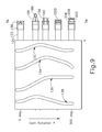
- FIG. 19 depicts a perspective view of the distal end of another exemplary alternative dilator tube that may be readily incorporated in the PETDD of FIG. 1 , in a collapsed state;
- FIG. 20 depicts a side elevational view of the dilator tube of FIG. 19 , in the collapsed state
- FIG. 21 depicts another side elevational view of the dilator tube of FIG. 19 , in the collapsed state, rotated 90 degrees about the longitudinal axis of the dilator tube from the position shown in FIG. 20 ;
- FIG. 22 depicts a distal end view of the dilator tube of FIG. 19 , in the collapsed state
- FIG. 23 depicts a cross-sectional view of the dilator tube of FIG. 19 , taken along line 23 - 23 of FIG. 21 ;
- FIG. 24 depicts a perspective view of the dilator tube of FIG. 23 , in an expanded state
- FIG. 25 depicts a side elevational view of the dilator tube of FIG. 19 , in the expanded state
- FIG. 26 depicts a distal end view of the dilator tube of FIG. 19 , in the expanded state.
- FIG. 27 depicts a cross-sectional view of the dilator tube of FIG. 19 , taken along line 27 - 27 of FIG. 25 .
- a pressure equalization (PE) tube may be delivered to the tympanic membrane (TM) of a patient as a way of treating, for example, otitis media.
- a delivery instrument may be used to insert PE tubes in the tympanic membrane (TM) without the use of general anesthesia.
- FIG. 1 shows an exemplary equalization tube delivery device (PETDD) ( 100 ) that may be used in such procedures. It should be understood that PETDD ( 100 ) may be used with an endoscope to provide visualization of the tympanic membrane (TM) during use of PETDD ( 100 ).
- a patient may receive local anesthesia at the tympanic membrane (TM) through a process of iontophoresis before PETDD ( 100 ) is actuated to deploy a PE tube.
- TM tympanic membrane
- iontophoresis may be provided in accordance with at least some of the teachings of U.S. Pub. No. 2010/0198135, the disclosure of which is incorporated by reference herein; and/or in accordance with at least some of the teachings of U.S. Pat. No. 8,192,420, the disclosure of which is incorporated by reference herein.
- Other suitable ways in which PETDD ( 100 ) may be used will be apparent to those of ordinary skill in the art in view of the teachings herein.
- PETDD ( 100 ) of this example comprises a housing ( 102 ), a rear plate ( 110 ), and a cannula ( 120 ) extending distally from housing ( 102 ).
- Housing ( 102 ) is configured to be handheld, such that an operator may fully operate PETDD ( 100 ) using a single hand.
- Rear plate ( 110 ) includes a vacuum port ( 112 ) and a vent port ( 114 ).
- vacuum port ( 112 ) is in the form of a barbed nib that is configured to couple with a conventional flexible tube; while vent port ( 114 ) is simply an opening formed through rear plate ( 110 ).
- Cannula ( 120 ) of the present example comprises an elongate tube having a clear tip ( 122 ) at the distal end of cannula ( 120 ).
- Clear tip ( 122 ) is configured to contact a patient's tympanic membrane (TM) while enabling visualization of the distal end of cannula ( 120 ).
- rear plate ( 110 ) is hermetically sealed relative to housing ( 102 ). The interface between cannula ( 120 ) and housing ( 102 ) is also hermetically sealed.
- housing ( 102 ) defines a fluid tight hollow interior that is in fluid communication with vacuum port ( 112 ) and an interior region of cannula ( 120 ), where “fluid” in the context of this description includes compressible fluid such as air.
- a chassis ( 104 ) is coupled with housing ( 102 ) and supports several components within housing ( 102 ).
- a second chassis (not shown) is coupled with chassis ( 104 ) and is structurally substantially identical from chassis ( 104 ), but is omitted from FIG. 2 just to enable viewing of features that would otherwise be obscured by the second chassis.
- chassis ( 104 ) supports a camshaft ( 130 ) and a trip mechanism ( 200 ).
- Camshaft ( 130 ) includes a dilator track ( 132 ), a shield tube track ( 134 ), a pusher track ( 136 ), and a piercer track ( 138 ).
- Tracks ( 132 , 134 , 136 , 138 ) are formed as recesses in camshaft ( 130 ) and each track ( 132 , 134 , 136 , 138 ) has a unique configuration in order to provide a particular sequence of operation of translating components as will be described in greater detail below.
- a torsion spring ( 140 ) is coupled to the proximal end of camshaft ( 130 ). Torsion spring ( 140 ) is also grounded against the distal face of rear plate ( 110 ). Torsion spring ( 140 ) resiliently provides a rotational bias to camshaft ( 130 ).
- torsion spring ( 140 ) urges camshaft ( 130 ) to rotate in the clockwise direction (viewed from the distal end of PETDD ( 100 ) toward the proximal end of PETDD ( 100 )) about the longitudinal axis of camshaft ( 130 ).
- trip mechanism selectively resists such rotation. While torsion spring ( 140 ) is used to bias camshaft ( 130 ) in the present example, it should be understood that any other suitable types of components may be used to bias camshaft ( 130 ).
- various components are engaged with camshaft ( 130 ) and are thereby actuated by rotation of camshaft ( 130 ).
- a dilator tube ( 150 ), a shield tube ( 160 ), a pusher tube ( 170 ), and a piercer ( 180 ) are all engaged with camshaft ( 130 ).
- Tubes ( 150 , 160 , 170 ) and piercer ( 180 ) are all coaxially disposed within cannula ( 120 ).
- Piercer ( 180 ) is coaxially and slidably disposed within pusher tube ( 170 ), which is coaxially and slidably disposed within shield tube ( 160 ), which is coaxially and slidably disposed within dilator tube ( 150 ), which is coaxially and slidably disposed within cannula ( 120 ).
- Tubes ( 150 , 160 , 170 ) and piercer ( 180 ) all translate relative to cannula ( 120 ) in a particular sequence in order to deploy a PE tube as will be described in greater detail below. This sequence is driven by rotation of camshaft ( 130 ).
- a cam follower ( 152 ) is fixedly secured to the proximal end of dilator tube ( 150 ).
- Cam follower ( 152 ) includes a laterally projecting pin ( 154 ) that is disposed in dilator track ( 132 ), such that rotation of camshaft ( 130 ) causes cam follower ( 152 ) and dilator tube ( 150 ) to translate.
- a cam follower ( 162 ) is fixedly secured to the proximal end of shield tube ( 160 ).
- Cam follower ( 162 ) includes a laterally projecting pin ( 164 ) that is disposed in shield tube track ( 134 ), such that rotation of camshaft ( 130 ) causes cam follower ( 162 ) and shield tube ( 160 ) to translate.
- a cam follower ( 172 ) is fixedly secured to the proximal end of pusher tube ( 170 ).
- Cam follower ( 172 ) includes a laterally projecting pin ( 174 ) that is disposed in pusher tube track ( 136 ), such that rotation of camshaft ( 130 ) causes cam follower ( 172 ) and pusher tube ( 170 ) to translate.
- a cam follower ( 182 ) is fixedly secured to the proximal end of piercer ( 180 ).
- Cam follower ( 182 ) includes a laterally projecting pin ( 184 ) that is disposed in piercer track ( 138 ), such that rotation of camshaft ( 130 ) causes cam follower ( 182 ) and piercer ( 180 ) to translate.
- the distal end of dilator tube ( 150 ) includes a plurality of generally flexible leaves ( 156 ) that are separated by longitudinally extending gaps ( 158 ). Leaves ( 156 ) are resiliently biased to assume the inwardly deflected positioning shown in FIG. 4 ; but are operable to flex outwardly from this positioning as will be described in greater detail below.
- the distal end of shield tube ( 160 ) simply includes a circular edge ( 166 ).
- the distal end of pusher tube ( 170 ) includes a distal face ( 176 ).
- the difference between the inner diameter of pusher tube ( 170 ) and the outer diameter of pusher tube ( 170 ) is greater than the difference between the inner diameter of shield tube ( 160 ) and the outer diameter of shield tube ( 160 ).
- distal face ( 176 ) presents a more prominent contact surface than circular edge ( 166 ).
- the distal end of piercer ( 180 ) includes a sharp, multi-faceted tip ( 186 ) that is configured to pierce through a patient's tympanic membrane (TM).
- piercer ( 180 ) also includes a neck-down region ( 188 ) having a reduced diameter.
- FIG. 8 shows the positioning of tubes ( 150 , 160 , 170 ), piercer ( 180 ), and PE tube ( 1200 ) within cannula ( 120 ) before camshaft ( 130 ) starts rotating from a home position.
- tip ( 186 ) of piercer ( 180 ) is positioned distal to leaves ( 156 ) of dilator tube ( 150 ), such that leaves ( 156 ) are positioned about neck-down region ( 188 ) of piercer ( 180 ).
- PE tube ( 1200 ) is positioned within the distal end of shield tube ( 160 ), whose distal edge ( 166 ) is just proximal to leaves ( 156 ).
- Pusher tube ( 170 ) is proximal to PE tube ( 1200 ), with distal face ( 176 ) of pusher tube ( 170 ) abutting the proximal end of PE tube ( 1200 ).
- PE tube ( 1200 ) is resiliently biased to assume a rivet-like shape presenting a distal flange ( 1208 ) and a proximal flange ( 1206 ) (see FIG. 13 ).
- PE tube ( 1200 ) is compressed against this bias, thereby assuming a generally cylindraceous configuration, when PE tube ( 1200 ) is disposed within shield tube ( 160 ) as shown in FIG. 8 .
- FIG. 9 depicts a sequence of operation that occurs upon rotation of camshaft ( 130 ) from a home position to an actuated position, where tracks ( 132 , 134 , 136 , 138 ) are shown developed into a flat pattern for purpose of illustration.
- the sequence starts at the top region of FIG. 9 , which shows the distal end of clear tip ( 122 ) contacting the patient's tympanic membrane (TM).
- tubes ( 150 , 160 , 170 ), piercer ( 180 ), and PE tube ( 1200 ) are at the positions shown in FIG. 8 .
- camshaft ( 130 ) starts rotating at the urging of torsion spring ( 140 ), pins ( 154 , 164 , 174 , 184 ) begin to ride along their respective tracks ( 132 , 134 , 136 , 138 ), such that piercer tip ( 186 ) and leaves ( 156 ) are driven distally through the tympanic membrane (TM).
- tubes ( 160 , 170 , 190 ) are also driven distally during this transition, though tubes ( 160 , 170 , 190 ) remain proximal to clear tip ( 122 ) at this stage.
- piercer ( 180 ) begins retracting proximally while tubes ( 160 , 170 , 190 ) continue to advance distally. As shown, shield tube ( 160 ) spreads leaves ( 156 ) outwardly from their default positions. This further dilates the puncture site in the tympanic membrane (TM). Shield tube ( 160 ) continues to contain PE tube ( 1200 ) at this stage. As camshaft ( 130 ) continues to rotate, piercer ( 180 ) and dilator ( 150 ) retract proximally behind clear tip ( 122 ). Shield tube ( 160 ) also begins to retract proximally, while pusher tube ( 170 ) remains longitudinally stationary.
- This relative movement uncovers the proximal end of PE tube ( 1200 ), such that the resilient bias of PE tube ( 1200 ) is allowed to form proximal flange ( 194 ) on the near side of the tympanic membrane (TM).
- cannula ( 120 ) is withdrawn from the patient's ear, leaving the actuated PE tube ( 1200 ) in place in the patient's the tympanic membrane (TM).
- Flanges ( 192 , 194 ) maintain the position of PE tube ( 1200 ) in TM, while the passageway formed by the interior ( 196 ) of PE tube ( 1200 ) (see FIG. 8 ) provides a path for fluid communication between the patient's inner ear and outer ear. This fluid path further provides pressure equalization between the patient's inner ear and outer ear.
- PETDD ( 100 ) of the present example includes a vacuum port ( 112 ) that is operable to couple with a vacuum source (not shown). As also noted above, this vacuum port ( 112 ) is in fluid communication with the interior of housing ( 102 ), which is further in fluid communication with cannula ( 120 ). It should be understood that cannula ( 120 ) and/or one of the tubes ( 150 , 160 , 170 ) within cannula ( 120 ) may provide a path for fluid communication between the interior of housing ( 102 ) and tip ( 122 ). By way of example only, such a path may be formed by a gap between the outer diameter of dilator tube ( 150 ) and the inner diameter of cannula ( 120 ).
- such a path may be formed through the interior of pusher tube ( 170 ), through interior ( 196 ) of PE tube ( 1200 ), and through gaps ( 158 ) between leaves ( 156 ) of dilator ( 150 ).
- Other suitable ways for providing a path for fluid communication between the interior of housing ( 102 ) and tip ( 122 ) will be apparent to those of ordinary skill in the art in view of the teachings herein. Regardless of how the path is formed, it should be understood that the path may be used to communicate a vacuum to tip ( 122 ), which may assist in drawing the tympanic membrane (TM) toward tip ( 122 ).
- an operator may make an initial contact between tip ( 122 ) and TM, then activate a vacuum source that is in communication with port ( 112 ) to communicate a vacuum to tip ( 122 ), thereby completing full contact between tip ( 122 ) and the tympanic membrane (TM).
- a vacuum source that is in communication with port ( 112 ) to communicate a vacuum to tip ( 122 ), thereby completing full contact between tip ( 122 ) and the tympanic membrane (TM).
- Such vacuum assisted contact may reduce risks that may be associated with operator error when the operator fails to achieve sufficient contact between tip ( 122 ) and the tympanic membrane (TM).
- PETDD ( 100 ) of the present example includes a trip mechanism ( 200 ) that is configured to selectively resist rotation of camshaft ( 130 ) by torsion spring ( 140 ).
- trip mechanism ( 200 ) of this example comprises an expandable bellows ( 210 ) and a pivoting member ( 220 ).
- Bellows ( 210 ) includes a fluid port ( 212 ) that is coupled with vent port ( 114 ) of rear plate ( 110 ) via a vent tube ( 214 ) (see FIG. 2 ).
- Bellows ( 210 ) is expandable from a compressed configuration ( FIG. 11A ) to an expanded configuration ( FIG. 11B ).
- Pivoting member ( 220 ) includes a lever arm ( 222 ), a catch arm ( 224 ), and a pivot pin ( 226 ). Pivot pin ( 226 ) is pivotally supported by chassis ( 104 ) and defines a pivot axis ( 228 ). Lever arm ( 222 ) is positioned underneath bellows ( 210 ). Catch arm ( 224 ) is configured to selectively engage a catch feature ( 131 ) of camshaft ( 130 ). In particular, when pivoting member ( 220 ) is in a first position as shown in FIG. 11A , catch arm ( 224 ) is engaged with catch feature ( 131 ) of camshaft ( 130 ).
- This engagement presents camshaft ( 130 ) from rotating under the influence of torsion spring ( 140 ).
- pivoting member ( 220 ) is in a second position as shown in FIG. 11B
- catch arm ( 224 ) is disengaged from catch feature ( 131 ) of camshaft ( 130 ), enabling camshaft ( 130 ) to rotate under the influence of torsion spring ( 140 ) to provide the sequence of operation described above.
- Trip mechanism ( 200 ) of the present example automatically transitions from a first position ( FIG. 11A ) to a second position ( FIG. 11B ) when a certain level of vacuum is achieved within the interior of housing ( 102 ).
- tip ( 122 ) is positioned adjacent to a patient's tympanic membrane (TM) and then a vacuum source communicates a vacuum to tip ( 122 ) via port ( 112 ), the interior of housing ( 102 ), and components between housing ( 102 ) and tip ( 122 ). Before tip ( 122 ) reaches full contact with TM, the pressure within the interior of housing ( 102 ) may reduce slightly.
- a vacuum may be used to assist in achieving full apposition between tip ( 122 ) of cannula ( 120 ) and TM; and that once such apposition is achieved, trip mechanism ( 200 ) may effectively unlock camshaft ( 130 ) to thereby automatically trigger a PE tube ( 1200 ) deployment sequence.
- housing ( 102 ) also includes one or more lateral vent ports ( 106 ) that are positioned to be selectively covered or otherwise closed by the hand of the operator that is grasping housing ( 102 ). While FIG. 1 shows a single vent port ( 106 ), it should be understood that one or more additional vent ports ( 106 ) may be provided. In versions having a user actuated vent port ( 106 ), vent port ( 106 ) may act as a manual switch, providing an additional means for the operator to control actuation of PETDD ( 100 ). In particular, when a vacuum is communicated to vacuum port ( 112 ), such a vacuum may be essentially ineffective until the operator manually covers or otherwise closes vent port ( 106 ).
- the vacuum may simply draw atmospheric air into an open vent port ( 106 ). Once the operator covers or otherwise closes vent port ( 106 ), the vacuum within housing ( 102 ) may provide the full apposition of the tympanic membrane (TM) against tip ( 122 ) and may provide the pressure differential that expands bellows ( 210 ) for actuation of trip mechanism ( 200 ). Regardless of whether a vent port ( 106 ) is provided, it should be understood that a hand switch, foot switch, and/or other type of user input may be interposed between a vacuum source and vacuum port ( 112 ) to provide the operator with further control of vacuum.
- vent port ( 106 ) may provide a greater stability and a reduced risk of inadvertent repositioning of PETDD ( 100 ) through operator error at the time of actuation.
- FIG. 12 shows a merely exemplary alternative pneumatic configuration for PETDD ( 100 ).
- vacuum port ( 112 ) is directly coupled with a vacuum source ( 250 ) via a conduit ( 252 ).
- Vent port ( 114 ) is directly coupled with a valve assembly ( 260 ) via a conduit ( 254 ).
- Valve assembly ( 260 ) provides one fluid path leading to vacuum source ( 250 ) via a conduit ( 262 ); and another fluid path leading to a vent port ( 264 ).
- a valve ( 266 ) within valve assembly ( 260 ) selectively couples conduit ( 254 ) with either conduit ( 262 ) or vent port ( 264 ).
- valve ( 266 ) may initially couple conduit ( 254 ) with conduit ( 262 ), such that the interior of housing ( 102 ) and the interior of bellows ( 210 ) receive the same vacuum simultaneously.
- bellows ( 210 ) remains compressed even when tip ( 122 ) achieves full apposition with the tympanic membrane (TM) since bellows ( 210 ) is not experiencing a pressure differential when valve ( 266 ) is positioned to couple conduit ( 254 ) with conduit ( 262 ).
- valve ( 266 ) may switch valve ( 266 ) to couple conduit ( 254 ) with port ( 114 ), thereby coupling the interior of bellows ( 210 ) with atmospheric air. Since the interior of housing ( 102 ) continues to receive a vacuum, this switching of valve ( 266 ) provides the pressure differential for expansion of bellows ( 210 ), which releases camshaft ( 130 ) for rotation as described above.
- Other suitable arrangements and pneumatic schemes will be apparent to those of ordinary skill in the art in view of the teachings herein.
- FIGS. 13-16 show PE tube ( 1200 ) in greater detail.
- PE tube ( 1200 ) of this example includes a cylindraceous body ( 1202 ) that defines a passageway ( 1204 ).
- a flange ( 1206 ) is located at the proximal end of body ( 1202 ) while a set of petals ( 1208 ) are located at the distal end of body ( 1202 ).
- Flange ( 1206 ) includes a plurality of inwardly directed recesses ( 1207 ). Recesses ( 1207 ) are configured to facilitate flexing of flange ( 1206 ) from an outwardly extended position to a generally cylindraceous position where the material forming flange ( 1206 ) extends longitudinally.
- PE tube ( 1200 ) is formed of a resilient material that is biased to assume the rivet like configuration shown in FIGS. 13-16 .
- flange ( 1206 ) and petals ( 1208 ) may be flexed inwardly toward the longitudinal axis of body ( 1202 ) to provide PE tube ( 1200 ) with a cylindraceous configuration.
- flange ( 1206 ) and petals ( 1208 ) may be flexed such that their outer surfaces are at the same radial distance from the longitudinal axis as the outer perimeter of body ( 1202 ). This radial distance may be slightly less than the radial distance associated with the inner diameter of shield tube ( 160 ), such that PE tube ( 1200 ) may collapse to fit within shield tube ( 160 ).
- PE tube ( 1200 ) When PE tube ( 1200 ) is disposed in a tympanic membrane (TM), petals ( 1208 ) are located medially (i.e., on the middle ear side) while flange ( 1206 ) is located laterally (i.e., on the outer ear side).
- PE tube ( 1200 ) may also be configured in accordance with at least some of the teachings of U.S. patent application Ser. No. 13/800,113, entitled “Tympanic Membrane Pressure Equalization Tube,” filed on Mar. 13, 2013, the disclosure of which is incorporated by reference herein; and/or at least some of the teachings of U.S. patent application Ser. No.
- PE tube ( 1200 ) may take will be apparent to those of ordinary skill in the art in view of the teachings herein.
- dilator tube ( 150 ) and piercer ( 180 ) it may be desirable to consolidate the functionality of dilator tube ( 150 ) and piercer ( 180 ) in a single structure.
- a component within cannula ( 120 ) that is operable to both create a myringotomy incision in the tympanic membrane (TM) like piercer ( 180 ) and expand the myringotomy incision like dilator tube ( 150 ).
- TM tympanic membrane
- Such a component may be expandable in response to distal advancement of shield tube ( 160 ), similar to dilator tube ( 150 ).
- Such a component may also be driven by a cam follower like cam follower ( 152 ).
- dilator tube ( 150 ) that are operable to both create a myringotomy incision in the tympanic membrane (TM) like piercer ( 180 ) and expand the myringotomy incision like dilator tube ( 150 ).
- dilator tube ( 150 ) may also be readily incorporated into a variety of other PETDDs.
- the variations of dilator tube ( 150 ) discussed below may be readily incorporated in any of the PETDDs disclosed in U.S. Pub. No. 2010/0198135, the disclosure of which is incorporated by reference herein.
- the variations of dilator tube ( 150 ) discussed below may be readily incorporated into any of the PETDDs disclosed in U.S. patent application Ser. No. 13/800,113, entitled “Tympanic Membrane Pressure Equalization Tube,” filed on Mar.
- FIGS. 17-18 show an exemplary alternative dilator tube ( 300 ) that may be used in place of both dilator tube ( 150 ) and piercer ( 180 ) described above.
- dilator tube ( 300 ) may be secured to cam follower ( 152 ) as a substitute for dilator tube ( 150 ).
- piercer ( 180 ) and cam follower ( 182 ) may simply be omitted from versions of a PETDD ( 100 ) that has dilator tube ( 300 ).
- Dilator tube ( 300 ) of the present example comprises a tubular portion ( 302 ) and two leaves ( 310 , 320 ).
- Leaf ( 310 ) is joined to tubular portion ( 302 ) by a living hinge ( 312 ).
- Leaf ( 320 ) is also joined to tubular portion ( 302 ) by a living hinge ( 322 ).
- a pair of longitudinally extending gaps ( 330 ) are defined between leaves ( 310 , 320 ). These gaps ( 330 ) include rounded regions near hinges ( 312 , 322 ).
- leaves ( 310 , 320 ) present a duckbill configuration when dilator ( 300 ) is in a collapsed state.
- Leaves ( 310 , 320 ) are resiliently biased to assume the collapsed, inwardly deflected positioning shown in FIG. 17 . However, leaves ( 310 , 320 ) may flex at hinges ( 312 , 322 ) and thereby deflect outwardly to the positions shown in FIG. 18 , such that leaves ( 310 , 320 ) align along the cylindraceous path defined by tubular portion ( 302 ). In particular, as shield tube ( 160 ) is advanced distally through the interior of tubular portion ( 302 ), the distal end of shield tube ( 160 ) drives leaves ( 312 , 322 ) outwardly to the position shown in FIG. 18 .
- the distal edge ( 314 ) of leaf ( 310 ) is generally round. However, the distal edge of leaf ( 320 ) includes a sharp point ( 324 ). Sharp point ( 324 ) projects distally relative to distal edge ( 314 ), such that dilator tube ( 300 ) leads with sharp point ( 324 ). It should be understood that, as dilator tube ( 300 ) is driven into the tympanic membrane (TM), sharp point ( 324 ) will pierce the tympanic membrane (TM) and thereby create a myringotomy incision like piercer ( 180 ) would create. In some instances, the incision created by sharp point ( 324 ) is in the form of a substantially straight line.
- leaves ( 310 , 320 ) may be held in place within the incision while shield tube ( 160 ) is advanced distally through the interior of tubular portion ( 302 ), eventually driving leaves ( 310 , 320 ) outwardly within the incision to dilate the incision.
- Dilator tube ( 300 ) and shield tube ( 160 ) may then be retracted proximally while pusher tube ( 170 ) remains longitudinally stationary, resulting in deployment of PE tube ( 1200 ) in the tympanic membrane (TM) as described above.
- piercer ( 180 ) in the present example provides a more open fluid path within the lumen of pusher tube ( 170 ).
- pusher tube is now more effective at providing fluid communication to the distal end of cannula ( 120 ).
- this larger fluid path may more effectively communicate suction to the distal end of cannula ( 120 ) in versions where PETDD ( 100 ) is coupled with a vacuum source.
- suction may be used to assist in drawing the tympanic membrane (TM) against tip ( 122 ) to improve apposition between the tympanic membrane (TM) and tip ( 122 ).
- suction may be used to remove fluid from the middle ear, and the larger fluid path provided by the elimination of piercer ( 180 ) may facilitate communication of the fluid proximally through the lumen of pusher tube ( 170 ).
- This suction of fluid may be performed after PE tube ( 1200 ) is deployed in the tympanic membrane (TM), with the fluid being drawn through passageway ( 1204 ) of the deployed PE tube ( 1200 ) and tip ( 122 ).
- PETDD ( 100 ) may be used to suction fluid from the middle ear immediately after deployment of PE tube ( 1200 ), instead of having to use a separate suction instrument.
- FIGS. 19-27 show another exemplary alternative dilator tube ( 400 ) that may be used in place of both dilator tube ( 150 ) and piercer ( 180 ) described above.
- dilator tube ( 400 ) may be secured to cam follower ( 152 ) as a substitute for dilator tube ( 150 ).
- piercer ( 180 ) and cam follower ( 182 ) may simply be omitted from versions of a PETDD ( 100 ) that has dilator tube ( 400 ).
- Dilator tube ( 400 ) of the present example comprises a tubular portion ( 402 ) and four leaves ( 410 , 430 , 450 , 470 ).
- Leaf ( 410 ) is joined to tubular portion ( 402 ) by a living hinge ( 412 ).
- Leaf ( 430 ) is joined to tubular portion ( 402 ) by a living hinge ( 432 ).
- Leaf ( 450 ) is joined to tubular portion ( 402 ) by a living hinge ( 452 ).
- Leaf ( 470 ) is joined to tubular portion ( 402 ) by a living hinge ( 472 ).
- Longitudinally extending gaps ( 420 , 440 , 460 , 480 ) are defined between leaves ( 410 , 430 , 450 , 470 ).
- gaps ( 420 , 440 , 460 , 480 ) include rounded regions near hinges ( 412 , 432 , 452 , 472 ). As can be seen in FIGS. 19-22 , the distal ends of leaves ( 410 , 430 , 450 , 470 ) converge when dilator ( 400 ) is in a collapsed state.
- Leaves ( 410 , 430 , 450 , 470 ) are resiliently biased to assume the collapsed, inwardly deflected positioning shown in FIGS. 19-23 .
- leaves ( 410 , 430 , 450 , 470 ) may flex at hinges ( 412 , 432 , 452 , 472 ) and thereby deflect outwardly to the positions shown in FIGS. 24-27 , such that leaves ( 410 , 430 , 450 , 470 ) align along the cylindraceous path defined by tubular portion ( 402 ).
- shield tube ( 160 ) As shield tube ( 160 ) is advanced distally through the interior of tubular portion ( 402 ), the distal end of shield tube ( 160 ) drives leaves ( 410 , 430 , 450 , 470 ) outwardly to the position shown in FIGS. 24-27 .
- Leaves ( 410 , 450 ) are on diametrically opposed sides of tubular portion ( 402 ) and have pointed yet generally blunt distal tips ( 416 , 456 ).
- Leaves ( 430 , 470 ) are on diametrically opposed sides of tubular portion ( 402 ), offset by 90 degrees from leaves ( 410 , 450 ), and have sharp edges ( 434 , 474 ) extending along their respective lengths, with sharp distal tips ( 436 , 476 ). As best seen in FIGS. 22-23 and 26-27 , leaves ( 430 , 470 ) are bent such that sharp edges ( 434 , 474 ) project outwardly.
- each sharp edge ( 434 , 474 ) is formed at the convergence of a curved surface and a radially extending surface of the corresponding leaf ( 430 , 470 ).
- leaves ( 410 , 430 , 450 , 470 ) are driven outwardly to an expanded state as shown in FIGS. 24-27 , the full lengths of sharp edges ( 434 , 474 ) are positioned outside the outer diameter of tubular portion ( 402 ).
- Sharp distal tips ( 436 , 476 ) project distally relative to blunt distal tips ( 416 , 456 ), such that dilator tube ( 400 ) leads with sharp distal tips ( 436 476 ).
- sharp edges ( 434 , 474 ) and sharp distal tips ( 436 , 476 ) may be formed in a laser cutting process.
- initial forms of leaves ( 410 , 430 , 450 , 470 ) may be laser cut from tubular portion ( 402 ).
- an edge of each leaf ( 430 , 470 ) may be bent outwardly.
- the outwardly bent edges may then be laser cut again (e.g., along the same path as a diameter of tubular portion ( 402 )) to form sharp edges ( 434 , 474 ) and sharp distal tips ( 436 , 476 ).
- dilator tube ( 400 ) may include more than two sharpened leaves ( 430 , 470 ), regardless of how many unsharpened leaves ( 410 , 450 ) are provided.
- Sharp edges ( 434 , 474 ) may perform additional cutting of the tympanic membrane (TM) during this dilation step, effectively increasing the length of the incision created by sharp distal tips ( 436 , 476 ).
- Dilator tube ( 400 ) and shield tube ( 160 ) may then be retracted proximally while pusher tube ( 170 ) remains longitudinally stationary, resulting in deployment of PE tube ( 1200 ) in the tympanic membrane (TM) as described above.
- piercer ( 180 ) in the present example provides a more open fluid path within the lumen of pusher tube ( 170 ).
- pusher tube is now more effective at providing fluid communication to the distal end of cannula ( 120 ).
- this larger fluid path may more effectively communicate suction to the distal end of cannula ( 120 ) in versions where PETDD ( 100 ) is coupled with a vacuum source.
- suction may be used to assist in drawing the tympanic membrane (TM) against tip ( 122 ) to improve apposition between the tympanic membrane (TM) and tip ( 122 ).
- suction may be used to remove fluid from the middle ear, and the larger fluid path provided by the elimination of piercer ( 180 ) may facilitate communication of the fluid proximally through the lumen of pusher tube ( 170 ).
- This suction of fluid may be performed after PE tube ( 1200 ) is deployed in the tympanic membrane (TM), with the fluid being drawn through passageway ( 1204 ) of the deployed PE tube ( 1200 ) and tip ( 122 ).
- PETDD ( 100 ) may be used to suction fluid from the middle ear immediately after deployment of PE tube ( 1200 ), instead of having to use a separate suction instrument.
- Versions described above may be designed to be disposed of after a single use, or they can be designed to be used multiple times. Versions may, in either or both cases, be reconditioned for reuse after at least one use. Reconditioning may include any combination of the steps of disassembly of the device, followed by cleaning or replacement of particular pieces, and subsequent reassembly. In particular, some versions of the device may be disassembled, and any number of the particular pieces or parts of the device may be selectively replaced or removed in any combination. Upon cleaning and/or replacement of particular parts, some versions of the device may be reassembled for subsequent use either at a reconditioning facility, or by a user immediately prior to a procedure.
- reconditioning of a device may utilize a variety of techniques for disassembly, cleaning/replacement, and reassembly. Use of such techniques, and the resulting reconditioned device, are all within the scope of the present application.
- versions described herein may be sterilized before and/or after a procedure.
- the device is placed in a closed and sealed container, such as a plastic or TYVEK bag.
- the container and device may then be placed in a field of radiation that can penetrate the container, such as gamma radiation, x-rays, or high-energy electrons.
- the radiation may kill bacteria on the device and in the container.
- the sterilized device may then be stored in the sterile container for later use.
- a device may also be sterilized using any other technique known in the art, including but not limited to beta or gamma radiation, ethylene oxide, or steam.
Landscapes
- Health & Medical Sciences (AREA)
- Life Sciences & Earth Sciences (AREA)
- Surgery (AREA)
- Animal Behavior & Ethology (AREA)
- General Health & Medical Sciences (AREA)
- Engineering & Computer Science (AREA)
- Biomedical Technology (AREA)
- Heart & Thoracic Surgery (AREA)
- Veterinary Medicine (AREA)
- Public Health (AREA)
- Medical Informatics (AREA)
- Pathology (AREA)
- Molecular Biology (AREA)
- Nuclear Medicine, Radiotherapy & Molecular Imaging (AREA)
- Physics & Mathematics (AREA)
- Acoustics & Sound (AREA)
- Biophysics (AREA)
- Otolaryngology (AREA)
- Psychology (AREA)
- Vascular Medicine (AREA)
- External Artificial Organs (AREA)
- Media Introduction/Drainage Providing Device (AREA)
Abstract
Description
Claims (20)
Priority Applications (4)
| Application Number | Priority Date | Filing Date | Title |
|---|---|---|---|
| US13/804,612 US9681891B2 (en) | 2013-03-14 | 2013-03-14 | Tympanostomy tube delivery device with cutting dilator |
| PCT/US2014/018347 WO2014143543A1 (en) | 2013-03-14 | 2014-02-25 | Tympanostomy tube delivery device with cutting dilator |
| EP14709141.7A EP2967643B1 (en) | 2013-03-14 | 2014-02-25 | Tympanostomy tube delivery device with cutting dilator |
| US15/626,756 US10653446B2 (en) | 2013-03-14 | 2017-06-19 | Tympanostomy tube delivery device with cutting dilator |
Applications Claiming Priority (1)
| Application Number | Priority Date | Filing Date | Title |
|---|---|---|---|
| US13/804,612 US9681891B2 (en) | 2013-03-14 | 2013-03-14 | Tympanostomy tube delivery device with cutting dilator |
Related Child Applications (1)
| Application Number | Title | Priority Date | Filing Date |
|---|---|---|---|
| US15/626,756 Continuation US10653446B2 (en) | 2013-03-14 | 2017-06-19 | Tympanostomy tube delivery device with cutting dilator |
Publications (2)
| Publication Number | Publication Date |
|---|---|
| US20140277050A1 US20140277050A1 (en) | 2014-09-18 |
| US9681891B2 true US9681891B2 (en) | 2017-06-20 |
Family
ID=50240086
Family Applications (2)
| Application Number | Title | Priority Date | Filing Date |
|---|---|---|---|
| US13/804,612 Active 2035-10-13 US9681891B2 (en) | 2013-03-14 | 2013-03-14 | Tympanostomy tube delivery device with cutting dilator |
| US15/626,756 Active 2033-10-12 US10653446B2 (en) | 2013-03-14 | 2017-06-19 | Tympanostomy tube delivery device with cutting dilator |
Family Applications After (1)
| Application Number | Title | Priority Date | Filing Date |
|---|---|---|---|
| US15/626,756 Active 2033-10-12 US10653446B2 (en) | 2013-03-14 | 2017-06-19 | Tympanostomy tube delivery device with cutting dilator |
Country Status (3)
| Country | Link |
|---|---|
| US (2) | US9681891B2 (en) |
| EP (1) | EP2967643B1 (en) |
| WO (1) | WO2014143543A1 (en) |
Cited By (15)
| Publication number | Priority date | Publication date | Assignee | Title |
|---|---|---|---|---|
| WO2018027102A1 (en) | 2016-08-05 | 2018-02-08 | Tusker Medical, Inc. | Systems, apparatus, and methods for delivery of therapeutic substance to the middle and/or inner ear |
| US10130515B2 (en) | 2001-04-26 | 2018-11-20 | Tusker Medical, Inc. | Mechanically registered videoscopic myringotomy/tympanostomy tube placement system |
| US10195086B2 (en) | 2014-08-11 | 2019-02-05 | Tusker Medical, Inc. | Tympanostomy tube delivery device with rotatable |
| US10219950B2 (en) | 2013-03-14 | 2019-03-05 | Tusker Medical, Inc. | Features to improve and sense tympanic membrane apposition by tympanostomy tube delivery instrument |
| US10258776B2 (en) | 2007-04-19 | 2019-04-16 | Tusker Medical, Inc. | System and method for treatment of target tissues within the ears |
| WO2019143587A1 (en) | 2018-01-16 | 2019-07-25 | Tusker Medical, Inc. | Visualization devices and methods for otologic procedures |
| WO2019143617A1 (en) | 2018-01-16 | 2019-07-25 | Tusker Medical, Inc. | Earset assembly for providing iontophoresis including valve |
| WO2019152866A1 (en) | 2018-02-02 | 2019-08-08 | Tusker Medical, Inc. | Systems, apparatus, and methods for transport and delivery of therapeutic substance to middle ear |
| US10610412B2 (en) | 2009-07-15 | 2020-04-07 | Tusker Medical, Inc. | Tympanic membrane pressure equalization tube delivery system |
| US10632017B2 (en) | 2009-07-15 | 2020-04-28 | Tusker Medical, Inc. | Trigger assembly for tympanostomy tube delivery device |
| US10653446B2 (en) | 2013-03-14 | 2020-05-19 | Tusker Medical, Inc. | Tympanostomy tube delivery device with cutting dilator |
| US10653561B2 (en) | 2014-08-12 | 2020-05-19 | Tusker Medical, Inc. | Tympanostomy tube delivery device with replaceable shaft portion |
| US10736785B2 (en) | 2014-08-12 | 2020-08-11 | Tusker Medical, Inc. | Tympanostomy tube delivery device with cutter force clutch |
| US10765560B2 (en) | 2014-08-08 | 2020-09-08 | Tusker Medical, Inc. | Tympanostomy tube delivery device with elastomeric brake |
| WO2021011855A1 (en) | 2019-07-17 | 2021-01-21 | Tusker Medical, Inc. | Systems, devices, and methods for visualization during medical procedures |
Families Citing this family (8)
| Publication number | Priority date | Publication date | Assignee | Title |
|---|---|---|---|---|
| JP6525668B2 (en) * | 2015-03-27 | 2019-06-05 | テルモ株式会社 | Medical device |
| EP3341068A1 (en) * | 2015-08-28 | 2018-07-04 | Heartware, Inc. | Dilation delivery system for a medical device |
| US12390370B2 (en) | 2019-11-01 | 2025-08-19 | Aventamed Designated Activity Company | Tympanostomy tube |
| CN114641266B (en) * | 2019-11-01 | 2025-11-04 | 阿文塔米德指定活动公司 | A tympanic membrane treatment device |
| US11116668B1 (en) | 2020-05-04 | 2021-09-14 | Roger D. Haring | Cross-flange tympanostomy tube |
| US11950768B2 (en) | 2020-10-13 | 2024-04-09 | Baylor College Of Medicine | Radially adjustable surgical dilator for remote access surgical procedures |
| US20230372156A1 (en) * | 2020-10-28 | 2023-11-23 | Smith & Nephew, Inc. | Systems and methods of tympanostomy tube delivery |
| US20240307231A1 (en) * | 2023-03-13 | 2024-09-19 | Ear Tech, LLC | Tympanostomy tube insertion device |
Citations (165)
| Publication number | Priority date | Publication date | Assignee | Title |
|---|---|---|---|---|
| US858673A (en) | 1906-08-30 | 1907-07-02 | Charles R Roswell | Device adapted for curing deafness. |
| US1920006A (en) | 1932-07-26 | 1933-07-25 | Edward A Arnim Jr | Prostatic catheter |
| US2162681A (en) | 1938-06-13 | 1939-06-13 | Henry Lange | Bronchoscope |
| US3473170A (en) | 1967-07-05 | 1969-10-21 | Dow Corning | Middle ear prosthesis |
| US3638643A (en) | 1967-10-17 | 1972-02-01 | Hotchkiss Instr Inc | Endoscope for photographic recording |
| US3741197A (en) | 1970-09-04 | 1973-06-26 | Micromedia Syst Inc | Percussion apparatus for blood sampling |
| US3807404A (en) | 1973-03-12 | 1974-04-30 | Whaledent Inc | Probe unit for electro-surgical device |
| US3888258A (en) | 1972-11-07 | 1975-06-10 | Taichiro Akiyama | Drain for the eardrum and apparatus for introducing the same |
| US3897786A (en) | 1971-02-05 | 1975-08-05 | Richards Mfg Co | Disposable myringotomy apparatus |
| US3913584A (en) | 1974-06-28 | 1975-10-21 | Xomox Corp | Combination myringotomy scalpel, aspirator and otological vent tube inserter |
| US3948271A (en) | 1972-11-07 | 1976-04-06 | Taichiro Akiyama | Drain for the eardrum and apparatus for introducing the same |
| US3991755A (en) | 1973-07-27 | 1976-11-16 | Medicon, Inc. | Iontophoresis apparatus for applying local anesthetics |
| US4168697A (en) | 1977-01-17 | 1979-09-25 | Cantekin Erdem I | Middle ear ventilating tube and method |
| US4335715A (en) | 1980-06-20 | 1982-06-22 | Kirkley William H | Osteotomy guide |
| US4335713A (en) | 1979-02-20 | 1982-06-22 | Olympus Optical Co., Ltd. | Otoscope |
| US4380998A (en) | 1981-01-05 | 1983-04-26 | Welch Allyn, Inc. | Soft tip speculum |
| FR2526656A1 (en) | 1982-05-12 | 1983-11-18 | Dumas Yves | Ear syringe using recycled water - has flexible vessel collecting water from bowl shaped to fit patient's ear |
| US4468218A (en) | 1982-09-24 | 1984-08-28 | Armstrong Beverly W | Ventilation tube for the middle ear and method of implanting same |
| US4473073A (en) | 1982-01-20 | 1984-09-25 | Microtek Medical Incorporated | Myringotomy tube inserter and method for inserting myringotomy tubes |
| US4564009A (en) | 1983-08-24 | 1986-01-14 | Mine Safety Appliances Company | Universal ear plug |
| CN86105171A (en) | 1985-08-21 | 1987-03-04 | 明尼苏达州采矿制造公司 | Electrode close to tympanic membrane and method for stimulating and recording signals |
| US4712537A (en) | 1986-08-13 | 1987-12-15 | Pender Daniel J | Apparatus for treating recurrent ear infections |
| US4796624A (en) | 1986-11-19 | 1989-01-10 | Concept, Inc. | Lashliner |
| US4800876A (en) | 1981-12-11 | 1989-01-31 | Fox Kenneth R | Method of and apparatus for laser treatment of body lumens |
| US4913132A (en) | 1986-07-25 | 1990-04-03 | Noble Gabriel | Myringotomy instrument |
| US4946440A (en) | 1988-10-05 | 1990-08-07 | Hall John E | Evertible membrane catheter and method of use |
| US4968296A (en) | 1989-12-20 | 1990-11-06 | Robert Ritch | Transscleral drainage implant device for the treatment of glaucoma |
| US4971076A (en) | 1987-09-25 | 1990-11-20 | Barbara Densert | Method of ventilating the middle ear by means of a ventilation tube which can be applied in the tympanic membrane |
| US5026378A (en) | 1989-11-09 | 1991-06-25 | Goldsmith Iii Manning M | Punch myringotomy system and method |
| US5044373A (en) | 1989-02-01 | 1991-09-03 | Gn Danavox A/S | Method and apparatus for fitting of a hearing aid and associated probe with distance measuring means |
| US5047007A (en) | 1989-12-22 | 1991-09-10 | Medtronic, Inc. | Method and apparatus for pulsed iontophoretic drug delivery |
| US5053040A (en) | 1989-11-09 | 1991-10-01 | Goldsmith Iii Manning M | Method of performing a myringotomy |
| US5092837A (en) | 1989-12-20 | 1992-03-03 | Robert Ritch | Method for the treatment of glaucoma |
| US5107861A (en) | 1990-12-10 | 1992-04-28 | Lillian Narboni | Safe ear clean button and protection with attachment device |
| US5135478A (en) | 1989-05-10 | 1992-08-04 | Drug Delivery Systems Inc. | Multi-signal electrical transdermal drug applicator |
| US5178623A (en) | 1992-02-11 | 1993-01-12 | Cinberg James Z | Tympanic ventilation tube, applicator, and related technique |
| US5254120A (en) | 1992-02-11 | 1993-10-19 | Cinberg James Z | Myringotomy ventilliation tube, method, applicator and kit |
| US5261903A (en) | 1988-04-11 | 1993-11-16 | M.D. Inc. | Composite anesthetic article and method of use |
| USD352780S (en) | 1993-04-19 | 1994-11-22 | Valleylab Inc. | Combined suction, irrigation and electrosurgical handle |
| US5370656A (en) | 1993-02-26 | 1994-12-06 | Merocel Corporation | Throat pack |
| JPH07116190A (en) | 1993-10-21 | 1995-05-09 | Nagashima Ika Kikai Kk | Eardrum anesthesia machine and treatment machine |
| US5421818A (en) | 1993-10-18 | 1995-06-06 | Inner Ear Medical Delivery Systems, Inc. | Multi-functional inner ear treatment and diagnostic system |
| US5466239A (en) | 1992-07-28 | 1995-11-14 | Cinberg; James Z. | Myringotomy ventilation tube and associated method |
| US5489286A (en) | 1992-07-28 | 1996-02-06 | Cinberg; James Z. | Antibiotic impregnated myringotomy ventilation tube |
| US5496329A (en) | 1993-09-08 | 1996-03-05 | Alpha Surgical, Inc. | Method and apparatus for implanting a medical ventilation tube |
| US5610988A (en) | 1993-09-08 | 1997-03-11 | Sony Corporation | Hearing aid set |
| USD378611S (en) | 1995-10-19 | 1997-03-25 | Ethicon Endo-Surgery, Inc. | Electrosurgical instrument |
| US5643280A (en) | 1995-12-07 | 1997-07-01 | The Anspach Effort, Inc. | Integral myringotomy tube and inserter |
| US5645584A (en) | 1996-02-21 | 1997-07-08 | Suyama Dental Laboratory Inc. | Tympanostomy tube and method for producing the same |
| US5658235A (en) | 1995-03-31 | 1997-08-19 | Medrx, Inc. | Video otoscope and optical lens system therefor |
| US5674196A (en) | 1996-01-05 | 1997-10-07 | Donaldson; John | Device for introducing medical fluid into the human ear |
| US5676635A (en) | 1995-08-30 | 1997-10-14 | Levin; Bruce | Instrument for insertion of an endotracheal tube |
| US5681323A (en) | 1996-07-15 | 1997-10-28 | Arick; Daniel S. | Emergency cricothyrotomy tube insertion |
| DE19618585A1 (en) | 1996-05-09 | 1997-11-13 | Michael Glimmann | Ear plug for tinnitus treatment |
| USD387863S (en) | 1996-07-22 | 1997-12-16 | Microvena Corporation | Medical device delivery handle |
| US5707383A (en) | 1995-10-05 | 1998-01-13 | Xomed Surgical Products, Inc. | Method of removing soft tissue in the middle ear |
| US5775336A (en) | 1996-05-31 | 1998-07-07 | Georgetown University | Tubular medical device |
| US5782744A (en) | 1995-11-13 | 1998-07-21 | Money; David | Implantable microphone for cochlear implants and the like |
| US5792100A (en) | 1995-05-19 | 1998-08-11 | Shantha; T. R. | Treatment method for transsphenoidal stimulation of the pituitary gland and of nerve structures |
| WO1999011175A1 (en) | 1997-08-29 | 1999-03-11 | Jonathon Sillman | Speculum for simultaneously viewing and removing obstructions |
| US5893828A (en) | 1996-05-02 | 1999-04-13 | Uram; Martin | Contact laser surgical endoscope and associated myringotomy procedure |
| US5893837A (en) | 1997-02-28 | 1999-04-13 | Staar Surgical Company, Inc. | Glaucoma drain implanting device and method |
| US5984930A (en) | 1996-09-30 | 1999-11-16 | George S. Allen | Biopsy guide |
| USD418223S (en) | 1998-06-05 | 1999-12-28 | Eclipse Surgical Technologies, Inc. | Hand piece for surgical and biopsy procedures |
| US6022342A (en) | 1998-06-02 | 2000-02-08 | Mukherjee; Dipankar | Catheter introducer for antegrade and retrograde medical procedures |
| USD420741S (en) | 1996-08-20 | 2000-02-15 | Ethicon Endo-Surgery, Inc. | Handle for an electrosurgical instrument |
| US6024726A (en) | 1998-08-25 | 2000-02-15 | Hill; Frank C | Middle ear fluid aspirator |
| US6039748A (en) | 1997-08-05 | 2000-03-21 | Femrx, Inc. | Disposable laparoscopic morcellator |
| US6045528A (en) | 1997-06-13 | 2000-04-04 | Intraear, Inc. | Inner ear fluid transfer and diagnostic system |
| USD424197S (en) | 1999-02-12 | 2000-05-02 | Thermolase Corporation | Laser handpiece housing |
| US6059803A (en) | 1999-06-01 | 2000-05-09 | Spilman; Daniel A. | Ear vacuum |
| USD426135S (en) | 1999-09-02 | 2000-06-06 | Shu-Chen Lee | Tool handle |
| US6077179A (en) * | 1998-05-21 | 2000-06-20 | Liechty, Ii; Victor Jay | Arrowhead with a tip having convex facets |
| US6110196A (en) | 1998-06-17 | 2000-08-29 | Edwards; Stuart D. | Apparatus and method for tympanic membrane tightening |
| US6137889A (en) | 1998-05-27 | 2000-10-24 | Insonus Medical, Inc. | Direct tympanic membrane excitation via vibrationally conductive assembly |
| DE19918288A1 (en) | 1999-04-22 | 2000-10-26 | Braun Gmbh | Ear reflectometer; has measuring point to fit in ear canal and device to observe ear canal, which includes light conductor coupled between lens at measuring point and eye piece or viewing device |
| US6171236B1 (en) | 1990-03-02 | 2001-01-09 | General Surgical Innovations, Inc. | Method of retracting soft tissue from a bone |
| US6183469B1 (en) | 1997-08-27 | 2001-02-06 | Arthrocare Corporation | Electrosurgical systems and methods for the removal of pacemaker leads |
| US6200280B1 (en) | 1998-05-29 | 2001-03-13 | Theracardia, Inc. | Cardiac massage apparatus and method |
| US6206888B1 (en) | 1997-10-01 | 2001-03-27 | Scimed Life Systems, Inc. | Stent delivery system using shape memory retraction |
| US6245077B1 (en) | 2000-01-21 | 2001-06-12 | Exmoor Plastics Ltd. | Universal myringotomy tube/aural grommet inserter and methods |
| US6251121B1 (en) | 1996-12-02 | 2001-06-26 | Angiotrax, Inc. | Apparatus and methods for intraoperatively performing surgery |
| US6258067B1 (en) | 1998-12-08 | 2001-07-10 | Smith & Nephew, Inc. | Middle ear fluid aspirator |
| US20010020173A1 (en) | 1999-02-26 | 2001-09-06 | Klumb Katherine J. | Endoluminal prosthesis placing method |
| USD450843S1 (en) | 2000-05-30 | 2001-11-20 | Boston Scientific Corporation | Thrombectomy handpiece |
| US20020026125A1 (en) | 2000-08-25 | 2002-02-28 | Hans Leysieffer | Device for electromechanical stimulation and testing of hearing |
| US6358231B1 (en) | 1998-08-24 | 2002-03-19 | Biopolymer, Inc. | Transdermal anesthetizing solution and method and apparatus for anesthetizing the ear canal and tympanic membrane |
| US6398758B1 (en) | 1999-02-16 | 2002-06-04 | Stephen C. Jacobsen | Medicament delivery system |
| US20020069883A1 (en) | 2000-12-08 | 2002-06-13 | Aviv Hirchenbain | Device for active regulation of pressure on outer ear |
| US20020111585A1 (en) | 2001-02-13 | 2002-08-15 | Scimed Life Systems, Inc. | Hemostasis valve |
| US6440102B1 (en) | 1998-07-23 | 2002-08-27 | Durect Corporation | Fluid transfer and diagnostic system for treating the inner ear |
| US6447522B2 (en) | 1998-09-30 | 2002-09-10 | C. R. Bard, Inc. | Implant delivery system |
| US20020138091A1 (en) | 2001-03-23 | 2002-09-26 | Devonrex, Inc. | Micro-invasive nucleotomy device and method |
| US20020161379A1 (en) | 2001-04-26 | 2002-10-31 | Kaplan Aaron V. | Mechanically registered videoscopic myringotomy/tympanostomy tube placement system |
| US6475138B1 (en) | 1995-07-12 | 2002-11-05 | Laser Industries Ltd. | Apparatus and method as preparation for performing a myringotomy in a child's ear without the need for anaesthesia |
| US20020169456A1 (en) | 2001-05-10 | 2002-11-14 | Hosheng Tu | Delivery system for a stentless valve bioprosthesis |
| US20030018291A1 (en) | 1999-12-08 | 2003-01-23 | Hill Frank C. | Ear tube and method of insertion |
| US6512950B2 (en) | 2000-02-18 | 2003-01-28 | University Of Utah Research Foundation | Methods for delivering agents using alternating current |
| US6514261B1 (en) | 1998-09-30 | 2003-02-04 | Impra, Inc. | Delivery mechanism for implantable stent |
| US6522827B1 (en) | 2000-10-11 | 2003-02-18 | Trimedyne, Inc. | Laser devices for performing a myringotomy |
| US20030040717A1 (en) | 2001-08-09 | 2003-02-27 | Becton, Dickinson And Company, A New Jersey Corporation | Retracting needle safety device |
| US20030060799A1 (en) | 2001-09-21 | 2003-03-27 | Arenberg Michael H. | Aural catheter system including anchor balloon and balloon inflation device |
| US6553253B1 (en) | 1999-03-12 | 2003-04-22 | Biophoretic Therapeutic Systems, Llc | Method and system for electrokinetic delivery of a substance |
| US20030187456A1 (en) | 2001-08-03 | 2003-10-02 | Perry Christopher Francis | Ventilation tube for a middle ear |
| US20030199791A1 (en) | 2002-04-19 | 2003-10-23 | Pelikan Technologies, Inc. | Method and apparatus for penetrating tissue |
| US6645173B1 (en) | 2002-03-29 | 2003-11-11 | Barbara Liebowitz | Dripless eardrop applicator |
| US20040054339A1 (en) | 2001-01-26 | 2004-03-18 | Danuta Ciok | Cleansing appliance |
| US20050033343A1 (en) | 2002-11-25 | 2005-02-10 | F.D. Cardio Ltd. | Catheter drive |
| US6916159B2 (en) | 2002-10-09 | 2005-07-12 | Therasense, Inc. | Device and method employing shape memory alloy |
| US20050165368A1 (en) | 2003-11-14 | 2005-07-28 | Daniel Py | Delivery device and method of delivery |
| US20050182385A1 (en) | 2004-01-20 | 2005-08-18 | Epley John M. | Minimally invasive, sustained, intra-tympanic drug delivery system |
| US20050187546A1 (en) | 2001-09-19 | 2005-08-25 | Curon Medical, Inc. | Systems and methods for treating tissue regions of the body |
| US20050235422A1 (en) | 2004-04-09 | 2005-10-27 | Arthur Wallace | Audiovisual distraction in patients undergoing surgery with regional anesthesia |
| US20050240147A1 (en) | 2004-04-21 | 2005-10-27 | Exploramed Ii, Inc. | Devices, systems and methods for diagnosing and treating sinusitus and other disorders of the ears, nose and/or throat |
| US6962595B1 (en) | 2002-01-22 | 2005-11-08 | Cardica, Inc. | Integrated anastomosis system |
| US20060095050A1 (en) | 2004-09-14 | 2006-05-04 | William A. Cook Australia Pty. Ltd. | Large diameter sheath |
| US20060142700A1 (en) | 2003-06-20 | 2006-06-29 | Sobelman Owen S | Two-way slit valve |
| US20060161218A1 (en) | 2003-11-26 | 2006-07-20 | Wicab, Inc. | Systems and methods for treating traumatic brain injury |
| US20060163313A1 (en) | 2005-01-25 | 2006-07-27 | Xorbent Technologies, L.L.C. | Septal stapler apparatus |
| US7127285B2 (en) | 1999-03-12 | 2006-10-24 | Transport Pharmaceuticals Inc. | Systems and methods for electrokinetic delivery of a substance |
| WO2006119512A2 (en) | 2005-05-05 | 2006-11-09 | University Of Virginia Patent Foundation | Surgical tool and insertion device for tube placement |
| US7137975B2 (en) | 2001-02-13 | 2006-11-21 | Aciont, Inc. | Method for increasing the battery life of an alternating current iontophoresis device using a barrier-modifying agent |
| US20060282062A1 (en) | 2005-06-10 | 2006-12-14 | Searete Llc, A Limited Liability Corporation Of The State Of Delaware | Methods and systems for neural maintenance and regeneration |
| USD535027S1 (en) | 2004-10-06 | 2007-01-09 | Sherwood Services Ag | Low profile vessel sealing and cutting mechanism |
| US20070233222A1 (en) | 2006-02-21 | 2007-10-04 | Med Institute, Inc. | Split sheath deployment system |
| US20080027423A1 (en) | 2006-07-25 | 2008-01-31 | Zoom Therapeutics, Inc. | Systems for treatment of nasal tissue |
| US20080051804A1 (en) | 2005-05-05 | 2008-02-28 | Cottler Shayn P | Tube, stent and collar insertion device |
| WO2008030485A2 (en) | 2006-09-07 | 2008-03-13 | Neurosystec Corporation | Catheter for localized drug delivery and/or electrical stimulation |
| US7344507B2 (en) | 2002-04-19 | 2008-03-18 | Pelikan Technologies, Inc. | Method and apparatus for lancet actuation |
| US7381210B2 (en) | 2003-03-14 | 2008-06-03 | Edwards Lifesciences Corporation | Mitral valve repair system and method for use |
| US20080212416A1 (en) | 2006-12-20 | 2008-09-04 | Roland Polonio | Notification device and method for programming a notification device |
| US20080262468A1 (en) | 2007-04-19 | 2008-10-23 | Acclarent, Inc. | System and Method for the Simultaneous Bilateral Treatment of Target Tissues Within the Ears Using a Guide Block Structure |
| WO2009010788A1 (en) | 2007-07-13 | 2009-01-22 | Braun Air Ears Limited | Aural device |
| US20090163828A1 (en) | 2006-05-16 | 2009-06-25 | Board Of Trustees Of Southern Illinois University | Tinnitus Testing Device and Method |
| USD595410S1 (en) | 2007-05-07 | 2009-06-30 | Derma Dream Ltd. | Demabrasion applicator |
| USD598543S1 (en) | 2006-06-13 | 2009-08-18 | Angiomed Gmbh & Co. Medizintechnik Kg | Handle for a medical delivery device |
| US20090209972A1 (en) | 2008-02-20 | 2009-08-20 | Loushin Michael K H | Ventilation Device and Insertion System Therefor |
| US20090299344A1 (en) | 2005-07-20 | 2009-12-03 | Woojin Lee | Surgical instrument guide device |
| US20090299379A1 (en) | 2008-05-28 | 2009-12-03 | Yeshayahu Katz | Myringotomy instrument |
| US20100041447A1 (en) | 2008-08-13 | 2010-02-18 | Will Wang Graylin | Wearable headset with self-contained vocal feedback and vocal command |
| US20100061581A1 (en) | 2008-09-09 | 2010-03-11 | Creative Technology Ltd | Sound producing device |
| US20100198135A1 (en) | 2008-07-31 | 2010-08-05 | Acclarent, Inc. | Systems and methods for anesthetizing ear tissue |
| US20100217296A1 (en) | 2008-12-24 | 2010-08-26 | Acclarent, Inc. | Silent Effusion Removal |
| USD622842S1 (en) | 2009-08-06 | 2010-08-31 | Given Imaging Ltd. | Implantable monitor delivery device handle |
| US20100324488A1 (en) | 2007-02-28 | 2010-12-23 | Smith Robert C | Trocar assembly with obturator and retractable stylet |
| US20110015645A1 (en) | 2009-07-15 | 2011-01-20 | Greg Liu | Tympanic membrane pressure equalization tube delivery system |
| US20110022069A1 (en) | 2009-07-21 | 2011-01-27 | Miroslav Mitusina | Flexible Inner Member Having a Flexible Region Composed of Longitudinally and Rotationally Offset Partial Circumferential Cuts |
| US20110077579A1 (en) | 2005-03-24 | 2011-03-31 | Harrison William V | Cochlear implant with localized fluid transport |
| USD640374S1 (en) | 2010-07-15 | 2011-06-21 | Acclarent, Inc. | Tube delivery device |
| US8192420B2 (en) | 2007-12-20 | 2012-06-05 | Acclarent, Inc. | Iontophoresis methods |
| US20120179187A1 (en) | 2011-01-07 | 2012-07-12 | Preceptis Medical, Inc. | Stabilization system and aspiration device with protected cutting edge |
| US8282648B2 (en) * | 2007-12-19 | 2012-10-09 | Cook Medical Technologies Llc | Bone cement needle |
| US20120265097A1 (en) | 2011-02-22 | 2012-10-18 | Cook Medical Technologies Llc | Total core biopsy device and method of use |
| US20130338678A1 (en) | 2012-06-15 | 2013-12-19 | Preceptis Medical, Inc. | Insertion system for deploying a ventilation device |
| US20140094733A1 (en) | 2012-04-10 | 2014-04-03 | Acclarent, Inc. | Tympanic Membrane Pressure Equalization Tube |
| US20140100584A1 (en) | 2012-10-05 | 2014-04-10 | Gyrus Acmi, Inc. | Ear pressure equalizing tube and insertion device |
| WO2014075949A1 (en) | 2012-11-15 | 2014-05-22 | Cork Institute Of Technology | Tympanostomy tube and insertion device |
| US20140276906A1 (en) | 2013-03-14 | 2014-09-18 | Acclarent, Inc. | Features to improve and sense tympanic membrane apposition by tympanostomy tube delivery instrument |
| WO2014143543A1 (en) | 2013-03-14 | 2014-09-18 | Acclarent, Inc. | Tympanostomy tube delivery device with cutting dilator |
| US20150164695A1 (en) | 2009-07-15 | 2015-06-18 | Acclarent, Inc. | Tympanic membrane pressure equalization tube delivery system |
| US20160038342A1 (en) | 2014-08-11 | 2016-02-11 | Acclarent, Inc. | Tympanostomy tube delivery device with rotatable flexible shaft |
| US20160038341A1 (en) | 2014-08-08 | 2016-02-11 | Acclarent, Inc. | Tympanostomy tube delivery device with elastomeric brake |
| US20160045369A1 (en) | 2014-08-12 | 2016-02-18 | Acclarent, Inc. | Tympanostomy tube delivery device with cutter force clutch |
| US20160045370A1 (en) | 2014-08-12 | 2016-02-18 | Acclarent, Inc. | Tympanostomy tube delivery device with replaceable shaft portion |
| WO2016025309A1 (en) | 2014-08-12 | 2016-02-18 | Acclarent, Inc. | Trigger assembly for tympanostomy tube delivery device |
Family Cites Families (38)
| Publication number | Priority date | Publication date | Assignee | Title |
|---|---|---|---|---|
| US4406282A (en) | 1981-02-20 | 1983-09-27 | Parker Bruce W | Earplug for an underwater diver |
| US4552137A (en) | 1983-08-16 | 1985-11-12 | Strauss Richard H | Earplugs |
| US4750491A (en) | 1984-11-08 | 1988-06-14 | Allergan, Inc. | Trephine and method |
| US5158540A (en) | 1985-12-19 | 1992-10-27 | Leocor, Inc. | Perfusion catheter |
| US4964850A (en) | 1986-05-07 | 1990-10-23 | Vincent Bouton | Method for treating trans-nasal sinus afflictions using a double t-shaped trans-nasal aerator |
| US6554765B1 (en) | 1996-07-15 | 2003-04-29 | East Giant Limited | Hand held, portable camera with adaptable lens system |
| US5810848A (en) | 1996-08-21 | 1998-09-22 | Hayhurst; John O. | Suturing system |
| US6319199B1 (en) | 1998-10-26 | 2001-11-20 | David M. Sheehan | Portable data collection device |
| US6416512B1 (en) | 1999-11-08 | 2002-07-09 | Health Care Technologies, Llc. | Electrosurgical instrument for ear surgery |
| AU2002219499A1 (en) | 2001-01-19 | 2002-07-30 | Framtidartaekni Ehf. | Hand-held digital imaging diagnostic and operational instrument with wireless transmission data of image |
| US7115136B2 (en) | 2001-06-20 | 2006-10-03 | Park Medical Llc | Anastomotic device |
| US20030097178A1 (en) | 2001-10-04 | 2003-05-22 | Joseph Roberson | Length-adjustable ossicular prosthesis |
| US6871085B2 (en) | 2002-09-30 | 2005-03-22 | Medtronic, Inc. | Cardiac vein lead and guide catheter |
| CN2635015Y (en) | 2003-09-09 | 2004-08-25 | 上海澳华光电内窥镜有限公司 | Chain wheel type bent angle driving device |
| US7182729B2 (en) | 2003-09-18 | 2007-02-27 | Stryker Spine | Surgical retractor with removable scissor arms |
| US20050203550A1 (en) | 2004-03-11 | 2005-09-15 | Laufer Michael D. | Surgical fastener |
| JP4418265B2 (en) | 2004-03-15 | 2010-02-17 | オリンパス株式会社 | Endoscopy device for endoscope |
| US20060004323A1 (en) | 2004-04-21 | 2006-01-05 | Exploramed Nc1, Inc. | Apparatus and methods for dilating and modifying ostia of paranasal sinuses and other intranasal or paranasal structures |
| US7590447B2 (en) | 2005-05-09 | 2009-09-15 | Cardiac Pacemakers, Inc. | Pacing system analyzer having three sensing and pacing channels |
| US7789915B2 (en) | 2005-08-31 | 2010-09-07 | Vance Products Incorporated | Stent for implantation |
| CA2630061C (en) | 2005-11-15 | 2015-03-17 | Johns Hopkins University | An active cannula for bio-sensing and surgical intervention |
| EP1973461A2 (en) | 2005-12-16 | 2008-10-01 | Galil Medical Ltd | Apparatus and method for thermal ablation of uterine fibroids |
| JP4682259B2 (en) | 2006-09-08 | 2011-05-11 | エドワーズ ライフサイエンシーズ コーポレイション | Integrated heart valve delivery system |
| US8708210B2 (en) | 2006-10-05 | 2014-04-29 | Covidien Lp | Method and force-limiting handle mechanism for a surgical instrument |
| US20120283563A1 (en) | 2011-05-03 | 2012-11-08 | Moore Kyle P | Biopsy device with manifold alignment feature and tissue sensor |
| FI119531B (en) | 2007-06-29 | 2008-12-15 | Optomed Oy | Creating an image |
| EP2044888B1 (en) | 2007-10-05 | 2016-12-07 | Covidien LP | Articulation mechanism for a surgical instrument |
| US20100274188A1 (en) | 2007-12-20 | 2010-10-28 | Acclarent, Inc. | Method and System for Treating Target Tissue Within the Eustachian Tube |
| WO2010022103A1 (en) | 2008-08-18 | 2010-02-25 | Cianna Medical, Inc. | Brachytherapy apparatus, systems, and methods for using them |
| US20100160819A1 (en) | 2008-12-18 | 2010-06-24 | Parihar Shailendra K | Biopsy Device with Central Thumbwheel |
| WO2012151573A1 (en) | 2010-01-04 | 2012-11-08 | Zyga Technology, Inc. | Sacroiliac fusion system |
| TWI403302B (en) | 2010-06-30 | 2013-08-01 | Three In One Ent Co Ltd | A portable otoscope |
| US20120078244A1 (en) | 2010-09-24 | 2012-03-29 | Worrell Barry C | Control features for articulating surgical device |
| WO2012054934A1 (en) | 2010-10-22 | 2012-04-26 | Olympus Endo Technology America Inc. | Rotate-to-advance catheterization system |
| CN102122067A (en) | 2011-03-17 | 2011-07-13 | 天津市圣威科技发展有限公司 | Hand-held endoscope with liquid substance transmission channel and rotatable display |
| US10154927B2 (en) | 2012-06-14 | 2018-12-18 | Earways Medical Ltd. | Ear wax removal device and methods thereof |
| WO2014028285A1 (en) | 2012-08-13 | 2014-02-20 | The Brigham And Women's Hospital, Inc. | Methods and devices for inserting a needle |
| EP2938394B1 (en) | 2012-12-28 | 2019-03-13 | Advanced Bionics AG | Tip elements for cochlear implants |
-
2013
- 2013-03-14 US US13/804,612 patent/US9681891B2/en active Active
-
2014
- 2014-02-25 WO PCT/US2014/018347 patent/WO2014143543A1/en not_active Ceased
- 2014-02-25 EP EP14709141.7A patent/EP2967643B1/en active Active
-
2017
- 2017-06-19 US US15/626,756 patent/US10653446B2/en active Active
Patent Citations (213)
| Publication number | Priority date | Publication date | Assignee | Title |
|---|---|---|---|---|
| US858673A (en) | 1906-08-30 | 1907-07-02 | Charles R Roswell | Device adapted for curing deafness. |
| US1920006A (en) | 1932-07-26 | 1933-07-25 | Edward A Arnim Jr | Prostatic catheter |
| US2162681A (en) | 1938-06-13 | 1939-06-13 | Henry Lange | Bronchoscope |
| US3473170A (en) | 1967-07-05 | 1969-10-21 | Dow Corning | Middle ear prosthesis |
| US3638643A (en) | 1967-10-17 | 1972-02-01 | Hotchkiss Instr Inc | Endoscope for photographic recording |
| US3741197A (en) | 1970-09-04 | 1973-06-26 | Micromedia Syst Inc | Percussion apparatus for blood sampling |
| US3897786A (en) | 1971-02-05 | 1975-08-05 | Richards Mfg Co | Disposable myringotomy apparatus |
| US3948271A (en) | 1972-11-07 | 1976-04-06 | Taichiro Akiyama | Drain for the eardrum and apparatus for introducing the same |
| US3888258A (en) | 1972-11-07 | 1975-06-10 | Taichiro Akiyama | Drain for the eardrum and apparatus for introducing the same |
| US3807404A (en) | 1973-03-12 | 1974-04-30 | Whaledent Inc | Probe unit for electro-surgical device |
| US3991755A (en) | 1973-07-27 | 1976-11-16 | Medicon, Inc. | Iontophoresis apparatus for applying local anesthetics |
| US3913584A (en) | 1974-06-28 | 1975-10-21 | Xomox Corp | Combination myringotomy scalpel, aspirator and otological vent tube inserter |
| US4168697A (en) | 1977-01-17 | 1979-09-25 | Cantekin Erdem I | Middle ear ventilating tube and method |
| US4335713A (en) | 1979-02-20 | 1982-06-22 | Olympus Optical Co., Ltd. | Otoscope |
| US4335715A (en) | 1980-06-20 | 1982-06-22 | Kirkley William H | Osteotomy guide |
| US4380998A (en) | 1981-01-05 | 1983-04-26 | Welch Allyn, Inc. | Soft tip speculum |
| US4800876A (en) | 1981-12-11 | 1989-01-31 | Fox Kenneth R | Method of and apparatus for laser treatment of body lumens |
| US4800876B1 (en) | 1981-12-11 | 1991-07-09 | R Fox Kenneth | |
| US4473073A (en) | 1982-01-20 | 1984-09-25 | Microtek Medical Incorporated | Myringotomy tube inserter and method for inserting myringotomy tubes |
| FR2526656A1 (en) | 1982-05-12 | 1983-11-18 | Dumas Yves | Ear syringe using recycled water - has flexible vessel collecting water from bowl shaped to fit patient's ear |
| US4468218A (en) | 1982-09-24 | 1984-08-28 | Armstrong Beverly W | Ventilation tube for the middle ear and method of implanting same |
| US4564009A (en) | 1983-08-24 | 1986-01-14 | Mine Safety Appliances Company | Universal ear plug |
| CN86105171A (en) | 1985-08-21 | 1987-03-04 | 明尼苏达州采矿制造公司 | Electrode close to tympanic membrane and method for stimulating and recording signals |
| EP0214527A1 (en) | 1985-08-21 | 1987-03-18 | Minnesota Mining And Manufacturing Company | External ear canal electrode to be placed proximate the tympanic membrane |
| US4913132A (en) | 1986-07-25 | 1990-04-03 | Noble Gabriel | Myringotomy instrument |
| US4712537A (en) | 1986-08-13 | 1987-12-15 | Pender Daniel J | Apparatus for treating recurrent ear infections |
| US4796624A (en) | 1986-11-19 | 1989-01-10 | Concept, Inc. | Lashliner |
| US4971076A (en) | 1987-09-25 | 1990-11-20 | Barbara Densert | Method of ventilating the middle ear by means of a ventilation tube which can be applied in the tympanic membrane |
| US5261903A (en) | 1988-04-11 | 1993-11-16 | M.D. Inc. | Composite anesthetic article and method of use |
| US4946440A (en) | 1988-10-05 | 1990-08-07 | Hall John E | Evertible membrane catheter and method of use |
| US5044373A (en) | 1989-02-01 | 1991-09-03 | Gn Danavox A/S | Method and apparatus for fitting of a hearing aid and associated probe with distance measuring means |
| US5135478A (en) | 1989-05-10 | 1992-08-04 | Drug Delivery Systems Inc. | Multi-signal electrical transdermal drug applicator |
| US5026378A (en) | 1989-11-09 | 1991-06-25 | Goldsmith Iii Manning M | Punch myringotomy system and method |
| US5053040A (en) | 1989-11-09 | 1991-10-01 | Goldsmith Iii Manning M | Method of performing a myringotomy |
| US5092837A (en) | 1989-12-20 | 1992-03-03 | Robert Ritch | Method for the treatment of glaucoma |
| US4968296A (en) | 1989-12-20 | 1990-11-06 | Robert Ritch | Transscleral drainage implant device for the treatment of glaucoma |
| US5047007A (en) | 1989-12-22 | 1991-09-10 | Medtronic, Inc. | Method and apparatus for pulsed iontophoretic drug delivery |
| US6171236B1 (en) | 1990-03-02 | 2001-01-09 | General Surgical Innovations, Inc. | Method of retracting soft tissue from a bone |
| US5107861A (en) | 1990-12-10 | 1992-04-28 | Lillian Narboni | Safe ear clean button and protection with attachment device |
| US5178623A (en) | 1992-02-11 | 1993-01-12 | Cinberg James Z | Tympanic ventilation tube, applicator, and related technique |
| US5254120A (en) | 1992-02-11 | 1993-10-19 | Cinberg James Z | Myringotomy ventilliation tube, method, applicator and kit |
| US5466239A (en) | 1992-07-28 | 1995-11-14 | Cinberg; James Z. | Myringotomy ventilation tube and associated method |
| US5489286A (en) | 1992-07-28 | 1996-02-06 | Cinberg; James Z. | Antibiotic impregnated myringotomy ventilation tube |
| US5370656A (en) | 1993-02-26 | 1994-12-06 | Merocel Corporation | Throat pack |
| USD352780S (en) | 1993-04-19 | 1994-11-22 | Valleylab Inc. | Combined suction, irrigation and electrosurgical handle |
| US5496329A (en) | 1993-09-08 | 1996-03-05 | Alpha Surgical, Inc. | Method and apparatus for implanting a medical ventilation tube |
| US5610988A (en) | 1993-09-08 | 1997-03-11 | Sony Corporation | Hearing aid set |
| US5421818A (en) | 1993-10-18 | 1995-06-06 | Inner Ear Medical Delivery Systems, Inc. | Multi-functional inner ear treatment and diagnostic system |
| JPH07116190A (en) | 1993-10-21 | 1995-05-09 | Nagashima Ika Kikai Kk | Eardrum anesthesia machine and treatment machine |
| US5658235A (en) | 1995-03-31 | 1997-08-19 | Medrx, Inc. | Video otoscope and optical lens system therefor |
| US5792100A (en) | 1995-05-19 | 1998-08-11 | Shantha; T. R. | Treatment method for transsphenoidal stimulation of the pituitary gland and of nerve structures |
| US6475138B1 (en) | 1995-07-12 | 2002-11-05 | Laser Industries Ltd. | Apparatus and method as preparation for performing a myringotomy in a child's ear without the need for anaesthesia |
| US5676635A (en) | 1995-08-30 | 1997-10-14 | Levin; Bruce | Instrument for insertion of an endotracheal tube |
| US5707383A (en) | 1995-10-05 | 1998-01-13 | Xomed Surgical Products, Inc. | Method of removing soft tissue in the middle ear |
| USD378611S (en) | 1995-10-19 | 1997-03-25 | Ethicon Endo-Surgery, Inc. | Electrosurgical instrument |
| US5782744A (en) | 1995-11-13 | 1998-07-21 | Money; David | Implantable microphone for cochlear implants and the like |
| US5643280A (en) | 1995-12-07 | 1997-07-01 | The Anspach Effort, Inc. | Integral myringotomy tube and inserter |
| US5827295A (en) | 1995-12-07 | 1998-10-27 | The Anspach Effort, Inc. | Integral cutting instrument and myringotomy tube |
| US5674196A (en) | 1996-01-05 | 1997-10-07 | Donaldson; John | Device for introducing medical fluid into the human ear |
| US5645584A (en) | 1996-02-21 | 1997-07-08 | Suyama Dental Laboratory Inc. | Tympanostomy tube and method for producing the same |
| US5893828A (en) | 1996-05-02 | 1999-04-13 | Uram; Martin | Contact laser surgical endoscope and associated myringotomy procedure |
| DE19618585A1 (en) | 1996-05-09 | 1997-11-13 | Michael Glimmann | Ear plug for tinnitus treatment |
| US5775336A (en) | 1996-05-31 | 1998-07-07 | Georgetown University | Tubular medical device |
| US5681323A (en) | 1996-07-15 | 1997-10-28 | Arick; Daniel S. | Emergency cricothyrotomy tube insertion |
| USD387863S (en) | 1996-07-22 | 1997-12-16 | Microvena Corporation | Medical device delivery handle |
| USD420741S (en) | 1996-08-20 | 2000-02-15 | Ethicon Endo-Surgery, Inc. | Handle for an electrosurgical instrument |
| US5984930A (en) | 1996-09-30 | 1999-11-16 | George S. Allen | Biopsy guide |
| US6251121B1 (en) | 1996-12-02 | 2001-06-26 | Angiotrax, Inc. | Apparatus and methods for intraoperatively performing surgery |
| US5893837A (en) | 1997-02-28 | 1999-04-13 | Staar Surgical Company, Inc. | Glaucoma drain implanting device and method |
| US6045528A (en) | 1997-06-13 | 2000-04-04 | Intraear, Inc. | Inner ear fluid transfer and diagnostic system |
| US6039748A (en) | 1997-08-05 | 2000-03-21 | Femrx, Inc. | Disposable laparoscopic morcellator |
| US6183469B1 (en) | 1997-08-27 | 2001-02-06 | Arthrocare Corporation | Electrosurgical systems and methods for the removal of pacemaker leads |
| WO1999011175A1 (en) | 1997-08-29 | 1999-03-11 | Jonathon Sillman | Speculum for simultaneously viewing and removing obstructions |
| US6206888B1 (en) | 1997-10-01 | 2001-03-27 | Scimed Life Systems, Inc. | Stent delivery system using shape memory retraction |
| US6077179A (en) * | 1998-05-21 | 2000-06-20 | Liechty, Ii; Victor Jay | Arrowhead with a tip having convex facets |
| US6137889A (en) | 1998-05-27 | 2000-10-24 | Insonus Medical, Inc. | Direct tympanic membrane excitation via vibrationally conductive assembly |
| US6200280B1 (en) | 1998-05-29 | 2001-03-13 | Theracardia, Inc. | Cardiac massage apparatus and method |
| US6022342A (en) | 1998-06-02 | 2000-02-08 | Mukherjee; Dipankar | Catheter introducer for antegrade and retrograde medical procedures |
| USD418223S (en) | 1998-06-05 | 1999-12-28 | Eclipse Surgical Technologies, Inc. | Hand piece for surgical and biopsy procedures |
| US6110196A (en) | 1998-06-17 | 2000-08-29 | Edwards; Stuart D. | Apparatus and method for tympanic membrane tightening |
| US6440102B1 (en) | 1998-07-23 | 2002-08-27 | Durect Corporation | Fluid transfer and diagnostic system for treating the inner ear |
| US6358231B1 (en) | 1998-08-24 | 2002-03-19 | Biopolymer, Inc. | Transdermal anesthetizing solution and method and apparatus for anesthetizing the ear canal and tympanic membrane |
| US6024726A (en) | 1998-08-25 | 2000-02-15 | Hill; Frank C | Middle ear fluid aspirator |
| US6447522B2 (en) | 1998-09-30 | 2002-09-10 | C. R. Bard, Inc. | Implant delivery system |
| US6514261B1 (en) | 1998-09-30 | 2003-02-04 | Impra, Inc. | Delivery mechanism for implantable stent |
| US6258067B1 (en) | 1998-12-08 | 2001-07-10 | Smith & Nephew, Inc. | Middle ear fluid aspirator |
| USD424197S (en) | 1999-02-12 | 2000-05-02 | Thermolase Corporation | Laser handpiece housing |
| US6398758B1 (en) | 1999-02-16 | 2002-06-04 | Stephen C. Jacobsen | Medicament delivery system |
| US20010020173A1 (en) | 1999-02-26 | 2001-09-06 | Klumb Katherine J. | Endoluminal prosthesis placing method |
| US6553253B1 (en) | 1999-03-12 | 2003-04-22 | Biophoretic Therapeutic Systems, Llc | Method and system for electrokinetic delivery of a substance |
| US7127285B2 (en) | 1999-03-12 | 2006-10-24 | Transport Pharmaceuticals Inc. | Systems and methods for electrokinetic delivery of a substance |
| DE19918288A1 (en) | 1999-04-22 | 2000-10-26 | Braun Gmbh | Ear reflectometer; has measuring point to fit in ear canal and device to observe ear canal, which includes light conductor coupled between lens at measuring point and eye piece or viewing device |
| US6059803A (en) | 1999-06-01 | 2000-05-09 | Spilman; Daniel A. | Ear vacuum |
| USD426135S (en) | 1999-09-02 | 2000-06-06 | Shu-Chen Lee | Tool handle |
| US20030018291A1 (en) | 1999-12-08 | 2003-01-23 | Hill Frank C. | Ear tube and method of insertion |
| US6245077B1 (en) | 2000-01-21 | 2001-06-12 | Exmoor Plastics Ltd. | Universal myringotomy tube/aural grommet inserter and methods |
| US6512950B2 (en) | 2000-02-18 | 2003-01-28 | University Of Utah Research Foundation | Methods for delivering agents using alternating current |
| USD450843S1 (en) | 2000-05-30 | 2001-11-20 | Boston Scientific Corporation | Thrombectomy handpiece |
| US20020026125A1 (en) | 2000-08-25 | 2002-02-28 | Hans Leysieffer | Device for electromechanical stimulation and testing of hearing |
| US6663575B2 (en) | 2000-08-25 | 2003-12-16 | Phonak Ag | Device for electromechanical stimulation and testing of hearing |
| US6522827B1 (en) | 2000-10-11 | 2003-02-18 | Trimedyne, Inc. | Laser devices for performing a myringotomy |
| US20020069883A1 (en) | 2000-12-08 | 2002-06-13 | Aviv Hirchenbain | Device for active regulation of pressure on outer ear |
| US20040054339A1 (en) | 2001-01-26 | 2004-03-18 | Danuta Ciok | Cleansing appliance |
| US7160274B2 (en) | 2001-01-26 | 2007-01-09 | Coloplast A/S | Skin-cleansing appliance with venting aperatures |
| US6520939B2 (en) | 2001-02-13 | 2003-02-18 | Scimed Life Systems, Inc. | Hemostasis valve |
| US7137975B2 (en) | 2001-02-13 | 2006-11-21 | Aciont, Inc. | Method for increasing the battery life of an alternating current iontophoresis device using a barrier-modifying agent |
| US20020111585A1 (en) | 2001-02-13 | 2002-08-15 | Scimed Life Systems, Inc. | Hemostasis valve |
| US20020138091A1 (en) | 2001-03-23 | 2002-09-26 | Devonrex, Inc. | Micro-invasive nucleotomy device and method |
| US7704259B2 (en) | 2001-04-26 | 2010-04-27 | Acclarent, Inc. | Mechanically registered videoscopic myringotomy/tympanostomy tube placement system |
| US20060155304A1 (en) | 2001-04-26 | 2006-07-13 | Fenestra Medical, Inc. | Mechanically registered videoscopic myringotomy/tympanostomy tube placement system |
| US8998927B2 (en) | 2001-04-26 | 2015-04-07 | Acclarnet, Inc. | Mechanically registered videoscopic myringotomy/tympanostomy tube placement system |
| US20150305944A1 (en) | 2001-04-26 | 2015-10-29 | Acclarent, Inc. | Mechanically registered videoscopic myringotomy/tympanostomy tube placement system |
| US6770080B2 (en) | 2001-04-26 | 2004-08-03 | Fenestra Medical, Inc. | Mechanically registered videoscopic myringotomy/tympanostomy tube placement system |
| US20020161379A1 (en) | 2001-04-26 | 2002-10-31 | Kaplan Aaron V. | Mechanically registered videoscopic myringotomy/tympanostomy tube placement system |
| US6682558B2 (en) | 2001-05-10 | 2004-01-27 | 3F Therapeutics, Inc. | Delivery system for a stentless valve bioprosthesis |
| US20020169456A1 (en) | 2001-05-10 | 2002-11-14 | Hosheng Tu | Delivery system for a stentless valve bioprosthesis |
| US20030187456A1 (en) | 2001-08-03 | 2003-10-02 | Perry Christopher Francis | Ventilation tube for a middle ear |
| US20030040717A1 (en) | 2001-08-09 | 2003-02-27 | Becton, Dickinson And Company, A New Jersey Corporation | Retracting needle safety device |
| US20050187546A1 (en) | 2001-09-19 | 2005-08-25 | Curon Medical, Inc. | Systems and methods for treating tissue regions of the body |
| US6648873B2 (en) | 2001-09-21 | 2003-11-18 | Durect Corp. | Aural catheter system including anchor balloon and balloon inflation device |
| US20030060799A1 (en) | 2001-09-21 | 2003-03-27 | Arenberg Michael H. | Aural catheter system including anchor balloon and balloon inflation device |
| US6962595B1 (en) | 2002-01-22 | 2005-11-08 | Cardica, Inc. | Integrated anastomosis system |
| US6645173B1 (en) | 2002-03-29 | 2003-11-11 | Barbara Liebowitz | Dripless eardrop applicator |
| US20030199791A1 (en) | 2002-04-19 | 2003-10-23 | Pelikan Technologies, Inc. | Method and apparatus for penetrating tissue |
| US7344507B2 (en) | 2002-04-19 | 2008-03-18 | Pelikan Technologies, Inc. | Method and apparatus for lancet actuation |
| US7563232B2 (en) | 2002-04-19 | 2009-07-21 | Pelikan Technologies, Inc. | Method and apparatus for penetrating tissue |
| US6916159B2 (en) | 2002-10-09 | 2005-07-12 | Therasense, Inc. | Device and method employing shape memory alloy |
| US20050033343A1 (en) | 2002-11-25 | 2005-02-10 | F.D. Cardio Ltd. | Catheter drive |
| US7381210B2 (en) | 2003-03-14 | 2008-06-03 | Edwards Lifesciences Corporation | Mitral valve repair system and method for use |
| US20060142700A1 (en) | 2003-06-20 | 2006-06-29 | Sobelman Owen S | Two-way slit valve |
| US7749254B2 (en) | 2003-06-20 | 2010-07-06 | Allergan, Inc. | Two-way slit valve |
| US20050165368A1 (en) | 2003-11-14 | 2005-07-28 | Daniel Py | Delivery device and method of delivery |
| US20060161218A1 (en) | 2003-11-26 | 2006-07-20 | Wicab, Inc. | Systems and methods for treating traumatic brain injury |
| US20050182385A1 (en) | 2004-01-20 | 2005-08-18 | Epley John M. | Minimally invasive, sustained, intra-tympanic drug delivery system |
| US7351246B2 (en) | 2004-01-20 | 2008-04-01 | Epley John M | Minimally invasive, sustained, intra-tympanic drug delivery system |
| US7677734B2 (en) | 2004-04-09 | 2010-03-16 | Arthur Wallace | Audiovisual distraction in patients undergoing surgery with regional anesthesia |
| US20050235422A1 (en) | 2004-04-09 | 2005-10-27 | Arthur Wallace | Audiovisual distraction in patients undergoing surgery with regional anesthesia |
| US20050240147A1 (en) | 2004-04-21 | 2005-10-27 | Exploramed Ii, Inc. | Devices, systems and methods for diagnosing and treating sinusitus and other disorders of the ears, nose and/or throat |
| US7654997B2 (en) | 2004-04-21 | 2010-02-02 | Acclarent, Inc. | Devices, systems and methods for diagnosing and treating sinusitus and other disorders of the ears, nose and/or throat |
| US20060095050A1 (en) | 2004-09-14 | 2006-05-04 | William A. Cook Australia Pty. Ltd. | Large diameter sheath |
| USD535027S1 (en) | 2004-10-06 | 2007-01-09 | Sherwood Services Ag | Low profile vessel sealing and cutting mechanism |
| US20060163313A1 (en) | 2005-01-25 | 2006-07-27 | Xorbent Technologies, L.L.C. | Septal stapler apparatus |
| US20110077579A1 (en) | 2005-03-24 | 2011-03-31 | Harrison William V | Cochlear implant with localized fluid transport |
| WO2006119512A2 (en) | 2005-05-05 | 2006-11-09 | University Of Virginia Patent Foundation | Surgical tool and insertion device for tube placement |
| US20080051804A1 (en) | 2005-05-05 | 2008-02-28 | Cottler Shayn P | Tube, stent and collar insertion device |
| US20060282062A1 (en) | 2005-06-10 | 2006-12-14 | Searete Llc, A Limited Liability Corporation Of The State Of Delaware | Methods and systems for neural maintenance and regeneration |
| US8409175B2 (en) | 2005-07-20 | 2013-04-02 | Woojin Lee | Surgical instrument guide device |
| US20090299344A1 (en) | 2005-07-20 | 2009-12-03 | Woojin Lee | Surgical instrument guide device |
| US20070233222A1 (en) | 2006-02-21 | 2007-10-04 | Med Institute, Inc. | Split sheath deployment system |
| US8518098B2 (en) | 2006-02-21 | 2013-08-27 | Cook Medical Technologies Llc | Split sheath deployment system |
| US20090163828A1 (en) | 2006-05-16 | 2009-06-25 | Board Of Trustees Of Southern Illinois University | Tinnitus Testing Device and Method |
| USD598543S1 (en) | 2006-06-13 | 2009-08-18 | Angiomed Gmbh & Co. Medizintechnik Kg | Handle for a medical delivery device |
| US20080027423A1 (en) | 2006-07-25 | 2008-01-31 | Zoom Therapeutics, Inc. | Systems for treatment of nasal tissue |
| WO2008030485A2 (en) | 2006-09-07 | 2008-03-13 | Neurosystec Corporation | Catheter for localized drug delivery and/or electrical stimulation |
| WO2008036368A2 (en) | 2006-09-20 | 2008-03-27 | University Of Virginia Patent Foundation | Tube, stent and collar insertion device |
| US20080212416A1 (en) | 2006-12-20 | 2008-09-04 | Roland Polonio | Notification device and method for programming a notification device |
| US20100324488A1 (en) | 2007-02-28 | 2010-12-23 | Smith Robert C | Trocar assembly with obturator and retractable stylet |
| US20080262510A1 (en) | 2007-04-19 | 2008-10-23 | Acclarent, Inc. | Disposable Iontophoresis System and Tympanic Membrane Pain Inhibition Method |
| US8849394B2 (en) | 2007-04-19 | 2014-09-30 | Acclarent, Inc. | System and method for the simultaneous bilateral integrated tympanic drug delivery and guided treatment of target tissues within the ears |
| US20080262508A1 (en) | 2007-04-19 | 2008-10-23 | Acclarent, Inc. | System and Method for the Simultaneous Bilateral Placement of Pressure Equalization Tubes |
| US20080262468A1 (en) | 2007-04-19 | 2008-10-23 | Acclarent, Inc. | System and Method for the Simultaneous Bilateral Treatment of Target Tissues Within the Ears Using a Guide Block Structure |
| US20140194891A1 (en) | 2007-04-19 | 2014-07-10 | Acclarent, Inc. | System and method for the simultaneous automated bilateral delivery of pressure equalization tubes |
| US8425488B2 (en) | 2007-04-19 | 2013-04-23 | Acclarent, Inc. | System and method for the simultaneous bilateral treatment of target tissues within the ears using a guide block structure |
| US9387124B2 (en) | 2007-04-19 | 2016-07-12 | Tusker Medical, Inc. | Disposable iontophoresis system and tympanic membrane pain inhibition method |
| US20130090544A1 (en) | 2007-04-19 | 2013-04-11 | Acclarent, Inc. | System and method for the simultaneous bilateral treatment of target tissues within the ears using a guide block structure |
| US8702722B2 (en) | 2007-04-19 | 2014-04-22 | Acclarent, Inc. | System and method for the simultaneous automated bilateral delivery of pressure equalization tubes |
| US9216112B2 (en) | 2007-04-19 | 2015-12-22 | Acclarent, Inc. | System and method for the simultaneous bilateral placement of pressure equalization tubes |
| WO2008131195A2 (en) | 2007-04-19 | 2008-10-30 | Acclarent, Inc. | System and method for the simultaneous bilateral treatment of target tissues within the ears |
| US20120310145A1 (en) | 2007-04-19 | 2012-12-06 | Acclarent, Inc. | System and method for the simultaneous bilateral integrated tympanic drug delivery and guided treatment of target tissues within the ears |
| US8249700B2 (en) | 2007-04-19 | 2012-08-21 | Acclarent, Inc. | System and method for the simultaneous bilateral integrated tympanic drug delivery and guided treatment of target tissues within the ears |
| US8052693B2 (en) | 2007-04-19 | 2011-11-08 | Acclarent, Inc. | System and method for the simultaneous automated bilateral delivery of pressure equalization tubes |
| US20110288559A1 (en) | 2007-04-19 | 2011-11-24 | Acclarent, Inc. | System and Method for the Simultaneous Automated Bilateral Delivery of Pressure Equalization Tubes |
| USD595410S1 (en) | 2007-05-07 | 2009-06-30 | Derma Dream Ltd. | Demabrasion applicator |
| WO2009010788A1 (en) | 2007-07-13 | 2009-01-22 | Braun Air Ears Limited | Aural device |
| US8282648B2 (en) * | 2007-12-19 | 2012-10-09 | Cook Medical Technologies Llc | Bone cement needle |
| US8192420B2 (en) | 2007-12-20 | 2012-06-05 | Acclarent, Inc. | Iontophoresis methods |
| US20090209972A1 (en) | 2008-02-20 | 2009-08-20 | Loushin Michael K H | Ventilation Device and Insertion System Therefor |
| US9023059B2 (en) | 2008-02-20 | 2015-05-05 | Preceptis Medical, Inc. | Ventilation device and insertion system therefor |
| US20090299379A1 (en) | 2008-05-28 | 2009-12-03 | Yeshayahu Katz | Myringotomy instrument |
| US20100198135A1 (en) | 2008-07-31 | 2010-08-05 | Acclarent, Inc. | Systems and methods for anesthetizing ear tissue |
| US8840602B2 (en) | 2008-07-31 | 2014-09-23 | Acclarent, Inc. | Systems and methods for anesthetizing ear tissue |
| US20100041447A1 (en) | 2008-08-13 | 2010-02-18 | Will Wang Graylin | Wearable headset with self-contained vocal feedback and vocal command |
| US8498425B2 (en) | 2008-08-13 | 2013-07-30 | Onvocal Inc | Wearable headset with self-contained vocal feedback and vocal command |
| US20100061581A1 (en) | 2008-09-09 | 2010-03-11 | Creative Technology Ltd | Sound producing device |
| US20100217296A1 (en) | 2008-12-24 | 2010-08-26 | Acclarent, Inc. | Silent Effusion Removal |
| US20110015645A1 (en) | 2009-07-15 | 2011-01-20 | Greg Liu | Tympanic membrane pressure equalization tube delivery system |
| US8864774B2 (en) | 2009-07-15 | 2014-10-21 | Acclarent, Inc. | Tympanic membrane pressure equalization tube delivery system |
| US20160045371A1 (en) | 2009-07-15 | 2016-02-18 | Acclarent, Inc. | Trigger assembly for tympanostomy tube delivery device |
| WO2011008948A1 (en) | 2009-07-15 | 2011-01-20 | Acclarent, Inc. | Tympanic membrane pressure equalization tube delivery system |
| US20150164695A1 (en) | 2009-07-15 | 2015-06-18 | Acclarent, Inc. | Tympanic membrane pressure equalization tube delivery system |
| US20110022069A1 (en) | 2009-07-21 | 2011-01-27 | Miroslav Mitusina | Flexible Inner Member Having a Flexible Region Composed of Longitudinally and Rotationally Offset Partial Circumferential Cuts |
| USD622842S1 (en) | 2009-08-06 | 2010-08-31 | Given Imaging Ltd. | Implantable monitor delivery device handle |
| USD640374S1 (en) | 2010-07-15 | 2011-06-21 | Acclarent, Inc. | Tube delivery device |
| US20120179187A1 (en) | 2011-01-07 | 2012-07-12 | Preceptis Medical, Inc. | Stabilization system and aspiration device with protected cutting edge |
| US20120265097A1 (en) | 2011-02-22 | 2012-10-18 | Cook Medical Technologies Llc | Total core biopsy device and method of use |
| US20140094733A1 (en) | 2012-04-10 | 2014-04-03 | Acclarent, Inc. | Tympanic Membrane Pressure Equalization Tube |
| US9011363B2 (en) | 2012-04-10 | 2015-04-21 | Acclarent, Inc. | Tympanic membrane pressure equalization tube |
| US20130338678A1 (en) | 2012-06-15 | 2013-12-19 | Preceptis Medical, Inc. | Insertion system for deploying a ventilation device |
| US20140100584A1 (en) | 2012-10-05 | 2014-04-10 | Gyrus Acmi, Inc. | Ear pressure equalizing tube and insertion device |
| WO2014075949A1 (en) | 2012-11-15 | 2014-05-22 | Cork Institute Of Technology | Tympanostomy tube and insertion device |
| WO2014143543A1 (en) | 2013-03-14 | 2014-09-18 | Acclarent, Inc. | Tympanostomy tube delivery device with cutting dilator |
| US20140276906A1 (en) | 2013-03-14 | 2014-09-18 | Acclarent, Inc. | Features to improve and sense tympanic membrane apposition by tympanostomy tube delivery instrument |
| US9320652B2 (en) | 2013-03-14 | 2016-04-26 | Tusker Medical, Inc. | Features to improve and sense tympanic membrane apposition by tympanostomy tube delivery instrument |
| WO2014158571A1 (en) | 2013-03-14 | 2014-10-02 | Acclarent, Inc. | Features to improve and sense tympanic membrane apposition by tympanostomy tube delivery instrument |
| WO2016022899A1 (en) | 2014-08-08 | 2016-02-11 | Acclarent, Inc. | Tympanostomy tube delivery device with elastomeric brake |
| US20160038341A1 (en) | 2014-08-08 | 2016-02-11 | Acclarent, Inc. | Tympanostomy tube delivery device with elastomeric brake |
| WO2016025308A1 (en) | 2014-08-11 | 2016-02-18 | Acclarent, Inc. | Tympanostomy tube delivery device with rotatable flexible shaft |
| US20160038342A1 (en) | 2014-08-11 | 2016-02-11 | Acclarent, Inc. | Tympanostomy tube delivery device with rotatable flexible shaft |
| WO2016025310A1 (en) | 2014-08-12 | 2016-02-18 | Acclarent, Inc. | Tympanostomy tube delivery device with cutter force clutch |
| US20160045370A1 (en) | 2014-08-12 | 2016-02-18 | Acclarent, Inc. | Tympanostomy tube delivery device with replaceable shaft portion |
| WO2016025309A1 (en) | 2014-08-12 | 2016-02-18 | Acclarent, Inc. | Trigger assembly for tympanostomy tube delivery device |
| US20160045369A1 (en) | 2014-08-12 | 2016-02-18 | Acclarent, Inc. | Tympanostomy tube delivery device with cutter force clutch |
| WO2016025453A1 (en) | 2014-08-12 | 2016-02-18 | Acclarent, Inc. | Tympanostomy tube delivery device with replaceable shaft portion |
Non-Patent Citations (64)
| Title |
|---|
| "Definition of Plenum," Compact Oxford English Dictionary [online], Retrieved from the Internet: <http://oxforddictionaries.com/definition/english/plenum>, Retrieved on Aug. 6, 2012, 2 pages. |
| "Definition of Plenum," Merriam-Webster's Online Dictionary, 11th Edition [online], Retrieved from the Internet: <http://www.merriam-webster.com/dictionary/plenum>, Retrieved on Aug. 14, 2012, 1 page. |
| Armstrong, "A New Treatment for Chronic Secretory Otitis Media" A.M.A. Archives of Otolaryngology, pp. 653-654 (1954). |
| Comeau, M. et al., "Anesthesia of the Human Tympanic Membrane by Iontophoresis of a Local Anesthetic," The Larynogoscope, vol. 88, pp. 277-285 (1978). |
| Comeau, M. et al., "Local Anesthesia of the Ear by Iontophoresis," vol. 98, Arch. Otolaryngol., pp. 114-120 (Aug. 1973). |
| Communication of the Substantive Examination Report for Mexican Application No. MX/a/2012/000691, dated Apr. 24, 2014. |
| Echols, D. F. et al., "Anesthesia of the Ear by Iontophoresis of Lidocaine," Arch. Otolaryngol., vol. 101, pp. 418-421 (Jul. 1975). |
| Epley, J. M., "Modified Technique of Iontophoretic Anesthesia for Myringotomy in Children," Arch. Otolaryngol., vol. 103, pp. 358-360 (Jun. 1977). |
| European Search Report for European Application No. 13173409.7, mailed Sep. 16, 2013. |
| Feuerstein, "A Split-Tube Prosthesis in Serous Otitis Media" Sixty-ninth Annual Session of the American Academy of Ophthalmology and Otolaryngology, Oct. 18-23, 1964, Chicago, IL, pp. 343-344. |
| First Office Action for Chinese Application No. 201080041755.6, dated Jul. 3, 2013. |
| First Office Action for Chinese Patent Application No. 200880020861.9, dated Jul. 12, 2011, 10 pages. |
| Hasegawa, M. et al., "Iontophorectic anaesthesia of the tympanic membrane," Clinical Otolaryngoloy, vol. 3, pp. 63-66 (1978). |
| International Preliminary Report on Patentability for International Application No. PCT/US2008/060779, dated Nov. 17, 2009. |
| International Preliminary Report on Patentability for International Application No. PCT/US2010/042128, dated Jan. 17, 2012. |
| International Search Report and Written Opinion dated Apr. 17, 2014 for Application No. PCT/US2014/018347. |
| International Search Report and Written Opinion for International Application No. PCT/US2014/018320, mailed Jun. 2, 2014, 10 pages. |
| International Search Report and Written Opinion for International Application No. PCT/US2015/044173, mailed Oct. 12, 2015, 9 pages. |
| International Search Report and Written Opinion for International Application No. PCT/US2015/044177, mailed Oct. 30, 2015, 10 pages. |
| International Search Report and Written Opinion for International Application No. PCT/US2015/044183, mailed Nov. 4, 2015, 9 pages. |
| International Search Report and Written Opinion for International Application No. PCT/US2015/044610, mailed Nov. 5, 2015, 12 pages. |
| International Search Report for International Application No. PCT/US2008/060779, mailed Sep. 3, 2008. |
| International Search Report for International Application No. PCT/US2009/052395, mailed Nov. 6, 2009. |
| International Search Report for International Application No. PCT/US2009/069388, mailed Jun. 30, 2010. |
| International Search Report for International Application No. PCT/US2010/042128, mailed Aug. 27, 2010. |
| International Search Report for International Application No. PCT/US2010/058718, mailed Feb. 17, 2011. |
| Jurgens. et al., "Three New Middle Ear Ventilation Tubes" Seventy-sixth Annual Session of the American Academy of Ophthalmology and Otolaryngology, Sep. 20-24, 1971, Las Vegas, NV, pp. 1017-1019 (1971). |
| Lindeman et al., The "Arrow Tube" Residents in Otolaryngology, Massachusetts Eye and Ear Infirmary, 1 page (1964). |
| Medtronic XOMED, "Activent® Antimicrobial Ventilation Tubes," Rev. 1.1, pp. 1-4, 2002, Jacksonville, FL. |
| Micromedics Innovative Surgical Products, "Micromedics Tympanostomy Tubes," [online], Retrieved on Jul. 15, 2010, Retrieved from the Internet <URL: http://www.micromedics-usa.com/products/otology/micromedicstubes.htm>, 7 pages. |
| Notification of Reasons for Refusal for Japanese Application No. 2012-520778, dated Feb. 18, 2014. |
| Notification of Reasons for Refusal for Japanese Patent Application No. 2010-504267, dated Nov. 12, 2013, 4 pages. |
| Notification of Reasons for Refusal for Japanese Patent Application No. 2010-504267, dated Nov. 20, 2012, 4 pages. |
| Office Action for Canadian Application No. 2,768,009, dated Aug. 4, 2016, 4 pages. |
| Office Action for European Application No. 08746237.0, mailed Aug. 4, 2015, 7 pages. |
| Office Action for European Application No. 08746237.0, mailed Mar. 24, 2016, 3 pages. |
| Office Action for U.S. Appl. No. 11/749,729, mailed Jun. 17, 2010, 8 pages. |
| Office Action for U.S. Appl. No. 11/749,729, mailed May 26, 2011, 11 pages. |
| Office Action for U.S. Appl. No. 11/749,733, mailed Dec. 2, 2008, 9 pages. |
| Office Action for U.S. Appl. No. 11/749,733, mailed Jun. 10, 2009, 13 pages. |
| Pappas, "Middle Ear Ventilation Tubes" Meeting of the Southern Section of the American Laryngological, Rhinological and Otological Society, Inc., Williamsburg, VA, Jan. 12, 1974, pp. 1098-1117. |
| Patent Examination Report No. 1 for Australian Application No. 2010273372, dated Nov. 12, 2014, 2 pages. |
| Patent Examination Report No. 1 for Australian Patent Application No. 2013209354, dated Oct. 13, 2014, 5 pages. |
| Per-Lee, "A Wide Flanged Middle Ear Ventilation Tube" Seventy-first Annual Session of the American Academy of Ophthalmology and Otolaryngology, Oct. 16-21, 1966, Chicago, IL, pp. 358-359. |
| Ramsden, R. T. et al., "Anaesthesia of the tympanic membrane using iontophoresis," The Journal of Laryngology and Otology, 56(9):779-785 (Sep. 1977). |
| Reuter, "The Stainless Bobbin Middle Ear Ventilation Tube" Seventy-second Annual Session of the American Academy of Ophthalmology and Otolaryngology, Oct. 29-Nov. 3, 1967, Chicago, IL, pp. 121-122. |
| Rhinology Products, Boston Medical Products, www.bosmed.com [date of publication unknown], pp. 1-16. |
| Ringenberg, "A New Middle Ear Ventilation Device" Seventy-second Annual Session of the American Academy of Ophthalmology and Otolaryngology, Oct. 29-Nov. 3, 1967, Chicago, IL, 1 page. |
| Santa Barbara Medco, Inc. "Otological Ventilation Tubes" Product Brochure from http://www.sbmedco.com/ptfe—shepard.asp, 8 pages (Feb. 11, 2001). |
| Schmidt et al. "Transtympanic Aeration of the Middle Ear With Blocked Eustachian Tube" Acta Otolaryng., pp. 277-282 (1965). |
| Search Report and Written Opinion for International Patent Application No. PCT/US2015/044179, mailed Dec. 18, 2015, 15 pages. |
| Search Report for Chinese Patent Application No. 201310047126.X, dated Mar. 6, 2015, 2 pages. |
| Second Office Action for Chinese Patent Application No. 200880020861.9, dated Dec. 31, 2011, 3 pages. |
| Second Office Action for Chinese Patent Application No. 201310047126.X, dated Mar. 16, 2015, 10 pages. |
| Sheehy, "Collar Button Tube for Chronic Serous Otitis" Sixty-eighth Annual Session of the American Academy of Ophthalmology and Otolaryngology, Oct. 20-25, 1963, New York, NY, pp. 888-889. |
| Supplementary Partial Search Report for European Application No. 08746237.0, mailed Jun. 30, 2014, 9 pages. |
| U.S. Appl. No. 13/804,553, filed Mar. 14, 2013. |
| U.S. Appl. No. 61/085,360, filed Jul. 31, 2008. |
| U.S. Appl. No. 61/225,893, filed Jul. 15, 2009. |
| Written Opinion for International Application No. PCT/US2008/060779, mailed Sep. 3, 2008. |
| Written Opinion for International Application No. PCT/US2009/052395, mailed Nov. 6, 2009. |
| Written Opinion for International Application No. PCT/US2009/069388, mailed Jun. 30, 2010. |
| Written Opinion for International Application No. PCT/US2010/058718, mailed Feb. 17, 2011. |
| Written Opinion International Application No. PCT/US2010/042128, mailed Aug. 27, 2010. |
Cited By (19)
| Publication number | Priority date | Publication date | Assignee | Title |
|---|---|---|---|---|
| US10130515B2 (en) | 2001-04-26 | 2018-11-20 | Tusker Medical, Inc. | Mechanically registered videoscopic myringotomy/tympanostomy tube placement system |
| US10258776B2 (en) | 2007-04-19 | 2019-04-16 | Tusker Medical, Inc. | System and method for treatment of target tissues within the ears |
| US10610412B2 (en) | 2009-07-15 | 2020-04-07 | Tusker Medical, Inc. | Tympanic membrane pressure equalization tube delivery system |
| US10632017B2 (en) | 2009-07-15 | 2020-04-28 | Tusker Medical, Inc. | Trigger assembly for tympanostomy tube delivery device |
| US10219950B2 (en) | 2013-03-14 | 2019-03-05 | Tusker Medical, Inc. | Features to improve and sense tympanic membrane apposition by tympanostomy tube delivery instrument |
| US10653446B2 (en) | 2013-03-14 | 2020-05-19 | Tusker Medical, Inc. | Tympanostomy tube delivery device with cutting dilator |
| US10765560B2 (en) | 2014-08-08 | 2020-09-08 | Tusker Medical, Inc. | Tympanostomy tube delivery device with elastomeric brake |
| US10195086B2 (en) | 2014-08-11 | 2019-02-05 | Tusker Medical, Inc. | Tympanostomy tube delivery device with rotatable |
| US10966866B2 (en) | 2014-08-11 | 2021-04-06 | Tusker Medical, Inc. | Tympanostomy tube delivery device with rotatable flexible shaft |
| US10653561B2 (en) | 2014-08-12 | 2020-05-19 | Tusker Medical, Inc. | Tympanostomy tube delivery device with replaceable shaft portion |
| US10736785B2 (en) | 2014-08-12 | 2020-08-11 | Tusker Medical, Inc. | Tympanostomy tube delivery device with cutter force clutch |
| WO2018027102A1 (en) | 2016-08-05 | 2018-02-08 | Tusker Medical, Inc. | Systems, apparatus, and methods for delivery of therapeutic substance to the middle and/or inner ear |
| WO2019143617A1 (en) | 2018-01-16 | 2019-07-25 | Tusker Medical, Inc. | Earset assembly for providing iontophoresis including valve |
| WO2019143587A1 (en) | 2018-01-16 | 2019-07-25 | Tusker Medical, Inc. | Visualization devices and methods for otologic procedures |
| US11839362B2 (en) | 2018-01-16 | 2023-12-12 | Tusker Medical, Inc. | Visualization devices and methods for otologic procedures |
| WO2019152866A1 (en) | 2018-02-02 | 2019-08-08 | Tusker Medical, Inc. | Systems, apparatus, and methods for transport and delivery of therapeutic substance to middle ear |
| US11806493B2 (en) | 2018-02-02 | 2023-11-07 | Tusker Medical, Inc. | Systems, apparatus, and methods for transport and delivery of therapeutic substance to middle ear |
| WO2021011855A1 (en) | 2019-07-17 | 2021-01-21 | Tusker Medical, Inc. | Systems, devices, and methods for visualization during medical procedures |
| US12390098B2 (en) | 2019-07-17 | 2025-08-19 | Tusker Medical, Inc. | Systems, devices, and methods for visualization during medical procedures |
Also Published As
| Publication number | Publication date |
|---|---|
| EP2967643A1 (en) | 2016-01-20 |
| EP2967643B1 (en) | 2020-10-14 |
| US20170281230A1 (en) | 2017-10-05 |
| WO2014143543A1 (en) | 2014-09-18 |
| US20140277050A1 (en) | 2014-09-18 |
| US10653446B2 (en) | 2020-05-19 |
Similar Documents
| Publication | Publication Date | Title |
|---|---|---|
| US10653446B2 (en) | Tympanostomy tube delivery device with cutting dilator | |
| US10736785B2 (en) | Tympanostomy tube delivery device with cutter force clutch | |
| US10966866B2 (en) | Tympanostomy tube delivery device with rotatable flexible shaft | |
| US10653561B2 (en) | Tympanostomy tube delivery device with replaceable shaft portion | |
| US10632017B2 (en) | Trigger assembly for tympanostomy tube delivery device | |
| US10765560B2 (en) | Tympanostomy tube delivery device with elastomeric brake | |
| US20160058462A1 (en) | Method and apparatus for forming opening in a sinus wall |
Legal Events
| Date | Code | Title | Description |
|---|---|---|---|
| AS | Assignment |
Owner name: ACCLARENT, INC., CALIFORNIA Free format text: ASSIGNMENT OF ASSIGNORS INTEREST;ASSIGNORS:ANDREAS, BERNARD H.;GROSS, T. DANIEL;CLOPP, MATTHEW D.;AND OTHERS;SIGNING DATES FROM 20130416 TO 20130906;REEL/FRAME:031163/0755 |
|
| AS | Assignment |
Owner name: ADVANCED ENT SOLUTIONS, INC., CALIFORNIA Free format text: ASSIGNMENT OF ASSIGNORS INTEREST;ASSIGNOR:ACCLARENT, INC.;REEL/FRAME:037693/0566 Effective date: 20160202 |
|
| AS | Assignment |
Owner name: TUSKER MEDICAL, INC., CALIFORNIA Free format text: CHANGE OF NAME;ASSIGNOR:ADVANCED ENT SOLUTIONS, INC.;REEL/FRAME:037991/0904 Effective date: 20160301 |
|
| AS | Assignment |
Owner name: TUSKER MEDICAL, INC., CALIFORNIA Free format text: CHANGE OF NAME;ASSIGNOR:ADVANCED ENT SOLUTIONS, INC.;REEL/FRAME:038365/0982 Effective date: 20160323 |
|
| STCF | Information on status: patent grant |
Free format text: PATENTED CASE |
|
| CC | Certificate of correction | ||
| FEPP | Fee payment procedure |
Free format text: PETITION RELATED TO MAINTENANCE FEES GRANTED (ORIGINAL EVENT CODE: PTGR); ENTITY STATUS OF PATENT OWNER: SMALL ENTITY |
|
| FEPP | Fee payment procedure |
Free format text: ENTITY STATUS SET TO UNDISCOUNTED (ORIGINAL EVENT CODE: BIG.); ENTITY STATUS OF PATENT OWNER: LARGE ENTITY |
|
| MAFP | Maintenance fee payment |
Free format text: PAYMENT OF MAINTENANCE FEE, 4TH YEAR, LARGE ENTITY (ORIGINAL EVENT CODE: M1551); ENTITY STATUS OF PATENT OWNER: LARGE ENTITY Year of fee payment: 4 |
|
| MAFP | Maintenance fee payment |
Free format text: PAYMENT OF MAINTENANCE FEE, 8TH YEAR, LARGE ENTITY (ORIGINAL EVENT CODE: M1552); ENTITY STATUS OF PATENT OWNER: LARGE ENTITY Year of fee payment: 8 |