EP2390984B1 - Akku mit einer Objekterkennungseinheit - Google Patents
Akku mit einer Objekterkennungseinheit Download PDFInfo
- Publication number
- EP2390984B1 EP2390984B1 EP11178723.0A EP11178723A EP2390984B1 EP 2390984 B1 EP2390984 B1 EP 2390984B1 EP 11178723 A EP11178723 A EP 11178723A EP 2390984 B1 EP2390984 B1 EP 2390984B1
- Authority
- EP
- European Patent Office
- Prior art keywords
- charging
- unit
- battery pack
- state
- detection unit
- Prior art date
- Legal status (The legal status is an assumption and is not a legal conclusion. Google has not performed a legal analysis and makes no representation as to the accuracy of the status listed.)
- Expired - Lifetime
Links
Images


Classifications
-
- H—ELECTRICITY
- H02—GENERATION; CONVERSION OR DISTRIBUTION OF ELECTRIC POWER
- H02J—CIRCUIT ARRANGEMENTS OR SYSTEMS FOR SUPPLYING OR DISTRIBUTING ELECTRIC POWER; SYSTEMS FOR STORING ELECTRIC ENERGY
- H02J50/00—Circuit arrangements or systems for wireless supply or distribution of electric power
- H02J50/60—Circuit arrangements or systems for wireless supply or distribution of electric power responsive to the presence of foreign objects, e.g. detection of living beings
-
- H—ELECTRICITY
- H02—GENERATION; CONVERSION OR DISTRIBUTION OF ELECTRIC POWER
- H02J—CIRCUIT ARRANGEMENTS OR SYSTEMS FOR SUPPLYING OR DISTRIBUTING ELECTRIC POWER; SYSTEMS FOR STORING ELECTRIC ENERGY
- H02J50/00—Circuit arrangements or systems for wireless supply or distribution of electric power
- H02J50/10—Circuit arrangements or systems for wireless supply or distribution of electric power using inductive coupling
- H02J50/12—Circuit arrangements or systems for wireless supply or distribution of electric power using inductive coupling of the resonant type
-
- A—HUMAN NECESSITIES
- A61—MEDICAL OR VETERINARY SCIENCE; HYGIENE
- A61L—METHODS OR APPARATUS FOR STERILISING MATERIALS OR OBJECTS IN GENERAL; DISINFECTION, STERILISATION OR DEODORISATION OF AIR; CHEMICAL ASPECTS OF BANDAGES, DRESSINGS, ABSORBENT PADS OR SURGICAL ARTICLES; MATERIALS FOR BANDAGES, DRESSINGS, ABSORBENT PADS OR SURGICAL ARTICLES
- A61L2/00—Methods or apparatus for disinfecting or sterilising materials or objects other than foodstuffs or contact lenses; Accessories therefor
- A61L2/02—Methods or apparatus for disinfecting or sterilising materials or objects other than foodstuffs or contact lenses; Accessories therefor using physical phenomena
-
- H—ELECTRICITY
- H02—GENERATION; CONVERSION OR DISTRIBUTION OF ELECTRIC POWER
- H02J—CIRCUIT ARRANGEMENTS OR SYSTEMS FOR SUPPLYING OR DISTRIBUTING ELECTRIC POWER; SYSTEMS FOR STORING ELECTRIC ENERGY
- H02J7/00—Circuit arrangements for charging or depolarising batteries or for supplying loads from batteries
-
- H—ELECTRICITY
- H04—ELECTRIC COMMUNICATION TECHNIQUE
- H04M—TELEPHONIC COMMUNICATION
- H04M1/00—Substation equipment, e.g. for use by subscribers
- H04M1/02—Constructional features of telephone sets
- H04M1/17—Hygienic or sanitary devices on telephone equipment
-
- H—ELECTRICITY
- H01—ELECTRIC ELEMENTS
- H01F—MAGNETS; INDUCTANCES; TRANSFORMERS; SELECTION OF MATERIALS FOR THEIR MAGNETIC PROPERTIES
- H01F38/00—Adaptations of transformers or inductances for specific applications or functions
- H01F38/14—Inductive couplings
-
- H—ELECTRICITY
- H02—GENERATION; CONVERSION OR DISTRIBUTION OF ELECTRIC POWER
- H02J—CIRCUIT ARRANGEMENTS OR SYSTEMS FOR SUPPLYING OR DISTRIBUTING ELECTRIC POWER; SYSTEMS FOR STORING ELECTRIC ENERGY
- H02J50/00—Circuit arrangements or systems for wireless supply or distribution of electric power
- H02J50/80—Circuit arrangements or systems for wireless supply or distribution of electric power involving the exchange of data, concerning supply or distribution of electric power, between transmitting devices and receiving devices
-
- H—ELECTRICITY
- H02—GENERATION; CONVERSION OR DISTRIBUTION OF ELECTRIC POWER
- H02J—CIRCUIT ARRANGEMENTS OR SYSTEMS FOR SUPPLYING OR DISTRIBUTING ELECTRIC POWER; SYSTEMS FOR STORING ELECTRIC ENERGY
- H02J7/00—Circuit arrangements for charging or depolarising batteries or for supplying loads from batteries
- H02J7/00032—Circuit arrangements for charging or depolarising batteries or for supplying loads from batteries characterised by data exchange
- H02J7/00034—Charger exchanging data with an electronic device, i.e. telephone, whose internal battery is under charge
-
- Y—GENERAL TAGGING OF NEW TECHNOLOGICAL DEVELOPMENTS; GENERAL TAGGING OF CROSS-SECTIONAL TECHNOLOGIES SPANNING OVER SEVERAL SECTIONS OF THE IPC; TECHNICAL SUBJECTS COVERED BY FORMER USPC CROSS-REFERENCE ART COLLECTIONS [XRACs] AND DIGESTS
- Y02—TECHNOLOGIES OR APPLICATIONS FOR MITIGATION OR ADAPTATION AGAINST CLIMATE CHANGE
- Y02E—REDUCTION OF GREENHOUSE GAS [GHG] EMISSIONS, RELATED TO ENERGY GENERATION, TRANSMISSION OR DISTRIBUTION
- Y02E60/00—Enabling technologies; Technologies with a potential or indirect contribution to GHG emissions mitigation
- Y02E60/10—Energy storage using batteries
Definitions
- the present invention relates, in general, to a no point of contact charging system and, more particularly, to a no point of contact charging system, which detects a portable terminal, a battery pack or a foreign object that is placed on the pad of a non-contact charger, and effectively monitors and controls its charging state through the detection, thus preventing such a foreign object placed on the pad, from being heated by induction heating, and which causes anions to be generated during the charging of the portable terminal or the battery pack, thus destroying bacteria on a terminal and keeping nearby ambient air fresh.
- a contact type charging scheme or a non-contact charging scheme, which charges a battery using magnetic coupling without electrical contact, in order to solve the problems of the contact type charging scheme that result form the exposure of the contact terminals to the outside, is being used.
- the present applicant proposed technology that constructs a wireless charging pad for performing a non-contact charging function is configured such that the battery pack of a portable device is placed on the wireless charging pad for performing a non-contact charging function and, therefore, allows non-contact charging to be performed through "Wireless Charging Pad And Battery Pack Employing Radio Frequency Identification Technology (previously filed Korean Appl. No. 2004-48286 )."
- the conventional technology when detecting the portable device or the battery pack placed on the non-contact charging pad, the conventional technology depends on a scheme for transmitting Radio Frequency (RF) carrier signals to the outside through a reader antenna, and then detecting whether return signals exist, so that it is problematic in that the detection of the battery pack and the monitoring and controlling of the charging state through the detection are limitedly performed.
- RF Radio Frequency
- EP 1 432 097 A1 shows another conventional way of informing a non-contact charger of a mobile unit placed on the charger.
- the mobile unit comprises a toggling switch, which is used to cause pulsing charging current thereby informing the charger that there is a mobile unit and not a foreign object placed on the charger.
- a foreign object other than the battery pack or the portable device
- power transmission is continuously performed, so that a problem occurs in that the foreign object placed on the non-contact charging pad is heated by induction heating.
- the non-contact charging pad only has a function of charging terminals or battery packs, so that a problem occurs in that the efficiency thereof is lowered.
- an object of the present disclosure is to provide a non-contact charging system that detects a portable terminal, a battery pack or a foreign object placed on a non-contact charging pad according to a type, and monitors and controls its charging state through the detection, thus preventing such a foreign object placed on the pad from being heated to high temperature.
- Another object of the present disclosure is to provide a non-contact charging system, in which a function of sterilizing a terminal is provided to a non-contact charging pad and causes anions to be generated therefrom, thus enabling sanitary use of the terminal and keeping ambient air nearby thereof fresh.
- a further object of the present disclosure is to provide a non-contact charging system, in which a primary core unit included in a non-contact charging pad is provided in a form such that the center portion thereof may be passed through, so that the structure thereof is simplified, charging is available at a defined location and, therefore, the usage efficiency thereof can be increased.
- the present invention provides a battery pack comprising an object detection unit according to independent claim 1.
- the present disclosure provides a non-contact charging system having a battery pack (B) charged by an induced electromotive force generated from a non-contact charger (A) supplied with power, wherein the non-contact charger (A) includes an electromagnetic wave filter (100) connected to a power input terminal to block electromagnetic waves caused by Alternating Current (AC) power; a primary rectification circuit (110) for rectifying the AC power, the electromagnetic waves of which are blocked, to Direct Current (DC) power; a flyback converter (110') for storing power transferred from the primary rectification circuit (110) while a contained transistor is turned on, and applying an input voltage to a gate driver (160), a central processing unit (180) and an ion generation unit (182) and applying a driving voltage to a series resonance type converter (120) when the contained transistor is turned off; a current detection unit (170) interposed between the flyback converter (110') and the series resonance type converter (120
- the gate driver (160) allows two switching devices, which are provided in the series resonance type converter (120), to be alternately turned on in response to the gate signals output under the control of the central processing unit (180), thus adjusting the waveforms of the input voltage and current through charging and discharging parallel capacitors coupled to respective switching devices.
- the current detection unit (170) is connected to both ends of a resistor connected to an output terminal of the flyback converter (110') and an input terminal of the series resonance type converter (120), includes a differential amplifier (171) to which signals output from both ends of the resistor are input, and a comparator/low frequency filter (172) which is coupled to an output terminal of the differential amplifier (171), and detects variation in current by comparing the output voltage of the differential amplifier (171) with a predetermined reference voltage, filters out a comparison current depending on variation in current, and outputs the comparison current.
- the central processing unit (180) is configured to process information fed back from a dust and odor sensor (181) and switch the operation mode of the ion generation unit (182).
- the primary core unit (130) is configured such that coils (Pcoil1 and Pcoil2) are wound around a plate core member (131) in which a central opening (132) is formed.
- the plate core member (131) is formed in a polygonal shape, a circular shape, or elliptical shape, and is configured such that pieces of amorphous metal or ferrite material are attached thereto.
- the coils are wound around the plate core member (131) in series or in parallel.
- the battery pack (B) includes a secondary core unit (210) configured to induce power through the primary core unit (130); a secondary rectification circuit unit (200) coupled to the coil (Scoil1) of the secondary core unit (120) to rectify the induced power; a charging control unit (230) comprising a charging adjustment circuit (230a) for supplying a fuel gauge (230b) with power rectified by the secondary rectification circuit (200), and applying voltage to a Radio Frequency Identification (RFID) control unit in response to the output of the secondary rectification circuit 200, and the fuel gauge (210b) for supplying a battery BAT through a protection circuit (240) with power supplied from the charging adjustment circuit (230a), and generating charging state information and periodically records the information while monitoring the charging state of the battery BAT; and a protection circuit unit (240) coupled between the charging control unit (230) and the battery (BAT) to control whether to perform charging or discharging depending on a charged state of the battery (BAT).
- a charging control unit (230) compris
- a shield plate (260) having a film shape is interposed between the secondary core unit (210) of the battery pack (B) and a battery case (250), and the protection circuit unit (240) is surrounded by a shield member (241).
- the charging control unit (230) is formed by integrating circuits optimized to perform both a charging control function of controlling the charging and discharging of the battery (BAT) using the power rectified by the secondary rectification circuit (200), and a fuel gauge function of generating the charge state information and periodically recording the generated information while monitoring the charging state of the battery (B).
- the foreign object detection unit (220) detects instantaneous power at the same time that the battery pack (B) containing the secondary core unit (210) is placed on the wireless charger (A) and allows a no load state to be maintained by maintaining a switch (Q3) in an OFF state for a certain period of time, and allows the no load state to be switched into a load state by maintaining the switch (Q3) in an ON state after the no load state has been maintained for the period of time, thereby informing the primary coil through load modulation that the battery pack (B) containing the secondary core unit (210) has been placed on the non-contact charger (A) and, at the same time, applying power to a charging control unit (230).
- components for detecting a portable terminal, a battery pack or a foreign object that is placed on the pad of a non-contact charger, and effectively monitoring and controlling its charging state through the detection are added, so that the efficiency of the entire circuit is improved, and the foreign object can be prevented from being heated by induction heating.
- a function of sterilizing a terminal is provided to a non-contact charging pad and also anions are generated therefrom, so that the terminal can be sanitarily used and nearby ambient air thereof can be kept fresh.
- a primary core unit included in a non-contact charging pad is provided in a form such that the center portion thereof may be passed through, so that the structure thereof is simplified, charging is available at a defined location and, therefore, the usage efficiency thereof can be increased.
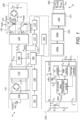
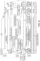
- FIG. 1 is a block diagram showing the construction of a non-contact charging system not covered by the claims, but useful for understanding the invention.
- the non-contact charging system includes a battery pack B charged by an induced electromotive force that is generated in a non-contact charger A supplied with power.
- the non-contact charger A blocks electromagnetic waves caused by Alternating Current (AC) power (110/220 V) input using an electromagnetic wave filter 100 that is connected to the power input terminal of a wireless charging pad, and a primary rectification circuit 110 rectifies the AC power, the electromagnetic waves of which are blocked, to create DC power.
- a flyback converter 110' contains a transistor, stores power transferred from the primary rectification circuit 110 while the contained transistor is turned on. In contrast, the flyback converter 110' simultaneously applies an input voltage to a gate driver 160, a central processing unit 180 and an ion generation unit 182 and a driving voltage to a series resonance type converter 120 when the contained transistor is turned off.
- a current detection unit 170 is interposed between the flyback converter 110' and the series resonance type converter 120, detects variation in current resulting from the approach of the battery pack B, and outputs a comparison current depending on variation in the current.
- the current detection unit 170 is connected to both ends of a resistor connected to the output terminal of the flyback converter 110' and the input terminal of the series resonance type converter 120, has a differential amplifier 171, to which signals output from both ends of the resistor are input, and a comparator/low-frequency filter 172, coupled to the output terminal of the differential amplifier 171.
- the current detection unit 170 detects variation in current by comparing the output voltage of the differential amplifier 171 with a predetermined reference voltage, filters out a comparison current depending on the amount of variation in current, and outputs the result.
- the central processing unit 180 detects the approach of the battery pack B using the comparison current input from the current detection unit 170, controls the gate drive 160 depending not only on whether a battery pack B approaches but also on the current of a temperature protection circuit unit 183 for stopping the switching of the gate drive 160 when abnormal operation occurs or the temperature of a foreign object placed on the non-contact charging pad exceeds a predetermined temperature. Furthermore, the central processing unit 180 performs the determination of information fed back from a dust and odor sensor 181 and switches the operation mode of the ion generation unit 182.
- the gate driver 160 outputs gate signals under the control of the central processing unit 180, and the series resonance type converter 120 adjusts the waveforms of voltage and current applied to the primary core unit 130 in response to the gate signals input from the gate driver 160.
- the gate driver 160 allows two switching devices, which are provided in the series resonance type converter 120, to be alternately turned on in response to the gate signals output by the control of the central processing unit 180, and allows the waveforms of the input voltage and current to be adjusted by charging and discharging parallel capacitors coupled to respective switching devices.
- the series resonance type converter 120 is configured to adjust the waveforms of the voltage and the current applied to the primary core unit 130 by the gate signals.
- the primary core unit 130 is configured to be switched by the series resonance type converter 120 and, therefore, generate an induced electromotive force.
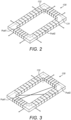
- FIGS. 2 and 3 are perspective views showing a primary core unit disposed in the non-contact charging system
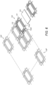
- FIGS. 4, 5 and 6 are perspective views showing the use of the primary core unit disposed in the non-contact charging system.
- the primary core unit 130 is configured such that coils Pcoil1 and Pcoil2 are wound around a plate core member 131 in which a central opening 132 is formed, and is configured such that pieces of amorphous metal or ferrite material, such as Cobalt Co, Iron Fe, Nickel Ni, Boron B or Silicon Si, having high magnetic permeability (> 80,000) and an unbroken characteristic, are attached thereto.
- amorphous metal or ferrite material such as Cobalt Co, Iron Fe, Nickel Ni, Boron B or Silicon Si, having high magnetic permeability (> 80,000) and an unbroken characteristic.
- the plate core member 131 is formed in a polygonal shape, it may be formed in either circular or elliptical shapes in addition to the polygonal shape.
- the central opening 132 is configured such that a function, which is capable both of reducing the amount of material used and of maximizing the area for radiating heat, is provided.
- the coils Pcoil1 and Pcoil2 are configured to be wound around the plate core member 131 in series or in parallel, and it is preferable to use a single wire, a paired wire, a Litz wire or a copper foil.
- the start points of the coils Pcoil1 and Pcoil2 are formed by winding the coils in the same directions, and the ends of the coils Pcoil1 and Pcoil2 are configured to be matched with Lr and Lr', respectively, and to be switched using two series resonance type converters.
- driven switching adjusts the phase of a signal Q1 and the phase of a signal Q2, thus inducing LC resonance, so that energy is stored in a secondary coil.
- the switching patterns of the coils Pcoil1 and Pcoil2 are alternately generated, so that a magnetic field shown in FIG. 7 rotates 360 , and induced energy can be stored regardless of the location of the secondary coil wound in a single direction.
- primary core units 130 and 130' can be placed on one side of the circuit 134 in series or parallel.
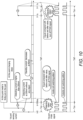
- Power rectified by the secondary rectification circuit 200 is supplied to a foreign object detection unit 220, and the supplied power is applied to a charging adjustment circuit 230a in response to the output of the foreign object detection unit 220.
- the foreign object detection unit 220 detects power at the moment at which the battery pack B that contains the secondary core unit 210, that is, a secondary module, is placed on the non-contact charger A, and is maintained in a no load state (the current of the current detection unit is smaller than a no load reference value) by maintaining a switch Q3 in an OFF state for a predetermined time (several tens of ms).
- the foreign object detection unit 220 When a predetermined period of time has lapsed after the no load state, the foreign object detection unit 220 is switched into a load state (the current of the current detection unit is larger than the no load reference value) by maintaining the switch Q3 in an ON state, and informs the primary coil through load modulation that the battery pack B containing the secondary core unit 210 has been placed on the non-contact charger A and, at the same time, applies power to a charging control unit 230.
- the current of the current detection unit 170 becomes smaller than the reference value of the no load state when the charging is completed and, at the same time, the secondary core unit 210 enters the no load state again, so that a fully-charging state is indicated by a Light Emitting Diode (LED) or a Liquid Crystal Display (LCD).
- LED Light Emitting Diode
- LCD Liquid Crystal Display
- the charging control unit 230 includes the charging adjustment circuit 230a and a fuel gauge 230b, and performs both charging adjustment and fuel gauge functions.
- the charging adjustment circuit 230a supplies the fuel gauge 230b with power rectified by the secondary rectification circuit 200, and applies voltage to a RFID control unit (not shown) in response to the output of the secondary rectification circuit 200.
- the fuel gauge 230b supplies a battery BAT through a protection circuit 240 with power supplied from the charging adjustment circuit 230a, generates charging state information and periodically records the information in the RFID control unit (not shown) while monitoring the charging state of the battery BAT.
- the protection unit is coupled between the charging control unit 230 and the battery BAT, and adjusts the charging and discharging of the battery BAT depending on whether the battery BAT is to be charged or discharged.
- the RFID control unit (not shown), the RFID information of the battery BAT is stored and, at the same time, the charging state information is periodically recorded.
- the RFID control unit When receiving an RF carrier, the RFID control unit generates RFID data, including the stored RFID and charging state information of the battery BAT, in response to the received RF carrier, modulates the RFID data, and wirelessly transmits the modulated RFID data through a tag antenna.
- the battery BAT is charged depending on the adjustment of the protection circuit unit 240.
- the charging control unit 230 is formed by integrating circuits optimized to perform both the charging control function of controlling the charging and discharging of the battery BAT using the power rectified by the secondary rectification circuit 200, and the fuel gauge function of generating the charge state information and periodically recording the generated information while monitoring the charging state of the battery B.
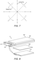
- FIG. 8 is a perspective view showing the construction of the battery pack provided in the non-contact charging system.
- the battery pack B is configured such that a shield plate 260 having a film shape is interposed between the secondary core unit 210 and a battery case 250, thus preventing the temperature of the battery BAT from increasing due to an induced electromotive force generated by the induction of an electromagnetic field and, therefore, enhancing the stability of the battery pack B, and is also configured such that sufficient electromotive force is generated by reducing the interference of the electromagnetic field caused by the induced electromotive force, thus enhancing the charging rate.
- the shield member 241 is formed in a box form so as to surround the protection circuit unit 240. It is preferred that the entire protection circuit unit 240 is formed by molding.
- FIG. 9 is a diagram illustrating an algorithm that executes when a battery pack, in which a secondary core unit is contained, is placed in the non-contact charging system.
- FIG. 10 is a diagram illustrating an algorithm that executes when a foreign object, which is made of metal, is placed on the non-contact charging system.
- FIG. 11 is a diagram illustrating the algorithm and states of the non-contact charging system.
- the foreign object detection unit 220 detects instantaneous power at the same time that a battery pack B is placed on the wireless charging pad, and allows a no load state to be maintained by maintaining the switch Q3 in an OFF state for a certain period of time.
- the foreign object detection unit 220 maintains the state at which the current of the current detection unit 170 becomes smaller than the no load reference value for the period of time, and then allows the no load state to be switched into a load state by maintaining the switch Q3 in an ON state. At this time, the current of the current detection unit 170 becomes larger than the no load reference value, so that the foreign object detection unit 220 informs the primary coil through load modulation that a battery pack B containing a secondary core unit 210 has been placed on the non-contact charger A and, at the same time applies power to the charging control unit 230.
- the current of the current detection unit 170 becomes smaller than the reference value of the no load state when the charging is completed and, at the same time, the secondary core unit 210 enters the no load state, so that a fully-charging state is indicated by a LED or a LCD.
- the power is applied to the charging control unit 230, and the operation mode of the ion generation unit 182 is switched by allowing the central processing unit 180 to determine information fed back from the odor sensor 181, so that a plurality of ions generated by the ion generation unit 182, are spread to the area around the wireless charging pad. Accordingly, the bacteria on the battery pack can be destroyed and, at the same time, the ambient air near the wireless charging pad can be purified.
- the switch Q3 is maintained in an OFF state for a certain period of time and the no load state is maintained by detecting instantaneous power at the same time that a battery pack B is placed on the wireless charging pad, and a current below the reference value is supplied and is then blocked by the central processing unit 180 to which the currents of the current detection unit 170 and the temperature protection circuit unit 183 are applied, so that damage caused by overheating is prevented.
Landscapes
- Engineering & Computer Science (AREA)
- Power Engineering (AREA)
- Computer Networks & Wireless Communication (AREA)
- Health & Medical Sciences (AREA)
- Public Health (AREA)
- Epidemiology (AREA)
- General Health & Medical Sciences (AREA)
- Animal Behavior & Ethology (AREA)
- Veterinary Medicine (AREA)
- Life Sciences & Earth Sciences (AREA)
- Signal Processing (AREA)
- Charge And Discharge Circuits For Batteries Or The Like (AREA)
- Secondary Cells (AREA)
Claims (2)
- Akku (B), umfassend:eine Akkuzelle;eine sekundäre Kerneinheit (210), die eine Induktionsspule (Scoil) umfasst, die dazu konfiguriert ist, ein Leistungssignal von einem daran angelegten Magnetfeld zu induzieren,eine sekundäre Gleichrichtungseinheit (200), die mit der Induktionsspule (Scoil) gekoppelt und dazu konfiguriert ist, das induzierte Leistungssignal gleichzurichten, um ein gleichgerichtetes Leistungssignal zu erzeugen;eine Objekterkennungseinheit (220) mit einem Schalter (Q3), wobei die Objekterkennungseinheit (220) dazu konfiguriert ist, das gleichgerichtete Leistungssignal zu empfangen und das gleichgerichtete Leistungssignal durch den Schalter (Q3) an eine Ladesteuerungseinheit zu übertragen;wobei die Ladesteuerungseinheit (230) dazu konfiguriert ist, sowohl die Steuerung des Ladens als auch des Entladens der Akkuzelle unter Verwendung der von der Objekterkennungseinheit (220) empfangenen gleichgerichteten Leistungssignals und das Erzeugen einer Ladezustandsinformation und das periodische Aufzeichnen der erzeugten Information während des Überwachens des Ladezustands der Akkuzelle durchzuführen;eine Schutzeinheit (240), die zwischen der Ladesteuerungseinheit (230) und der Akkuzelle gekoppelt ist und dazu konfiguriert ist, das Laden und Entladen der Akkuzelle in Abhängigkeit davon, ob die Akkuzelle geladen oder entladen werden muss, anzupassen; undwobei die Objekterkennungseinheit (220) konfiguriert ist zum:Erkennen von Momentanleistung zur selben Zeit, zu der der Akku (B) auf einem kontaktlosen Ladegerät (A) platziert wird;Zulassen, dass ein lastfreier Zustand aufrechterhalten wird, indem ein Schalter (Q3) für eine bestimmte Zeitdauer in einem AUS-Zustand gehalten wird;Zulassen, dass der lastfreie Zustand in einen Zustand mit Last geschaltet wird, indem der Schalter (Q3) nach dem Aufrechterhalten des lastfreien Zustands für die Zeitdauer in einem EIN-Zustand gehalten wird, wodurch eine Primärspule des kontaktlosen Ladegeräts (A) durch eine Lastmodulation darüber informiert wird, dass der Akku (B) auf dem kontaktlosen Ladegerät (A) platziert wurde, und gleichzeitig Anlegen von Leistung an die Ladesteuerungseinheit (230).
- Akku nach Anspruch 1, wobei der erste vorbestimmte Zeitraum mehrere Zehntel Millisekunden beträgt.
Applications Claiming Priority (3)
| Application Number | Priority Date | Filing Date | Title |
|---|---|---|---|
| KR1020050023184A KR100554889B1 (ko) | 2005-03-21 | 2005-03-21 | 무접점 충전 시스템 |
| PCT/KR2005/001037 WO2006101285A1 (en) | 2005-03-21 | 2005-04-11 | No point of contact charging system |
| EP05804905A EP1882292A4 (de) | 2005-03-21 | 2005-04-11 | Kontaktloses ladesystem |
Related Parent Applications (2)
| Application Number | Title | Priority Date | Filing Date |
|---|---|---|---|
| EP05804905.7 Division | 2005-04-11 | ||
| EP05804905A Division EP1882292A4 (de) | 2005-03-21 | 2005-04-11 | Kontaktloses ladesystem |
Publications (3)
| Publication Number | Publication Date |
|---|---|
| EP2390984A2 EP2390984A2 (de) | 2011-11-30 |
| EP2390984A3 EP2390984A3 (de) | 2014-05-21 |
| EP2390984B1 true EP2390984B1 (de) | 2023-07-12 |
Family
ID=37023921
Family Applications (3)
| Application Number | Title | Priority Date | Filing Date |
|---|---|---|---|
| EP05804905A Ceased EP1882292A4 (de) | 2005-03-21 | 2005-04-11 | Kontaktloses ladesystem |
| EP11178723.0A Expired - Lifetime EP2390984B1 (de) | 2005-03-21 | 2005-04-11 | Akku mit einer Objekterkennungseinheit |
| EP19159706.1A Expired - Lifetime EP3525315B1 (de) | 2005-03-21 | 2005-04-11 | Kontaktloses ladeverfahren |
Family Applications Before (1)
| Application Number | Title | Priority Date | Filing Date |
|---|---|---|---|
| EP05804905A Ceased EP1882292A4 (de) | 2005-03-21 | 2005-04-11 | Kontaktloses ladesystem |
Family Applications After (1)
| Application Number | Title | Priority Date | Filing Date |
|---|---|---|---|
| EP19159706.1A Expired - Lifetime EP3525315B1 (de) | 2005-03-21 | 2005-04-11 | Kontaktloses ladeverfahren |
Country Status (6)
| Country | Link |
|---|---|
| US (4) | US7443135B2 (de) |
| EP (3) | EP1882292A4 (de) |
| JP (1) | JP4258568B2 (de) |
| KR (1) | KR100554889B1 (de) |
| CN (1) | CN100362725C (de) |
| WO (1) | WO2006101285A1 (de) |
Families Citing this family (209)
| Publication number | Priority date | Publication date | Assignee | Title |
|---|---|---|---|---|
| KR100554889B1 (ko) | 2005-03-21 | 2006-03-03 | 주식회사 한림포스텍 | 무접점 충전 시스템 |
| CN102255398B (zh) | 2005-07-12 | 2013-07-24 | 麻省理工学院 | 无线传递电磁能量的方法和设备 |
| US7825543B2 (en) | 2005-07-12 | 2010-11-02 | Massachusetts Institute Of Technology | Wireless energy transfer |
| US8169185B2 (en) | 2006-01-31 | 2012-05-01 | Mojo Mobility, Inc. | System and method for inductive charging of portable devices |
| US11201500B2 (en) | 2006-01-31 | 2021-12-14 | Mojo Mobility, Inc. | Efficiencies and flexibilities in inductive (wireless) charging |
| US7952322B2 (en) | 2006-01-31 | 2011-05-31 | Mojo Mobility, Inc. | Inductive power source and charging system |
| CN101038616B (zh) * | 2006-03-17 | 2010-05-12 | 上海华虹集成电路有限责任公司 | 用于非接触式ic卡和射频识别标签芯片的限幅保护电路 |
| JP4618561B2 (ja) | 2006-04-28 | 2011-01-26 | 日立工機株式会社 | 電池の充電装置 |
| US11329511B2 (en) | 2006-06-01 | 2022-05-10 | Mojo Mobility Inc. | Power source, charging system, and inductive receiver for mobile devices |
| US7948208B2 (en) | 2006-06-01 | 2011-05-24 | Mojo Mobility, Inc. | Power source, charging system, and inductive receiver for mobile devices |
| KR100750201B1 (ko) | 2006-06-14 | 2007-08-17 | 주식회사 한림포스텍 | 비접촉 충전기기를 가진 가전기기로 무접점 전력전송용비접촉 콘센트 장치및 그 방법 |
| US8004235B2 (en) * | 2006-09-29 | 2011-08-23 | Access Business Group International Llc | System and method for inductively charging a battery |
| EP1914669B1 (de) * | 2006-10-18 | 2011-04-20 | Semiconductor Energy Laboratory Co., Ltd. | ID-Funktransponder |
| KR100836634B1 (ko) | 2006-10-24 | 2008-06-10 | 주식회사 한림포스텍 | 무선 데이타 통신과 전력 전송이 가능한 무접점 충전장치,충전용 배터리팩 및 무접점 충전장치를 이용한 휴대용단말기 |
| WO2008050260A1 (en) * | 2006-10-26 | 2008-05-02 | Philips Intellectual Property & Standards Gmbh | Inductive power system and method of operation |
| WO2008056415A1 (en) * | 2006-11-08 | 2008-05-15 | Panasonic Corporation | Non-contact charger, electronic device, battery pack, and non-contact charge system |
| US20080136364A1 (en) * | 2006-12-08 | 2008-06-12 | Russell Calvarese | Battery charging using thermoelectric devices |
| JP5325415B2 (ja) * | 2006-12-18 | 2013-10-23 | 株式会社半導体エネルギー研究所 | 半導体装置 |
| KR101061646B1 (ko) | 2007-02-20 | 2011-09-01 | 세이코 엡슨 가부시키가이샤 | 송전 제어 장치, 송전 장치, 전자 기기 및 무접점 전력전송 시스템 |
| EP1973069B1 (de) | 2007-03-22 | 2013-01-02 | Semiconductor Energy Laboratory Co., Ltd. | Halbleiterbauelement |
| CA3002938C (en) * | 2007-05-10 | 2021-06-29 | Auckland Uniservices Limited | Multi power sourced electric vehicle |
| US9466419B2 (en) | 2007-05-10 | 2016-10-11 | Auckland Uniservices Limited | Apparatus and system for charging a battery |
| CA2941147A1 (en) * | 2007-05-10 | 2008-11-20 | Auckland Uniservices Limited | Multi power sourced electric vehicle |
| US8805530B2 (en) | 2007-06-01 | 2014-08-12 | Witricity Corporation | Power generation for implantable devices |
| US9421388B2 (en) | 2007-06-01 | 2016-08-23 | Witricity Corporation | Power generation for implantable devices |
| KR100819753B1 (ko) * | 2007-07-13 | 2008-04-08 | 주식회사 한림포스텍 | 배터리팩 솔루션을 위한 무접점충전시스템 및 그 제어방법 |
| JP2009027781A (ja) * | 2007-07-17 | 2009-02-05 | Seiko Epson Corp | 受電制御装置、受電装置、無接点電力伝送システム、充電制御装置、バッテリ装置および電子機器 |
| JP2009087928A (ja) * | 2007-09-13 | 2009-04-23 | Semiconductor Energy Lab Co Ltd | 半導体装置およびその作製方法 |
| CN101828157B (zh) * | 2007-10-17 | 2014-08-27 | 捷通国际有限公司 | 膝上型电脑和便携电子装置无线电源系统 |
| US8729734B2 (en) * | 2007-11-16 | 2014-05-20 | Qualcomm Incorporated | Wireless power bridge |
| WO2009065419A1 (en) * | 2007-11-20 | 2009-05-28 | Nokia Corporation | Wireless galvanic charging device, method of operation thereof and mobile electronic device to be charged |
| EP2226885B1 (de) * | 2007-11-28 | 2013-05-01 | Olympus Medical Systems Corp. | Batterieverwaltungssystem und ladegerät |
| KR100971748B1 (ko) * | 2007-11-30 | 2010-07-22 | 정춘길 | 근거리 무선 전력전송 시스템 |
| KR100971737B1 (ko) * | 2007-11-30 | 2010-07-21 | 정춘길 | 멀티무접점충전시스템 및 제어방법 |
| KR100971734B1 (ko) * | 2007-11-30 | 2010-07-21 | 정춘길 | 멀티무접점충전이 가능한 무접점전력전송장치 |
| WO2009069844A1 (en) * | 2007-11-30 | 2009-06-04 | Chun-Kil Jung | Multiple non-contact charging system of wireless power transmision and control method thereof |
| KR100998683B1 (ko) * | 2007-11-30 | 2010-12-07 | 정춘길 | 멀티무접점전력충전이 가능한 무접점전력수신장치 |
| JP5556002B2 (ja) * | 2008-01-09 | 2014-07-23 | セイコーエプソン株式会社 | 送電制御装置、送電装置、無接点電力伝送システムおよび電子機器 |
| KR100976161B1 (ko) * | 2008-02-20 | 2010-08-16 | 정춘길 | 무접점충전시스템 및 그의 충전제어방법 |
| US20090278494A1 (en) * | 2008-03-03 | 2009-11-12 | Mitch Randall | Universal electrical interface for providing power to mobile devices |
| JP5188211B2 (ja) * | 2008-03-07 | 2013-04-24 | キヤノン株式会社 | 給電装置及び給電方法 |
| US8338990B2 (en) * | 2008-03-13 | 2012-12-25 | Access Business Group International Llc | Inductive power supply system with multiple coil primary |
| KR101094253B1 (ko) * | 2008-04-28 | 2011-12-19 | 정춘길 | 무선 전력 수신 장치, 이와 관련된 무선 전력 송신 장치, 그리고, 무선 전력 송수신 시스템 |
| US20110050164A1 (en) | 2008-05-07 | 2011-03-03 | Afshin Partovi | System and methods for inductive charging, and improvements and uses thereof |
| JP2009273327A (ja) * | 2008-05-10 | 2009-11-19 | Sanyo Electric Co Ltd | 電池内蔵機器と充電台 |
| US20090284369A1 (en) | 2008-05-13 | 2009-11-19 | Qualcomm Incorporated | Transmit power control for a wireless charging system |
| JP4725664B2 (ja) * | 2008-06-25 | 2011-07-13 | セイコーエプソン株式会社 | 送電制御装置、送電装置、受電制御装置、受電装置、電子機器、送電制御方法、及び受電制御方法 |
| US8248024B2 (en) * | 2008-08-15 | 2012-08-21 | Microsoft Corporation | Advanced inductive charging pad for portable devices |
| WO2010032573A1 (en) * | 2008-09-17 | 2010-03-25 | Semiconductor Energy Laboratory Co., Ltd. | Semiconductor device |
| GB0817047D0 (en) * | 2008-09-18 | 2008-10-22 | Amway Europ Ltd | Electromagnetic Interference Suppression |
| WO2010032603A1 (en) | 2008-09-19 | 2010-03-25 | Semiconductor Energy Laboratory Co., Ltd. | Semiconductor device and wireless tag using the same |
| US8482158B2 (en) | 2008-09-27 | 2013-07-09 | Witricity Corporation | Wireless energy transfer using variable size resonators and system monitoring |
| US9035499B2 (en) | 2008-09-27 | 2015-05-19 | Witricity Corporation | Wireless energy transfer for photovoltaic panels |
| US9396867B2 (en) | 2008-09-27 | 2016-07-19 | Witricity Corporation | Integrated resonator-shield structures |
| US8692412B2 (en) | 2008-09-27 | 2014-04-08 | Witricity Corporation | Temperature compensation in a wireless transfer system |
| US9106203B2 (en) | 2008-09-27 | 2015-08-11 | Witricity Corporation | Secure wireless energy transfer in medical applications |
| US8907531B2 (en) | 2008-09-27 | 2014-12-09 | Witricity Corporation | Wireless energy transfer with variable size resonators for medical applications |
| US8901778B2 (en) | 2008-09-27 | 2014-12-02 | Witricity Corporation | Wireless energy transfer with variable size resonators for implanted medical devices |
| US9093853B2 (en) | 2008-09-27 | 2015-07-28 | Witricity Corporation | Flexible resonator attachment |
| US8497601B2 (en) | 2008-09-27 | 2013-07-30 | Witricity Corporation | Wireless energy transfer converters |
| US9601270B2 (en) | 2008-09-27 | 2017-03-21 | Witricity Corporation | Low AC resistance conductor designs |
| US8901779B2 (en) | 2008-09-27 | 2014-12-02 | Witricity Corporation | Wireless energy transfer with resonator arrays for medical applications |
| US9105959B2 (en) | 2008-09-27 | 2015-08-11 | Witricity Corporation | Resonator enclosure |
| US9246336B2 (en) | 2008-09-27 | 2016-01-26 | Witricity Corporation | Resonator optimizations for wireless energy transfer |
| US9160203B2 (en) | 2008-09-27 | 2015-10-13 | Witricity Corporation | Wireless powered television |
| US8598743B2 (en) | 2008-09-27 | 2013-12-03 | Witricity Corporation | Resonator arrays for wireless energy transfer |
| US8963488B2 (en) | 2008-09-27 | 2015-02-24 | Witricity Corporation | Position insensitive wireless charging |
| US8643326B2 (en) | 2008-09-27 | 2014-02-04 | Witricity Corporation | Tunable wireless energy transfer systems |
| US8922066B2 (en) | 2008-09-27 | 2014-12-30 | Witricity Corporation | Wireless energy transfer with multi resonator arrays for vehicle applications |
| US8928276B2 (en) | 2008-09-27 | 2015-01-06 | Witricity Corporation | Integrated repeaters for cell phone applications |
| US8723366B2 (en) | 2008-09-27 | 2014-05-13 | Witricity Corporation | Wireless energy transfer resonator enclosures |
| US8912687B2 (en) | 2008-09-27 | 2014-12-16 | Witricity Corporation | Secure wireless energy transfer for vehicle applications |
| US8933594B2 (en) | 2008-09-27 | 2015-01-13 | Witricity Corporation | Wireless energy transfer for vehicles |
| US8946938B2 (en) | 2008-09-27 | 2015-02-03 | Witricity Corporation | Safety systems for wireless energy transfer in vehicle applications |
| US8957549B2 (en) | 2008-09-27 | 2015-02-17 | Witricity Corporation | Tunable wireless energy transfer for in-vehicle applications |
| US9184595B2 (en) | 2008-09-27 | 2015-11-10 | Witricity Corporation | Wireless energy transfer in lossy environments |
| US9744858B2 (en) | 2008-09-27 | 2017-08-29 | Witricity Corporation | System for wireless energy distribution in a vehicle |
| US9544683B2 (en) | 2008-09-27 | 2017-01-10 | Witricity Corporation | Wirelessly powered audio devices |
| US9318922B2 (en) | 2008-09-27 | 2016-04-19 | Witricity Corporation | Mechanically removable wireless power vehicle seat assembly |
| US9577436B2 (en) | 2008-09-27 | 2017-02-21 | Witricity Corporation | Wireless energy transfer for implantable devices |
| US9515494B2 (en) | 2008-09-27 | 2016-12-06 | Witricity Corporation | Wireless power system including impedance matching network |
| US9601266B2 (en) | 2008-09-27 | 2017-03-21 | Witricity Corporation | Multiple connected resonators with a single electronic circuit |
| US9065423B2 (en) | 2008-09-27 | 2015-06-23 | Witricity Corporation | Wireless energy distribution system |
| US8772973B2 (en) | 2008-09-27 | 2014-07-08 | Witricity Corporation | Integrated resonator-shield structures |
| US8937408B2 (en) | 2008-09-27 | 2015-01-20 | Witricity Corporation | Wireless energy transfer for medical applications |
| US8947186B2 (en) | 2008-09-27 | 2015-02-03 | Witricity Corporation | Wireless energy transfer resonator thermal management |
| US8669676B2 (en) | 2008-09-27 | 2014-03-11 | Witricity Corporation | Wireless energy transfer across variable distances using field shaping with magnetic materials to improve the coupling factor |
| US9601261B2 (en) * | 2008-09-27 | 2017-03-21 | Witricity Corporation | Wireless energy transfer using repeater resonators |
| WO2010038712A1 (en) * | 2008-09-30 | 2010-04-08 | Semiconductor Energy Laboratory Co., Ltd. | Semiconductor device |
| US8362651B2 (en) | 2008-10-01 | 2013-01-29 | Massachusetts Institute Of Technology | Efficient near-field wireless energy transfer using adiabatic system variations |
| JP5319469B2 (ja) | 2008-10-03 | 2013-10-16 | 株式会社半導体エネルギー研究所 | Rfidタグ |
| WO2010067763A1 (ja) * | 2008-12-09 | 2010-06-17 | 株式会社 豊田自動織機 | 非接触電力伝送装置及び非接触電力伝送装置における電力伝送方法 |
| EP2357716B1 (de) | 2008-12-12 | 2017-08-30 | Intel Corporation | Kontaktlose kraftübertragungsvorrichtung |
| JP5285418B2 (ja) * | 2008-12-24 | 2013-09-11 | 株式会社豊田自動織機 | 共鳴型非接触電力供給装置 |
| US20100201312A1 (en) | 2009-02-10 | 2010-08-12 | Qualcomm Incorporated | Wireless power transfer for portable enclosures |
| US9312924B2 (en) | 2009-02-10 | 2016-04-12 | Qualcomm Incorporated | Systems and methods relating to multi-dimensional wireless charging |
| US20100237013A1 (en) * | 2009-02-13 | 2010-09-23 | Millipore Corporation | Autonomous filter element |
| US8452235B2 (en) * | 2009-03-28 | 2013-05-28 | Qualcomm, Incorporated | Tracking receiver devices with wireless power systems, apparatuses, and methods |
| EP2436096B1 (de) | 2009-05-25 | 2016-07-13 | Koninklijke Philips N.V. | Verfahren und einrichtung zum detektieren einer einrichtung in einem drahtlosen energieübertragungssystem |
| USD611898S1 (en) | 2009-07-17 | 2010-03-16 | Lin Wei Yang | Induction charger |
| JP5434330B2 (ja) | 2009-07-22 | 2014-03-05 | ソニー株式会社 | 電力受信装置、電力伝送システム、充電装置および電力伝送方法 |
| CN102474133A (zh) * | 2009-07-23 | 2012-05-23 | 富士通株式会社 | 送电装置、无线电力供应系统、以及无线电力供应装置 |
| NZ597748A (en) | 2009-07-24 | 2013-12-20 | Access Business Group Int Llc | A wireless power supply |
| USD611900S1 (en) | 2009-07-31 | 2010-03-16 | Lin Wei Yang | Induction charger |
| USD611899S1 (en) | 2009-07-31 | 2010-03-16 | Lin Wei Yang | Induction charger |
| KR100992480B1 (ko) | 2009-09-10 | 2010-11-05 | 주식회사 한림포스텍 | 피드백신호에 의한 이물질 감지기능을 갖는 무접점 충전 시스템 |
| KR101084904B1 (ko) * | 2009-10-07 | 2011-11-18 | 삼성전기주식회사 | 통신 기능이 구비된 무선전력 송수신 장치 및 그 무선전력 송수신 방법 |
| CN105048643B (zh) * | 2010-02-08 | 2018-08-03 | 飞利浦知识产权企业有限公司 | 输入寄生金属检测 |
| JP2011211760A (ja) * | 2010-03-26 | 2011-10-20 | Panasonic Electric Works Co Ltd | 非接触給電装置及び非接触充電システム |
| CN107040043B (zh) * | 2010-05-19 | 2019-06-11 | 韦特里西提公司 | 自适应无线能量传送系统 |
| EP2393181B1 (de) * | 2010-06-02 | 2019-09-04 | FRIWO Gerätebau GmbH | Schaltung für ein System zur kontaklosen, induktiven Energieübertragung |
| WO2011156768A2 (en) * | 2010-06-11 | 2011-12-15 | Mojo Mobility, Inc. | System for wireless power transfer that supports interoperability, and multi-pole magnets for use therewith |
| CN102299570A (zh) * | 2010-06-24 | 2011-12-28 | 海尔集团公司 | 无线传输系统 |
| IT1400748B1 (it) * | 2010-06-30 | 2013-07-02 | St Microelectronics Srl | Apparato per il trasferimento wireless di energia fra due dispositivi e contemporaneo trasferimento di dati. |
| KR101188241B1 (ko) | 2010-07-15 | 2012-10-05 | 주식회사 만도 | 전기 자동차용 상용 전원 완속 충전기 |
| KR101110282B1 (ko) * | 2010-07-16 | 2012-02-15 | 정춘길 | 무접점 전력 수신 장치 및 무접점 전력 전송 장치의 무접점 전력 전송 제어 방법 |
| US9853478B2 (en) * | 2010-07-28 | 2017-12-26 | Qualcomm Incorporated | Low power detection of wireless power devices |
| US9602168B2 (en) | 2010-08-31 | 2017-03-21 | Witricity Corporation | Communication in wireless energy transfer systems |
| JP5691337B2 (ja) * | 2010-09-17 | 2015-04-01 | ソニー株式会社 | 電力供給システム、充電制御装置及びバッテリ装置 |
| US9219378B2 (en) | 2010-11-01 | 2015-12-22 | Qualcomm Incorporated | Wireless charging of devices |
| US9178369B2 (en) | 2011-01-18 | 2015-11-03 | Mojo Mobility, Inc. | Systems and methods for providing positioning freedom, and support of different voltages, protocols, and power levels in a wireless power system |
| US11342777B2 (en) | 2011-01-18 | 2022-05-24 | Mojo Mobility, Inc. | Powering and/or charging with more than one protocol |
| US9356659B2 (en) | 2011-01-18 | 2016-05-31 | Mojo Mobility, Inc. | Chargers and methods for wireless power transfer |
| US9496732B2 (en) | 2011-01-18 | 2016-11-15 | Mojo Mobility, Inc. | Systems and methods for wireless power transfer |
| US10115520B2 (en) | 2011-01-18 | 2018-10-30 | Mojo Mobility, Inc. | Systems and method for wireless power transfer |
| DE102011005682A1 (de) * | 2011-03-17 | 2012-09-20 | Robert Bosch Gmbh | Ladegerät, Akku und verfahren zur Erkennung eines Fremdobjekts |
| US9912201B2 (en) | 2011-04-11 | 2018-03-06 | Texas Instruments Incorporated | Systems and methods of detecting a change in object presence in a magnetic field |
| JP5071574B1 (ja) | 2011-07-05 | 2012-11-14 | ソニー株式会社 | 検知装置、受電装置、非接触電力伝送システム及び検知方法 |
| US9948145B2 (en) | 2011-07-08 | 2018-04-17 | Witricity Corporation | Wireless power transfer for a seat-vest-helmet system |
| JP5840886B2 (ja) * | 2011-07-25 | 2016-01-06 | ソニー株式会社 | 検知装置、受電装置、送電装置、非接触電力伝送システム及び検知方法 |
| KR20140053282A (ko) | 2011-08-04 | 2014-05-07 | 위트리시티 코포레이션 | 튜닝 가능한 무선 전력 아키텍처 |
| KR20130024757A (ko) * | 2011-08-29 | 2013-03-08 | 주식회사 케이더파워 | 이종 충전 방식을 가진 무선 충전 시스템 |
| EP2754222B1 (de) | 2011-09-09 | 2015-11-18 | Witricity Corporation | Fremdkörpererkennung in drahtlosen energieübertragungssystemen |
| US9252846B2 (en) * | 2011-09-09 | 2016-02-02 | Qualcomm Incorporated | Systems and methods for detecting and identifying a wireless power device |
| US20130062966A1 (en) | 2011-09-12 | 2013-03-14 | Witricity Corporation | Reconfigurable control architectures and algorithms for electric vehicle wireless energy transfer systems |
| US9318257B2 (en) | 2011-10-18 | 2016-04-19 | Witricity Corporation | Wireless energy transfer for packaging |
| CN103988391A (zh) | 2011-11-04 | 2014-08-13 | WiTricity公司 | 无线能量传输建模工具 |
| JP6060516B2 (ja) | 2011-11-30 | 2017-01-18 | ソニー株式会社 | 電子機器および給電システム |
| EP2793173A4 (de) * | 2011-12-14 | 2015-08-05 | Mobiles endgerät und verfahren zur einstellung einer rfid-antennenresonanzfrequenz dafür | |
| NZ716301A (en) | 2011-12-22 | 2017-01-27 | Treefrog Dev Inc | Electronic device housing with battery |
| CN102545398B (zh) * | 2012-01-20 | 2014-01-15 | 北京科技大学 | 用于旋转体轴载电子设备的非接触供电装置 |
| US9306635B2 (en) | 2012-01-26 | 2016-04-05 | Witricity Corporation | Wireless energy transfer with reduced fields |
| JP5924964B2 (ja) * | 2012-02-07 | 2016-05-25 | シャープ株式会社 | 通信端末 |
| US9722447B2 (en) | 2012-03-21 | 2017-08-01 | Mojo Mobility, Inc. | System and method for charging or powering devices, such as robots, electric vehicles, or other mobile devices or equipment |
| US9558883B2 (en) * | 2012-05-02 | 2017-01-31 | Samsung Electronics Co., Ltd | Power transmitter and method for controlling power transmission |
| US8789282B2 (en) | 2012-05-25 | 2014-07-29 | Shavelogic, Inc. | Magnetic attachment for shaving cartridge |
| US9343922B2 (en) | 2012-06-27 | 2016-05-17 | Witricity Corporation | Wireless energy transfer for rechargeable batteries |
| AU2013296585B2 (en) | 2012-07-30 | 2017-02-23 | Treefrog Developments, Inc. | Weatherproof loudspeaker and speaker assembly |
| US9287607B2 (en) | 2012-07-31 | 2016-03-15 | Witricity Corporation | Resonator fine tuning |
| US9595378B2 (en) | 2012-09-19 | 2017-03-14 | Witricity Corporation | Resonator enclosure |
| WO2014063159A2 (en) | 2012-10-19 | 2014-04-24 | Witricity Corporation | Foreign object detection in wireless energy transfer systems |
| KR101441994B1 (ko) | 2012-11-14 | 2014-09-18 | 파나소닉 주식회사 | 비접촉 급전 장치 |
| US9449757B2 (en) | 2012-11-16 | 2016-09-20 | Witricity Corporation | Systems and methods for wireless power system with improved performance and/or ease of use |
| PT2936647T (pt) * | 2012-12-18 | 2017-07-12 | Nucleus Scient Inc | Identificação de sistema não linear para a detecção de objectos num sistema de transferência de energia sem fios |
| KR20140099822A (ko) * | 2013-02-04 | 2014-08-13 | 엘지전자 주식회사 | 무선 전력 전송장치 및 이를 구비하는 무선충전시스템 |
| US9837846B2 (en) | 2013-04-12 | 2017-12-05 | Mojo Mobility, Inc. | System and method for powering or charging receivers or devices having small surface areas or volumes |
| KR101949954B1 (ko) | 2013-06-07 | 2019-02-19 | 삼성전자주식회사 | 고효율 에너지 주입을 위한 무선 전력 전송 장치 |
| US9893557B2 (en) | 2013-07-12 | 2018-02-13 | Schneider Electric USA, Inc. | Method and device for foreign object detection in induction electric charger |
| US10263451B2 (en) | 2013-08-09 | 2019-04-16 | Intel Corporation | Coil for mobile device context-driven switching and wireless charging |
| EP3039770B1 (de) | 2013-08-14 | 2020-01-22 | WiTricity Corporation | Impedanzabstimmung |
| US9780573B2 (en) | 2014-02-03 | 2017-10-03 | Witricity Corporation | Wirelessly charged battery system |
| WO2015123614A2 (en) | 2014-02-14 | 2015-08-20 | Witricity Corporation | Object detection for wireless energy transfer systems |
| JP6499185B2 (ja) | 2014-02-23 | 2019-04-10 | アップル インコーポレイテッドApple Inc. | 誘導電力伝送システムのインピーダンス整合 |
| WO2015161035A1 (en) | 2014-04-17 | 2015-10-22 | Witricity Corporation | Wireless power transfer systems with shield openings |
| US9842687B2 (en) | 2014-04-17 | 2017-12-12 | Witricity Corporation | Wireless power transfer systems with shaped magnetic components |
| US9450446B2 (en) * | 2014-04-28 | 2016-09-20 | Apple Inc. | Connector-free magnetic charger/winder |
| US9837860B2 (en) | 2014-05-05 | 2017-12-05 | Witricity Corporation | Wireless power transmission systems for elevators |
| WO2015171910A1 (en) | 2014-05-07 | 2015-11-12 | Witricity Corporation | Foreign object detection in wireless energy transfer systems |
| US10032557B1 (en) | 2014-05-29 | 2018-07-24 | Apple Inc. | Tuning of primary and secondary resonant frequency for improved efficiency of inductive power transfer |
| US9537353B1 (en) | 2014-06-03 | 2017-01-03 | Apple Inc. | Methods for detecting mated coils |
| US9685814B1 (en) | 2014-06-13 | 2017-06-20 | Apple Inc. | Detection of coil coupling in an inductive charging system |
| WO2015196123A2 (en) | 2014-06-20 | 2015-12-23 | Witricity Corporation | Wireless power transfer systems for surfaces |
| US10574091B2 (en) | 2014-07-08 | 2020-02-25 | Witricity Corporation | Enclosures for high power wireless power transfer systems |
| CN107258046B (zh) | 2014-07-08 | 2020-07-17 | 无线电力公司 | 无线电力传送系统中的谐振器均衡 |
| US9813041B1 (en) | 2014-07-31 | 2017-11-07 | Apple Inc. | Automatic boost control for resonant coupled coils |
| US10014733B2 (en) | 2014-08-28 | 2018-07-03 | Apple Inc. | Temperature management in a wireless energy transfer system |
| US10193372B2 (en) | 2014-09-02 | 2019-01-29 | Apple Inc. | Operating an inductive energy transfer system |
| US10003218B2 (en) * | 2014-12-20 | 2018-06-19 | Intel Corporation | Chassis design for wireless-charging coil integration for computing systems |
| US9843217B2 (en) | 2015-01-05 | 2017-12-12 | Witricity Corporation | Wireless energy transfer for wearables |
| JP2016127740A (ja) * | 2015-01-06 | 2016-07-11 | 東芝テック株式会社 | 情報処理装置及び周辺機器 |
| US9829599B2 (en) | 2015-03-23 | 2017-11-28 | Schneider Electric USA, Inc. | Sensor and method for foreign object detection in induction electric charger |
| US9425644B1 (en) | 2015-06-03 | 2016-08-23 | Thor Charger Company | Method and apparatus for charging an electrically chargeable device utilizing resonating magnetic oscillations in the apparatus |
| US10148117B2 (en) | 2015-06-29 | 2018-12-04 | Wireless Advanced Vehicle Electrification, Inc. | Low inductance pad winding using a matched winding of multiple spirals |
| US10666084B2 (en) | 2015-07-10 | 2020-05-26 | Apple Inc. | Detection and notification of an unpowered releasable charging device |
| WO2017062647A1 (en) | 2015-10-06 | 2017-04-13 | Witricity Corporation | Rfid tag and transponder detection in wireless energy transfer systems |
| CN108700620B (zh) | 2015-10-14 | 2021-03-05 | 无线电力公司 | 无线能量传输系统中的相位和振幅检测 |
| US10063110B2 (en) | 2015-10-19 | 2018-08-28 | Witricity Corporation | Foreign object detection in wireless energy transfer systems |
| EP3365958B1 (de) | 2015-10-22 | 2020-05-27 | WiTricity Corporation | Dynamische abstimmung in system zum drahtlosen energietransfer |
| US11689856B2 (en) | 2015-11-19 | 2023-06-27 | The Lovesac Company | Electronic furniture systems with integrated induction charger |
| US10212519B2 (en) | 2015-11-19 | 2019-02-19 | The Lovesac Company | Electronic furniture systems with integrated internal speakers |
| US10075019B2 (en) | 2015-11-20 | 2018-09-11 | Witricity Corporation | Voltage source isolation in wireless power transfer systems |
| EP3462574B1 (de) | 2016-02-02 | 2021-11-17 | WiTricity Corporation | Steuerung von system zur drahtlosen stromübertragung |
| CA3012697A1 (en) | 2016-02-08 | 2017-08-17 | Witricity Corporation | Pwm capacitor control |
| KR101698045B1 (ko) * | 2016-09-05 | 2017-01-20 | 김재범 | 단말용 무선충전기가 구비된 공기 청정기 |
| US10644531B1 (en) | 2016-09-22 | 2020-05-05 | Apple Inc. | Adaptable power rectifier for wireless charger system |
| JP6342066B1 (ja) * | 2017-02-08 | 2018-06-13 | 三菱電機エンジニアリング株式会社 | 送電側機器 |
| US10523063B2 (en) | 2017-04-07 | 2019-12-31 | Apple Inc. | Common mode noise compensation in wireless power systems |
| US10389274B2 (en) | 2017-04-07 | 2019-08-20 | Apple Inc. | Boosted output inverter for electronic devices |
| EP3646434B1 (de) | 2017-06-29 | 2025-01-22 | Witricity Corporation | Schutz und steuerung von drahtlosen stromsystemen |
| WO2019126828A1 (en) | 2017-12-22 | 2019-06-27 | Wireless Advanced Vehicle Electrification, Inc. | Wireless power transfer pad with multiple windings |
| CN108054574B (zh) * | 2017-12-25 | 2025-01-10 | 卧龙电气集团辽宁荣信电气传动有限公司 | 一种用于岸基船只充电的连接结构 |
| US11462943B2 (en) | 2018-01-30 | 2022-10-04 | Wireless Advanced Vehicle Electrification, Llc | DC link charging of capacitor in a wireless power transfer pad |
| US11437854B2 (en) | 2018-02-12 | 2022-09-06 | Wireless Advanced Vehicle Electrification, Llc | Variable wireless power transfer system |
| US11444485B2 (en) | 2019-02-05 | 2022-09-13 | Mojo Mobility, Inc. | Inductive charging system with charging electronics physically separated from charging coil |
| KR102802132B1 (ko) * | 2019-02-20 | 2025-04-28 | 삼성에스디아이 주식회사 | 배터리 제어 장치 및 배터리 제어 방법 |
| US11243264B2 (en) * | 2020-04-22 | 2022-02-08 | Renesas Electronics Corporation | Abnormal power supply voltage detection device and method for detecting abnormal power supply voltage |
| KR102419356B1 (ko) * | 2020-06-26 | 2022-07-11 | 이종성 | 살균 기능을 구비한 휴대폰 충전기 |
| CN112288068B (zh) * | 2020-10-24 | 2024-02-27 | 卓捷创芯科技(深圳)有限公司 | 一种无源射频识别标签的正反馈闩锁限幅控制电路和方法 |
| CN114498959B (zh) * | 2020-11-12 | 2025-10-10 | 台达电子企业管理(上海)有限公司 | 无线电能传输装置的异物检测方法和装置 |
Family Cites Families (30)
| Publication number | Priority date | Publication date | Assignee | Title |
|---|---|---|---|---|
| JPH0467732A (ja) | 1990-07-06 | 1992-03-03 | Seiko Instr Inc | 無線充電システム |
| US5568036A (en) | 1994-12-02 | 1996-10-22 | Delco Electronics Corp. | Contactless battery charging system with high voltage cable |
| JPH0913037A (ja) | 1995-07-03 | 1997-01-14 | Nippon Carbide Ind Co Inc | カプセル化された難燃剤組成物 |
| JPH09103037A (ja) | 1995-10-05 | 1997-04-15 | Nippon Ido Tsushin Kk | 給電装置、被給電装置および給電システム |
| JPH1014124A (ja) * | 1996-06-19 | 1998-01-16 | Tdk Corp | 非接触電力伝送装置 |
| US5963012A (en) | 1998-07-13 | 1999-10-05 | Motorola, Inc. | Wireless battery charging system having adaptive parameter sensing |
| DE19837675A1 (de) * | 1998-08-19 | 2000-02-24 | Nokia Technology Gmbh | Ladevorrichtung für Akkumulatoren in einem mobilen elektrischen Gerät mit induktiver Energieübertragung |
| KR20020035242A (ko) | 2000-11-06 | 2002-05-11 | 조규형 | 유도 결합에 의한 휴대 이동 장치용 축전지의 비접촉식충전 장치 |
| KR100566220B1 (ko) * | 2001-01-05 | 2006-03-29 | 삼성전자주식회사 | 무접점 배터리 충전기 |
| KR20020057469A (ko) | 2001-01-05 | 2002-07-11 | 윤종용 | 코어 없는 초박형 프린트회로기판 변압기 및 그프린트회로기판 변압기를 이용한 무접점 배터리 충전기 |
| JP2002209344A (ja) | 2001-01-12 | 2002-07-26 | Matsushita Electric Works Ltd | 非接触電力伝送装置 |
| JP2002272020A (ja) * | 2001-03-09 | 2002-09-20 | Sony Corp | 非接触電力伝送装置及び非接触充電装置 |
| US20030001543A1 (en) | 2001-06-28 | 2003-01-02 | Eisenbraun Kenneth D. | Device charger |
| DE10158794B4 (de) * | 2001-11-30 | 2008-05-29 | Friwo Gerätebau Gmbh | Induktiver kontaktloser Leistungsübertrager |
| WO2003105308A1 (en) * | 2002-01-11 | 2003-12-18 | City University Of Hong Kong | Planar inductive battery charger |
| US7239110B2 (en) | 2002-05-13 | 2007-07-03 | Splashpower Limited | Primary units, methods and systems for contact-less power transfer |
| GB2388716B (en) * | 2002-05-13 | 2004-10-20 | Splashpower Ltd | Improvements relating to contact-less power transfer |
| US6906495B2 (en) | 2002-05-13 | 2005-06-14 | Splashpower Limited | Contact-less power transfer |
| GB0210886D0 (en) | 2002-05-13 | 2002-06-19 | Zap Wireless Technologies Ltd | Improvements relating to contact-less power transfer |
| US6844702B2 (en) * | 2002-05-16 | 2005-01-18 | Koninklijke Philips Electronics N.V. | System, method and apparatus for contact-less battery charging with dynamic control |
| US6909495B2 (en) | 2002-08-13 | 2005-06-21 | Diamond Power International, Inc. | Emissivity probe |
| KR20040048286A (ko) | 2002-12-02 | 2004-06-07 | 이효상 | 인터넷 상에서 게임을 이용한 가변형 당첨 확률 복권서비스 제공시스템 및 그 방법 |
| KR100488524B1 (ko) * | 2003-04-09 | 2005-05-11 | 삼성전자주식회사 | 로봇충전장치 |
| EP1432097A1 (de) | 2003-10-06 | 2004-06-23 | Siemens Aktiengesellschaft | Verfahren und Anordnung zum berührungslosen Laden eines Mobilgeräts |
| CN2666013Y (zh) * | 2003-10-31 | 2004-12-22 | 宏碁股份有限公司 | 非接触感应式的手持装置充电装置 |
| KR100564256B1 (ko) * | 2004-06-25 | 2006-03-29 | 주식회사 한림포스텍 | 무선주파수 식별기술이 적용된 무선 충전용 패드 및배터리팩 |
| KR100554889B1 (ko) | 2005-03-21 | 2006-03-03 | 주식회사 한림포스텍 | 무접점 충전 시스템 |
| KR100976161B1 (ko) * | 2008-02-20 | 2010-08-16 | 정춘길 | 무접점충전시스템 및 그의 충전제어방법 |
| KR200448286Y1 (ko) | 2010-01-20 | 2010-03-29 | 이정미 | 경조사용 병풍 조형물 |
| KR101850487B1 (ko) * | 2011-06-21 | 2018-04-19 | 삼성전자주식회사 | 전력공급제어장치 |
-
2005
- 2005-03-21 KR KR1020050023184A patent/KR100554889B1/ko not_active Expired - Lifetime
- 2005-04-11 US US10/570,041 patent/US7443135B2/en not_active Ceased
- 2005-04-11 EP EP05804905A patent/EP1882292A4/de not_active Ceased
- 2005-04-11 CN CNB2005800006685A patent/CN100362725C/zh not_active Expired - Lifetime
- 2005-04-11 JP JP2007509392A patent/JP4258568B2/ja not_active Expired - Lifetime
- 2005-04-11 US US12/914,303 patent/USRE44038E1/en not_active Ceased
- 2005-04-11 WO PCT/KR2005/001037 patent/WO2006101285A1/en not_active Ceased
- 2005-04-11 US US13/750,494 patent/USRE48193E1/en active Active
- 2005-04-11 EP EP11178723.0A patent/EP2390984B1/de not_active Expired - Lifetime
- 2005-04-11 EP EP19159706.1A patent/EP3525315B1/de not_active Expired - Lifetime
-
2013
- 2013-01-25 US US13/750,494 patent/US20130154559A1/en active Granted
Also Published As
| Publication number | Publication date |
|---|---|
| EP3525315B1 (de) | 2025-03-05 |
| US20080094027A1 (en) | 2008-04-24 |
| WO2006101285A1 (en) | 2006-09-28 |
| US20130154559A1 (en) | 2013-06-20 |
| US7443135B2 (en) | 2008-10-28 |
| USRE48193E1 (en) | 2020-09-01 |
| JP4258568B2 (ja) | 2009-04-30 |
| EP1882292A4 (de) | 2010-08-11 |
| JP2007514400A (ja) | 2007-05-31 |
| KR100554889B1 (ko) | 2006-03-03 |
| EP2390984A2 (de) | 2011-11-30 |
| USRE44038E1 (en) | 2013-03-05 |
| CN100362725C (zh) | 2008-01-16 |
| CN1826715A (zh) | 2006-08-30 |
| EP1882292A1 (de) | 2008-01-30 |
| EP2390984A3 (de) | 2014-05-21 |
| EP3525315A1 (de) | 2019-08-14 |
Similar Documents
| Publication | Publication Date | Title |
|---|---|---|
| EP2390984B1 (de) | Akku mit einer Objekterkennungseinheit | |
| US8159183B2 (en) | Contact-less power supply, contact-less charger systems and method for charging rechargeable battery cell | |
| KR100564256B1 (ko) | 무선주파수 식별기술이 적용된 무선 충전용 패드 및배터리팩 | |
| US10050478B2 (en) | Receiver for wireless charging system for portable electronic device | |
| EP3136540B1 (de) | Kontaktloses ladersystem einer drahtlosen stromübertragung für eine batterie und steuerungsverfahren dafür | |
| US8129942B2 (en) | Contactless charging method for charging battery | |
| EP2781003B1 (de) | Systeme und verfahren zum induktiven laden in einem geschlossenen magnetischen kreis | |
| US20140266018A1 (en) | Systems and methods for extending the power capability of a wireless charger | |
| KR101250266B1 (ko) | 용량이 다른 이동기기 배터리를 충전하는 무선 충전 패드 및 그 충전 방법 | |
| KR20080032519A (ko) | 충전전력 공급장치, 배터리 장치, 무접점 충전 시스템 및충전 방법 | |
| KR100595702B1 (ko) | 양방향 충전이 가능한 무선 충전용 패드 및 배터리팩 | |
| EP1962365A1 (de) | Batteriesystem mit kontaktloser ladung, ladegerät und batteriepack | |
| KR100564255B1 (ko) | 무접점 충전 배터리팩, 이 배터리팩들간의 무선 충전 방법및 그 시스템 | |
| KR20060002325A (ko) | 배터리 정보처리용 집적회로 및 그와 연계되는 무선충전용 집적회로 |
Legal Events
| Date | Code | Title | Description |
|---|---|---|---|
| 17P | Request for examination filed |
Effective date: 20110824 |
|
| AC | Divisional application: reference to earlier application |
Ref document number: 1882292 Country of ref document: EP Kind code of ref document: P |
|
| AK | Designated contracting states |
Kind code of ref document: A2 Designated state(s): DE GB |
|
| PUAI | Public reference made under article 153(3) epc to a published international application that has entered the european phase |
Free format text: ORIGINAL CODE: 0009012 |
|
| PUAL | Search report despatched |
Free format text: ORIGINAL CODE: 0009013 |
|
| AK | Designated contracting states |
Kind code of ref document: A3 Designated state(s): DE GB |
|
| RIC1 | Information provided on ipc code assigned before grant |
Ipc: H02J 7/02 20060101AFI20140411BHEP |
|
| RAP1 | Party data changed (applicant data changed or rights of an application transferred) |
Owner name: GE HYBRID TECHNOLOGIES, LLC |
|
| STAA | Information on the status of an ep patent application or granted ep patent |
Free format text: STATUS: EXAMINATION IS IN PROGRESS |
|
| 17Q | First examination report despatched |
Effective date: 20190624 |
|
| GRAP | Despatch of communication of intention to grant a patent |
Free format text: ORIGINAL CODE: EPIDOSNIGR1 |
|
| STAA | Information on the status of an ep patent application or granted ep patent |
Free format text: STATUS: GRANT OF PATENT IS INTENDED |
|
| RIC1 | Information provided on ipc code assigned before grant |
Ipc: H02J 50/12 20160101ALI20201016BHEP Ipc: H02J 50/60 20160101AFI20201016BHEP Ipc: H02J 7/00 20060101ALN20201016BHEP Ipc: H01F 38/14 20060101ALN20201016BHEP Ipc: H02J 50/80 20160101ALN20201016BHEP |
|
| INTG | Intention to grant announced |
Effective date: 20201104 |
|
| GRAJ | Information related to disapproval of communication of intention to grant by the applicant or resumption of examination proceedings by the epo deleted |
Free format text: ORIGINAL CODE: EPIDOSDIGR1 |
|
| STAA | Information on the status of an ep patent application or granted ep patent |
Free format text: STATUS: EXAMINATION IS IN PROGRESS |
|
| INTC | Intention to grant announced (deleted) | ||
| GRAP | Despatch of communication of intention to grant a patent |
Free format text: ORIGINAL CODE: EPIDOSNIGR1 |
|
| STAA | Information on the status of an ep patent application or granted ep patent |
Free format text: STATUS: GRANT OF PATENT IS INTENDED |
|
| RIC1 | Information provided on ipc code assigned before grant |
Ipc: H01F 38/14 20060101ALN20220722BHEP Ipc: H02J 7/00 20060101ALN20220722BHEP Ipc: H02J 50/80 20160101ALN20220722BHEP Ipc: H02J 50/12 20160101ALI20220722BHEP Ipc: H02J 50/60 20160101AFI20220722BHEP |
|
| INTG | Intention to grant announced |
Effective date: 20220831 |
|
| GRAJ | Information related to disapproval of communication of intention to grant by the applicant or resumption of examination proceedings by the epo deleted |
Free format text: ORIGINAL CODE: EPIDOSDIGR1 |
|
| STAA | Information on the status of an ep patent application or granted ep patent |
Free format text: STATUS: EXAMINATION IS IN PROGRESS |
|
| REG | Reference to a national code |
Ref country code: DE Ref legal event code: R079 Ref document number: 602005057517 Country of ref document: DE Free format text: PREVIOUS MAIN CLASS: H02J0007020000 Ipc: H02J0050600000 Ref country code: DE Ref legal event code: R079 Free format text: PREVIOUS MAIN CLASS: H02J0007020000 Ipc: H02J0050600000 |
|
| INTC | Intention to grant announced (deleted) | ||
| GRAP | Despatch of communication of intention to grant a patent |
Free format text: ORIGINAL CODE: EPIDOSNIGR1 |
|
| STAA | Information on the status of an ep patent application or granted ep patent |
Free format text: STATUS: GRANT OF PATENT IS INTENDED |
|
| RIC1 | Information provided on ipc code assigned before grant |
Ipc: H01F 38/14 20060101ALN20230126BHEP Ipc: H02J 7/00 20060101ALN20230126BHEP Ipc: H02J 50/80 20160101ALN20230126BHEP Ipc: H02J 50/12 20160101ALI20230126BHEP Ipc: H02J 50/60 20160101AFI20230126BHEP |
|
| INTG | Intention to grant announced |
Effective date: 20230210 |
|
| GRAS | Grant fee paid |
Free format text: ORIGINAL CODE: EPIDOSNIGR3 |
|
| GRAA | (expected) grant |
Free format text: ORIGINAL CODE: 0009210 |
|
| STAA | Information on the status of an ep patent application or granted ep patent |
Free format text: STATUS: THE PATENT HAS BEEN GRANTED |
|
| AC | Divisional application: reference to earlier application |
Ref document number: 1882292 Country of ref document: EP Kind code of ref document: P |
|
| AK | Designated contracting states |
Kind code of ref document: B1 Designated state(s): DE GB |
|
| REG | Reference to a national code |
Ref country code: DE Ref legal event code: R096 Ref document number: 602005057517 Country of ref document: DE |
|
| P01 | Opt-out of the competence of the unified patent court (upc) registered |
Effective date: 20231011 |
|
| REG | Reference to a national code |
Ref country code: DE Ref legal event code: R097 Ref document number: 602005057517 Country of ref document: DE |
|
| PGFP | Annual fee paid to national office [announced via postgrant information from national office to epo] |
Ref country code: GB Payment date: 20240320 Year of fee payment: 20 |
|
| PLBE | No opposition filed within time limit |
Free format text: ORIGINAL CODE: 0009261 |
|
| STAA | Information on the status of an ep patent application or granted ep patent |
Free format text: STATUS: NO OPPOSITION FILED WITHIN TIME LIMIT |
|
| 26N | No opposition filed |
Effective date: 20240415 |
|
| PGFP | Annual fee paid to national office [announced via postgrant information from national office to epo] |
Ref country code: DE Payment date: 20240320 Year of fee payment: 20 |
|
| REG | Reference to a national code |
Ref country code: DE Ref legal event code: R071 Ref document number: 602005057517 Country of ref document: DE |
|
| REG | Reference to a national code |
Ref country code: GB Ref legal event code: PE20 Expiry date: 20250410 |
|
| PG25 | Lapsed in a contracting state [announced via postgrant information from national office to epo] |
Ref country code: GB Free format text: LAPSE BECAUSE OF EXPIRATION OF PROTECTION Effective date: 20250410 |