EP2390946B1 - Conductor-connecting washer, connection mechanism using the same, and method of manufacturing conductor-connecting washer - Google Patents
Conductor-connecting washer, connection mechanism using the same, and method of manufacturing conductor-connecting washer Download PDFInfo
- Publication number
- EP2390946B1 EP2390946B1 EP11161826.0A EP11161826A EP2390946B1 EP 2390946 B1 EP2390946 B1 EP 2390946B1 EP 11161826 A EP11161826 A EP 11161826A EP 2390946 B1 EP2390946 B1 EP 2390946B1
- Authority
- EP
- European Patent Office
- Prior art keywords
- washer
- terminal
- contact
- plate portion
- bus bar
- Prior art date
- Legal status (The legal status is an assumption and is not a legal conclusion. Google has not performed a legal analysis and makes no representation as to the accuracy of the status listed.)
- Not-in-force
Links
- 238000004519 manufacturing process Methods 0.000 title claims description 10
- 239000002184 metal Substances 0.000 claims description 19
- 229910052751 metal Inorganic materials 0.000 claims description 19
- 239000004020 conductor Substances 0.000 claims description 12
- 238000005520 cutting process Methods 0.000 claims description 8
- 229910000881 Cu alloy Inorganic materials 0.000 claims description 6
- 238000005452 bending Methods 0.000 claims description 6
- RYGMFSIKBFXOCR-UHFFFAOYSA-N Copper Chemical compound [Cu] RYGMFSIKBFXOCR-UHFFFAOYSA-N 0.000 claims description 5
- 229910052802 copper Inorganic materials 0.000 claims description 5
- 239000010949 copper Substances 0.000 claims description 5
- 238000012986 modification Methods 0.000 description 11
- 230000004048 modification Effects 0.000 description 11
- 238000003825 pressing Methods 0.000 description 7
- 238000004088 simulation Methods 0.000 description 7
- 238000009826 distribution Methods 0.000 description 5
- 230000002349 favourable effect Effects 0.000 description 5
- 238000000034 method Methods 0.000 description 5
- 238000003466 welding Methods 0.000 description 5
- 238000005242 forging Methods 0.000 description 4
- 230000000694 effects Effects 0.000 description 3
- 238000011160 research Methods 0.000 description 3
- 229910000831 Steel Inorganic materials 0.000 description 2
- 239000012141 concentrate Substances 0.000 description 2
- 230000007423 decrease Effects 0.000 description 2
- 238000005516 engineering process Methods 0.000 description 2
- 238000005304 joining Methods 0.000 description 2
- 238000005259 measurement Methods 0.000 description 2
- 238000012545 processing Methods 0.000 description 2
- 239000010959 steel Substances 0.000 description 2
- 229910000906 Bronze Inorganic materials 0.000 description 1
- OAICVXFJPJFONN-UHFFFAOYSA-N Phosphorus Chemical compound [P] OAICVXFJPJFONN-UHFFFAOYSA-N 0.000 description 1
- 239000010974 bronze Substances 0.000 description 1
- 238000004891 communication Methods 0.000 description 1
- 238000011109 contamination Methods 0.000 description 1
- KUNSUQLRTQLHQQ-UHFFFAOYSA-N copper tin Chemical compound [Cu].[Sn] KUNSUQLRTQLHQQ-UHFFFAOYSA-N 0.000 description 1
- 238000002474 experimental method Methods 0.000 description 1
- 238000003780 insertion Methods 0.000 description 1
- 230000037431 insertion Effects 0.000 description 1
- 239000000463 material Substances 0.000 description 1
- 238000012552 review Methods 0.000 description 1
- 238000005476 soldering Methods 0.000 description 1
Images


Classifications
-
- H—ELECTRICITY
- H01—ELECTRIC ELEMENTS
- H01M—PROCESSES OR MEANS, e.g. BATTERIES, FOR THE DIRECT CONVERSION OF CHEMICAL ENERGY INTO ELECTRICAL ENERGY
- H01M50/00—Constructional details or processes of manufacture of the non-active parts of electrochemical cells other than fuel cells, e.g. hybrid cells
- H01M50/10—Primary casings; Jackets or wrappings
- H01M50/183—Sealing members
-
- H—ELECTRICITY
- H01—ELECTRIC ELEMENTS
- H01R—ELECTRICALLY-CONDUCTIVE CONNECTIONS; STRUCTURAL ASSOCIATIONS OF A PLURALITY OF MUTUALLY-INSULATED ELECTRICAL CONNECTING ELEMENTS; COUPLING DEVICES; CURRENT COLLECTORS
- H01R4/00—Electrically-conductive connections between two or more conductive members in direct contact, i.e. touching one another; Means for effecting or maintaining such contact; Electrically-conductive connections having two or more spaced connecting locations for conductors and using contact members penetrating insulation
- H01R4/26—Connections in which at least one of the connecting parts has projections which bite into or engage the other connecting part in order to improve the contact
-
- H—ELECTRICITY
- H01—ELECTRIC ELEMENTS
- H01M—PROCESSES OR MEANS, e.g. BATTERIES, FOR THE DIRECT CONVERSION OF CHEMICAL ENERGY INTO ELECTRICAL ENERGY
- H01M50/00—Constructional details or processes of manufacture of the non-active parts of electrochemical cells other than fuel cells, e.g. hybrid cells
- H01M50/50—Current conducting connections for cells or batteries
- H01M50/502—Interconnectors for connecting terminals of adjacent batteries; Interconnectors for connecting cells outside a battery casing
- H01M50/503—Interconnectors for connecting terminals of adjacent batteries; Interconnectors for connecting cells outside a battery casing characterised by the shape of the interconnectors
-
- H—ELECTRICITY
- H01—ELECTRIC ELEMENTS
- H01M—PROCESSES OR MEANS, e.g. BATTERIES, FOR THE DIRECT CONVERSION OF CHEMICAL ENERGY INTO ELECTRICAL ENERGY
- H01M50/00—Constructional details or processes of manufacture of the non-active parts of electrochemical cells other than fuel cells, e.g. hybrid cells
- H01M50/50—Current conducting connections for cells or batteries
- H01M50/502—Interconnectors for connecting terminals of adjacent batteries; Interconnectors for connecting cells outside a battery casing
- H01M50/514—Methods for interconnecting adjacent batteries or cells
- H01M50/516—Methods for interconnecting adjacent batteries or cells by welding, soldering or brazing
-
- H—ELECTRICITY
- H01—ELECTRIC ELEMENTS
- H01M—PROCESSES OR MEANS, e.g. BATTERIES, FOR THE DIRECT CONVERSION OF CHEMICAL ENERGY INTO ELECTRICAL ENERGY
- H01M50/00—Constructional details or processes of manufacture of the non-active parts of electrochemical cells other than fuel cells, e.g. hybrid cells
- H01M50/50—Current conducting connections for cells or batteries
- H01M50/502—Interconnectors for connecting terminals of adjacent batteries; Interconnectors for connecting cells outside a battery casing
- H01M50/521—Interconnectors for connecting terminals of adjacent batteries; Interconnectors for connecting cells outside a battery casing characterised by the material
- H01M50/522—Inorganic material
-
- H—ELECTRICITY
- H01—ELECTRIC ELEMENTS
- H01M—PROCESSES OR MEANS, e.g. BATTERIES, FOR THE DIRECT CONVERSION OF CHEMICAL ENERGY INTO ELECTRICAL ENERGY
- H01M50/00—Constructional details or processes of manufacture of the non-active parts of electrochemical cells other than fuel cells, e.g. hybrid cells
- H01M50/50—Current conducting connections for cells or batteries
- H01M50/543—Terminals
-
- H—ELECTRICITY
- H01—ELECTRIC ELEMENTS
- H01R—ELECTRICALLY-CONDUCTIVE CONNECTIONS; STRUCTURAL ASSOCIATIONS OF A PLURALITY OF MUTUALLY-INSULATED ELECTRICAL CONNECTING ELEMENTS; COUPLING DEVICES; CURRENT COLLECTORS
- H01R4/00—Electrically-conductive connections between two or more conductive members in direct contact, i.e. touching one another; Means for effecting or maintaining such contact; Electrically-conductive connections having two or more spaced connecting locations for conductors and using contact members penetrating insulation
- H01R4/28—Clamped connections, spring connections
- H01R4/48—Clamped connections, spring connections utilising a spring, clip, or other resilient member
-
- Y—GENERAL TAGGING OF NEW TECHNOLOGICAL DEVELOPMENTS; GENERAL TAGGING OF CROSS-SECTIONAL TECHNOLOGIES SPANNING OVER SEVERAL SECTIONS OF THE IPC; TECHNICAL SUBJECTS COVERED BY FORMER USPC CROSS-REFERENCE ART COLLECTIONS [XRACs] AND DIGESTS
- Y02—TECHNOLOGIES OR APPLICATIONS FOR MITIGATION OR ADAPTATION AGAINST CLIMATE CHANGE
- Y02E—REDUCTION OF GREENHOUSE GAS [GHG] EMISSIONS, RELATED TO ENERGY GENERATION, TRANSMISSION OR DISTRIBUTION
- Y02E60/00—Enabling technologies; Technologies with a potential or indirect contribution to GHG emissions mitigation
- Y02E60/10—Energy storage using batteries
Definitions
- the present invention relates to a battery terminal - busbar connecting washer and a connection mechanism using the same for electrically connecting a battery terminal and a busbar and a method of manufacturing a battery terminal - busbar connecting washer.
- the term "conductor-connecting washer” used hereinafter is to be understood as meaning "battery terminal-busbar connecting washer”.
- a bus bar is often used for electrically connecting terminals of electrical parts such as a bipolar battery.
- a terminal of an electrical part and a bus bar is mainly connected by ultrasonic welding or thread-tightening.
- Conventional art relating to such connection of electrical parts or connection of a terminal of an electrical part and a bus bar is disclosed in Japanese Patent Application Laid Open No. 2008-140624 (hereinafter referred to as Patent literature 1), Japanese Patent Application Laid Open No. 2005-327677 (hereinafter referred to as Patent literature 2), and Japanese Patent Application Laid Open No. 2005-268029 (hereinafter referred to as Patent literature 3).
- Non-patent literature 1 Isao Minowa, Mitsunobu Nakamura, "Simulation for the Current Density Distribution in a Contact Spot", Journal of the Institute of Electronics, Information and Communication Engineers, C-II, Vol. J76-C-II, No. 10, pp. 637-643, October, 1993 (hereinafter referred to as Non-patent literature 1).
- Patent literature 1 shows a connecting structure in which a current-collecting body of a battery is clamped with a spring metal plate.
- a current-collecting body of a battery is clamped with a spring metal plate.
- connection is made by ultrasonic welding after a protrusion section is inserted into a through hole.
- normal pressure load at the time of the ultrasonic welding between flat surfaces is reasonably small since an ultrasonic horn is applied to a protrusion (engagement) of a terminal.
- this does not increase strength after joining. Also, detachment cannot be made after joining.
- Patent literature 3 A conductive member in Patent literature 3 is provided with numerous protrusions or grooves on both upper and lower surfaces of a washer-shaped member. By thread-tightening of the conductive member sandwiched between a terminal and a bus bar, a portion of the protrusion removes a contamination layer on the surface of the terminal to obtain a favorable connection.
- Patent literature 3 does not describe the shape or arrangement of the protrusion in detail. To obtain a favorable connection resistance, approximately the same clamp load as in a simple conventional thread-tightening is necessary depending on the shape of the protrusion, and it is necessary to control the tightening torque.
- the disclosed conductive member can only be manufactured through cutting work or forging. Cutting work is likely to increase processing cost and is considered difficult for practical application.
- Korean Patent Application Laid Open No. 2007 0025737 A discloses a secondary battery module which shows a reduced contact resistance between electrode terminals by improving the structure of a washer disposed between electrode terminals.
- the secondary battery module comprises a washer interposed between the nut and the linking member and having protrusions formed on at least one surface thereof.
- the protrusions are formed on the surface which is in contact with the linking member.
- the washer is a similar washer as described in Patent literature 3.
- a toothed washer is a conventional art similar to the conductive member in Patent literature 3.
- the material is steel or phosphor bronze for a spring.
- the toothed washer has a gear-shaped cutout on an outer circle and an inner circle and the teeth are contorted.
- the purpose is to prevent a thread from loosening.
- the contorted teeth are flattened by the tightening force of the thread, and the reaction force to regain a contorted state prevents the thread from loosening.
- the contortion angle of the teeth is small, entering inside a terminal or a bus bar is not feasible even through insertion between the terminal and the bus bar. Thus, a favorable electrical connection with small load is difficult.
- An object of the present invention is to provide a conductor-connecting washer and a connection mechanism using the same which can electrically connect two conductors easily and reliably with low contact resistance.
- a conductor-connecting washer for electrically connecting two conductors includes the features of claim 1.
- a copper alloy of which conductivity is approximately 40% (30% to 50%) of pure copper and which is harder than the two conductors is preferably used. It may be such that the protrusion is formed only on one of the surfaces from each position on the plate.
- a connection mechanism for a bus bar and a terminal of an elcctrical part, the terminal having a plate-shaped terminal base portion, a shaft extending perpendicularly from the terminal base portion, and a terminal head secured to a front end of the shaft and having a diameter larger than the shaft, includes the conductor-connecting washer which includes a washer hole inserted with the shaft and which is arranged adjacent to the terminal base portion, a bus bar which includes a bus bar hole inserted with the shaft and which is arranged adjacent to the conductor-connecting washer, and a U-shaped cam block which has a slot inserted with the shaft and having a width smaller than a diameter of the terminal head and which is inserted between the bus bar and the terminal head, wherein a thickness of the U-shaped cam block on an open end side is smaller than a difference between a sum of a thickness of the conductor-connecting washer when not pressured and a thickness of the bus bar and a distance between the terminal base portion and the terminal head, a
- a connection mechanism for a bus bar and a terminal of an electrical part, the terminal having a plate-shaped terminal base portion, a thread formed to extend perpendicularly from the terminal base portion, and a nut attached to a front end section of the thread and having a diameter larger than the thread, includes the conductor-connecting washer which includes a washer hole inserted with the thread and which is arranged adjacent to the terminal base portion and a bus bar which includes a bus bar hole inserted with the thread and which is arranged adjacent to the conductor-connecting washer, wherein the nut presses the bus bar toward a side of the terminal base portion to cause the contact protrusion of the conductor-connecting washer to contact the terminal base portion and the bus bar.
- a method of manufacturing a conductor-connecting washer of the present invention includes a stripping step, a first protrusion forming step, a reversing step, and a second protrusion forming step.
- a stripping step a developed washer member in which a plate portion and contact protrusions are integrally formed in a state where all of the contact protrusions are flush with the surface of the plate portion is formed by cutting one metal plate.
- the contact protrusions on one surface of the plate portion are formed by bending the contact protrusions which are parts of the developed washer member.
- the reversing step the developed washer member of which the contact protrusions are formed on one surface is reversed.
- the second protrusion forming step the contact protrusions which have not been bent in the first protrusion forming step are bent toward the side of another surface of the plate portion.
- the conductor-connecting washer of the present invention includes contact protrusions, electrical connection can be made reliably with smaller load than when surfaces contact each other. Also, since the contact protrusions are arranged on the outer circumference and the inner circumference in consideration of the property that a current tends to concentrate at edges, current can flow efficiently with a small number of contact protrusions. That is, since the number of contact protrusions can be reduced, force applied to each contact protrusion is large, and the electrical connection can be made reliably with further smaller load than when contact protrusions are provided in a simple manner. Thus, with the conductor-connecting washer of the present invention, two conductors can be electrically connected easily and reliably with low contact resistance.
- connection mechanism of the present invention is a mechanism suitable for the conductor-connecting washer of the present invention and has a structure in which the conductor-connecting washer is sandwiched between the bus bar and the terminal base portion using the cam block or the thread.
- the bus bar and the terminal can be connected easily.
- the conductor-connecting washer of the present invention can be manufactured easily with a simple process from one conductive plate.
- the present invention mainly concerns connection of conductors where a relatively large amount of current flows.
- contact resistance is not much of a concern.
- it is necessary to reduce the contact resistance since the contact resistance causes large Joule heat.
- a large current flows as in the connection of a terminal of an electrical part and a bus bar, it has been aimed to reduce the contact resistance through contact in an area as large as possible.
- a method in which surfaces are caused to contact in an area as large as possible and secured by ultrasonic welding or thread-tightening has become extensive.
- the research report of Non-patent literature 1 is not utilized in a situation where reducing the contact resistance is necessary.
- problems remain in the inventions described in Patent literatures 1 to 3.
- Reference literature 1 shows that the true contact area is 1/400 to 1/100000 the apparent contact area. That is, most portions are actually not in contact.
- contact protrusions are provided to a conductor-connecting washer deliberately in order to achieve reliable contact without pressing two flat-shaped conductors against each other with large load.
- the contact protrusions are concentrated on the outer circumference and the inner circumference where current flow is easily concentrated.
- the contact protrusion is formed along the outer circumference or the inner circumference, the contact protrusions can easily be manufactured with a sharp tip. Further, a phenomenon (phenomenon in which current concentrates in the vicinity of a contact portion) shown in Non-patent literature 1 is considered to occur for each contact protrusion. Thus, even if the area of the contact portion is the same, increasing the total length of the circumference of a portion contacting a conductor can increase the area of a portion where current is concentrated and thus can reduce the contact resistance. Thus, the number of contact protrusions on the outer circumference is made 16 or greater for each surface, and the number of contact protrusions on the inner circumference is made 8 or greater for each surface.
- the present invention is an invention created from such aspect.
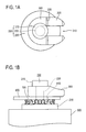
- Fig. 1A is a plan view showing a terminal 200 used for a connection mechanism of the present invention and a cam block 300 attached to the terminal 200.
- Fig. 1B is a side view showing a configuration of the connection mechanism.
- the connection mechanism is a mechanism which connects the terminal 200 attached to an electrical part 900 and a bus bar 800 having a bus bar hole 810.
- the terminal 200 secured to the electrical part 900 by soldering or welding or integrally formed as a part of the electrical part includes, as shown in a side view in Fig.
- a conductor-connecting washer 100, the bus bar 800, and the cam block 300 are arranged in order in the direction from the terminal base portion 230 to the terminal head 210, and the shaft 220 penetrates a washer hole 130 (see Fig. 4A ) of the conductor-connecting washer 100, the bus bar hole 810, and a slot 310 of the cam block 300.
- the cam block 300 gives pressing force to hold the conductor-connecting washer 100 between the bus bar 800 and the terminal base portion 230.
- the diameters of the bus bar hole 810 and the washer hole 130 are larger than the diameter of the terminal head 210.
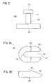
- Figs. 3A and 3B show the structure of the cam block 300.
- Fig. 3A is a plan view
- Fig. 3B is a side view.
- the cam block 300 is U-shaped.
- the width of the slot 310 formed between two arms of the U-shape is larger than the diameter of the shaft 220 and smaller than the diameter of the terminal head 210.
- the thickness of the cam block 300 on an open end 311 side is a thickness which enables the shaft 220 to be inserted to the slot 310 in a state where the conductor-connecting washer 100 and the bus bar 800 are attached to the shaft 220.
- the thickness of the cam block 300 on the open end side is smaller than the difference between a sum of the thickness of the conductor-connecting washer 100 when not pressured and the thickness of the bus bar 800 and the length of the shaft 220 (distance between the terminal base portion 230 and the terminal head 210).
- the two arms of the cam block 300 is formed with an inclination surface 320 such that the thickness increases towards a closed end 312 side of the slot 310.
- the thickness of the cam block 300 on the closed end 312 side of the slot 310 has a thickness in a state where the conductor-connecting washer 100 is sandwiched between the terminal base portion 230 and the bus bar 800 when the shaft 220 is inserted up to the closed end 312 of the slot 310.
- the thickness of the cam block 300 on the closed end 312 side is larger than the difference described earlier.
- a reversal preventing hill 330 is formed at the end of the inclination surface 320 of the cam block 300 on the closed end 312 side.
- a portion formed with the reversal preventing hill 330 is thicker than a portion of the closed end 312 of the slot 310.
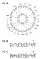
- Figs. 4A, 4B, and 4C are views showing the structure of the conductor-connecting washer.
- Fig. 4A is a plan view
- Fig. 4B is a side view
- Fig. 4C is a sectional view along line 4C-4C in Fig. 4A .
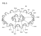
- Fig. 5 is a perspective view of the conductor-connecting washer.
- the washer hole 130 which is defined by a circle circumscribing the contact protrusions 123-m and 124-m formed along the inner circumference of the hole is larger than the diameter of the terminal head 210 and smaller than the outer shape of a curved portion of the cam block 300.
- the bus bar hole 810 is also larger than the diameter of the terminal head 210 and smaller than the outer shape of the conductor-connecting washer 100. However, if a slot is formed by cutting the bus bar 800 and the conductor-connecting washer 100 from the end side in place of the bus bar hole 810 and the washer hole 130 as in a modification described later, the width of the slot may be smaller than the diameter of the terminal head 210 as long as the shaft 220 can be passed through.
- the conductor-connecting washer 100 desirably has a close conductivity to pure copper in terms of reducing the contact resistance.
- using copper alloy which is harder than the bus bar 800 and the terminal 200 makes it easy to reduce the contact resistance since the contact protrusion bites into a conductor surface of the bus bar 800 and the terminal base portion 230.
- increasing the hardness of the copper alloy reduces the conductivity.
- copper alloy having a conductivity of 30% to 50% of pure copper is preferably used as the conductor-connecting washer 100.
- copper alloy having a conductivity of approximately 40% of pure copper exhibits favorable properties in terms of conductivity and in terms of mechanical characteristics (hardness and degree of elasticity).
- the contact protrusions 121-n and 122-n and the contact protrusions 123-m and 124-m are provided alternately along the outer circumference and the inner circumference, respectively.
- the contact protrusions may be formed on both surfaces from the same positions of the plate portion 110 (two-dimensional positions along the surface of the plate). Nonetheless, forming such protrusions on both surfaces from one position requires forging or cutting a block instead of pressing, and therefore is hardly practical.
- the protrusions are formed alternately along the outer circumference and the inner circumference of the plate portion 110 as in Fig.
- the conductor-connecting washer 100 can be manufactured easily by stripping from one conductive plate.
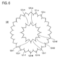
- Fig. 6 is a plan view showing the conductor-connecting washer being in a flattened state (so that the direction of the protrusion lies in a plane in which the surface of the plate extends). Specifically, manufacturing is easily done through a stripping step S151, a first protrusion forming step S152, a reversing step S153, and a second protrusion forming step S 154.
- a developed washer 100' in which the plate portion 110 and the contact protrusions 121-n, 122-n, 123-m, and 124-m are formed integrally in a state where the directions of all of the contact protrusions 121-n, 122-n, 123-m, and 124-m lie in the surface of the plate portion 110 is formed by cutting one conductive plate.
- the contact protrusions 121-n and 123-m on one surface of the plate portion 110 are formed by bending the contact protrusions 121-n and 123-m which are part of the developed washer member 100'.
- the developed washer member 100' of which the contact protrusions are formed on one surface is reversed.
- the contact protrusions 122-n and 124-m which have not been bent in the first protrusion forming step are bent toward the other surface side of the plate portion 110.
- the conductor-connecting washer shown in Fig. 4A can be manufactured easily with such a method.
- tips of the contact protrusions 121-n, 122-n, 123-m, and 124-m are formed through the stripping step S 151 and thus can be made sharp.
- the front end angle of each contact protrusion is preferably 50 to 70 degrees.
- the contact protrusions are preferably bent at an angle greater than 60 degrees and smaller than 90 degrees with respect to the plate portion 110.
- Fig. 7 is a sectional view of a state where the conductor-connecting washer is sandwiched between the bus bar 800 and the terminal base portion 230.
- an angle ⁇ between the direction of the contact protrusions 121-n, 122-n, 123-m, and 124-m (denoted collectively by reference numeral 120 in Fig. 7 ) and the surface of the plate portion 110 is smaller than 90 degrees as described above, the contact protrusions 121-n, 122-n, 123-m, and 124-m wipe the surface of the terminal base portion 230 or the bus bar 800 depending on the applied load and bite in further than in the case of 90 degrees.
- a favorable contact is easily achieved.
- the angle ⁇ between the direction of the contact protrusions 121-n, 122-n, 123-m, and 124-m and the surface of the plate portion 110 is desirably greater than 60 degrees.
- each contact protrusion of the conductor-connecting washer 100 described above is tapered such that contact with the terminal base portion 230 is made at a single point.
- two tapered contact sections 120a and 120b may be formed by dividing a front end section into two such that contact with the terminal base portion 230 is made at two points, as shown with the front end of one contact protrusion 120 in Fig. 8 .
- the two contact sections 120a and 120b may be formed to be flush with one another or may be formed by further bending one toward the inside in the radial direction of the conductor-connecting washer 100 so that two contact points are displaced in the radial direction.
- the structure of the contact protrusion in Fig. 8 may be applied in the modification described below.
- the conductor-connecting washer of the present invention includes the contact protrusions as described above, electrical connection can be made reliably with smaller load than when surfaces contact each other. Also, since the contact protrusions are arranged along the outer circumference and the inner circumference in consideration of the property of current concentrating at edges, current can flow efficiently with a small number of contact protrusions. That is, since the number of the contact protrusions can be reduced, the electrical connection can be made reliably with further smaller load than when a contact protrusion is provided in a simple manner. Thus, with the conductor-connecting washer of the present invention, two conductors can be electrically connected easily and reliably with low contact resistance. Also, since a small load would suffice, a stable connection can be ensured even with a pressure mechanism using a cam block.
- connection mechanism of the present invention is a mechanism suitable for the conductor-connecting washer of the present invention and has a structure in which the conductor-connecting washer is sandwiched between the bus bar and the terminal using the cam block. Thus, the bus bar and the terminal can be connected easily.
- a method of manufacturing a conductor-connecting washer of the present invention is a method of manufacturing the conductor-connecting washer of the present invention from one conductive plate, and the conductor-connecting washer can be manufactured with a simple process.
- connection mechanism may apply thread-tightening for pressing without the use of a cam, as shown in Fig. 9 . That is, in this modification, a thread 240 which functions as a shaft is integrally formed perpendicularly from the terminal base portion 230 of a terminal 200', the thread 240 is inserted through the conductor-connecting washer 100 and the bus bar 800, and a nut 250 which functions as a terminal head presses a washer 260 from above the bus bar 800.
- Fig. 10 is a plan view of the conductor-connecting washer according to a modification in a flattened state.
- the conductor-connecting washer 100 includes a connection section 151.
- One end of the connection section 151 is secured to the outer circumference of the plate portion 110.
- the connection section 151 is means for connecting a part different from the terminal base portion with which the contact protrusions 121-n, 122-n, 123-m, and 124-m contact.
- the connection section 151 can be used as a crimp terminal for connection with another electrical circuit. Providing the connection section in this manner is convenient for measurement of voltage or the like.
- the conductor-connecting washer of this modification can be made by bending the contact protrusion in Fig. 10 .
- Fig. 11 shows the conductor-connecting washer 100 according to another modification.
- the outer circumference forms a hexagon instead of a circle, and the contact protrusions are formed along each side of the hexagon. Otherwise, it is the same as in Fig. 4A .
- the outer circumference is not limited to a hexagon and may be an arbitrary polygon. However, a regular polygon having 5 or more sides is preferable.
- Fig. 12 shows another modification of the conductor-connecting washer 100.
- the difference from Fig. 4A is that the inner circumference of the washer hole 130 in the middle is not closed and a slot 160 is formed as a cutout having the same width as the diameter of the washer hole 130 from the middle up to the outer circumference of the conductor-connecting washer 100.
- the diameter of the washer hole 130 can be made larger than the diameter of the shaft 220 and smaller than the diameter of the terminal head 210.
- a slot may be formed also in the conductor-connecting washer 100 shown in Fig. 11 in a similar manner as in Fig. 12 as a cutout having a width which is the same as the diameter of the washer hole 130 from the washer hole 130 up to one side of a polygon.
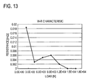
- Fig. 13 is a result of measuring the relationships between the clamp load and the contact resistance when two bus bars are directly tightened with threads. This shows that the resistance tends to be smaller with larger load.
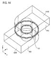
- Fig. 14 shows the configuration of two bus bars 810 and 820 and the conductor-connecting washer 100 used for simulation. The two bus bars 810 and 820 are in a state holding the conductor-connecting washer 100 in between. In an example in this drawing, the numbers of upper and lower contact protrusions are respectively 20.
- equipotential lines show the distribution of voltage when a vertical surface 820B of the bus bar 820 is 1 V and a vertical surface 810B of the bus bar 810 is 0 V. Such distribution of voltage was analyzed to obtain the contact resistance.
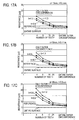
- Figs. 16A, 16B, and 16C are graphs each showing results obtained from simulation to determine the relationships between a resistance value and the number of contact protrusions (expressed as “number of teeth” in the drawings) on one surface when the diameter ( ⁇ ) of the conductor-connecting washer 100 is 12 mm.
- Figs. 17A, 17B, and 17C are graphs each showing the relationships between the resistance value and the number of contact protrusions (number of teeth) on one surface when the diameter ( ⁇ ) of the conductor-connecting washer is 18 mm as results of simulation in a similar manner.
- Figs. 16A and 17A show a case where the thickness (t) of the plate portion 110 is 0.5 mm
- 16B and 17B show a case where the thickness (t) of the plate portion 110 is 0.4 mm
- Figs. 16C and 17C show a case where the thickness (t) of the plate portion 110 is 0.3 mm.
- h refers to the length of the contact protrusion
- line “entire surface” refers to the contact resistance when the bus bars 810 and 820 are caused to contact each other on the entire surface
- line “reference” shows a value 1.5 times that of the case of entire surface contact, which is where the resistance value becomes stable (becomes linear).
- the total area of contacts of the bus bars 810 and 820 is made the same for any of the numbers of teeth.
- the number of teeth being 24 shows a case where 16 contact protrusions are provided on the outer circumference and 8 on the inner circumference.
- the 16 contact protrusions on the outer circumference are the same as when the number of teeth is 16. That is, when the number of teeth is 24, the area of contact with the bus bars 810 and 820 also increases.
- the resistance value shown in at the rightmost position (position where the number of teeth is supposed to be 100) in each graph shows a case where a ring-shaped protrusion is provided with a width equivalent to the thickness of the plate only on the outer circumference (a case where the entire outer circumference is in contact).
- the area of the bus bars 810 and 820 in contact at this time is twice that of when the number of teeth is 16.
- the entire surface contact in this simulation produces a result for a case of an ideal entire surface contact.
- the contact resistance obtained from actual measurement is expected to be approximately the resistance value shown by the reference.
- the entire surface contact can produce a contact resistance close to when load is applied by thread-tightening or the like.
- the present invention can be used for connection of conductors where a relatively large amount of current flows.
Landscapes
- Chemical & Material Sciences (AREA)
- Chemical Kinetics & Catalysis (AREA)
- Electrochemistry (AREA)
- General Chemical & Material Sciences (AREA)
- Inorganic Chemistry (AREA)
- Connections By Means Of Piercing Elements, Nuts, Or Screws (AREA)
- Connection Of Batteries Or Terminals (AREA)
- Manufacturing Of Electrical Connectors (AREA)
- Installation Of Bus-Bars (AREA)
- Coupling Device And Connection With Printed Circuit (AREA)
Applications Claiming Priority (2)
| Application Number | Priority Date | Filing Date | Title |
|---|---|---|---|
| JP2010118277 | 2010-05-24 | ||
| JP2011037975A JP2012009411A (ja) | 2010-05-24 | 2011-02-24 | 導体接続ワッシャ、それを使った接続機構及び導体接続ワッシャの製造方法 |
Publications (3)
| Publication Number | Publication Date |
|---|---|
| EP2390946A2 EP2390946A2 (en) | 2011-11-30 |
| EP2390946A3 EP2390946A3 (en) | 2012-01-11 |
| EP2390946B1 true EP2390946B1 (en) | 2013-06-19 |
Family
ID=44246530
Family Applications (1)
| Application Number | Title | Priority Date | Filing Date |
|---|---|---|---|
| EP11161826.0A Not-in-force EP2390946B1 (en) | 2010-05-24 | 2011-04-11 | Conductor-connecting washer, connection mechanism using the same, and method of manufacturing conductor-connecting washer |
Country Status (5)
| Country | Link |
|---|---|
| US (1) | US8303357B2 (enExample) |
| EP (1) | EP2390946B1 (enExample) |
| JP (1) | JP2012009411A (enExample) |
| KR (1) | KR101238188B1 (enExample) |
| CN (1) | CN102332644A (enExample) |
Families Citing this family (45)
| Publication number | Priority date | Publication date | Assignee | Title |
|---|---|---|---|---|
| US8092129B2 (en) * | 2006-04-21 | 2012-01-10 | Hubbell Incorporated | Bonding washer |
| DE102011014342A1 (de) * | 2011-03-18 | 2012-09-20 | GM Global Technology Operations LLC (n. d. Gesetzen des Staates Delaware) | Kabelschuh für ein Verbinden eines elektrischen Kabels mit einer Komponente eines Kraftfahrzeugs |
| US8572909B2 (en) * | 2011-03-24 | 2013-11-05 | Solar Mounting Solutions, LLC | Flat roof solar racking system |
| WO2013033687A1 (en) | 2011-09-02 | 2013-03-07 | Rtetta Holdings, Llc | System for tracking and allocating renewable energy contributions to a modular renewable energy system |
| US10008974B2 (en) | 2011-09-02 | 2018-06-26 | Pv Solutions, Llc | Mounting system for photovoltaic arrays |
| US11022343B2 (en) | 2011-09-02 | 2021-06-01 | Pv Solutions, Llc | Mounting system for photovoltaic arrays |
| US9362634B2 (en) * | 2011-12-27 | 2016-06-07 | Perfectvision Manufacturing, Inc. | Enhanced continuity connector |
| US20130316601A1 (en) * | 2012-05-24 | 2013-11-28 | Cablofil, Inc. | Bonding clip |
| US8997336B2 (en) * | 2012-09-10 | 2015-04-07 | Renewable Energy Holdings, Llc | Air-tight and water-tight electrical bonding device |
| CN203232920U (zh) * | 2012-12-25 | 2013-10-09 | 华广生技股份有限公司 | 电池导电片及具有可活动式电池导电片的电子装置 |
| JP6012575B2 (ja) * | 2012-12-19 | 2016-10-25 | 三菱重工業株式会社 | 電池状態監視装置及びこれを備えた電池モジュール |
| JP5766683B2 (ja) | 2012-12-21 | 2015-08-19 | 三菱重工業株式会社 | 電池状態監視装置及びこれを備えた電池モジュール |
| US9847521B2 (en) | 2012-12-25 | 2017-12-19 | Bionime Corporation | Conductive plate and an electronic device having the same |
| US9653194B2 (en) * | 2013-08-12 | 2017-05-16 | Te Connectivity Corporation | Low resistance insert |
| WO2015052955A1 (ja) * | 2013-10-09 | 2015-04-16 | 三菱電機株式会社 | 導体接続構造およびこれを用いたスイッチギヤ |
| US9276521B2 (en) | 2014-01-16 | 2016-03-01 | JSI Equipment Solutions LLC | Clamp for solar panel array |
| US9520657B2 (en) * | 2014-07-31 | 2016-12-13 | Hubbell Incorporated | Electrical terminal |
| US10177401B2 (en) * | 2014-11-20 | 2019-01-08 | Qualcomm Incorporated | Method of establishing physical and electrical connections between a battery and a circuit |
| WO2016123357A2 (en) | 2015-01-28 | 2016-08-04 | Pv Solutions, Llc | Integrated electrical and mechanical photovoltaic array interconnection system |
| US10103468B2 (en) | 2015-03-06 | 2018-10-16 | Kd&E Solar, Llc. | Coating displacement electrical connecting device and related methods |
| USD782409S1 (en) | 2015-03-30 | 2017-03-28 | Johnson Controls Technology Company | Lithium ion battery cell with terminal washers |
| AU2016366320A1 (en) * | 2015-12-09 | 2018-07-12 | Hubbell Incorporated | Bonding clamp |
| JP2017188386A (ja) * | 2016-04-08 | 2017-10-12 | 株式会社オートネットワーク技術研究所 | 電気的接続構造 |
| USD832220S1 (en) | 2017-05-10 | 2018-10-30 | Xerox Corporation | Earth plate |
| USD823262S1 (en) * | 2017-05-10 | 2018-07-17 | Xerox Corporation | Earth plate |
| US10175631B2 (en) | 2017-05-10 | 2019-01-08 | Xerox Corporation | Earth plate with breakaway rotated tabs |
| USD867435S1 (en) | 2018-07-04 | 2019-11-19 | Innovelis, Inc. | Mount for electronic devices |
| JP6653295B2 (ja) * | 2017-08-03 | 2020-02-26 | 矢崎総業株式会社 | バスバモジュールの電極接触構造 |
| US11149775B2 (en) * | 2017-11-22 | 2021-10-19 | Penn Engineering & Manufacturing Corp. | Easily removeable push-on spring nut |
| USD865727S1 (en) * | 2018-06-21 | 2019-11-05 | Innovelis, Inc. | Mount for electronic devices |
| FR3085794B1 (fr) * | 2018-09-12 | 2020-11-13 | Commissariat Energie Atomique | Pack-batterie d'accumulateurs electrochimiques comprenant des dispositifs de deconnexion magnetique passive entre les accumulateurs et des busbars, et le cas echeant de shunt passif d'un ou plusieurs accumulateurs en cas de defaillance d'un de ceux-ci |
| USD905068S1 (en) | 2019-05-09 | 2020-12-15 | Innovelis, Inc. | Mount for electronic devices |
| USD905069S1 (en) | 2019-05-09 | 2020-12-15 | Innovelis, Inc. | Mount for electronic devices |
| USD905067S1 (en) | 2019-05-09 | 2020-12-15 | Innovelis, Inc. | Mount for electronic devices |
| CN111916926B (zh) * | 2019-05-09 | 2025-02-11 | 博格华纳公司 | 电连接器和包括其的控制阀 |
| DE102020210534B4 (de) | 2020-04-30 | 2023-03-23 | Te Connectivity Germany Gmbh | Kontaktsystem |
| CN113594742A (zh) * | 2020-04-30 | 2021-11-02 | 泰连德国有限公司 | 接触环和接触系统 |
| KR20220014041A (ko) * | 2020-07-28 | 2022-02-04 | 주식회사 엘지에너지솔루션 | 기계적 및 전기적 연결을 위한 모재 조립체 및 이의 리벳팅 방법 |
| DE102020130634A1 (de) * | 2020-11-19 | 2022-05-19 | Te Connectivity Germany Gmbh | Kontaktring für hochdynamische anwendungen |
| CN114976580A (zh) * | 2021-02-22 | 2022-08-30 | 北京小米移动软件有限公司 | 天线安装结构及电子设备 |
| US11522303B1 (en) * | 2021-06-14 | 2022-12-06 | Te Connectivity Solutions Gmbh | Terminal post assembly for termination of electrical terminals without the need for tooling |
| US12237658B2 (en) * | 2021-07-29 | 2025-02-25 | Aptiv Technologies AG | Bus bar assembly with plated electrical contact surface |
| KR102789584B1 (ko) * | 2023-03-16 | 2025-04-01 | 주식회사 엘라인 | 도전성 조립체 및 그 조립방법 |
| US12246183B1 (en) * | 2023-10-06 | 2025-03-11 | Greatbatch Ltd. | Self-centering polymeric washer that prevents misalignment when positioned between a feedthrough and a circuit board supporting EMI filter capacitors for a medical device |
| US12385514B1 (en) | 2024-02-09 | 2025-08-12 | Heico Befestigungstechnik Gmbh | Wedge lock washer pair and tensioning arrangement with such wedge lock washer pair |
Family Cites Families (22)
| Publication number | Priority date | Publication date | Assignee | Title |
|---|---|---|---|---|
| US1150745A (en) * | 1915-04-30 | 1915-08-17 | Thomas Washington Crozier | Nut-locking washer. |
| US1847689A (en) * | 1929-02-02 | 1932-03-01 | Shakeproof Lock Washer Co | Electrical connecter |
| US1911384A (en) * | 1930-07-14 | 1933-05-30 | Shakeproof Lock Washer Co | Lock washer |
| US1882089A (en) * | 1930-09-02 | 1932-10-11 | Shakeproof Lock Washer Co | Lock washer |
| US2559833A (en) | 1948-12-31 | 1951-07-10 | Domnic V Stellin | Lock washer |
| FR1586636A (enExample) | 1968-02-29 | 1970-02-27 | ||
| US4060301A (en) * | 1974-03-12 | 1977-11-29 | Beatty Albert W | Electrical connector for transmission line insulators |
| JPS57164317U (enExample) * | 1981-04-09 | 1982-10-16 | ||
| JPH0134287Y2 (enExample) * | 1985-05-17 | 1989-10-18 | ||
| KR900003350Y1 (ko) * | 1986-06-07 | 1990-04-20 | 금성기전 주식회사 | 풀림 방지 나사 |
| JPS63259978A (ja) * | 1987-04-16 | 1988-10-27 | 三菱電機株式会社 | 圧着端子 |
| DE19600417A1 (de) | 1996-01-08 | 1997-07-17 | Sefag Ag | Kontaktelement sowie Anschlußvorrichtung mit diesem Kontaktelement |
| JP3533637B2 (ja) * | 1999-09-29 | 2004-05-31 | 日本電気エンジニアリング株式会社 | 電子機器の接地構造 |
| JP2004253311A (ja) * | 2003-02-21 | 2004-09-09 | Toyota Motor Corp | 電気接続部材及び電気接続部材の接続方法並びに組電池 |
| JP4274014B2 (ja) | 2004-03-18 | 2009-06-03 | 日産自動車株式会社 | 導電部材および組電池 |
| JP3897029B2 (ja) | 2004-03-30 | 2007-03-22 | 日産自動車株式会社 | 組電池用フレームおよび組電池 |
| JP4543310B2 (ja) | 2004-05-17 | 2010-09-15 | 株式会社デンソー | 電極の接合方法及び電極接合体 |
| KR100696670B1 (ko) * | 2005-09-05 | 2007-03-19 | 삼성에스디아이 주식회사 | 이차 전지 모듈 |
| US8092129B2 (en) * | 2006-04-21 | 2012-01-10 | Hubbell Incorporated | Bonding washer |
| JP5189758B2 (ja) | 2006-11-30 | 2013-04-24 | 日産自動車株式会社 | 双極型電池の製造装置および製造方法 |
| KR200438876Y1 (ko) | 2007-05-14 | 2008-03-07 | 이승철 | 절연파괴와셔 |
| EP2324521A4 (en) | 2008-09-09 | 2013-10-23 | Johnson Controls Saft Advanced | WASHER INTERCONNECTION ASSEMBLY FOR BATTERY MODULE |
-
2011
- 2011-02-24 JP JP2011037975A patent/JP2012009411A/ja active Pending
- 2011-03-30 KR KR1020110028724A patent/KR101238188B1/ko not_active Expired - Fee Related
- 2011-04-08 US US13/083,518 patent/US8303357B2/en not_active Expired - Fee Related
- 2011-04-11 EP EP11161826.0A patent/EP2390946B1/en not_active Not-in-force
- 2011-04-11 CN CN2011101446834A patent/CN102332644A/zh active Pending
Also Published As
| Publication number | Publication date |
|---|---|
| US20110287644A1 (en) | 2011-11-24 |
| KR20110128729A (ko) | 2011-11-30 |
| EP2390946A3 (en) | 2012-01-11 |
| US8303357B2 (en) | 2012-11-06 |
| EP2390946A2 (en) | 2011-11-30 |
| JP2012009411A (ja) | 2012-01-12 |
| KR101238188B1 (ko) | 2013-02-28 |
| CN102332644A (zh) | 2012-01-25 |
Similar Documents
| Publication | Publication Date | Title |
|---|---|---|
| EP2390946B1 (en) | Conductor-connecting washer, connection mechanism using the same, and method of manufacturing conductor-connecting washer | |
| US6911602B2 (en) | Connecting terminal | |
| EP2343755A1 (en) | Secondary battery busbar and secondary battery module | |
| EP2698876A1 (en) | Terminal fitting and connection method therefor | |
| WO2010024033A1 (ja) | 端子金具及び端子金具の製造方法 | |
| US9543679B2 (en) | Electrical contact assembly | |
| WO2017175622A1 (ja) | 電気的接続構造 | |
| WO2020054390A1 (ja) | 接続端子及びコネクタ | |
| JP6148841B2 (ja) | ワッシャ | |
| JP5100847B2 (ja) | 接続装置及びそれを用いたコントロ−ルセンタ | |
| WO2012018064A1 (ja) | 電気的接続構造 | |
| JP5170736B2 (ja) | バスバー | |
| CN104823329A (zh) | 用于建立电线路与导电构件之间的导电连接的方法以及根据该方法制造的结构组合件 | |
| JP2014053244A (ja) | 接続部材 | |
| US9780464B2 (en) | Connector with clamp element | |
| JP2011070847A (ja) | バスバーへの溶接構造、およびバスバーへの溶接方法 | |
| JP5151936B2 (ja) | 端子金具及びその製造方法 | |
| WO2015053182A1 (ja) | 圧着端子 | |
| JP5989255B2 (ja) | 導体接続構造およびこれを用いたスイッチギヤ | |
| JP5838938B2 (ja) | 端子付き電線 | |
| CN110892585B (zh) | 电插塞连接器和插塞连接器系统 | |
| JP7413967B2 (ja) | プレスフィット端子及びコネクタ装置 | |
| JP7144286B2 (ja) | 電線及び電線束 | |
| CN112997363A (zh) | 用于无螺纹连接端子的夹持弹簧 | |
| JP2020161469A (ja) | 電子装置及び圧接端子 |
Legal Events
| Date | Code | Title | Description |
|---|---|---|---|
| 17P | Request for examination filed |
Effective date: 20110411 |
|
| AK | Designated contracting states |
Kind code of ref document: A2 Designated state(s): AL AT BE BG CH CY CZ DE DK EE ES FI FR GB GR HR HU IE IS IT LI LT LU LV MC MK MT NL NO PL PT RO RS SE SI SK SM TR |
|
| AX | Request for extension of the european patent |
Extension state: BA ME |
|
| PUAI | Public reference made under article 153(3) epc to a published international application that has entered the european phase |
Free format text: ORIGINAL CODE: 0009012 |
|
| PUAL | Search report despatched |
Free format text: ORIGINAL CODE: 0009013 |
|
| AK | Designated contracting states |
Kind code of ref document: A3 Designated state(s): AL AT BE BG CH CY CZ DE DK EE ES FI FR GB GR HR HU IE IS IT LI LT LU LV MC MK MT NL NO PL PT RO RS SE SI SK SM TR |
|
| AX | Request for extension of the european patent |
Extension state: BA ME |
|
| RIC1 | Information provided on ipc code assigned before grant |
Ipc: H01M 2/20 20060101AFI20111208BHEP Ipc: H01R 4/26 20060101ALI20111208BHEP |
|
| RIC1 | Information provided on ipc code assigned before grant |
Ipc: H01R 4/24 20060101ALI20120807BHEP Ipc: H01M 2/20 20060101AFI20120807BHEP |
|
| GRAP | Despatch of communication of intention to grant a patent |
Free format text: ORIGINAL CODE: EPIDOSNIGR1 |
|
| RIN1 | Information on inventor provided before grant (corrected) |
Inventor name: ISHIYAMA, YOSHIAKI Inventor name: KUWAHARA, TAKASHI |
|
| GRAS | Grant fee paid |
Free format text: ORIGINAL CODE: EPIDOSNIGR3 |
|
| GRAA | (expected) grant |
Free format text: ORIGINAL CODE: 0009210 |
|
| AK | Designated contracting states |
Kind code of ref document: B1 Designated state(s): AL AT BE BG CH CY CZ DE DK EE ES FI FR GB GR HR HU IE IS IT LI LT LU LV MC MK MT NL NO PL PT RO RS SE SI SK SM TR |
|
| REG | Reference to a national code |
Ref country code: GB Ref legal event code: FG4D |
|
| REG | Reference to a national code |
Ref country code: CH Ref legal event code: EP |
|
| REG | Reference to a national code |
Ref country code: AT Ref legal event code: REF Ref document number: 618082 Country of ref document: AT Kind code of ref document: T Effective date: 20130715 |
|
| REG | Reference to a national code |
Ref country code: IE Ref legal event code: FG4D |
|
| REG | Reference to a national code |
Ref country code: DE Ref legal event code: R096 Ref document number: 602011002052 Country of ref document: DE Effective date: 20130814 |
|
| PG25 | Lapsed in a contracting state [announced via postgrant information from national office to epo] |
Ref country code: ES Free format text: LAPSE BECAUSE OF FAILURE TO SUBMIT A TRANSLATION OF THE DESCRIPTION OR TO PAY THE FEE WITHIN THE PRESCRIBED TIME-LIMIT Effective date: 20130930 Ref country code: FI Free format text: LAPSE BECAUSE OF FAILURE TO SUBMIT A TRANSLATION OF THE DESCRIPTION OR TO PAY THE FEE WITHIN THE PRESCRIBED TIME-LIMIT Effective date: 20130619 Ref country code: GR Free format text: LAPSE BECAUSE OF FAILURE TO SUBMIT A TRANSLATION OF THE DESCRIPTION OR TO PAY THE FEE WITHIN THE PRESCRIBED TIME-LIMIT Effective date: 20130920 Ref country code: SE Free format text: LAPSE BECAUSE OF FAILURE TO SUBMIT A TRANSLATION OF THE DESCRIPTION OR TO PAY THE FEE WITHIN THE PRESCRIBED TIME-LIMIT Effective date: 20130619 Ref country code: LT Free format text: LAPSE BECAUSE OF FAILURE TO SUBMIT A TRANSLATION OF THE DESCRIPTION OR TO PAY THE FEE WITHIN THE PRESCRIBED TIME-LIMIT Effective date: 20130619 Ref country code: NO Free format text: LAPSE BECAUSE OF FAILURE TO SUBMIT A TRANSLATION OF THE DESCRIPTION OR TO PAY THE FEE WITHIN THE PRESCRIBED TIME-LIMIT Effective date: 20130919 Ref country code: SI Free format text: LAPSE BECAUSE OF FAILURE TO SUBMIT A TRANSLATION OF THE DESCRIPTION OR TO PAY THE FEE WITHIN THE PRESCRIBED TIME-LIMIT Effective date: 20130619 |
|
| REG | Reference to a national code |
Ref country code: AT Ref legal event code: MK05 Ref document number: 618082 Country of ref document: AT Kind code of ref document: T Effective date: 20130619 |
|
| REG | Reference to a national code |
Ref country code: LT Ref legal event code: MG4D |
|
| PG25 | Lapsed in a contracting state [announced via postgrant information from national office to epo] |
Ref country code: RS Free format text: LAPSE BECAUSE OF FAILURE TO SUBMIT A TRANSLATION OF THE DESCRIPTION OR TO PAY THE FEE WITHIN THE PRESCRIBED TIME-LIMIT Effective date: 20130619 Ref country code: HR Free format text: LAPSE BECAUSE OF FAILURE TO SUBMIT A TRANSLATION OF THE DESCRIPTION OR TO PAY THE FEE WITHIN THE PRESCRIBED TIME-LIMIT Effective date: 20130619 Ref country code: BG Free format text: LAPSE BECAUSE OF FAILURE TO SUBMIT A TRANSLATION OF THE DESCRIPTION OR TO PAY THE FEE WITHIN THE PRESCRIBED TIME-LIMIT Effective date: 20130919 |
|
| REG | Reference to a national code |
Ref country code: NL Ref legal event code: VDEP Effective date: 20130619 |
|
| PG25 | Lapsed in a contracting state [announced via postgrant information from national office to epo] |
Ref country code: LV Free format text: LAPSE BECAUSE OF FAILURE TO SUBMIT A TRANSLATION OF THE DESCRIPTION OR TO PAY THE FEE WITHIN THE PRESCRIBED TIME-LIMIT Effective date: 20130619 |
|
| PG25 | Lapsed in a contracting state [announced via postgrant information from national office to epo] |
Ref country code: CZ Free format text: LAPSE BECAUSE OF FAILURE TO SUBMIT A TRANSLATION OF THE DESCRIPTION OR TO PAY THE FEE WITHIN THE PRESCRIBED TIME-LIMIT Effective date: 20130619 Ref country code: EE Free format text: LAPSE BECAUSE OF FAILURE TO SUBMIT A TRANSLATION OF THE DESCRIPTION OR TO PAY THE FEE WITHIN THE PRESCRIBED TIME-LIMIT Effective date: 20130619 Ref country code: IS Free format text: LAPSE BECAUSE OF FAILURE TO SUBMIT A TRANSLATION OF THE DESCRIPTION OR TO PAY THE FEE WITHIN THE PRESCRIBED TIME-LIMIT Effective date: 20131019 Ref country code: CY Free format text: LAPSE BECAUSE OF FAILURE TO SUBMIT A TRANSLATION OF THE DESCRIPTION OR TO PAY THE FEE WITHIN THE PRESCRIBED TIME-LIMIT Effective date: 20130731 Ref country code: AT Free format text: LAPSE BECAUSE OF FAILURE TO SUBMIT A TRANSLATION OF THE DESCRIPTION OR TO PAY THE FEE WITHIN THE PRESCRIBED TIME-LIMIT Effective date: 20130619 Ref country code: SK Free format text: LAPSE BECAUSE OF FAILURE TO SUBMIT A TRANSLATION OF THE DESCRIPTION OR TO PAY THE FEE WITHIN THE PRESCRIBED TIME-LIMIT Effective date: 20130619 Ref country code: PT Free format text: LAPSE BECAUSE OF FAILURE TO SUBMIT A TRANSLATION OF THE DESCRIPTION OR TO PAY THE FEE WITHIN THE PRESCRIBED TIME-LIMIT Effective date: 20131021 Ref country code: BE Free format text: LAPSE BECAUSE OF FAILURE TO SUBMIT A TRANSLATION OF THE DESCRIPTION OR TO PAY THE FEE WITHIN THE PRESCRIBED TIME-LIMIT Effective date: 20130619 |
|
| PG25 | Lapsed in a contracting state [announced via postgrant information from national office to epo] |
Ref country code: PL Free format text: LAPSE BECAUSE OF FAILURE TO SUBMIT A TRANSLATION OF THE DESCRIPTION OR TO PAY THE FEE WITHIN THE PRESCRIBED TIME-LIMIT Effective date: 20130619 Ref country code: RO Free format text: LAPSE BECAUSE OF FAILURE TO SUBMIT A TRANSLATION OF THE DESCRIPTION OR TO PAY THE FEE WITHIN THE PRESCRIBED TIME-LIMIT Effective date: 20130619 Ref country code: NL Free format text: LAPSE BECAUSE OF FAILURE TO SUBMIT A TRANSLATION OF THE DESCRIPTION OR TO PAY THE FEE WITHIN THE PRESCRIBED TIME-LIMIT Effective date: 20130619 |
|
| PG25 | Lapsed in a contracting state [announced via postgrant information from national office to epo] |
Ref country code: CY Free format text: LAPSE BECAUSE OF FAILURE TO SUBMIT A TRANSLATION OF THE DESCRIPTION OR TO PAY THE FEE WITHIN THE PRESCRIBED TIME-LIMIT Effective date: 20130619 |
|
| PLBE | No opposition filed within time limit |
Free format text: ORIGINAL CODE: 0009261 |
|
| STAA | Information on the status of an ep patent application or granted ep patent |
Free format text: STATUS: NO OPPOSITION FILED WITHIN TIME LIMIT |
|
| PG25 | Lapsed in a contracting state [announced via postgrant information from national office to epo] |
Ref country code: DK Free format text: LAPSE BECAUSE OF FAILURE TO SUBMIT A TRANSLATION OF THE DESCRIPTION OR TO PAY THE FEE WITHIN THE PRESCRIBED TIME-LIMIT Effective date: 20130619 |
|
| 26N | No opposition filed |
Effective date: 20140320 |
|
| REG | Reference to a national code |
Ref country code: DE Ref legal event code: R097 Ref document number: 602011002052 Country of ref document: DE Effective date: 20140320 |
|
| PG25 | Lapsed in a contracting state [announced via postgrant information from national office to epo] |
Ref country code: LU Free format text: LAPSE BECAUSE OF FAILURE TO SUBMIT A TRANSLATION OF THE DESCRIPTION OR TO PAY THE FEE WITHIN THE PRESCRIBED TIME-LIMIT Effective date: 20140411 Ref country code: MC Free format text: LAPSE BECAUSE OF FAILURE TO SUBMIT A TRANSLATION OF THE DESCRIPTION OR TO PAY THE FEE WITHIN THE PRESCRIBED TIME-LIMIT Effective date: 20130619 |
|
| REG | Reference to a national code |
Ref country code: CH Ref legal event code: PL |
|
| REG | Reference to a national code |
Ref country code: IE Ref legal event code: MM4A |
|
| PG25 | Lapsed in a contracting state [announced via postgrant information from national office to epo] |
Ref country code: LI Free format text: LAPSE BECAUSE OF NON-PAYMENT OF DUE FEES Effective date: 20140430 Ref country code: CH Free format text: LAPSE BECAUSE OF NON-PAYMENT OF DUE FEES Effective date: 20140430 |
|
| REG | Reference to a national code |
Ref country code: FR Ref legal event code: PLFP Year of fee payment: 5 |
|
| PG25 | Lapsed in a contracting state [announced via postgrant information from national office to epo] |
Ref country code: IE Free format text: LAPSE BECAUSE OF NON-PAYMENT OF DUE FEES Effective date: 20140411 |
|
| PGFP | Annual fee paid to national office [announced via postgrant information from national office to epo] |
Ref country code: FR Payment date: 20150225 Year of fee payment: 5 |
|
| PGFP | Annual fee paid to national office [announced via postgrant information from national office to epo] |
Ref country code: DE Payment date: 20150430 Year of fee payment: 5 |
|
| PGFP | Annual fee paid to national office [announced via postgrant information from national office to epo] |
Ref country code: IT Payment date: 20150409 Year of fee payment: 5 |
|
| GBPC | Gb: european patent ceased through non-payment of renewal fee |
Effective date: 20150411 |
|
| PG25 | Lapsed in a contracting state [announced via postgrant information from national office to epo] |
Ref country code: GB Free format text: LAPSE BECAUSE OF NON-PAYMENT OF DUE FEES Effective date: 20150411 |
|
| PG25 | Lapsed in a contracting state [announced via postgrant information from national office to epo] |
Ref country code: MT Free format text: LAPSE BECAUSE OF FAILURE TO SUBMIT A TRANSLATION OF THE DESCRIPTION OR TO PAY THE FEE WITHIN THE PRESCRIBED TIME-LIMIT Effective date: 20130619 |
|
| PG25 | Lapsed in a contracting state [announced via postgrant information from national office to epo] |
Ref country code: SM Free format text: LAPSE BECAUSE OF FAILURE TO SUBMIT A TRANSLATION OF THE DESCRIPTION OR TO PAY THE FEE WITHIN THE PRESCRIBED TIME-LIMIT Effective date: 20130619 |
|
| PG25 | Lapsed in a contracting state [announced via postgrant information from national office to epo] |
Ref country code: HU Free format text: LAPSE BECAUSE OF FAILURE TO SUBMIT A TRANSLATION OF THE DESCRIPTION OR TO PAY THE FEE WITHIN THE PRESCRIBED TIME-LIMIT; INVALID AB INITIO Effective date: 20110411 Ref country code: TR Free format text: LAPSE BECAUSE OF FAILURE TO SUBMIT A TRANSLATION OF THE DESCRIPTION OR TO PAY THE FEE WITHIN THE PRESCRIBED TIME-LIMIT Effective date: 20130619 |
|
| REG | Reference to a national code |
Ref country code: DE Ref legal event code: R119 Ref document number: 602011002052 Country of ref document: DE |
|
| REG | Reference to a national code |
Ref country code: FR Ref legal event code: ST Effective date: 20161230 |
|
| PG25 | Lapsed in a contracting state [announced via postgrant information from national office to epo] |
Ref country code: FR Free format text: LAPSE BECAUSE OF NON-PAYMENT OF DUE FEES Effective date: 20160502 Ref country code: DE Free format text: LAPSE BECAUSE OF NON-PAYMENT OF DUE FEES Effective date: 20161101 |
|
| PG25 | Lapsed in a contracting state [announced via postgrant information from national office to epo] |
Ref country code: IT Free format text: LAPSE BECAUSE OF NON-PAYMENT OF DUE FEES Effective date: 20160411 |
|
| PG25 | Lapsed in a contracting state [announced via postgrant information from national office to epo] |
Ref country code: MK Free format text: LAPSE BECAUSE OF FAILURE TO SUBMIT A TRANSLATION OF THE DESCRIPTION OR TO PAY THE FEE WITHIN THE PRESCRIBED TIME-LIMIT Effective date: 20130619 |
|
| PG25 | Lapsed in a contracting state [announced via postgrant information from national office to epo] |
Ref country code: AL Free format text: LAPSE BECAUSE OF FAILURE TO SUBMIT A TRANSLATION OF THE DESCRIPTION OR TO PAY THE FEE WITHIN THE PRESCRIBED TIME-LIMIT Effective date: 20130619 |