EP2387666B1 - Fluid working machine and method of operating fluid working machine - Google Patents
Fluid working machine and method of operating fluid working machine Download PDFInfo
- Publication number
- EP2387666B1 EP2387666B1 EP11712288.7A EP11712288A EP2387666B1 EP 2387666 B1 EP2387666 B1 EP 2387666B1 EP 11712288 A EP11712288 A EP 11712288A EP 2387666 B1 EP2387666 B1 EP 2387666B1
- Authority
- EP
- European Patent Office
- Prior art keywords
- working
- fluid
- working chamber
- volume
- cycle
- Prior art date
- Legal status (The legal status is an assumption and is not a legal conclusion. Google has not performed a legal analysis and makes no representation as to the accuracy of the status listed.)
- Not-in-force
Links
Images



Classifications
-
- F—MECHANICAL ENGINEERING; LIGHTING; HEATING; WEAPONS; BLASTING
- F04—POSITIVE - DISPLACEMENT MACHINES FOR LIQUIDS; PUMPS FOR LIQUIDS OR ELASTIC FLUIDS
- F04B—POSITIVE-DISPLACEMENT MACHINES FOR LIQUIDS; PUMPS
- F04B49/00—Control, e.g. of pump delivery, or pump pressure of, or safety measures for, machines, pumps, or pumping installations, not otherwise provided for, or of interest apart from, groups F04B1/00 - F04B47/00
- F04B49/06—Control using electricity
- F04B49/065—Control using electricity and making use of computers
-
- F—MECHANICAL ENGINEERING; LIGHTING; HEATING; WEAPONS; BLASTING
- F03—MACHINES OR ENGINES FOR LIQUIDS; WIND, SPRING, OR WEIGHT MOTORS; PRODUCING MECHANICAL POWER OR A REACTIVE PROPULSIVE THRUST, NOT OTHERWISE PROVIDED FOR
- F03B—MACHINES OR ENGINES FOR LIQUIDS
- F03B15/00—Controlling
- F03B15/02—Controlling by varying liquid flow
-
- F—MECHANICAL ENGINEERING; LIGHTING; HEATING; WEAPONS; BLASTING
- F04—POSITIVE - DISPLACEMENT MACHINES FOR LIQUIDS; PUMPS FOR LIQUIDS OR ELASTIC FLUIDS
- F04B—POSITIVE-DISPLACEMENT MACHINES FOR LIQUIDS; PUMPS
- F04B1/00—Multi-cylinder machines or pumps characterised by number or arrangement of cylinders
- F04B1/04—Multi-cylinder machines or pumps characterised by number or arrangement of cylinders having cylinders in star- or fan-arrangement
- F04B1/06—Control
-
- F—MECHANICAL ENGINEERING; LIGHTING; HEATING; WEAPONS; BLASTING
- F03—MACHINES OR ENGINES FOR LIQUIDS; WIND, SPRING, OR WEIGHT MOTORS; PRODUCING MECHANICAL POWER OR A REACTIVE PROPULSIVE THRUST, NOT OTHERWISE PROVIDED FOR
- F03D—WIND MOTORS
- F03D15/00—Transmission of mechanical power
-
- F—MECHANICAL ENGINEERING; LIGHTING; HEATING; WEAPONS; BLASTING
- F03—MACHINES OR ENGINES FOR LIQUIDS; WIND, SPRING, OR WEIGHT MOTORS; PRODUCING MECHANICAL POWER OR A REACTIVE PROPULSIVE THRUST, NOT OTHERWISE PROVIDED FOR
- F03D—WIND MOTORS
- F03D9/00—Adaptations of wind motors for special use; Combinations of wind motors with apparatus driven thereby; Wind motors specially adapted for installation in particular locations
- F03D9/20—Wind motors characterised by the driven apparatus
- F03D9/25—Wind motors characterised by the driven apparatus the apparatus being an electrical generator
-
- F—MECHANICAL ENGINEERING; LIGHTING; HEATING; WEAPONS; BLASTING
- F04—POSITIVE - DISPLACEMENT MACHINES FOR LIQUIDS; PUMPS FOR LIQUIDS OR ELASTIC FLUIDS
- F04B—POSITIVE-DISPLACEMENT MACHINES FOR LIQUIDS; PUMPS
- F04B49/00—Control, e.g. of pump delivery, or pump pressure of, or safety measures for, machines, pumps, or pumping installations, not otherwise provided for, or of interest apart from, groups F04B1/00 - F04B47/00
- F04B49/06—Control using electricity
-
- F—MECHANICAL ENGINEERING; LIGHTING; HEATING; WEAPONS; BLASTING
- F04—POSITIVE - DISPLACEMENT MACHINES FOR LIQUIDS; PUMPS FOR LIQUIDS OR ELASTIC FLUIDS
- F04B—POSITIVE-DISPLACEMENT MACHINES FOR LIQUIDS; PUMPS
- F04B53/00—Component parts, details or accessories not provided for in, or of interest apart from, groups F04B1/00 - F04B23/00 or F04B39/00 - F04B47/00
- F04B53/10—Valves; Arrangement of valves
-
- F—MECHANICAL ENGINEERING; LIGHTING; HEATING; WEAPONS; BLASTING
- F04—POSITIVE - DISPLACEMENT MACHINES FOR LIQUIDS; PUMPS FOR LIQUIDS OR ELASTIC FLUIDS
- F04B—POSITIVE-DISPLACEMENT MACHINES FOR LIQUIDS; PUMPS
- F04B7/00—Piston machines or pumps characterised by having positively-driven valving
-
- F—MECHANICAL ENGINEERING; LIGHTING; HEATING; WEAPONS; BLASTING
- F04—POSITIVE - DISPLACEMENT MACHINES FOR LIQUIDS; PUMPS FOR LIQUIDS OR ELASTIC FLUIDS
- F04B—POSITIVE-DISPLACEMENT MACHINES FOR LIQUIDS; PUMPS
- F04B7/00—Piston machines or pumps characterised by having positively-driven valving
- F04B7/0076—Piston machines or pumps characterised by having positively-driven valving the members being actuated by electro-magnetic means
-
- F—MECHANICAL ENGINEERING; LIGHTING; HEATING; WEAPONS; BLASTING
- F05—INDEXING SCHEMES RELATING TO ENGINES OR PUMPS IN VARIOUS SUBCLASSES OF CLASSES F01-F04
- F05B—INDEXING SCHEME RELATING TO WIND, SPRING, WEIGHT, INERTIA OR LIKE MOTORS, TO MACHINES OR ENGINES FOR LIQUIDS COVERED BY SUBCLASSES F03B, F03D AND F03G
- F05B2260/00—Function
- F05B2260/40—Transmission of power
- F05B2260/406—Transmission of power through hydraulic systems
-
- Y—GENERAL TAGGING OF NEW TECHNOLOGICAL DEVELOPMENTS; GENERAL TAGGING OF CROSS-SECTIONAL TECHNOLOGIES SPANNING OVER SEVERAL SECTIONS OF THE IPC; TECHNICAL SUBJECTS COVERED BY FORMER USPC CROSS-REFERENCE ART COLLECTIONS [XRACs] AND DIGESTS
- Y02—TECHNOLOGIES OR APPLICATIONS FOR MITIGATION OR ADAPTATION AGAINST CLIMATE CHANGE
- Y02E—REDUCTION OF GREENHOUSE GAS [GHG] EMISSIONS, RELATED TO ENERGY GENERATION, TRANSMISSION OR DISTRIBUTION
- Y02E10/00—Energy generation through renewable energy sources
- Y02E10/20—Hydro energy
-
- Y—GENERAL TAGGING OF NEW TECHNOLOGICAL DEVELOPMENTS; GENERAL TAGGING OF CROSS-SECTIONAL TECHNOLOGIES SPANNING OVER SEVERAL SECTIONS OF THE IPC; TECHNICAL SUBJECTS COVERED BY FORMER USPC CROSS-REFERENCE ART COLLECTIONS [XRACs] AND DIGESTS
- Y02—TECHNOLOGIES OR APPLICATIONS FOR MITIGATION OR ADAPTATION AGAINST CLIMATE CHANGE
- Y02E—REDUCTION OF GREENHOUSE GAS [GHG] EMISSIONS, RELATED TO ENERGY GENERATION, TRANSMISSION OR DISTRIBUTION
- Y02E10/00—Energy generation through renewable energy sources
- Y02E10/70—Wind energy
- Y02E10/72—Wind turbines with rotation axis in wind direction
Definitions
- the present invention relates to a method of operating a fluid-working machine, a fluid-working machine, and computer program code.
- the present invention may more particularly relate to a hydraulic pump or motor having control of individual working chambers.
- EP0494236 introduced an additional operating mode which allows the use of the hydraulic machine in a motoring cycle where torque is applied to the rotating shaft, thus allowing a controllable bi-directional energy flow.
- GB 2459520 and WO/2009/153605 disclose machines of this kind.
- WO/2008/012587 introduced a method to adjust the working chamber cycles of such machines so as to react very rapidly to events by adding or subtracting torque (or flow) from the machine's shaft (or outlets). The adjustment causes additional or lesser torque (or flow) compared to the original and underlying demanded torque (or flow).
- Shaft load balancing many conventional fluid working machines are designed so that radial forces applied by the many simultaneously active working chambers to the rotating shaft are balanced or offset against each other. However, where some working chambers are disabled as in synthetically commutated machines, it is possible for very high unbalanced forces to increase wear or even damage the bearings holding the shaft, or even to bend the shaft itself.
- applications where the irregular application of torque to a shaft is undesirable include transmissions such as vehicle and wind turbine transmissions, while applications where irregular displacement of fluid is undesirable include those with working functions such as mobile and fixed hydraulically driven materials handling equipment (forklifts, excavators and the like).
- irregularity can excite or exacerbate mechanical resonances inherent in the structures and parts driven by or driving the fluid working machine.
- irregular drive of a wheel might induce undue torsional vibration at the natural frequency of an axle, or the irregular force from a so-driven wheel reacting against the ground may induce undue structural vibration at the natural frequency of parts of a vehicle chassis.
- the irregularity of displacement of fluid into a hydraulic actuator might induce undue vibration at the natural frequency of a forklift's tower or the extendable arm of an excavator, for example.
- the invention provides a method of operating a fluid working machine according to Claim 1, preferred or optional features of the invention being set out in the dependent claims.
- the selection of the volume of working fluid may be achieved by operating an actuator in dependence on a control signal received from a control unit, for example.
- the present invention concerns varying the amount of fluid displaced during individual cycles of working chamber volume according to a secondary need (that is to say, a need other than meeting the demand indicated by the received demand signal), while continuing to provide a time-averaged flow which meets the demand indicated by the received demand signal.
- the method may comprise selecting, from amongst a plurality of combinations of fluid displacement by individual working chambers which would give the same total flow, a combination of fluid displacements by individual working chambers which meets a secondary need, and is therefore more or most suitable.
- the taking into account of the suitability of working chambers when selecting the volume of working fluid to be displaced by a working chamber enables the fluid-working machine to displace an appropriate amount of fluid to meet a working function, responsive to a received demand signal, but to also keep in balance one or more additional considerations which would not be possible if the suitability of working chambers was not taken into account.
- the peak to peak flow and shaft torque ripple produced by the fluid working machine increase when the suitability is taken into account when selecting the volume of working fluid to be displaced by a working chamber. This is normally considered to be an unfavourable attribute, but surprisingly we have found that there are some circumstances where the increased ripple is beneficial, if the working chambers are selected according to both the demand and the secondary need.
- the suitability of a working chamber (e.g. the first working chamber) to displace fluid to carry out the working function is typically related to a mechanical consideration (not the time averaged flow of fluid).
- a mechanical consideration is typically the effect on a moveable mechanical component of a force applied to it by the working fluid displaced by the fluid working machine.
- a mechanical consideration includes wear of one or more components of the fluid working machine, net forces acting on the machine as a result of the displacement of fluid by the working chambers, or resonances within a mechanical component driven by or driving the fluid working machine.
- the suitability of a working chamber may be related to a mechanical consideration related to the expected lifetime or time between maintenance requirements of the fluid working machine or one or more components thereof.
- the suitability of a working chamber may include at least one suitability measure predictive of the effect on a secondary parameter of selecting the working chamber for an active cycle, for example.
- the demand signal may be a demand for time-averaged fluid delivery, for example, and the secondary parameter may be a requirement for the timing of the individual deliveries making up the time-averaged fluid delivery
- the secondary parameter may be a mechanical parameter relating to a mechanical consideration, for example, a parameter concerning the wear of one or more components of the fluid working machine, the net forces within the fluid working machine, or a measure of mechanical resonance in a mechanical component driven by or driving the fluid working machine.
- the method preferably comprises receiving a current value of one or more mechanical parameters related to the mechanical consideration.
- a current value of a mechanical parameter may be a measured mechanical parameter or a calculated mechanical parameter.
- suitability of a working chamber is determined by reference to the current value of the one or more mechanical parameters.
- suitability of a working chamber is determined with reference to one, some or all of the predicted future value of the one or more mechanical parameters, the predicted future value taking into account the current value of the one or more mechanical parameters and the effect on the mechanical consideration of selecting the working chamber for an active cycle, for example.
- the method comprises selecting the suitability of a working chamber with reference to the predicted future value of the one or more mechanical parameters, the predicted future value taking into account the current value of the one or more mechanical parameters and the effect on the mechanical consideration of selecting the working chamber for an active cycle, for example.
- the suitability of a first working chamber is higher than that of a second working chamber if selecting the first working chamber for an active cycle, for example, will have a greater effect on bringing the predicted future value of the one or more mechanical parameters towards a desirable value thereof, compared to selecting the second working chamber for an active cycle, for example.
- a desirable value of the predicted future value of the one or more mechanical parameters is typically one in which the future values of a plurality of mechanical parameters are balanced.
- Mechanical parameters include for example the number of active cycles carried out by individual working chambers and their valves; a measure of working chamber or valve wear, typically weighted by the number of active cycles and the contribution of the current conditions to wear (for example the pressure in the working chamber during the active cycle); the force vectors applied by working chambers in use to the shaft driving them; and the relative positions, velocities or accelerations (including angular positions, velocities or accelerations) of mechanical structures driven by or driving the working function.
- the method comprises determining the suitability of a working chamber with reference to the effect on the future values of the plurality of mechanical parameters.
- the method may comprise determining the suitability of a working chamber such that a higher suitability is determined when the future values of the plurality of mechanical parameters are balanced.
- the method preferably comprises selecting that working chamber or those working chambers, for example for active cycles, that restore balance in or increase the balance between the current or future values of the mechanical parameters.
- the method preferably comprises selecting that working chamber or those working chambers, for example for active cycles, that counteracts (or compensates) imbalance between the current or future values of the mechanical parameters.
- Balanced with respect to a plurality of mechanical parameters, typically means that the parameters are related to each other in a desired way. They are thus similar to each other, or their vectors sum together to zero, or they are related to each other in desired ratios, depending on the application.
- suitability to carry out the working function is determined at least once per cycle of working chamber volume, for each working chamber.
- the controller may actively control the said electronically controllable valves (for example by outputting control signals), in phased relationship to cycles of working chamber volume, to regulate the time-averaged displacement of the working chambers, responsive to the received demand signal.
- the fluid working machine may function only as a motor, or only as a pump. Alternatively, the fluid working machine may function as either a motor or a pump in alternative operating modes.
- each working chamber is operable on each cycle of working chamber volume to carry out an active cycle in which the chamber makes a net displacement of working fluid or an idle cycle in which the chamber makes substantially no net displacement of working fluid. It may be that each working chamber is operable to displace one of a plurality of volumes of working fluid (for example, a range of volumes of working fluid) during an active cycle.
- the said range of volumes may be discontinuous, for example, the range of volumes of working fluid may comprise a range extending from a first minimum of substantially no net fluid displacement, to a first maximum of at most 25% or 40% of the maximum net fluid displacement of a working chamber, and then from a second minimum of at least 60% or 75% of the maximum net fluid displacement of a working chamber, to a second maximum in the region of 100% of the maximum net fluid displacement of a working chamber. This may occur where, for example, the operating working fluid pressure is sufficiently high that it is not possible to open or close valves in the middle of expansion or contraction strokes of working chamber volume, or the fluid flow is sufficiently high that operating with a continuous range of volumes would be damaging to the working chamber, the valves of the working chamber, or other parts of the fluid working machine.
- the method comprises also taking into account the relative suitability of at least one second working chamber or chambers to displace fluid to carry out the working function.
- the suitability of the at least one second working chamber may be the suitability of the second working chamber during a cycle of working chamber volume shortly after, shortly before, simultaneous to, in phase with, or contemporaneous to the cycle of working chamber volume of the first working chamber.
- Shortly after preferably means that the cycle of working chamber volume of the second working chamber begins before the cycle of working chamber volume of the first working chamber ends.
- Shortly before preferably means that the cycle of working chamber volume of the second working chamber ends before the cycle of working chamber volume of the first working chamber begins.
- Contemporaneous to means that suitability is determined for cycles of working chamber volume of the first and second working chambers which overlap in time.
- the fluid-working machine is operable such that, on at least some occasions, the first working chamber carries out an active cycle instead of an idle cycle as a result of its relative suitability compared to at least one second working chamber.
- the method may comprise determining whether the at least one second working chamber is unsuitable and causing the first working chamber to execute an active cycle instead of an idle cycle responsive thereto.
- the volume of working fluid displaced by the at least one second working chambers is selected to carry out the working function responsive to the received demand signal, taking into account the selected volume of working fluid displaced by said first working chamber.
- the volume of working fluid displaced by a plurality of second working chambers is selected to carry out the working function responsive to the received demand signal, taking into account the selected volume of working fluid displaced by said first working chamber. It may be that the volume of working fluid displaced by the at least one second working chambers is selected to carry out the working function exactly responsive to the received demand signal.
- the controller may compute or otherwise process an algorithm, which algorithm takes into account a plurality of input data including suitability data, wherein for at least some input data including suitability data indicative that the second working chamber is more suitable to carry out the working function than the first working chamber, the algorithm is operable to determine that the first working chamber should not carry out an active cycle, and for the same input data except that the suitability data is indicative that the second working chamber is less suitable to carry out the working function than the first working chamber, the algorithm is operable to determine that the first working chamber should carry out an active cycle.
- the controller may execute a stored program (the stored program encoding the algorithm) and thereby process the algorithm.
- the controller may receive a plurality of input data, and process the input data to determine whether or not the first working chamber should carry out an active cycle, said processing further comprising processing suitability data associated with the first working chamber and a second working chamber to determine the relative suitability of the first working chamber relative to the second.
- the controller may comprise a phase input for receiving a phase signal indicative of the phase of volume cycles of working chambers of a fluid working machine.
- the phase signal may be received from a phase sensor, for example an optical, magnetic or inductive phase sensor.
- the phase sensor may sense the phase of a crankshaft (which may be an eccentric crankshaft) and the controller may infer the working chamber phase from the sensed eccentric crankshaft phase.
- one or more working chambers operable to displace fluid to carry out the working function is redundant during one or more cycles of working chamber volume, that is to say, if the working chamber was not present or was not operating, the fluid-working machine could anyway displace sufficient fluid to meet the demand without changing the overall frequency of active cycles of working chamber volume.
- the selected volume of fluid displaced by at least one of the working chambers which are available to carry out the working function is substantially zero for at least some cycles of working chamber volume.
- at least one of the working chambers which are available to carry out the working function carries out an idle cycle for at least some cycles of working chamber volume.
- the working chambers are operable to displace one of a plurality of volumes of working fluid
- the selected volume of fluid displaced by at least one of the working chambers which are available to carry out the working function is less than the maximum volume of working fluid which the said at least one of the working chambers is operable to displace.
- the received demand signal may indicate a desired volume of working fluid to be displaced (e.g. received or output) to fulfil a working function.
- the received demand signal may indicate a desired output or input pressure, for example.
- the received demand signal may indicate a desired rate to displace fluid to fulfil a working function.
- a fluid response sensor may be provided to monitor a property of received or output fluid, for example, the pressure of received or output fluid, or the rate of displacement of received or output fluid, and to provide a fluid response signal.
- the controller may compare the fluid response signal and the received demand signal to select the volume of working fluid displaced by one or more said working chambers on each cycle of working chamber volume, for example to perform closed loop control.
- the volume cycles of the first and second working chambers may be synchronised (in phase), or the first may be before the second, or the second may be before the first.
- a measurement or prediction of use preferably includes a weighting factor determined from one or more operating parameters at the time of use.
- Said operating parameters may include the timing of the opening or closing of the at least one valve, pressure, temperature and/or fluid condition (including water content, air content, age).
- the method preferably comprises using measurements from one or more pressure sensors in fluid communication with the working fluid in the plurality working chambers, to calculate the net force.
- the net force is predicted or measured more than once per working chamber volume cycle.
- the method comprises predicting the net force at a point falling within the next working chamber volume cycle.
- the method comprises, before the beginning of an upcoming cycle of working chamber volume of the first working chamber, making a prediction of the net force at a later point in the upcoming cycle.
- the net force is preferably a radial net force.
- a radial net force is one which acts perpendicular to the axis of rotation of the rotatable shaft.
- the net force may be a maximum net force, or may be an average net force, or may be some relative estimate of net force.
- the calculation of net force preferably comprises using knowledge of the physical arrangement of the working chambers.
- the calculation of net force preferably comprises keeping a record of which working chambers are fluid-pressurised, which may include keeping a record of which working chambers are undertaking active cycles.
- the calculation of net force preferably includes taking into account non-fluid forces on the rotatable shaft.
- Non-fluid forces preferably include spring forces, inertial forces and gravitational forces. Net force can be calculated in any scale (including a non-linear scale) or in any units.
- the suitability of each working chamber is determined from a prediction of the future motion of the mechanical component.
- working chambers have higher suitability of the predicted future motion is smoothest, that is to say, has the lowest acceleration or the lowest jerk or some combination thereof.
- the method may include determining the suitability of a group of working chambers, and determining the suitability of a single working chamber with reference to the suitability of said group.
- the suitability of a single working chamber may be determined with reference to the suitability of one or more groups of working chambers to which it belongs and to measures of suitability relating only to the single working chamber itself.
- the invention extends in a second aspect to a fluid working machine according to claim 14.
- the invention extends in a third aspect to computer program code which, when executed on a fluid working machine controller, operates the fluid working machine according to any of the methods described with reference to the first aspect.
- the disclosure extends to a method of operating a power absorbing structure comprising at least one mechanical component and further comprising a fluid working machine itself comprising a plurality of working chambers of cyclically varying volume, each said working chamber operable to displace a volume of working fluid which is selectable for each cycle of working chamber volume, the method comprising selecting the volume of working fluid displaced by one or more said working chambers during each cycle of working chamber volume to carry out a working function responsive to a received demand signal, the method further including measuring or predicting the motion of the mechanical component and selecting the volume of working fluid displaced by a first working chamber during a cycle of working chamber volume taking into account the measured or predicted motion of the mechanical component under the influence of the fluid working machine.
- the fluid working machine may drive the mechanical component or the mechanical component may drive the fluid working machine, or both at different times.
- the power absorbing structure preferably absorbs power from the surrounding environment.
- the power absorbing structure may absorb power from the fluid working machine.
- the power absorbing structure is preferably a renewable energy device and may be a wind or tidal turbine.
- the power absorbing structure may be a vehicle or the wheel or track of a vehicle.
- the fluid working machine may drive or be driven by more than one said mechanical component.
- Mechanical components may include the rotatable shaft of the fluid working machine or the rotatable body of the fluid working machine, or may include components attached to said rotatable parts either directly or indirectly.
- Said motion may be an oscillatory motion, an acceleration and/or a velocity.
- Said motion may be a rotational motion, a linear motion, or a combination of one or more rotational and linear motions.
- the motion may be an absolute motion, by which is meant a motion of the mechanical component compared to an essentially fixed base.
- the motion may be a relative motion, by which is meant a motion of the mechanical component compared to a reference mechanical component which may itself be moving or movable.
- the method may comprise determining the suitability of a working chamber from mechanical conditions of the mechanical component consequent to the motion. Mechanical conditions may include stresses, strains or shapes, and may include dynamic stresses, strains or shapes.
- the method may comprise calculating the future motion of the mechanical component.
- the method may comprise determining the suitability of a working chamber from the future motion of the mechanical component.
- a power absorbing structure comprising at least one mechanical component and further comprising a fluid working machine, operable in accordance with the method of the fourth aspect.
- the power absorbing structure comprises sensors to determine the motion of the mechanical component.
- the motion of the mechanical component under the influence of the fluid working machine is predictable or measurable.
- the power absorbing structure comprises a computer for predicting the motion of the mechanical component under the influence of the fluid working machine.
- the disclosure extends to a computer model of a power absorbing structure comprising at least one mechanical component and further comprising a fluid working machine itself comprising a plurality of working chambers of cyclically varying volume, each said working chamber operable to displace a volume of working fluid which is selectable for each cycle of working chamber volume to carry out a working function responsive to a received demand signal, said computer model being operable to predict the motion of said at least one mechanical component under the influence of the fluid working machine.
- the computer model may comprise a partial model of the fluid working machine, i.e. a model capable of simulating only some of the properties of the fluid working machine.
- the computer model can simulate the torque produced by the selected working chambers of the fluid working machine.
- the computer model may comprise a partial model of the mechanical component, i.e. a model capable of simulating only some of the properties of the mechanical component.
- the computer model can simulate the motion of the mechanical component under the influence of the fluid working machine.
- the computer model may comprise program code and data stored on a computer readable carrier.
- the computer model may comprise program code and data stored in memory in electronic communication with a processor.
- a method of operating a fluid-working machine for a plurality of cycles of working chamber volume comprising a plurality of working chambers of cyclically variable volume, each said working chamber being operable to displace a selectable volume of working fluid during each cycle (for example one of a first volume corresponding to an 'active' cycle and no net volume corresponding to an 'idle' cycle), and the method comprising: controlling the plurality of working chambers in aggregate so as to cause the total volume of working fluid displaced during each cycle to conform to a global demand function (for example to conform to a time-averaged demand signal, in terms of pressure, volume, or other appropriate measure, and/or a demand signal that may or may not vary over the course of a number of cycles); and controlling the plurality of working chambers individually in accordance with a suitability function that determines the suitability of (for example, determines a suitability value for, such as an absolute or relative value, which
- a method such as this may for example relate to an arrangement where the time-average torque (or other appropriate measure) provided to a load may be varied according to a (global) demand but the choice of individual working chambers providing the instantaneous torque may be varied in time according to a secondary consideration.
- time-average torque or other appropriate measure
- the choice of individual working chambers providing the instantaneous torque may be varied in time according to a secondary consideration.
- References above to making predictions may for example include the step of, or means for, processing a set of data representing measurements relevant to the prediction in accordance with an appropriate formula and outputting a prediction value representing the relevant prediction.
- Figure 1 illustrates a fluid working machine in the form of a synthetically commutated hydraulic pump/motor 1 comprising a plurality of working chambers 2 (designated individually by letters A to H) which have volumes defined by the interior surfaces of cylinders 4 and pistons 6 which are driven from a rotatable crankshaft 8 by an eccentric cam 9 and which reciprocate within the cylinders to cyclically vary the volume of the working chambers.
- a shaft position and speed sensor 10 determines the instantaneous angular position and speed of rotation of the shaft, and through signal line 11 informs a controller 12, which enables the controller to determine the instantaneous phase of the cycles of each working chamber.
- the controller is typically a microprocessor or microcontroller which executes a stored program in use.
- the working chambers are each associated with Low Pressure Valves (LPV) in the form of electronically actuated face-sealing poppet valves 14, which face inwards toward their associated working chamber and are operable to selectively seal off a channel extending from the working chamber to a low pressure manifold 16, which functions generally as a net source or sink of fluid in use and may connect one or several working chambers, or indeed all as is shown here, to a reservoir (not shown) through a low pressure port 17.
- the LPVs are normally open solenoid closed valves which open passively when the pressure within the working chamber is less than the pressure within the low pressure manifold, i.e.
- the working chambers are each further associated with High Pressure Valves (HPV) 20 in the form of pressure actuated delivery valves.
- HPV High Pressure Valves
- the HPVs face outwards from the working chambers and are operable to seal off a channel extending from the working chamber to a high pressure manifold 22, which functions as a net source or sink of fluid in use and may connect one or several working chambers, or indeed all as is shown here, to a high pressure port 24.
- the HPVs function as normally-closed pressuring-opening check valves which open passively when the pressure within the working chamber exceeds the pressure within the high pressure manifold.
- the HPVs may also function as normally-closed solenoid opened check valves which the controller may selectively hold open via HPV control lines 26 once that HPV is opened by pressure within the associated working chamber.
- the HPV may additionally be openable under the control of the controller when there is pressure in the high pressure manifold but not in the working chamber, or may be partially openable.
- a pressure relief valve 28 may protect the fluid working machine from damage.
- the controller is operable to vary the precise phasing of the closure of the LPVs and HPVs with respect to the varying working chamber volume.
- Arrows on the ports 17,24 indicate fluid flow in the pumping mode; in the motoring mode the flow is reversed.
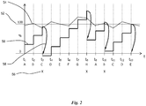
- Figure 2 shows the operation of an algorithm that implements the invention, and proceeds as follows.
- a register increments by a value representing the instantaneous displacement demand of the pump 1, the displacement demand being related to the required torque, pressure or flow in the usual manner.
- the register value is shown as trace 50.
- the controller 12 will activate the valves 14,20 of the corresponding working chamber to pump (or motor) a quantity of fluid.
- the volume of fluid pumped (or motored) is subtracted from the register and the accumulation begins at a lower level at the next timestep. In this way any required flow can be produced from a sequence of working chamber activations.
- the method of this invention provides for a varying secondary parameter to modify the basic threshold 52 to produce an adjusted threshold shown as trace 54, and representing the suitability for use of a working chamber relative to other working chambers.
- the machine according to this invention and example would activate working chamber C at t3 (indicated by mark 56), a particularly suitable time, compared to the previously known machines which would activate working chamber D at time t4, a less suitable time.
- the register is then decremented 58 to a new level.
- the neutrality of time t5 is reflected in that the basic and adjusted thresholds are very similar there.
- the previously known machines would have activated working chamber G due to the register value 50 exceeding the basic threshold 52, but this is a particularly unsuitable working chamber and so the secondary parameter raises the adjusted threshold.
- the working chamber H is instead activated at the delayed time t8.
- the invention can favour or tend to avoid certain working chambers, based on any suitable secondary parameter that indicates their suitability for use, so as to vary the timing of displacement while maintaining the same average throughput of fluid.
- the algorithm may use a different adjusted threshold for each of those working chambers for which a decision is being made, at each timestep, for example to favour one over another.
- the invention can be used to evenly distribute wear or fatigue amongst the working chambers A to H of the pump/motor 1.
- the adjusted threshold could be calculated from an estimate by the controller of the historical wear incurred on the working chamber.
- the historical wear prediction might be simply the historical number of times working chamber has been used previously.
- the algorithm may predict wear by estimating or measuring the amount of wear incurred under the specific operating conditions at the time of the working chamber use, for example weighting more strongly or only accounting for cylinder use at high or low shaft speeds, high or low pressures, high or low temperatures or any other factor or combination of factors related to wear.
- the algorithm could separately account for wear in different components associated with one working chamber, for example the valves, piston or cylinder, using different prediction measures for each.
- the adjusted threshold can be adjusted for a group of working chambers together, due to historical wear.
- the controller may account for wear of the eccentrics, and change the adjusted threshold of all working chambers associated with each eccentric.
- the controller may account for wear of each lobe, and change the adjusted threshold of each working chamber temporarily associated therewith.
- the basic threshold is adjusted to reflect past events, it is possible and advantageous in some situations for the adjusted threshold to represent or model the future situation under the scenario that a certain working chamber is in fact activated or not activated.
- FIG. 3 (a) shows a cam ring 70 for the pump of a hydraulic wind turbine transmission comprising a high torque roller-piston pump and a fast-rotating hydraulic motor.
- the rollers (not shown) roll on the cam ring 70 and are connected to pistons (also not shown) which in turn cycle slidingly inside cylinders to together form working chambers analogous to those in the fluid working machine of Figure 1 .
- the controller controls the pressurisation of the working chambers in the manner previously described (i.e. through the activation of low and high pressure valves with reference to a shaft position sensor), and therefore controls the application of forces 74 by the rollers acting on the cam.
- a bearing 76 is required to hold the cam in place against the net force 78.
- Machines controlled according to the methods of the prior art may easily produce configurations like that shown in Figure 3 a) , in which many working chambers on one side of the cam have been activated but few on the opposite side. This creates a large net force 78, which may unnecessarily wear, distort or even destroy the bearing 76.
- Figure 3 (b) shows the behaviour of a machine having the benefit of the present invention, in which a secondary parameter which predicts the magnitude of the net force on the bearing should a working chamber in question be activated adjusts the basic threshold.
- a pump according to the invention at the moment of deciding which working chambers to activate, calculates, for each possible working chamber or combination thereof that might be activated to fulfil the current demand, the peak magnitude of the net force that would result over the next working chamber volume cycle, and thus chooses to activate that working chamber or those chambers in combination which produces the smallest net force, or the first working chamber found that produces a net force that falls under a certain threshold.
- the net force might be calculated from the working chamber bore size and the high pressure manifold pressure, as well as the geometric position of each working chamber.
- the mean or some other measure could be used.
- a longer or shorter horizon could be used. The method of the invention might therefore cause the fluid working machine to activate the working chambers shown in Figure 3 (b) , to produce a smaller net force 80 on the bearing 76 than in Figure 3 (a) .
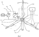
- FIG 4 shows a Wind Turbine Generator (WTG, 100, acting as the power absorbing structure) comprising a nacelle 102 rotatably mounted to a tower 104 and having mounted thereon a hub 106 supporting three blades 108.
- the hub is connected via shaft 110 (shown schematically) to a hydraulic wind turbine transmission comprising a high torque roller-piston ring cam pump 112 and a fast-rotating motor 114, fluidically connected to each other by high pressure line 116 and low pressure line 118.
- the pump and motor are preferably of the type described with reference to Figure 1 .
- the terms pump and motor indicate their most common operation in the WTG and do not necessarily indicate a restriction to operate only in those modes.
- the high 116 and low pressure 118 lines connect to the high 24 and low 17 pressure ports respectively.
- the motor 114 is coupled to a synchronous or other electric generator or motor 120, for example to provide power into an electricity network or to receive power therefrom.
- a controller 12 controls the valves of at least the pump, using input from shaft speed sensor 10 and from a plurality of sensors 122.
- the sensors are accelerometers, strain gauges and relative position sensors, and are used to inform the controller of the current structural condition of the WTG, for example undesirable vibrations in the tower or blades, or resonance conditions.
- the WTG may benefit from the invention by using the algorithm described above with reference to Figure 2 .
- the controller acting as the computer model of the sixth aspect predicts the future motion (structural response) of the WTG by convolving the time response of a proposed working chamber with the known characteristic response of the WTG pump, hydraulic system, tower and blades.
- Such a prediction also uses the current motion (structural condition) from sensors 122.
- Certain parameters of the motion for example whether measurements are exceeded or the relative scale of a plurality of measurements, are used to calculate a secondary parameter to produce the adjusted threshold for each potential working chamber, from the basic threshold, and thence to select the volume displaced by a working chamber based on its suitability compared to other working chambers.
- the WTG compared to WTGs driving pumps controlled according to the prior art, has reduced structural vibration, allowing it to last longer, survive greater hardship, or be built lighter and more cost effectively than previously.
- the motion of two parts of the WTG may be restored to a desirable balanced condition by virtue of the invention.
- Figure 5 shows a portion of a roller piston fluid working machine 112 showing the cam ring 70 comprised of two or more segments 130,132, a wave-shaped surface 134 of which drives a plurality of rollers 136 to cyclically drive a piston 6 in a cylinder 4.
- the controller 12 controls active low pressure valves 14, and optionally controls high pressure valves 20, through control lines 18,26, to fluidically connect or isolate the working chamber from low 16 and high 22 pressure manifolds respectively.
- the controller has a shaft position sensor 10 to measure the shaft position as it rotates in direction 138, and is therefore aware of segment boundaries 140.
- the segment boundaries are typically arranged so that the working chambers are not pressurised when the rollers roll over them in a preferred mode of operation or direction, i.e. the rollers are always unloaded when they cross the segment boundaries.
- the rollers cross the segment boundaries on the expansion stroke of the associated working chamber.
- the fluid working machine may be required to operate at least some of the time as a motor, for example for maintenance purposes, or as a pump in the reverse direction.
- machines of the prior art would activate working chambers so that the rollers cross the segment boundary under load, causing damage and wear.
- a machine employing the method of the invention will use a secondary parameter, derived from the shaft position sensor and predicting whether an activated working chamber would cause a loaded roller to cross a segment boundary, to select which working chambers to activate, and so avoid damage and wear while maintaining the desired output over time.
Landscapes
- Engineering & Computer Science (AREA)
- General Engineering & Computer Science (AREA)
- Mechanical Engineering (AREA)
- Chemical & Material Sciences (AREA)
- Combustion & Propulsion (AREA)
- Sustainable Development (AREA)
- Sustainable Energy (AREA)
- Life Sciences & Earth Sciences (AREA)
- Power Engineering (AREA)
- Computer Hardware Design (AREA)
- Wind Motors (AREA)
- Reciprocating Pumps (AREA)
- Hydraulic Motors (AREA)
- Control Of Positive-Displacement Pumps (AREA)
- Fluid-Pressure Circuits (AREA)
Applications Claiming Priority (2)
| Application Number | Priority Date | Filing Date | Title |
|---|---|---|---|
| GB1003000.5A GB2477997B (en) | 2010-02-23 | 2010-02-23 | Fluid working machine and method for operating fluid working machine |
| PCT/GB2011/050354 WO2011104543A2 (en) | 2010-02-23 | 2011-02-23 | Fluid working machine and method of operating fluid working machine |
Publications (2)
| Publication Number | Publication Date |
|---|---|
| EP2387666A2 EP2387666A2 (en) | 2011-11-23 |
| EP2387666B1 true EP2387666B1 (en) | 2021-10-06 |
Family
ID=42114205
Family Applications (1)
| Application Number | Title | Priority Date | Filing Date |
|---|---|---|---|
| EP11712288.7A Not-in-force EP2387666B1 (en) | 2010-02-23 | 2011-02-23 | Fluid working machine and method of operating fluid working machine |
Country Status (8)
| Country | Link |
|---|---|
| US (1) | US9739266B2 (OSRAM) |
| EP (1) | EP2387666B1 (OSRAM) |
| JP (3) | JP2012523515A (OSRAM) |
| KR (1) | KR101440182B1 (OSRAM) |
| CN (1) | CN103038506B (OSRAM) |
| AU (1) | AU2011211432A1 (OSRAM) |
| GB (1) | GB2477997B (OSRAM) |
| WO (1) | WO2011104543A2 (OSRAM) |
Families Citing this family (27)
| Publication number | Priority date | Publication date | Assignee | Title |
|---|---|---|---|---|
| WO2012022924A1 (en) | 2010-08-17 | 2012-02-23 | Artemis Intelligent Power Limited | Fluid-working machine with multi-lobe ring cam |
| GB2484890A (en) | 2010-08-17 | 2012-05-02 | Artemis Intelligent Power Ltd | Ring cam ensuring smooth follower handover between segments |
| US8316970B1 (en) * | 2011-02-07 | 2012-11-27 | The United States Of America As Represented By The Secretary Of The Navy | Hydraulic-based spherical robot |
| WO2013080399A2 (en) * | 2011-11-30 | 2013-06-06 | Mitsubishi Heavy Industries, Ltd. | Power generating apparatus of renewable energy and method of attaching a hydraulic pump thereof |
| JP5693480B2 (ja) * | 2012-01-31 | 2015-04-01 | 三菱重工業株式会社 | ピストン制御装置、風力発電装置、及びピストン制御方法 |
| WO2014054072A1 (en) | 2012-10-04 | 2014-04-10 | Mitsubishi Heavy Industries, Ltd. | Power generating apparatus of a renewable energy type having hydraulic pump also operable in motoring mode |
| WO2014118906A1 (ja) * | 2013-01-30 | 2014-08-07 | 三菱重工業株式会社 | 油圧システム、風力発電装置及びそれらの制御方法 |
| EP2851586B1 (en) * | 2013-09-18 | 2016-11-30 | MITSUBISHI HEAVY INDUSTRIES, Ltd. | Hydraulic transmission |
| JP6262994B2 (ja) * | 2013-09-18 | 2018-01-17 | 三菱重工業株式会社 | 油圧トランスミッション及びこれを含む機械、並びに、油圧トランスミッションの運転方法 |
| EP2895742B1 (en) | 2013-09-18 | 2016-07-13 | Artemis Intelligent Power Limited | Hydraulic transmission |
| JP6140071B2 (ja) * | 2013-12-27 | 2017-05-31 | 三菱重工業株式会社 | 油圧トランスミッション及び再生エネルギー型発電装置、並びにそれらの運転方法 |
| JP6165703B2 (ja) * | 2014-12-02 | 2017-07-19 | 三菱重工業株式会社 | 油圧システム及び再生エネルギー型発電装置、並びにその運転方法 |
| US11655816B2 (en) | 2015-05-08 | 2023-05-23 | Danfoss Power Solutions Gmbh & Co. Ohg | Fluid working systems |
| JP6421099B2 (ja) * | 2015-08-27 | 2018-11-07 | 三菱重工業株式会社 | 油圧機械及びその運転方法、並びに再生エネルギー型発電装置 |
| GB2546485A (en) * | 2016-01-15 | 2017-07-26 | Artemis Intelligent Power Ltd | Hydraulic apparatus comprising synthetically commutated machine, and operating method |
| JP6444905B2 (ja) * | 2016-01-26 | 2018-12-26 | 三菱重工業株式会社 | 油圧機械、リングカム及び再生可能エネルギー型発電装置 |
| NO342168B1 (en) * | 2016-11-04 | 2018-04-09 | Diinef As | A method for controlling torque equilibrium of a hydraulic motor |
| JP7269650B2 (ja) * | 2017-05-23 | 2023-05-09 | ニュー リーフ マネジメント リミテッド | 係留された翼を使用して風力エネルギーを利用する方法およびシステム |
| DK3454469T3 (da) * | 2017-09-12 | 2022-03-21 | Siemens Gamesa Renewable Energy As | Drejningsmoment-ripple-reduktion for en generator og vindmølle indbefattende samme |
| EP3514378B1 (en) * | 2018-01-19 | 2022-03-16 | Artemis Intelligent Power Limited | Displacement of an object with hydraulic actuators |
| DE102018103252B4 (de) * | 2018-02-14 | 2022-01-20 | Danfoss Power Solutions Gmbh & Co. Ohg | Verfahren und Vorrichtung zur Entlüftung der Ansaugseite einer künstlich kommutierten Hydraulikpumpe |
| EP3894702B1 (en) * | 2018-12-11 | 2024-06-12 | Kline, Robert D. | Variable output, hydraulic drive system |
| EP3674546B1 (en) * | 2018-12-28 | 2022-07-13 | Artemis Intelligent Power Limited | Valve timing in electronically commutated hydraulic machine |
| JP2020197304A (ja) * | 2019-06-04 | 2020-12-10 | アルテミス インテリジェント パワー リミティドArtemis Intelligent Power Limited | 油圧機械およびシステム |
| DE102020211030A1 (de) * | 2020-09-02 | 2022-03-03 | Robert Bosch Gesellschaft mit beschränkter Haftung | Verfahren zum Betreiben einer Pumpe und Fluid-Versorgungssystem mit einer solchen Pumpe |
| CN112761918A (zh) * | 2020-12-31 | 2021-05-07 | 大连传术节能泵有限公司研发中心 | 大流量柱塞水泵 |
| US12454945B2 (en) | 2022-05-03 | 2025-10-28 | Regents Of The University Of Minnesota | Partial stroke fluidic pump-motor with high mechanical efficiency |
Family Cites Families (97)
| Publication number | Priority date | Publication date | Assignee | Title |
|---|---|---|---|---|
| US3928968A (en) | 1974-10-04 | 1975-12-30 | Sperry Rand Corp | Power transmission |
| JPS52144568A (en) | 1976-05-28 | 1977-12-01 | Isamu Takasu | Reduction gear |
| CH641907A5 (en) | 1979-03-27 | 1984-03-15 | Burckhardt Ag Maschf | Device for monitoring the operational characteristic of the valves of a piston compressor |
| US4301827A (en) | 1980-02-25 | 1981-11-24 | Koomey, Inc. | Accumulator with preclosing preventer |
| US4496846A (en) | 1982-06-04 | 1985-01-29 | Parkins William E | Power generation from wind |
| US4496847A (en) | 1982-06-04 | 1985-01-29 | Parkins William E | Power generation from wind |
| DE3244738A1 (de) | 1982-12-03 | 1984-06-07 | Uraca Pumpenfabrik GmbH & Co KG, 7432 Urach | Vorrichtung zur ueberwachung von ventilen einer intermittierend arbeitenden maschine |
| JPS6069344A (ja) | 1983-08-31 | 1985-04-20 | Mazda Motor Corp | 気筒数制御エンジンのバランサ装置 |
| JPS6133932U (ja) | 1984-07-31 | 1986-03-01 | 川崎重工業株式会社 | ガスエンジンの異常検出装置 |
| JPS6220681A (ja) | 1985-07-19 | 1987-01-29 | Toshiba Corp | 流体加圧設備の故障ポンプチエツク方法 |
| US4965513A (en) | 1986-09-30 | 1990-10-23 | Martin Marietta Energy Systems, Inc. | Motor current signature analysis method for diagnosing motor operated devices |
| GB8822901D0 (en) * | 1988-09-29 | 1988-11-02 | Mactaggart Scot Holdings Ltd | Apparatus & method for controlling actuation of multi-piston pump &c |
| EP0494236B1 (en) | 1988-09-29 | 1995-12-13 | Artemis Intelligent Power Ltd. | Improved fluid-working machine |
| DE3925297A1 (de) * | 1989-07-31 | 1991-02-07 | Linde Ag | Steuereinrichtung fuer eine verstellbare hydrostatische maschine |
| EP0471098A1 (en) | 1990-08-13 | 1992-02-19 | Sato, Hiroshi | Hydraulic piston apparatus |
| JP3033214B2 (ja) | 1991-02-27 | 2000-04-17 | 株式会社デンソー | 複数の燃料圧送手段による蓄圧式燃料供給方法及び装置と、複数の流体圧送手段を有する機器における異常判断装置 |
| DE4118580A1 (de) | 1991-06-06 | 1992-12-10 | Bosch Gmbh Robert | System zum erkennen von aussetzern in einem verbrennungsmotor |
| JP2783734B2 (ja) | 1992-09-29 | 1998-08-06 | 株式会社デンソー | 車両用負圧ポンプ並列駆動装置 |
| SE500151C2 (sv) | 1993-03-30 | 1994-04-25 | Ulf Henricson | Hydrauliskt drivsystem för drift av företrädesvis tunga industriella arbetsenheter |
| US5445019A (en) | 1993-04-19 | 1995-08-29 | Ford Motor Company | Internal combustion engine with on-board diagnostic system for detecting impaired fuel injectors |
| US5564391A (en) | 1993-06-16 | 1996-10-15 | Caterpillar Inc. | Electronic control for a hydraulic-actuator unit injector fuel system and method for operating same |
| US5439355A (en) | 1993-11-03 | 1995-08-08 | Abbott Laboratories | Method and apparatus to test for valve leakage in a pump assembly |
| US5456581A (en) | 1994-08-12 | 1995-10-10 | The United States Of America As Represented By The Secretary Of The Navy | Control system for a multi-piston pump with solenoid valves for the production of constant outlet pressure flow |
| JP3535233B2 (ja) | 1994-10-18 | 2004-06-07 | ヤマハマリン株式会社 | 船外機用2サイクルエンジンの運転制御装置 |
| US5492099A (en) | 1995-01-06 | 1996-02-20 | Caterpillar Inc. | Cylinder fault detection using rail pressure signal |
| JP3449041B2 (ja) | 1995-06-02 | 2003-09-22 | 株式会社デンソー | 内燃機関の燃料供給装置 |
| US5711273A (en) | 1995-08-31 | 1998-01-27 | Caterpillar Inc. | Method for controlling the operation of a driver circuit in response to an electrical fault condition |
| ES2174137T3 (es) | 1996-01-19 | 2002-11-01 | Fiat Ricerche | Metodo y unidad de diagnostico de fugas de un sistema de inyeccion de alta presion de un motor de combustion interna. |
| GB2314412B (en) | 1996-06-19 | 2000-07-26 | Richard Czaja | Method of monitoring pump performance |
| DE19625947C1 (de) | 1996-06-28 | 1997-09-18 | Uraca Pumpen | Verfahren zur Störungsfrüherkennung an Pumpen sowie entsprechende Vorrichtung |
| DE19780822B4 (de) | 1996-08-12 | 2006-02-23 | Hitachi Construction Machinery Co., Ltd. | Hydraulikvorrichtung zur Bestimmung von Fehlern von Hydropumpen in einem Arbeitsfahrzeug |
| JP3857361B2 (ja) | 1996-08-12 | 2006-12-13 | 日立建機株式会社 | 作業機械の油圧ポンプ故障診断装置 |
| US5737994A (en) | 1996-11-27 | 1998-04-14 | Escobosa; Alfonso S. | Digital variable actuation system |
| DE19651671C2 (de) | 1996-12-12 | 2001-10-04 | Daimler Chrysler Ag | Steuerung einer Einspritzanlage für eine mehrzylindrige Brennkraftmaschine |
| US6092370A (en) | 1997-09-16 | 2000-07-25 | Flow International Corporation | Apparatus and method for diagnosing the status of specific components in high-pressure fluid pumps |
| JPH11117875A (ja) | 1997-10-14 | 1999-04-27 | Tokyo Gas Co Ltd | 音響によるコンプレッサの監視装置 |
| JP3413092B2 (ja) | 1998-01-08 | 2003-06-03 | 日立建機株式会社 | 油圧作業機のポンプ故障警告装置 |
| GB2349482B (en) | 1998-12-22 | 2003-07-09 | Caterpillar Inc | Tool recognition and control system for a work machine |
| KR100273463B1 (ko) | 1998-12-31 | 2000-12-15 | 구자홍 | 부스터 펌프 시스템의 인버터 교대운전 제어회로및 방법 |
| DE19908352A1 (de) | 1999-02-26 | 2000-08-31 | Bosch Gmbh Robert | Kraftstoffeinspritzverfahren für eine Brennkraftmaschine |
| DE19924377B4 (de) | 1999-05-27 | 2004-12-02 | Siemens Ag | Diagnosesystem für ein von einem Stellungsregler über einen Antrieb betätigbares Ventil |
| US6293251B1 (en) | 1999-07-20 | 2001-09-25 | Cummins Engine, Inc. | Apparatus and method for diagnosing erratic pressure sensor operation in a fuel system of an internal combustion engine |
| DE19947570B4 (de) | 1999-10-02 | 2016-07-14 | MARIDIS Maritime Diagnose & Service GmbH | Verfahren zum Erkennen von Undichtigkeiten an Kolbenmaschinen während des laufenden Betriebes |
| US6478547B1 (en) * | 1999-10-18 | 2002-11-12 | Integrated Designs L.P. | Method and apparatus for dispensing fluids |
| US6917845B2 (en) * | 2000-03-10 | 2005-07-12 | Smiths Detection-Pasadena, Inc. | Method for monitoring environmental condition using a mathematical model |
| US6829542B1 (en) | 2000-05-31 | 2004-12-07 | Warren Rupp, Inc. | Pump and method for facilitating maintenance and adjusting operation of said pump |
| JP2002041143A (ja) | 2000-07-31 | 2002-02-08 | Chiyoda Corp | 動作部の異常診断方法及び圧縮機のバルブ異常診断方法 |
| JP2002242849A (ja) * | 2001-02-15 | 2002-08-28 | Hitachi Constr Mach Co Ltd | 油圧駆動装置のポンプ故障診断装置及びその表示装置 |
| DE10124564A1 (de) | 2001-05-14 | 2002-11-28 | Joma Hydromechanic Gmbh | Verfahren zum Verstellen einer volumenstromvariablen Verdrängerpumpe in einem Brennkraftmotor |
| US6651545B2 (en) | 2001-12-13 | 2003-11-25 | Caterpillar Inc | Fluid translating device |
| US6681571B2 (en) * | 2001-12-13 | 2004-01-27 | Caterpillar Inc | Digital controlled fluid translating device |
| JP2003314460A (ja) | 2002-04-23 | 2003-11-06 | Daikin Ind Ltd | 圧縮機の連続容量制御装置 |
| US7241615B2 (en) * | 2002-08-30 | 2007-07-10 | St Lawrence Thomas W | Wet combustion engine |
| GB0221165D0 (en) * | 2002-09-12 | 2002-10-23 | Artemis Intelligent Power Ltd | Fluid-working machine and operating method |
| US7993108B2 (en) | 2002-10-09 | 2011-08-09 | Abbott Diabetes Care Inc. | Variable volume, shape memory actuated insulin dispensing pump |
| US6970793B2 (en) | 2003-02-10 | 2005-11-29 | Flow International Corporation | Apparatus and method for detecting malfunctions in high-pressure fluid pumps |
| JP3948432B2 (ja) | 2003-05-16 | 2007-07-25 | 株式会社豊田自動織機 | 容量可変型圧縮機の制御装置 |
| DE10322220C5 (de) | 2003-05-16 | 2010-10-14 | Lewa Gmbh | Störungsfrüherkennung an Pumpenventilen |
| DE10334817A1 (de) | 2003-07-30 | 2005-03-10 | Bosch Rexroth Ag | Vorrichtung und Verfahren zur Fehlererkennung an Pumpen |
| US8577473B2 (en) | 2004-03-08 | 2013-11-05 | Med-El Elektromedizinische Geraete Gmbh | Cochlear implant stimulation with low frequency channel privilege |
| GB0407297D0 (en) * | 2004-03-31 | 2004-05-05 | Caldwell N J | Fluid working machine with displacement control |
| WO2005106203A1 (es) | 2004-04-29 | 2005-11-10 | Francisco Javier Ruiz Martinez | Motor rotativo equilibrado |
| GB0411447D0 (en) | 2004-05-21 | 2004-06-23 | Navitas Uk Ltd | Valve monitoring system |
| US7303678B2 (en) * | 2005-04-04 | 2007-12-04 | Njun, Llc | Method for treating wastewater |
| JP4410640B2 (ja) | 2004-09-06 | 2010-02-03 | 株式会社小松製作所 | 作業車両のエンジンの負荷制御装置 |
| DE102004062029A1 (de) | 2004-12-23 | 2006-07-13 | Robert Bosch Gmbh | Überwachung einer Mehrkolbenpumpe |
| US7477960B2 (en) * | 2005-02-16 | 2009-01-13 | Tokyo Electron Limited | Fault detection and classification (FDC) using a run-to-run controller |
| DE102005008180A1 (de) | 2005-02-23 | 2006-08-31 | Robert Bosch Gmbh | Verfahren und Vorrichtung zur Überwachung einer Einspritzvorrichtung einer Brennkraftmaschine |
| DE102005017240A1 (de) | 2005-04-14 | 2006-10-19 | Alldos Eichler Gmbh | Verfahren und Vorrichtung zur Überwachung eines mittels einer Pumpe geförderten Fluidstromes |
| GB0507662D0 (en) | 2005-04-15 | 2005-05-25 | Artemis Intelligent Power Ltd | Fluid-working machines |
| US7534082B2 (en) | 2005-07-27 | 2009-05-19 | The Boeing Company | Cargo container handling system and associated method |
| CN2849495Y (zh) | 2005-09-21 | 2006-12-20 | 浙江大学 | 往复式多孔介质燃烧高温空气发生系统 |
| JP2007092582A (ja) | 2005-09-28 | 2007-04-12 | Sanyo Epson Imaging Devices Corp | 流体制御装置及び流体制御方法 |
| JP4506662B2 (ja) | 2005-12-05 | 2010-07-21 | 株式会社デンソー | 燃料噴射制御装置 |
| DE102005059566B4 (de) | 2005-12-13 | 2022-04-21 | Brueninghaus Hydromatik Gmbh | Vorrichtung und Verfahren zur zustandsabhängigen Wartung von hydrostatischen Verdrängereinheiten |
| DE102006001585A1 (de) | 2006-01-12 | 2007-07-19 | Rehau Ag + Co. | Verfahren zur Verschleißüberwachung von Pumpen und Pumpe zur Durchführung des Verfahrens |
| GB0602111D0 (en) * | 2006-02-02 | 2006-03-15 | Artemis Intelligent Power Ltd | Operating method for a hydraulic machine |
| WO2007099057A2 (de) | 2006-02-28 | 2007-09-07 | Auma Riester Gmbh+Co. Kg | Verfahren und vorrichtung zur überwachung, diagnose oder justage eines stellglieds zur betätigung einer armatur |
| DE102006029992A1 (de) | 2006-06-29 | 2008-01-03 | Robert Bosch Gmbh | Verfahren zur Diagnose einer elektrischen Schaltung |
| GB0614534D0 (en) | 2006-07-21 | 2006-08-30 | Artemis Intelligent Power Ltd | Fluid power distribution and control system |
| GB0614930D0 (en) | 2006-07-27 | 2006-09-06 | Arternis Intelligent Power Ltd | Hydrostatic regenerative drive system |
| GB0614940D0 (en) | 2006-07-27 | 2006-09-06 | Arternis Intelligent Power Ltd | Vehicle traction and stability control system employing control of fluid quanta |
| JP4187020B2 (ja) * | 2006-08-08 | 2008-11-26 | ダイキン工業株式会社 | 空気調和装置およびその洗浄方法 |
| DE102006041087A1 (de) | 2006-09-01 | 2008-03-06 | Robert Bosch Gmbh | Steuereinrichtung für eine hydraulische Kolbenmaschine mit veränderbarem Volumenstrom |
| DE102007029670A1 (de) | 2006-10-20 | 2008-04-24 | Robert Bosch Gmbh | Hydraulische Arbeitsmaschine |
| DE102006055747B4 (de) | 2006-11-25 | 2021-08-26 | Abb Ag | Verfahren und Anordnung zur Diagnose eines Stellorgans |
| JP5084295B2 (ja) | 2007-02-09 | 2012-11-28 | 日立建機株式会社 | 油圧建設機械のポンプトルク制御装置 |
| US8506262B2 (en) | 2007-05-11 | 2013-08-13 | Schlumberger Technology Corporation | Methods of use for a positive displacement pump having an externally assisted valve |
| RU2344320C1 (ru) * | 2007-05-14 | 2009-01-20 | Николай Филиппович Рысев | Способ управления гидроприводным насосным агрегатом нефтедобывающих скважин и устройство для его осуществления |
| DE602008001854D1 (de) * | 2007-11-01 | 2010-09-02 | Sauer Danfoss Aps | Verfahren zur Steuerung einer zyklisch kommutierten hydraulischen Pumpe |
| EP2055945B8 (en) * | 2007-11-01 | 2017-12-06 | Danfoss Power Solutions Aps | Method of operating a fluid working machine |
| EP2055943B1 (en) | 2007-11-01 | 2017-07-26 | Danfoss Power Solutions Aps | Method of operating a fluid working machine |
| EP2055946A1 (en) | 2007-11-01 | 2009-05-06 | Sauer-Danfoss ApS | Operating mehtod for fluid working machine |
| GB2459520B (en) * | 2008-06-20 | 2010-06-16 | Artemis Intelligent Power Ltd | Fluid working machines and methods |
| GB0811385D0 (en) | 2008-06-20 | 2008-07-30 | Artemis Intelligent Power Ltd | Fluid working machines and method |
| US20140026548A1 (en) | 2011-04-15 | 2014-01-30 | Volvo Construction Equipment Ab | Method and a device for reducing vibrations in a working machine |
| JP6108976B2 (ja) | 2013-06-18 | 2017-04-05 | 極東開発工業株式会社 | 長尺物運搬兼コンテナ運搬用荷役車両 |
-
2010
- 2010-02-23 GB GB1003000.5A patent/GB2477997B/en not_active Expired - Fee Related
-
2011
- 2011-02-23 WO PCT/GB2011/050354 patent/WO2011104543A2/en not_active Ceased
- 2011-02-23 KR KR1020117024234A patent/KR101440182B1/ko not_active Expired - Fee Related
- 2011-02-23 AU AU2011211432A patent/AU2011211432A1/en not_active Abandoned
- 2011-02-23 JP JP2012501391A patent/JP2012523515A/ja active Pending
- 2011-02-23 EP EP11712288.7A patent/EP2387666B1/en not_active Not-in-force
- 2011-02-23 US US13/320,127 patent/US9739266B2/en not_active Expired - Fee Related
- 2011-02-23 CN CN201180001501.6A patent/CN103038506B/zh not_active Expired - Fee Related
-
2016
- 2016-08-01 JP JP2016151084A patent/JP2016186312A/ja active Pending
-
2017
- 2017-02-22 JP JP2017031008A patent/JP6408048B2/ja not_active Expired - Fee Related
Non-Patent Citations (1)
| Title |
|---|
| None * |
Also Published As
| Publication number | Publication date |
|---|---|
| WO2011104543A2 (en) | 2011-09-01 |
| KR20120018289A (ko) | 2012-03-02 |
| CN103038506A (zh) | 2013-04-10 |
| JP2017122458A (ja) | 2017-07-13 |
| WO2011104543A3 (en) | 2013-08-15 |
| GB2477997B (en) | 2015-01-14 |
| GB2477997A (en) | 2011-08-24 |
| CN103038506B (zh) | 2016-06-15 |
| KR101440182B1 (ko) | 2014-09-12 |
| JP2012523515A (ja) | 2012-10-04 |
| US9739266B2 (en) | 2017-08-22 |
| JP2016186312A (ja) | 2016-10-27 |
| GB201003000D0 (en) | 2010-04-07 |
| AU2011211432A1 (en) | 2011-09-08 |
| JP6408048B2 (ja) | 2018-10-17 |
| US20120059523A1 (en) | 2012-03-08 |
| EP2387666A2 (en) | 2011-11-23 |
Similar Documents
| Publication | Publication Date | Title |
|---|---|---|
| US9739266B2 (en) | Fluid-working machine and method of operating a fluid-working machine | |
| EP2440776B1 (en) | Fluid-working machine with multi-lobe ring cam | |
| EP2649348B1 (en) | Hydraulic transmission comprising variable displacement pump or motor operable with discontinuous range of displacements | |
| CN108474362B (zh) | 包括合成换向机器的液压设备,以及操作方法 | |
| JP7253387B2 (ja) | 油圧アクチュエータを有する物体の配置 | |
| JP5398746B2 (ja) | 風力発電装置及び潮流発電装置並びにその運転制御方法 | |
| EP2054621B1 (en) | A digital hydraulic pump/motor torque modulation system and apparatus | |
| KR101613323B1 (ko) | 유체 작동 기계의 작동 방법 | |
| JP5463409B2 (ja) | 流体作動機械及び流体作動機械を操作する方法 | |
| US20100207390A1 (en) | Converter and method for converting mechanical energy into electrical energy | |
| JP2012523515A5 (OSRAM) | ||
| CN112112776A (zh) | 液压机和系统 | |
| JP6242765B2 (ja) | 油圧トランスミッション | |
| JP5818967B2 (ja) | モータリングモードでの運転が可能な油圧ポンプを備える再生可能エネルギー型発電装置 | |
| US20120045327A1 (en) | Fluid-Working Machine with Multi-Lobe Ring Cam | |
| JP2015059658A (ja) | 油圧トランスミッション及び油圧トランスミッションの制御方法 | |
| Heikkilä et al. | Comparison of proportional control and displacement control using digital hydraulic power management system |
Legal Events
| Date | Code | Title | Description |
|---|---|---|---|
| PUAI | Public reference made under article 153(3) epc to a published international application that has entered the european phase |
Free format text: ORIGINAL CODE: 0009012 |
|
| 17P | Request for examination filed |
Effective date: 20110729 |
|
| AK | Designated contracting states |
Kind code of ref document: A2 Designated state(s): AL AT BE BG CH CY CZ DE DK EE ES FI FR GB GR HR HU IE IS IT LI LT LU LV MC MK MT NL NO PL PT RO RS SE SI SK SM TR |
|
| RIN1 | Information on inventor provided before grant (corrected) |
Inventor name: JOLY, PIERRE, ROBERT Inventor name: CALDWELL, NIALL, JAMES Inventor name: SALTER, STEPHEN, HUGH Inventor name: RAMPEN, WILLIAM, HUGH, SALVIN Inventor name: LAIRD, STEPHEN, MICHAEL Inventor name: FIELDING, MICHAEL, RICHARD |
|
| DAX | Request for extension of the european patent (deleted) | ||
| R17D | Deferred search report published (corrected) |
Effective date: 20130815 |
|
| STAA | Information on the status of an ep patent application or granted ep patent |
Free format text: STATUS: EXAMINATION IS IN PROGRESS |
|
| 17Q | First examination report despatched |
Effective date: 20180920 |
|
| REG | Reference to a national code |
Ref country code: DE Ref legal event code: R079 Ref document number: 602011071883 Country of ref document: DE Free format text: PREVIOUS MAIN CLASS: F04B0001060000 Ipc: F03D0009250000 |
|
| GRAP | Despatch of communication of intention to grant a patent |
Free format text: ORIGINAL CODE: EPIDOSNIGR1 |
|
| STAA | Information on the status of an ep patent application or granted ep patent |
Free format text: STATUS: GRANT OF PATENT IS INTENDED |
|
| RIC1 | Information provided on ipc code assigned before grant |
Ipc: F03D 9/25 20160101AFI20200930BHEP |
|
| INTG | Intention to grant announced |
Effective date: 20201022 |
|
| GRAJ | Information related to disapproval of communication of intention to grant by the applicant or resumption of examination proceedings by the epo deleted |
Free format text: ORIGINAL CODE: EPIDOSDIGR1 |
|
| STAA | Information on the status of an ep patent application or granted ep patent |
Free format text: STATUS: EXAMINATION IS IN PROGRESS |
|
| INTC | Intention to grant announced (deleted) | ||
| RIN1 | Information on inventor provided before grant (corrected) |
Inventor name: LAIRD, STEPHEN, MICHAEL Inventor name: FIELDING, MICHAEL, RICHARD Inventor name: RAMPEN, WILLIAM, HUGH, SALVIN Inventor name: CALDWELL, NIALL, JAMES Inventor name: JOLY, PIERRE, ROBERT Inventor name: SALTER, STEPHEN, HUGH |
|
| GRAP | Despatch of communication of intention to grant a patent |
Free format text: ORIGINAL CODE: EPIDOSNIGR1 |
|
| STAA | Information on the status of an ep patent application or granted ep patent |
Free format text: STATUS: GRANT OF PATENT IS INTENDED |
|
| INTG | Intention to grant announced |
Effective date: 20210506 |
|
| GRAS | Grant fee paid |
Free format text: ORIGINAL CODE: EPIDOSNIGR3 |
|
| GRAA | (expected) grant |
Free format text: ORIGINAL CODE: 0009210 |
|
| STAA | Information on the status of an ep patent application or granted ep patent |
Free format text: STATUS: THE PATENT HAS BEEN GRANTED |
|
| RBV | Designated contracting states (corrected) |
Designated state(s): AL AT BE BG CH CY CZ DE DK EE ES FI FR GR HR HU IE IS IT LI LT LU LV MC MK MT NL NO PL PT RO RS SE SI SK SM TR |
|
| AK | Designated contracting states |
Kind code of ref document: B1 Designated state(s): AL AT BE BG CH CY CZ DE DK EE ES FI FR GR HR HU IE IS IT LI LT LU LV MC MK MT NL NO PL PT RO RS SE SI SK SM TR |
|
| REG | Reference to a national code |
Ref country code: CH Ref legal event code: EP Ref country code: AT Ref legal event code: REF Ref document number: 1436451 Country of ref document: AT Kind code of ref document: T Effective date: 20211015 |
|
| REG | Reference to a national code |
Ref country code: IE Ref legal event code: FG4D |
|
| REG | Reference to a national code |
Ref country code: DE Ref legal event code: R096 Ref document number: 602011071883 Country of ref document: DE |
|
| REG | Reference to a national code |
Ref country code: NO Ref legal event code: T2 Effective date: 20211006 |
|
| REG | Reference to a national code |
Ref country code: SE Ref legal event code: TRGR |
|
| REG | Reference to a national code |
Ref country code: LT Ref legal event code: MG9D |
|
| REG | Reference to a national code |
Ref country code: NL Ref legal event code: MP Effective date: 20211006 |
|
| REG | Reference to a national code |
Ref country code: AT Ref legal event code: MK05 Ref document number: 1436451 Country of ref document: AT Kind code of ref document: T Effective date: 20211006 |
|
| PG25 | Lapsed in a contracting state [announced via postgrant information from national office to epo] |
Ref country code: RS Free format text: LAPSE BECAUSE OF FAILURE TO SUBMIT A TRANSLATION OF THE DESCRIPTION OR TO PAY THE FEE WITHIN THE PRESCRIBED TIME-LIMIT Effective date: 20211006 Ref country code: LT Free format text: LAPSE BECAUSE OF FAILURE TO SUBMIT A TRANSLATION OF THE DESCRIPTION OR TO PAY THE FEE WITHIN THE PRESCRIBED TIME-LIMIT Effective date: 20211006 Ref country code: FI Free format text: LAPSE BECAUSE OF FAILURE TO SUBMIT A TRANSLATION OF THE DESCRIPTION OR TO PAY THE FEE WITHIN THE PRESCRIBED TIME-LIMIT Effective date: 20211006 Ref country code: BG Free format text: LAPSE BECAUSE OF FAILURE TO SUBMIT A TRANSLATION OF THE DESCRIPTION OR TO PAY THE FEE WITHIN THE PRESCRIBED TIME-LIMIT Effective date: 20220106 Ref country code: AT Free format text: LAPSE BECAUSE OF FAILURE TO SUBMIT A TRANSLATION OF THE DESCRIPTION OR TO PAY THE FEE WITHIN THE PRESCRIBED TIME-LIMIT Effective date: 20211006 |
|
| PG25 | Lapsed in a contracting state [announced via postgrant information from national office to epo] |
Ref country code: IS Free format text: LAPSE BECAUSE OF FAILURE TO SUBMIT A TRANSLATION OF THE DESCRIPTION OR TO PAY THE FEE WITHIN THE PRESCRIBED TIME-LIMIT Effective date: 20220206 Ref country code: PT Free format text: LAPSE BECAUSE OF FAILURE TO SUBMIT A TRANSLATION OF THE DESCRIPTION OR TO PAY THE FEE WITHIN THE PRESCRIBED TIME-LIMIT Effective date: 20220207 Ref country code: PL Free format text: LAPSE BECAUSE OF FAILURE TO SUBMIT A TRANSLATION OF THE DESCRIPTION OR TO PAY THE FEE WITHIN THE PRESCRIBED TIME-LIMIT Effective date: 20211006 Ref country code: NL Free format text: LAPSE BECAUSE OF FAILURE TO SUBMIT A TRANSLATION OF THE DESCRIPTION OR TO PAY THE FEE WITHIN THE PRESCRIBED TIME-LIMIT Effective date: 20211006 Ref country code: LV Free format text: LAPSE BECAUSE OF FAILURE TO SUBMIT A TRANSLATION OF THE DESCRIPTION OR TO PAY THE FEE WITHIN THE PRESCRIBED TIME-LIMIT Effective date: 20211006 Ref country code: HR Free format text: LAPSE BECAUSE OF FAILURE TO SUBMIT A TRANSLATION OF THE DESCRIPTION OR TO PAY THE FEE WITHIN THE PRESCRIBED TIME-LIMIT Effective date: 20211006 Ref country code: GR Free format text: LAPSE BECAUSE OF FAILURE TO SUBMIT A TRANSLATION OF THE DESCRIPTION OR TO PAY THE FEE WITHIN THE PRESCRIBED TIME-LIMIT Effective date: 20220107 Ref country code: ES Free format text: LAPSE BECAUSE OF FAILURE TO SUBMIT A TRANSLATION OF THE DESCRIPTION OR TO PAY THE FEE WITHIN THE PRESCRIBED TIME-LIMIT Effective date: 20211006 |
|
| REG | Reference to a national code |
Ref country code: DE Ref legal event code: R097 Ref document number: 602011071883 Country of ref document: DE |
|
| PG25 | Lapsed in a contracting state [announced via postgrant information from national office to epo] |
Ref country code: SM Free format text: LAPSE BECAUSE OF FAILURE TO SUBMIT A TRANSLATION OF THE DESCRIPTION OR TO PAY THE FEE WITHIN THE PRESCRIBED TIME-LIMIT Effective date: 20211006 Ref country code: SK Free format text: LAPSE BECAUSE OF FAILURE TO SUBMIT A TRANSLATION OF THE DESCRIPTION OR TO PAY THE FEE WITHIN THE PRESCRIBED TIME-LIMIT Effective date: 20211006 Ref country code: RO Free format text: LAPSE BECAUSE OF FAILURE TO SUBMIT A TRANSLATION OF THE DESCRIPTION OR TO PAY THE FEE WITHIN THE PRESCRIBED TIME-LIMIT Effective date: 20211006 Ref country code: EE Free format text: LAPSE BECAUSE OF FAILURE TO SUBMIT A TRANSLATION OF THE DESCRIPTION OR TO PAY THE FEE WITHIN THE PRESCRIBED TIME-LIMIT Effective date: 20211006 Ref country code: DK Free format text: LAPSE BECAUSE OF FAILURE TO SUBMIT A TRANSLATION OF THE DESCRIPTION OR TO PAY THE FEE WITHIN THE PRESCRIBED TIME-LIMIT Effective date: 20211006 Ref country code: CZ Free format text: LAPSE BECAUSE OF FAILURE TO SUBMIT A TRANSLATION OF THE DESCRIPTION OR TO PAY THE FEE WITHIN THE PRESCRIBED TIME-LIMIT Effective date: 20211006 |
|
| PLBE | No opposition filed within time limit |
Free format text: ORIGINAL CODE: 0009261 |
|
| STAA | Information on the status of an ep patent application or granted ep patent |
Free format text: STATUS: NO OPPOSITION FILED WITHIN TIME LIMIT |
|
| 26N | No opposition filed |
Effective date: 20220707 |
|
| PG25 | Lapsed in a contracting state [announced via postgrant information from national office to epo] |
Ref country code: MC Free format text: LAPSE BECAUSE OF FAILURE TO SUBMIT A TRANSLATION OF THE DESCRIPTION OR TO PAY THE FEE WITHIN THE PRESCRIBED TIME-LIMIT Effective date: 20211006 |
|
| REG | Reference to a national code |
Ref country code: CH Ref legal event code: PL |
|
| REG | Reference to a national code |
Ref country code: BE Ref legal event code: MM Effective date: 20220228 |
|
| PG25 | Lapsed in a contracting state [announced via postgrant information from national office to epo] |
Ref country code: LU Free format text: LAPSE BECAUSE OF NON-PAYMENT OF DUE FEES Effective date: 20220223 Ref country code: AL Free format text: LAPSE BECAUSE OF FAILURE TO SUBMIT A TRANSLATION OF THE DESCRIPTION OR TO PAY THE FEE WITHIN THE PRESCRIBED TIME-LIMIT Effective date: 20211006 |
|
| PG25 | Lapsed in a contracting state [announced via postgrant information from national office to epo] |
Ref country code: SI Free format text: LAPSE BECAUSE OF FAILURE TO SUBMIT A TRANSLATION OF THE DESCRIPTION OR TO PAY THE FEE WITHIN THE PRESCRIBED TIME-LIMIT Effective date: 20211006 |
|
| PG25 | Lapsed in a contracting state [announced via postgrant information from national office to epo] |
Ref country code: LI Free format text: LAPSE BECAUSE OF NON-PAYMENT OF DUE FEES Effective date: 20220228 Ref country code: IE Free format text: LAPSE BECAUSE OF NON-PAYMENT OF DUE FEES Effective date: 20220223 Ref country code: CH Free format text: LAPSE BECAUSE OF NON-PAYMENT OF DUE FEES Effective date: 20220228 |
|
| PG25 | Lapsed in a contracting state [announced via postgrant information from national office to epo] |
Ref country code: BE Free format text: LAPSE BECAUSE OF NON-PAYMENT OF DUE FEES Effective date: 20220228 |
|
| PGFP | Annual fee paid to national office [announced via postgrant information from national office to epo] |
Ref country code: NO Payment date: 20230208 Year of fee payment: 13 |
|
| PG25 | Lapsed in a contracting state [announced via postgrant information from national office to epo] |
Ref country code: IT Free format text: LAPSE BECAUSE OF FAILURE TO SUBMIT A TRANSLATION OF THE DESCRIPTION OR TO PAY THE FEE WITHIN THE PRESCRIBED TIME-LIMIT Effective date: 20211006 |
|
| P01 | Opt-out of the competence of the unified patent court (upc) registered |
Effective date: 20230621 |
|
| PG25 | Lapsed in a contracting state [announced via postgrant information from national office to epo] |
Ref country code: HU Free format text: LAPSE BECAUSE OF FAILURE TO SUBMIT A TRANSLATION OF THE DESCRIPTION OR TO PAY THE FEE WITHIN THE PRESCRIBED TIME-LIMIT; INVALID AB INITIO Effective date: 20110223 |
|
| PG25 | Lapsed in a contracting state [announced via postgrant information from national office to epo] |
Ref country code: MK Free format text: LAPSE BECAUSE OF FAILURE TO SUBMIT A TRANSLATION OF THE DESCRIPTION OR TO PAY THE FEE WITHIN THE PRESCRIBED TIME-LIMIT Effective date: 20211006 Ref country code: CY Free format text: LAPSE BECAUSE OF FAILURE TO SUBMIT A TRANSLATION OF THE DESCRIPTION OR TO PAY THE FEE WITHIN THE PRESCRIBED TIME-LIMIT Effective date: 20211006 |
|
| PGFP | Annual fee paid to national office [announced via postgrant information from national office to epo] |
Ref country code: DE Payment date: 20240116 Year of fee payment: 14 |
|
| PGFP | Annual fee paid to national office [announced via postgrant information from national office to epo] |
Ref country code: SE Payment date: 20240110 Year of fee payment: 14 Ref country code: FR Payment date: 20240123 Year of fee payment: 14 |
|
| PG25 | Lapsed in a contracting state [announced via postgrant information from national office to epo] |
Ref country code: TR Free format text: LAPSE BECAUSE OF FAILURE TO SUBMIT A TRANSLATION OF THE DESCRIPTION OR TO PAY THE FEE WITHIN THE PRESCRIBED TIME-LIMIT Effective date: 20211006 |
|
| PG25 | Lapsed in a contracting state [announced via postgrant information from national office to epo] |
Ref country code: MT Free format text: LAPSE BECAUSE OF FAILURE TO SUBMIT A TRANSLATION OF THE DESCRIPTION OR TO PAY THE FEE WITHIN THE PRESCRIBED TIME-LIMIT Effective date: 20211006 |
|
| PG25 | Lapsed in a contracting state [announced via postgrant information from national office to epo] |
Ref country code: NO Free format text: LAPSE BECAUSE OF NON-PAYMENT OF DUE FEES Effective date: 20240229 |
|
| REG | Reference to a national code |
Ref country code: DE Ref legal event code: R119 Ref document number: 602011071883 Country of ref document: DE |
|
| REG | Reference to a national code |
Ref country code: SE Ref legal event code: EUG |
|
| PG25 | Lapsed in a contracting state [announced via postgrant information from national office to epo] |
Ref country code: DE Free format text: LAPSE BECAUSE OF NON-PAYMENT OF DUE FEES Effective date: 20250902 |
|
| PG25 | Lapsed in a contracting state [announced via postgrant information from national office to epo] |
Ref country code: FR Free format text: LAPSE BECAUSE OF NON-PAYMENT OF DUE FEES Effective date: 20250228 |