EP2374412A2 - Strahlungsabbildungssystem mit Strahlungsabbildungskartusche und Konsolenvorrichtung und Strahlungsabbildungsprogramm - Google Patents
Strahlungsabbildungssystem mit Strahlungsabbildungskartusche und Konsolenvorrichtung und Strahlungsabbildungsprogramm Download PDFInfo
- Publication number
- EP2374412A2 EP2374412A2 EP20110151783 EP11151783A EP2374412A2 EP 2374412 A2 EP2374412 A2 EP 2374412A2 EP 20110151783 EP20110151783 EP 20110151783 EP 11151783 A EP11151783 A EP 11151783A EP 2374412 A2 EP2374412 A2 EP 2374412A2
- Authority
- EP
- European Patent Office
- Prior art keywords
- radiation imaging
- radiography
- cassette
- mode
- wireless mode
- Prior art date
- Legal status (The legal status is an assumption and is not a legal conclusion. Google has not performed a legal analysis and makes no representation as to the accuracy of the status listed.)
- Ceased
Links
Images




Classifications
-
- A—HUMAN NECESSITIES
- A61—MEDICAL OR VETERINARY SCIENCE; HYGIENE
- A61B—DIAGNOSIS; SURGERY; IDENTIFICATION
- A61B6/00—Apparatus or devices for radiation diagnosis; Apparatus or devices for radiation diagnosis combined with radiation therapy equipment
- A61B6/42—Arrangements for detecting radiation specially adapted for radiation diagnosis
- A61B6/4283—Arrangements for detecting radiation specially adapted for radiation diagnosis characterised by a detector unit being housed in a cassette
-
- A—HUMAN NECESSITIES
- A61—MEDICAL OR VETERINARY SCIENCE; HYGIENE
- A61B—DIAGNOSIS; SURGERY; IDENTIFICATION
- A61B6/00—Apparatus or devices for radiation diagnosis; Apparatus or devices for radiation diagnosis combined with radiation therapy equipment
- A61B6/56—Details of data transmission or power supply, e.g. use of slip rings
- A61B6/563—Details of data transmission or power supply, e.g. use of slip rings involving image data transmission via a network
-
- H—ELECTRICITY
- H04—ELECTRIC COMMUNICATION TECHNIQUE
- H04N—PICTORIAL COMMUNICATION, e.g. TELEVISION
- H04N23/00—Cameras or camera modules comprising electronic image sensors; Control thereof
- H04N23/30—Cameras or camera modules comprising electronic image sensors; Control thereof for generating image signals from X-rays
-
- A—HUMAN NECESSITIES
- A61—MEDICAL OR VETERINARY SCIENCE; HYGIENE
- A61B—DIAGNOSIS; SURGERY; IDENTIFICATION
- A61B2560/00—Constructional details of operational features of apparatus; Accessories for medical measuring apparatus
- A61B2560/04—Constructional details of apparatus
- A61B2560/0456—Apparatus provided with a docking unit
-
- A—HUMAN NECESSITIES
- A61—MEDICAL OR VETERINARY SCIENCE; HYGIENE
- A61B—DIAGNOSIS; SURGERY; IDENTIFICATION
- A61B6/00—Apparatus or devices for radiation diagnosis; Apparatus or devices for radiation diagnosis combined with radiation therapy equipment
- A61B6/42—Arrangements for detecting radiation specially adapted for radiation diagnosis
- A61B6/4291—Arrangements for detecting radiation specially adapted for radiation diagnosis the detector being combined with a grid or grating
-
- A—HUMAN NECESSITIES
- A61—MEDICAL OR VETERINARY SCIENCE; HYGIENE
- A61B—DIAGNOSIS; SURGERY; IDENTIFICATION
- A61B6/00—Apparatus or devices for radiation diagnosis; Apparatus or devices for radiation diagnosis combined with radiation therapy equipment
- A61B6/44—Constructional features of apparatus for radiation diagnosis
- A61B6/4411—Constructional features of apparatus for radiation diagnosis the apparatus being modular
Definitions
- the present invention relates to a radiation imaging system having a console device and a radiation imaging cassette that contains a flat panel detector in a cassette casing, and a radiation imaging program.
- the radiation imaging system is constituted of a radiation generation device for applying the radiation to a patient's body part to be examined, and a radiation detector for detecting the radiation that has passed through the body part.
- a radiation detector for detecting the radiation that has passed through the body part.
- an IP cassette containing an imaging plate (IP) and a flat panel detector (FPD) which has the advantage that can directly convert the radiation into image data, are in practical use.
- a portable FPD cassette that contains the FPD in a casing of the same shape and size as that of the IP cassette is recently developed to allow loading of the FPD on the conventional radiation imaging system.
- Japanese Patent Laid-Open Publication Nos. 2009-297187 and 2005-006979 disclose the radiation imaging system that is provided with the FPD cassette having a battery and an antenna and a console device for communicating with the FPD cassette by wireless. Besides, a cable is connectable between the FPD cassette and the console device, to carry out communication and charge of the battery thereby.
- a communication mode of the image data from the FPD cassette to the console device is selectively switchable between a wireless mode and a wired mode as occasion demands.
- the wireless mode is selected in the case of giving high priority to flexibility in handling of the FPD cassette, while the wired mode is selected in the case of giving high priority to stability in communication.
- the battery supplies the FPD cassette with drive power. If the FPD cassette has almost run out of the battery and loses the ability of sending the image data by wireless, switching from the wireless mode to the wired mode allows the FPD cassette to send the image data through the cable. Also, the FPD cassette can get the drive power and charge the battery through the cable.
- the FPD cassette is generally used in the wireless mode without plugging the cable from a handling viewpoint.
- a doctor sometimes plugs the cable to switch from the wireless mode to the wired mode as a temporary measure.
- An object of the present invention is to provide a radiation imaging system that can easily notify a doctor of permission of switching from a wired mode to a wireless mode at a time appropriate for maintaining stability of the system.
- a radiation imaging system includes a first judging section, a second judging section, and a notification section.
- the first judging section judges whether or not a wireless mode is selectable based on at least one of a charge level of a battery and a condition of wireless communication.
- the second judging section judges whether or not radiography is completed. If the first judging section judges that the wireless mode is selectable, the notification section makes a notification of permission for selecting the wireless mode in timing based on a judgment result of the second judging section.
- the console device may include a storage unit for storing an image sent from the radiation imaging cassette.
- the second judging section may judge whether or not radiography is completed on a patient-by-patient basis.
- the notification section may make the notification at a time of completing the radiography of the single patient.
- the radiography of the patient may be judged to be completed.
- a radiography order registered on a patient-by-patient basis and status information of the radiography order may be stored in relation to each other.
- the status information represents whether or not the radiography corresponding to the radiography order is completed.
- the second judging section may judge based on the status information whether or not the radiography of the patient is completed.
- the first judging section may judge that the wireless mode is selectable.
- the notification section includes a monitor provided in the console device.
- the first judging section, the second judging section, and the notification section as described above may be provided in the console device or the radiation imaging cassette.
- a radiation imaging program makes a computer of the console device execute the steps of judging whether or not the wireless mode is selectable based on at least one of the charge level of the battery and the condition of the wireless communication, judging whether or not the radiography is completed, and making the notification of the permission for selecting the wireless mode at the time of completing the radiography, if the wireless mode is judged to be selectable.
- the charge level of the battery is measured. If the radiation imaging cassette is judged to be switchable to the wireless mode, the notification section indicates the permission for switching to the wireless mode at the time of completing the radiography of the single patient. Thus, a doctor is easily notified of the permission, and stably switches the system to the wireless mode.
- a radiation imaging system 11 is constituted of a radiation generation device 12, an FPD cassette (hereinafter simply called cassette) 13, a consol device 14, and an information management server 15.
- the radiation generation device 12 applies radiation such as X-rays to a body part to be examined of a patient P.
- the cassette 13 detects the X-rays that have passed through the body part.
- the consol device 14 controls the radiation generation device 12 and the cassette 13.
- the information management server 15 manages an order of radiography on a patient-by-patient basis.
- the radiation generation device 12 and the cassette 13 are set up in a radiation shielded chamber or room, while the console device 14 and the information management server 15 are set up in an operation room next to the radiation shielded chamber.
- the radiation generation device 12 is constituted of an X-ray tube 12a for generating the X-rays, and a collimator 12b for limiting an irradiation field of the X-rays, for example.
- the radiation generation device 12 is movably supported by a support member (not illustrated). The radiation generation device 12 is moved by the support member so as to face the cassette 13, and the irradiation field of the X-rays is varied in accordance with the body part to be examined, which is set by the console device 14.
- the cassette 13 has the same shape and size as those of a conventional cassette containing an imaging plate (IP) to offer high handleability and portability. Besides being used in the radiation shielded chamber, the cassette 13 is sometimes brought out of the radiation shielded chamber together with a portable radiation imaging system for use in a consulting room, a ward of a hospital, or the like.
- IP imaging plate
- the cassette 13 is provided with a cassette casing 16 made of a radiation transparent material.
- the casing 16 contains a grid 17, a radiation detector 18, and a lead plate 19 that are disposed in this order from a side of a radiation incident surface 16a, upon which the X-rays are incident.
- the grid 17 removes a scattering of the X-rays by the patient's body.
- the radiation detector 18 detects the X-rays that have passed through the body part to be examined.
- the lead plate 19 absorbs a backward scattering of the X-rays.
- the radiation detector 18 is an indirect conversion flat panel detector (FPD) having a phosphor layer and a detecting element layer.
- the phosphor layer is made of a phosphor such as CsI (cesium iodide), and converts the incident X-rays into visible light.
- the detecting element layer is a two-dimensional sensor matrix of pixels. Each pixel is composed of a photodiode for converting the visible light generated in the phosphor layer into electric charge and accumulating the electric charge, and a TFT (thin film transistor) switch for reading out the electric charge from the photodiode.
- the radiation detector 18 may be a direction conversion FPD, in which a conversion layer made of amorphous selenium or the like directly converts the radiation into the electric charge.
- the casing 16 contains a control unit 22, a power unit 23, and a communication unit 24 in addition to above.
- the power unit 23 feeds electric power to each part of the cassette 13.
- the control unit 22 controls operation of the radiation detector 18.
- the communication unit 24 communicates with the console device 14 to send and receive various types of data including image data.
- a power switch 27, a monitor lamp 28, and a connector 29 On a side surface of the casing 16, there are provided a power switch 27, a monitor lamp 28, and a connector 29.
- the power switch 27 powers the cassette 13 on and off.
- the monitor lamp 28 indicates a power state of the cassette 13 and a charge state of a battery 36.
- the connector 29 is provided with a power receiving terminal 31 and a communication terminal 32 (see both of them in Fig. 3 ).
- the control unit 22 is provided with a cassette controller 33 and an image memory 34.
- the cassette controller 33 includes a CPU for carrying out various types of computing processing, a ROM for storing control programs and control data executed by the CPU, and a RAM used as a working memory of the CPU by a load of the programs and data, and overall controls each part of the cassette 13.
- the image memory 34 stores the image data outputted from the radiation detector 18.
- the power unit 23 is provided with a power supply mode switch 35 and a battery 36.
- the power supply mode switch 35 switches a mode of supplying electric power to each part of the cassette 13 between a battery mode and a wired mode. In the battery mode, the electric power is supplied from the battery 36. In the wired mode, the electric power is supplied from the console device 14 through the power receiving terminal 31.
- the power supply mode switch 35 selects the battery mode if no electric power is supplied through the power receiving terminal 31, while the power supply mode switch 35 selects the wired mode if the electric power is supplied through the power receiving terminal 31.
- the battery 36 is charged with the electric power supplied through the power receiving terminal 31.
- the communication unit 24 is provided with a communication mode switch 37, a wired communicator 38, a wireless communicator 39, and an antenna 40.
- the communication mode switch 37 switches a communication mode with the console device 14 between a wired mode using the cable 30 and a wireless mode using the antenna 40.
- the communication mode switch 37 selects the wired mode, if the cable 30 is connected to the communication terminal 32.
- the communication mode switch 37 selects the wireless mode, if the cable 30 is disconnected to the communication terminal 32.
- the wired communicator 38 establishes communication with the console device 14 in the wired mode through the cable 30 connected to the communication terminal 32.
- the wireless communicator 39 establishes communication with the console device 14 in the wireless mode via the antenna 40.
- the console device 14 is provided with a console controller 42, a communication section 43, storage 44, an image processing section 45, a display section 47, an operation section 48, and a power supply section 49.
- the console controller 42 includes a CPU for carrying out various types of computing processing, a ROM for storing control programs and control data executed by the CPU, and a RAM used as a working memory of the CPU by a load of the programs and data, and overall controls each part of the console device 14.
- the communication section 43 establishes communication with the radiation generation device 12, the cassette 13, and the information management server 15, to send and receive various types of data.
- the communication section 43 communicates with the cassette 13 in the wired mode, if the cassette 13 is connected through the cable 30.
- the communication section 43 communicates with the cassette 13 through an antenna (not illustrated) in the wireless mode, if the cassette 13 is disconnected.
- the storage 44 stores an order table 61 as shown in Fig. 5A .
- orders 62 sent from the information management server 15 are listed in reception order.
- each order 62 includes items of an ID number, client information (for example, a diagnosis and treatment department name and a doctor's name), patient information (for example, a patient's name and age), the body part to be examined, a status (waiting, in progress, or finished), and the like.
- client information for example, a diagnosis and treatment department name and a doctor's name
- patient information for example, a patient's name and age
- the body part to be examined a status (waiting, in progress, or finished), and the like.
- Each item is entered during reception of the order 62.
- "waiting" is entered in the status.
- the status is changed to "in progress" upon starting the radiography.
- the status is changed to "finished” upon completion of the radiography, in other words, at the time of completing transmission of all the image data of the single order from the cassette
- the image processing section 45 applies various types of image processing to the image data received from the cassette 13.
- the image data after the image processing is written to the storage 44, while being associated with the order 62.
- the display section 47 includes a monitor 47a such as an LCD, and a display control section 47b for displaying on the monitor 47a a radiographic image, various operation screens including a radiographic operation menu, and the like.
- the radiographic operation menu displayed on the monitor 47a includes the orders 62 listed in the order table 61.
- the operation section 48 includes a keyboard, a mouse, and the like (all of them are not illustrated), for use in various settings and operations.
- the operation section 48 also includes a shutter button. Upon a press of the shutter button, the radiation generation device 12 applies the X-rays, and the cassette 13 detects the X-rays. The doctor carries out the radiography by manipulating the operation section 48 with following the orders 62 and the like displayed on the monitor 47a.
- the power supply section 49 receives the electric power from outside utility power, and distributes the electric power to each part of the console device 14. If the cassette 13 is connected to the console device 14 through the cable 30, the power supply section 49 feeds the electric power to the cassette 13.
- the console controller 42 measures a charge level of the battery 36.
- the console controller 42 functions as a first judging section 51 that judges whether or not the charge level of the battery 36 exceeds a predetermined threshold value (for example, 80% of full charge), and a second judging section 52 that refers to the status of the orders 62 listed in the order table 61 and judges whether or not the radiography is in the progress.
- a predetermined threshold value for example, 80% of full charge
- the second judging section 52 judges that the radiography is in progress. If no order 62 has the status of "in progress”, in other words, if every order 62 has the status of "finished” or "waiting", the second judging section 52 judges that the radiography is not in progress.
- the display control section 47b displays on the monitor 47a whether or not the communication mode is switchable from the wired mode to the wireless mode, based on judgment results of the first and second judging sections 51 and 52.
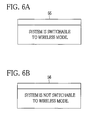
- the display control section 47b displays on the monitor 47a a window 55, which says that the communication mode is switchable to the wireless mode, as shown in Fig. 6A .
- the display control section 47b displays on the monitor 47a a window 56, which says that the communication mode is not switchable to the wireless mode, as shown in Fig. 6B .
- the first judging section 51 measures the charge level of the battery 36 (S13), and judges whether or not the charge level of the battery 36 exceeds the predetermined threshold value (S14).
- the second judging section 52 judges whether or not the radiography, which is carried out on a patient-by-patient basis, is in progress (S15) . If it is judged that the radiography is not in progress (NO in S15), the window 55 (see Fig. 6A ) saying that the communication mode is switchable to the wireless mode is displayed on the monitor 47a (S16).
- the second judging section 52 judges whether or not the radiography is in progress (S17). If it is judged that the radiography is not in progress (NO in S17), the window 56 (see Fig. 6B ) saying that the communication mode is not switchable to the wireless mode is displayed on the monitor 47a (S18).
- the second judging section 52 judges whether or not the radiography is in progress. If the radiography is not judged to be in progress, the window 55 indicating permission for switching to the wireless mode is displayed on the monitor 47a, on which the radiographic image is to be displayed. Thus, it is possible to notify the doctor of the permission for switching at an appropriate time without interrupting checking operation of the radiographic image. This does not impose an inconvenience on the doctor. Also, the doctor is easily notified of the permission, and does not miss a chance to switch to the wireless mode.
- the radiography is not judged to be in progress at the time of completing transmission of all the image data of the single order (single patient), in other words, at the time of completing the checking operation of the radiographic image, and then the window 55 is displayed on the monitor 47a.
- the permission for switching to the wireless mode while the doctor is watching the monitor 47a.
- the doctor is not busy during the time from completion of the radiography of one patient until starting the radiography of the next patient. Therefore, the doctor can efficiently switch the cassette 13 to the wireless mode with sufficient time.
- the notification of the permission or prohibition of switching to the wireless mode is made in consideration of a communication condition in the wireless mode, in addition to the charge level of the battery 36.
- the same structure, operation, and effect as those of the first embodiment will be omitted.
- the first judging section 51 checks the communication condition (for example, communication signal strength) between the cassette 13 and the console device 14 in the wireless mode, in order to judge whether or not the communication condition is good enough for sending the image data.
- the communication condition for example, communication signal strength
- the display control section 47b displays the window 55 as shown in Fig. 6A on the monitor 47a.
- the display control section 47b displays the window 56 as shown in Fig. 6B on the monitor 47a.
- S21 to S25 are the same as S11 to S15.
- the first judging section 51 checks the radio signal strength communicated between the cassette 13 and the console device 14, to judge whether or not the communication condition is good enough for sending the image data (S26).
- the window 55 (see Fig. 6A ) indicating the permission for switching to the wireless mode is displayed on the monitor 47a (S27).
- the window 56 (see Fig. 6B ) indicating the prohibition against switching to the wireless mode is displayed on the monitor 47a (S29).
- the console controller 42 of the console device 14 includes the first and second judging sections 51 and 52.
- the cassette controller 33 of the cassette 13 may function as similar judging sections.
- the doctor is notified of the permission for switching to the wireless mode by the window 55 displayed on the monitor 47a, but may be notified by blinking the monitor lamp 28 provided in the cassette 13 or a monitor lamp (not illustrated) provided in the console device 14, or by outputting sound from a speaker (not illustrated) additionally provided in the console device 14.
- the status is changed to "finished”, upon completion of sending all the image data of the single order.
- the status may be changed to "finished” whenever the radiography of each image is completed.
- the window 55 indicating the permission for switching to the wireless mode may be displayed on the monitor 47a. This facilitates early return to the wireless mode.
- the present invention is applied to the X-ray imaging system using the X-rays as the radiation, but the present invention is applicable to the other types of radiation imaging systems using gamma rays, alpha rays, or the like.
Landscapes
- Health & Medical Sciences (AREA)
- Life Sciences & Earth Sciences (AREA)
- Engineering & Computer Science (AREA)
- Medical Informatics (AREA)
- Heart & Thoracic Surgery (AREA)
- Molecular Biology (AREA)
- Biophysics (AREA)
- Nuclear Medicine, Radiotherapy & Molecular Imaging (AREA)
- Optics & Photonics (AREA)
- Pathology (AREA)
- Radiology & Medical Imaging (AREA)
- Biomedical Technology (AREA)
- Physics & Mathematics (AREA)
- High Energy & Nuclear Physics (AREA)
- Surgery (AREA)
- Animal Behavior & Ethology (AREA)
- General Health & Medical Sciences (AREA)
- Public Health (AREA)
- Veterinary Medicine (AREA)
- Multimedia (AREA)
- Signal Processing (AREA)
- Computer Networks & Wireless Communication (AREA)
- Apparatus For Radiation Diagnosis (AREA)
- Radiography Using Non-Light Waves (AREA)
Applications Claiming Priority (1)
| Application Number | Priority Date | Filing Date | Title |
|---|---|---|---|
| JP2010058608A JP5436281B2 (ja) | 2010-03-16 | 2010-03-16 | 放射線撮影システム、コンソール、放射線撮影用カセッテ、及びプログラム |
Publications (2)
| Publication Number | Publication Date |
|---|---|
| EP2374412A2 true EP2374412A2 (de) | 2011-10-12 |
| EP2374412A3 EP2374412A3 (de) | 2012-05-02 |
Family
ID=44511728
Family Applications (1)
| Application Number | Title | Priority Date | Filing Date |
|---|---|---|---|
| EP20110151783 Ceased EP2374412A3 (de) | 2010-03-16 | 2011-01-24 | Strahlungsabbildungssystem mit Strahlungsabbildungskartusche und Konsolenvorrichtung und Strahlungsabbildungsprogramm |
Country Status (4)
| Country | Link |
|---|---|
| US (1) | US8576087B2 (de) |
| EP (1) | EP2374412A3 (de) |
| JP (1) | JP5436281B2 (de) |
| CN (1) | CN102188254B (de) |
Families Citing this family (17)
| Publication number | Priority date | Publication date | Assignee | Title |
|---|---|---|---|---|
| JP2012239814A (ja) * | 2011-05-24 | 2012-12-10 | Fujifilm Corp | 放射線撮影装置 |
| JP6021403B2 (ja) * | 2012-04-19 | 2016-11-09 | キヤノン株式会社 | 放射線撮像装置 |
| JP6050206B2 (ja) * | 2013-09-17 | 2016-12-21 | 富士フイルム株式会社 | 放射線撮影システム及び通信環境制御装置 |
| JP6251147B2 (ja) * | 2014-09-29 | 2017-12-20 | 富士フイルム株式会社 | 電子カセッテおよび電子カセッテの作動方法 |
| JP6525576B2 (ja) * | 2014-12-17 | 2019-06-05 | キヤノン株式会社 | 制御装置、制御システム、制御方法、医用画像撮影装置、医用画像撮影システム、撮影制御方法およびプログラム |
| JP6668716B2 (ja) * | 2015-12-04 | 2020-03-18 | コニカミノルタ株式会社 | 移動型放射線撮影装置 |
| JP6988937B2 (ja) * | 2015-12-04 | 2022-01-05 | コニカミノルタ株式会社 | 移動型放射線撮影装置 |
| JP6687394B2 (ja) * | 2016-01-18 | 2020-04-22 | キヤノンメディカルシステムズ株式会社 | X線診断装置及びx線検出器 |
| JP6618378B2 (ja) * | 2016-02-09 | 2019-12-11 | キヤノン株式会社 | X線撮影装置およびその制御方法 |
| CN106562798B (zh) * | 2016-10-25 | 2023-07-28 | 上海奕瑞光电子科技股份有限公司 | 平板探测器系统及其快速配置和影像导出的方法 |
| CN106667548A (zh) * | 2017-02-28 | 2017-05-17 | 重庆西山科技股份有限公司 | 基于无线控制的超声手术系统 |
| JP6980456B2 (ja) * | 2017-08-22 | 2021-12-15 | キヤノン株式会社 | 放射線撮像システム |
| JP7071095B2 (ja) * | 2017-11-15 | 2022-05-18 | キヤノン株式会社 | 放射線撮像装置 |
| JP2019126523A (ja) * | 2018-01-24 | 2019-08-01 | コニカミノルタ株式会社 | 放射線撮影装置及び放射線撮影システム |
| JP2020198470A (ja) * | 2019-05-30 | 2020-12-10 | ソニーセミコンダクタソリューションズ株式会社 | 画像認識装置および画像認識方法 |
| CN112947222A (zh) * | 2021-03-03 | 2021-06-11 | 纳米维景(上海)医疗科技有限公司 | Ct机无线控制系统、存储介质及ct机无线控制装置 |
| CN113726608B (zh) * | 2021-08-30 | 2022-11-22 | 阿波罗智联(北京)科技有限公司 | 数据处理方法及装置 |
Citations (2)
| Publication number | Priority date | Publication date | Assignee | Title |
|---|---|---|---|---|
| JP2005006979A (ja) | 2003-06-19 | 2005-01-13 | Canon Inc | 放射線撮像装置、放射線撮像方法、及び、放射線撮像プログラム |
| JP2009297187A (ja) | 2008-06-12 | 2009-12-24 | Konica Minolta Medical & Graphic Inc | 放射線画像撮影システム |
Family Cites Families (22)
| Publication number | Priority date | Publication date | Assignee | Title |
|---|---|---|---|---|
| JPH0549058A (ja) * | 1991-08-16 | 1993-02-26 | Fujitsu Ltd | リソース整合処理方式 |
| JPH09139725A (ja) * | 1995-11-16 | 1997-05-27 | Matsushita Electric Ind Co Ltd | 多重通信装置 |
| US5650623A (en) * | 1995-12-04 | 1997-07-22 | General Electric Company | Perimeter sensing device |
| JP3247987B2 (ja) * | 2000-03-27 | 2002-01-21 | 忠男 趙 | 放射線測定警報システム |
| US7041512B2 (en) * | 2001-06-07 | 2006-05-09 | Advantest Corp. | Electron beam exposure apparatus, electron beam exposing method, semiconductor element manufacturing method, and pattern error detection method |
| JP2004298225A (ja) * | 2003-03-28 | 2004-10-28 | Konica Minolta Holdings Inc | 医用画像撮影システム |
| US7237719B2 (en) * | 2003-09-03 | 2007-07-03 | Stmicroelectronics, Inc. | Method and apparatus for a USB and contactless smart card device |
| JP2005208269A (ja) * | 2004-01-22 | 2005-08-04 | Canon Inc | 無線電子カセッテおよび無線電子カセッテを使ったx線撮影システム |
| JP2005323732A (ja) * | 2004-05-13 | 2005-11-24 | Konica Minolta Medical & Graphic Inc | 放射線画像検出装置及び放射線画像撮影システム |
| WO2006003776A1 (ja) * | 2004-06-04 | 2006-01-12 | Matsushita Electric Industrial Co., Ltd. | 無線通信装置 |
| JP2007127414A (ja) * | 2004-07-21 | 2007-05-24 | Konica Minolta Medical & Graphic Inc | 放射線画像検出器及び放射線画像撮影システム |
| JP2008134057A (ja) * | 2005-03-10 | 2008-06-12 | Konica Minolta Medical & Graphic Inc | 放射線画像検出器及び放射線画像撮影システム |
| JP4649348B2 (ja) * | 2006-02-28 | 2011-03-09 | 株式会社日立製作所 | 核医学診断装置 |
| US7787594B2 (en) * | 2007-07-26 | 2010-08-31 | Fujifilm Corporation | Radiation image capturing method, radiation image capturing system and radiation information system for carrying out radiation image capturing method |
| EP2022393A3 (de) * | 2007-07-30 | 2011-03-02 | FUJIFILM Corporation | Strahlungsdetektionskassette und medizinisches System |
| JP4444348B2 (ja) | 2007-08-16 | 2010-03-31 | 富士フイルム株式会社 | 放射線検出カセッテ及び放射線画像撮影システム |
| JP5438903B2 (ja) * | 2008-01-28 | 2014-03-12 | 富士フイルム株式会社 | 放射線検出装置及び放射線画像撮影システム |
| TWI363494B (en) * | 2008-04-09 | 2012-05-01 | Mstar Semiconductor Inc | Radio frequency identification tag and operating method thereof |
| JP5512105B2 (ja) * | 2008-08-20 | 2014-06-04 | 富士フイルム株式会社 | 可搬型放射線検出器 |
| FI20086241A7 (fi) * | 2008-12-23 | 2010-06-24 | Palodex Group Oy | Kuvalevyn lukijalaite |
| US7909511B2 (en) * | 2009-03-16 | 2011-03-22 | Carestream Health, Inc. | Tray for portable digital radiography cassette |
| JP2012165918A (ja) * | 2011-02-15 | 2012-09-06 | Fujifilm Corp | 放射線画像撮影装置、及び通信モード設定装置 |
-
2010
- 2010-03-16 JP JP2010058608A patent/JP5436281B2/ja active Active
-
2011
- 2011-01-20 US US12/929,378 patent/US8576087B2/en active Active
- 2011-01-24 EP EP20110151783 patent/EP2374412A3/de not_active Ceased
- 2011-01-31 CN CN201110034146.4A patent/CN102188254B/zh active Active
Patent Citations (2)
| Publication number | Priority date | Publication date | Assignee | Title |
|---|---|---|---|---|
| JP2005006979A (ja) | 2003-06-19 | 2005-01-13 | Canon Inc | 放射線撮像装置、放射線撮像方法、及び、放射線撮像プログラム |
| JP2009297187A (ja) | 2008-06-12 | 2009-12-24 | Konica Minolta Medical & Graphic Inc | 放射線画像撮影システム |
Also Published As
| Publication number | Publication date |
|---|---|
| US20110227750A1 (en) | 2011-09-22 |
| CN102188254B (zh) | 2014-09-03 |
| US8576087B2 (en) | 2013-11-05 |
| JP5436281B2 (ja) | 2014-03-05 |
| EP2374412A3 (de) | 2012-05-02 |
| JP2011189033A (ja) | 2011-09-29 |
| CN102188254A (zh) | 2011-09-21 |
Similar Documents
| Publication | Publication Date | Title |
|---|---|---|
| US8576087B2 (en) | Radiation imaging system having radiation imaging cassette and console device, and radiation imaging program | |
| EP1921466A2 (de) | Röntgendurchleuchtungssystem für Strahlungsbilder und Strahlungsbilderkennungsvorrichtung | |
| EP2977010B1 (de) | Strahlungsbild-erfassungssystem für interferenzvermeidung beim benutzen von drahtlosen signalen zwischen bilderfassungsgerät, konsole und krankenhaus informationssystem | |
| JP5167966B2 (ja) | 放射線画像撮影システム及び放射線画像検出器 | |
| EP2759264A1 (de) | Radiographisches system, kommunikationsverfahren für das radiographische system und radiographenerkennungsausrüstung | |
| JP2007127414A (ja) | 放射線画像検出器及び放射線画像撮影システム | |
| CN101146481B (zh) | 放射线拍照成像系统 | |
| JP2008142094A (ja) | 放射線画像取得装置及び放射線画像撮影システム | |
| JP2012157666A (ja) | 放射線画像撮影システム | |
| EP2375727B1 (de) | Strahlungsabbildungssystem, Konsole und Strahlungsabbildungsprogramm | |
| JP7501456B2 (ja) | 放射線撮影システム、プログラム及び制御端末 | |
| JP5707869B2 (ja) | 放射線画像撮影システム | |
| JP7163797B2 (ja) | 充電制御装置及び移動型放射線撮影システム | |
| JP2010022752A (ja) | 医用画像システム | |
| JP6361748B2 (ja) | 移動型x線撮影装置 | |
| JP2010012060A (ja) | 可搬型放射線画像検出器および放射線画像撮影システム | |
| JP2006115917A (ja) | 放射線検出システム及び放射線検出器 | |
| JP2006116205A (ja) | 放射線撮影システム | |
| JP2020078616A (ja) | 移動型放射線撮影装置 | |
| US20240385341A1 (en) | Radiographic imaging apparatus and radiographic imaging system | |
| WO2011046049A1 (ja) | 放射線画像撮影システム | |
| US20230181135A1 (en) | Radiographic imaging device and radiography system | |
| EP4417130A1 (de) | Röntgenvorrichtung und röntgensystem | |
| JP7238693B2 (ja) | 放射線撮影装置、放射線撮影システム及びプログラム | |
| JP2006081729A (ja) | 放射線撮影システム |
Legal Events
| Date | Code | Title | Description |
|---|---|---|---|
| PUAI | Public reference made under article 153(3) epc to a published international application that has entered the european phase |
Free format text: ORIGINAL CODE: 0009012 |
|
| AK | Designated contracting states |
Kind code of ref document: A2 Designated state(s): AL AT BE BG CH CY CZ DE DK EE ES FI FR GB GR HR HU IE IS IT LI LT LU LV MC MK MT NL NO PL PT RO RS SE SI SK SM TR |
|
| AX | Request for extension of the european patent |
Extension state: BA ME |
|
| PUAL | Search report despatched |
Free format text: ORIGINAL CODE: 0009013 |
|
| AK | Designated contracting states |
Kind code of ref document: A3 Designated state(s): AL AT BE BG CH CY CZ DE DK EE ES FI FR GB GR HR HU IE IS IT LI LT LU LV MC MK MT NL NO PL PT RO RS SE SI SK SM TR |
|
| AX | Request for extension of the european patent |
Extension state: BA ME |
|
| RIC1 | Information provided on ipc code assigned before grant |
Ipc: H04N 5/32 20060101ALI20120329BHEP Ipc: A61B 6/00 20060101AFI20120329BHEP |
|
| 17P | Request for examination filed |
Effective date: 20121016 |
|
| 17Q | First examination report despatched |
Effective date: 20130503 |
|
| STAA | Information on the status of an ep patent application or granted ep patent |
Free format text: STATUS: THE APPLICATION HAS BEEN REFUSED |
|
| 18R | Application refused |
Effective date: 20161124 |