EP2365291A1 - Fotoelektrischer Kodierer - Google Patents
Fotoelektrischer Kodierer Download PDFInfo
- Publication number
- EP2365291A1 EP2365291A1 EP11000325A EP11000325A EP2365291A1 EP 2365291 A1 EP2365291 A1 EP 2365291A1 EP 11000325 A EP11000325 A EP 11000325A EP 11000325 A EP11000325 A EP 11000325A EP 2365291 A1 EP2365291 A1 EP 2365291A1
- Authority
- EP
- European Patent Office
- Prior art keywords
- points
- light
- period
- sin
- cos
- Prior art date
- Legal status (The legal status is an assumption and is not a legal conclusion. Google has not performed a legal analysis and makes no representation as to the accuracy of the status listed.)
- Granted
Links
- 238000000034 method Methods 0.000 claims abstract description 20
- 230000007547 defect Effects 0.000 claims abstract description 18
- 238000010586 diagram Methods 0.000 description 14
- 238000001514 detection method Methods 0.000 description 10
- 238000004364 calculation method Methods 0.000 description 7
- 238000005259 measurement Methods 0.000 description 7
- 230000003287 optical effect Effects 0.000 description 6
- 230000000903 blocking effect Effects 0.000 description 2
- 230000008859 change Effects 0.000 description 1
- 230000004069 differentiation Effects 0.000 description 1
- 230000000694 effects Effects 0.000 description 1
- 238000012886 linear function Methods 0.000 description 1
- 230000007257 malfunction Effects 0.000 description 1
- 230000004048 modification Effects 0.000 description 1
- 238000012986 modification Methods 0.000 description 1
- 239000004065 semiconductor Substances 0.000 description 1
- 239000000758 substrate Substances 0.000 description 1
Images


Classifications
-
- G—PHYSICS
- G01—MEASURING; TESTING
- G01D—MEASURING NOT SPECIALLY ADAPTED FOR A SPECIFIC VARIABLE; ARRANGEMENTS FOR MEASURING TWO OR MORE VARIABLES NOT COVERED IN A SINGLE OTHER SUBCLASS; TARIFF METERING APPARATUS; MEASURING OR TESTING NOT OTHERWISE PROVIDED FOR
- G01D5/00—Mechanical means for transferring the output of a sensing member; Means for converting the output of a sensing member to another variable where the form or nature of the sensing member does not constrain the means for converting; Transducers not specially adapted for a specific variable
- G01D5/12—Mechanical means for transferring the output of a sensing member; Means for converting the output of a sensing member to another variable where the form or nature of the sensing member does not constrain the means for converting; Transducers not specially adapted for a specific variable using electric or magnetic means
- G01D5/244—Mechanical means for transferring the output of a sensing member; Means for converting the output of a sensing member to another variable where the form or nature of the sensing member does not constrain the means for converting; Transducers not specially adapted for a specific variable using electric or magnetic means influencing characteristics of pulses or pulse trains; generating pulses or pulse trains
- G01D5/24471—Error correction
- G01D5/24476—Signal processing
Definitions
- the present invention relates to a photoelectric encoder including a scale in which a grating is formed with a predetermined period, a light source and a light receiving unit which are movable relative to the scale.
- the present invention particularly relates to a photoelectric encoder suitable for use as a linear encoder and capable of reducing occurrence of a position detecting error due to stain on the scale or a defect of the grating through simple computing.
- a photoelectric encoder has been utilized for precisely measuring an amount of linear movement of an object to be measured.
- An arctangent calculation of Lissajous signals obtained from a light receiving element array is one of the position sensing methods often employed for an optical encoder.
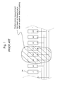
- Patent Document 1 In a method proposed in Japanese Patent Application Publication No. Sho 64-57120 (Patent Document 1), for example, firstly light receiving elements made of P-type semiconductor layers 34 respectively forming photosensitive zones 35 are arranged in an array at a pitch having a phase difference from the phase of an optical grating 12 of a scale 13, as shown in Figs. 1 and 2 of Patent Document 1. Next, differential amplifiers 38A and 38B each amplify a difference between output signals from the light receiving elements to generate a Lissajous signal. Further, an arctangent calculation is performed on the Lissajous signals, so that a position is detected.
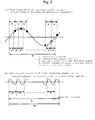
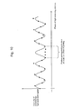
- the scale when the scale is adhered by stain or has a grating defect as shown in Fig. 1 of the present application, some of measurement light beams which should reach the light receiving elements 34 is blocked by the stain or the grating defect that varies in size, the light receiving elements 34 output unbalanced signals.
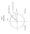
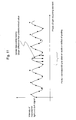
- the light receiving elements 34 When the light receiving elements 34 output the unbalanced signals, a direct current component of the Lissajous signal is offset from a normal position shown by a solid line in Fig. 2 to a position shown by a broken line therein. This causes a problem of an error in position detection using the arctangent calculation.
- the photoelectric encoder includes: a scale in which a grating is formed with a predetermined period; and a sensor head which has a light source and a light receiving unit and which is movable relative to the scale.
- N is an integer of 3 or more.
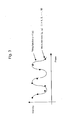
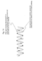
- a sinusoidal function with fixed period is fitted to N-points digital signals digitized from the N-points light and dark signals, as illustrated in Fig. 3 .
- the phases of the N-points light and dark signals are detected.
- This technique is expected to improve accuracy in comparison with a method in which computing is performed on only edges, because this method performs computing on all the imaged points.
- a large amount of computing in the technique involves a long computing time. This requires a high-performance signal processing circuit, thus causing a problem of a high cost.
- An object of the invention is to reduce a cost by speeding up computing for deriving a model sinusoidal function with use of a least-squares method and thereby by making the computing applicable to even an inexpensive processing circuit.
- equations (9) are substituted into the equations (2), and thereby the parameters A, B and C can be obtained as in the following equations:
- the equations (10) may be transformed into the following equations in consideration that the calculation needs only a ratio of sin(-B) to cos(-B):
- the present invention is made applicable by the following processing: a.
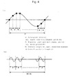
- the data-point interval w can be adjusted to a data-point interval w' in any manner of performing interpolation for N-points light and dark signals by generating new data points, i.e., by interpolating an intermediate data point within each data-point interval w so that the N-points light and dark signal period P can be an integral multiple of the data-point interval w, as illustrated in Fig. 5A ; or b.
- the overall analysis length L can be adjusted exactly to a desired length by truncating the overall length M of the light receiving element so that the overall analysis length L can be an integral multiple of the N-points light and dark signal period P, as illustrated in Fig. 5B .
- the present invention has been made based on the aforementioned technical findings, and solves the above problems by providing a photoelectric encoder including: a scale in which a grating is formed with a predetermined period Ps; and a detector head which is movable relative to the scale and which includes a light source and a light receiving unit.
- N is an integer of 3 or more
- phases of the N-points light and dark signals are detected by performing a least-squares method to fit a sinusoidal function with fixed period to N-points digital signals respectively digitized from the N-points light and dark signals
- a period P of the N-points light and dark signals is set at an integral multiple of a data-point interval w of the N-points digital signals
- an overall length M of the light receiving elements is set at an integral multiple of the period P of the N-points light and dark signals.
- data points may be generated by performing interpolation for the data-point interval w of the N-points digital signals so that the period P of the N-points light and dark signals is an integral multiple of the data-point interval w of the N-points digital signals, as illustrated in Fig. 5A .
- an overall analysis length L may be adjusted by truncating the overall length M of the light receiving elements so that the overall analysis length L is an integral multiple of the period P of the N-points light and dark signals, as illustrated in Fig. 5B .
- the period P of the N-points light and dark signals may be equalized to the scale period Ps.
- the data-point interval w of the N-points digital signals may be made to correspond a pitch Pd of the light receiving elements.
- stain on the scale or a defect of the grating may be detected based on the N-points light and dark signals.
- a point corresponding to the stain on the scale or the defect of the grating may be excluded from fitting target points, and thereafter the fitting may be performed again.
- an accidental error in position detecting may be detected when an amplitude A of the sinusoidal function is smaller than a predetermined threshold.
- computing time required for fitting of a sinusoidal function can be significantly reduced by reducing an amount of least-squares method-based computing for deriving a model function of sinusoidal wave with fixed period.
- the configuration of the present invention is more likely to prevent light receiving elements in the same phase from suffering selective blocking of light beams, unlike the prior art in Patent Document 1.
- this configuration more frequently prevents position detecting from becoming impossible and thereby enables continuous position detecting.
- the arctangent calculation is not performed in which an error occurs due to the direct current offset of the Lissajous signal, as shown in Fig. 2 .
- an error is less likely to occur in the position detecting.
- the present invention exerts excellent advantageous effects, such as avoiding aliasing in which a wrong period is detected.
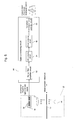
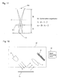
- Fig. 6 shows an outline of an overall configuration of a first embodiment of a photoelectric encoder according to the present invention.
- the photoelectric encoder includes: a detector head 20 provided with a scale 13, a light emitting element 14, a collimator lens 17 and a light receiving unit 30 equipped with light receiving elements 34 arranged in an array; and a signal processing circuit 60.
- a detector head 20 provided with a scale 13, a light emitting element 14, a collimator lens 17 and a light receiving unit 30 equipped with light receiving elements 34 arranged in an array; and a signal processing circuit 60.
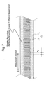
- an incremental pattern with a period (scale period) Ps is formed as a grating 12 on a transparent substrate 11, as shown in Fig. 7 .
- the light emitting element 14 is a light source which emits measurement light beams.
- the collimator lens 17 collimates the measurement light beams.
- the signal processing circuit 60 outputs position signals by processing output signals from the light receiving elements 34.
- the scale 13 is movable in
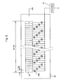
- the light receiving unit 30 includes N light receiving elements 34 (N is an integer of 3 or more, for example, 1024 elements) arranged in an array at constant intervals (light-receiving-element pitch) Pd corresponding to data-point intervals w, and outputs light and dark signals of N-pointss (for example, 1024 phases) through a preamplifier 37.
- N-points light and dark signals are generated in such a way that: the light receiving elements 34 output signals by photoelectrically converting incident measurement light beams; and then switching elements 34a sweep the output signals from the light receiving elements 34.
- selective malfunction of the light receiving elements in the same phase makes the position detecting impossible.
- all the light receiving elements equally function, and thus the position detecting is less likely to become impossible.
- a distance A between the collimator lens 17 and the scale 13 is set equal to a distance B between the collimator lens 17 and the light-receiving elements 34 as later shown in Fig. 15 .
- an optical system magnification m is equal to 1, so that an N-points light and dark signal period P is equalized to a scale period Ps.
- N-points light and dark signals are firstly noise-filtered by a noise filter amplifier circuit 62, are then amplified at a predetermined gain, and thereafter are analog-digitally converted by an A/D converter circuit 64. Subsequently, phases of the scale 13 are detected by a phase detection circuit 66, and then two-phase rectangular waves are outputted as position signals from a two-phase rectangular wave generator circuit 68 to a counter circuit or the like, for example.
- the phase detection circuit 66 performs the fitting on the digitized N-points light and dark signals by the least-squares method using as a model of the aforementioned equation (1) which is a sinusoidal function with a fixed period. Thereby, the phase detection circuit 66 detects the phases of the N-points light and dark signals.
- a horizontal axis represents a phase and a vertical axis represents intensity, as shown in Fig. 3 .
- N data points (x i , y i ) are targeted for the fitting, and a fitting function is f(x).
- the scale position can be detected.
- the least-squares method is applied by using a non-linear function as a model, a unique solution cannot be obtained.
- the period of the sinusoidal function is fixed, a unique solution can exceptionally be obtained.
- Fig. 10 a description is given of a case where the scale 13 is adhered by stain or has a defect in the grating 12.
- the intensity of the light and dark signals outputted by the light receiving elements 34 is lowered at a point corresponding to the stain on the scale or the defect of the grating, the light receiving elements in the same phase do not suffer from selective blocking of light beams.
- the arctangent calculation is not performed in which an error occurs due to the direct current offset of the Lissajous signal as shown in Fig. 2 .
- an error is less likely to occur in the position detecting.
- an amplitude A of the sinusoidal function takes a value near zero, as shown in Fig. 12 .
- an accidental error in position detecting can be detected by setting a predetermined threshold in advance.
- a detection of a point corresponding to stain of the scale 13 or a defect of the grating 12 can be outputted as an error.
- Methods usable for outputting an error are, for example, a method in which the phase detection circuit 66 outputs an error signal as shown in Fig. 13A , and a method in which the two-phase rectangular wave generator circuit 68 outputs the rectangular waves with the phases matched with each other as shown in Fig. 13B .
- aliasing which is an error of detecting a period different from the period (scale period) Ps of the incremental pattern of the scale 13 as indicated by a broken line in Fig. 14 , can be avoided as indicated by the solid line by using the sinusoidal function with fixed period.
- the optical system magnification m is not limited to 1, but may be any magnification, as in a second embodiment shown in Fig. 15 , by setting different values as a distance A between a lens 17 and a scale 13 and a distance B between the lens 17 and light receiving elements 34.
- the optical system magnification m may be set at 0.5 as shown in Fig. 16 , or 2 as shown in Fig. 17 .
- reference letter f denotes a focal position of the lens 17.
- the data-point interval w corresponds to the light-receiving-element pitch Pd in the above-described embodiment.
- the present invention is also applicable to a reflection type photoelectric encoder as shown in Fig. 18 .
- the present invention is further applicable to even a rotary encoder as well as the linear encoder.
Landscapes
- Engineering & Computer Science (AREA)
- Signal Processing (AREA)
- Physics & Mathematics (AREA)
- General Physics & Mathematics (AREA)
- Optical Transform (AREA)
Applications Claiming Priority (1)
| Application Number | Priority Date | Filing Date | Title |
|---|---|---|---|
| JP2010029403A JP5641746B2 (ja) | 2010-02-12 | 2010-02-12 | 光電式エンコーダ |
Publications (2)
| Publication Number | Publication Date |
|---|---|
| EP2365291A1 true EP2365291A1 (de) | 2011-09-14 |
| EP2365291B1 EP2365291B1 (de) | 2012-10-24 |
Family
ID=44218340
Family Applications (1)
| Application Number | Title | Priority Date | Filing Date |
|---|---|---|---|
| EP11000325A Active EP2365291B1 (de) | 2010-02-12 | 2011-01-17 | Fotoelektrischer Kodierer |
Country Status (4)
| Country | Link |
|---|---|
| US (1) | US8325066B2 (de) |
| EP (1) | EP2365291B1 (de) |
| JP (1) | JP5641746B2 (de) |
| CN (1) | CN102168996B (de) |
Families Citing this family (10)
| Publication number | Priority date | Publication date | Assignee | Title |
|---|---|---|---|---|
| JP5964162B2 (ja) * | 2012-07-18 | 2016-08-03 | 株式会社ミツトヨ | エンコーダ |
| JP6169498B2 (ja) * | 2014-01-14 | 2017-07-26 | 株式会社神戸製鋼所 | 回転機器から得られた周期信号の位相及び振幅の推定装置 |
| DE112015001644T8 (de) | 2014-04-04 | 2017-01-19 | Citizen Finedevice Co., Ltd. | Zylinderinnendruckerfassungsvorrichtung |
| JP5956532B2 (ja) * | 2014-04-21 | 2016-07-27 | 本田技研工業株式会社 | 筒内圧検出装置 |
| WO2015151994A1 (ja) * | 2014-04-04 | 2015-10-08 | 本田技研工業株式会社 | 筒内圧検出装置 |
| CN104613986B (zh) * | 2015-02-05 | 2017-05-24 | 哈尔滨工业大学 | 一种基于最小二乘法拟合曲线补偿光电编码器基准电压的方法 |
| US9871595B2 (en) | 2016-04-27 | 2018-01-16 | Industrial Technology Research Institute | Decoding device and method for absolute positioning code |
| JP2018194738A (ja) * | 2017-05-19 | 2018-12-06 | キヤノン株式会社 | 位置計測装置、リソグラフィ装置、および物品製造方法 |
| CN109388080B (zh) * | 2017-08-04 | 2021-05-28 | 佛山市顺德区美的电热电器制造有限公司 | 编码器开关的控制方法、装置及电器设备 |
| JP7252809B2 (ja) * | 2019-03-28 | 2023-04-05 | 株式会社ミツトヨ | 光電式エンコーダおよび光電式エンコーダにおける演算方法 |
Citations (6)
| Publication number | Priority date | Publication date | Assignee | Title |
|---|---|---|---|---|
| US4524347A (en) * | 1980-05-15 | 1985-06-18 | Ferranti Limited | Position encoder |
| JPS6457120A (en) | 1987-08-26 | 1989-03-03 | Mitutoyo Corp | Optical displacement detector |
| US5021650A (en) * | 1989-03-29 | 1991-06-04 | Rsf-Elektronik Gesellschaft M.B.H. | Method of electronically correcting position errors in an incremental measuring system and measuring system for carrying out the method |
| US5889280A (en) * | 1996-01-23 | 1999-03-30 | Mitutoyo Corporation | Apparatus for measuring displacement |
| JP2010029403A (ja) | 2008-07-29 | 2010-02-12 | Universal Entertainment Corp | 遊技機 |
| US20100044551A1 (en) * | 2008-08-20 | 2010-02-25 | Mitutoyo Corporation | Photoelectric encoder |
Family Cites Families (11)
| Publication number | Priority date | Publication date | Assignee | Title |
|---|---|---|---|---|
| DE3239108A1 (de) * | 1982-10-22 | 1984-04-26 | Dr. Johannes Heidenhain Gmbh, 8225 Traunreut | Positionsmessverfahren und einrichtungen zur durchfuehrung des verfahrens |
| JPS6166113A (ja) * | 1984-09-07 | 1986-04-04 | Mitsutoyo Mfg Co Ltd | 変位検出装置の異常検出方法及び回路 |
| JPH0587594A (ja) * | 1991-09-26 | 1993-04-06 | Yokogawa Electric Corp | 光学式エンコーダ |
| ATE229642T1 (de) * | 1997-08-07 | 2002-12-15 | Heidenhain Gmbh Dr Johannes | Abtasteinheit für eine optische positionsmesseinrichtung |
| JP2005337843A (ja) * | 2004-05-26 | 2005-12-08 | Canon Inc | 光学式エンコーダ |
| JP4054817B2 (ja) * | 2004-08-20 | 2008-03-05 | シャープ株式会社 | 光学式エンコーダおよびそれを用いた電子機器 |
| JP5286524B2 (ja) * | 2006-03-22 | 2013-09-11 | 国立大学法人群馬大学 | 周波数測定装置及び周波数測定方法 |
| US7265339B1 (en) * | 2006-05-22 | 2007-09-04 | Avago Technologies General Ip (Singapore) Pte. Ltd. | Encoder interpolation apparatus |
| JP4824635B2 (ja) * | 2007-06-15 | 2011-11-30 | 株式会社 ソキア・トプコン | ロータリエンコーダの角度補正方法 |
| JP5286584B2 (ja) * | 2007-06-19 | 2013-09-11 | 株式会社ミツトヨ | 絶対位置測長型エンコーダ |
| JP5103267B2 (ja) * | 2008-05-13 | 2012-12-19 | 株式会社ミツトヨ | 絶対位置測長型エンコーダ |
-
2010
- 2010-02-12 JP JP2010029403A patent/JP5641746B2/ja active Active
-
2011
- 2011-01-04 CN CN201110000209.4A patent/CN102168996B/zh active Active
- 2011-01-17 EP EP11000325A patent/EP2365291B1/de active Active
- 2011-02-11 US US13/025,198 patent/US8325066B2/en active Active
Patent Citations (6)
| Publication number | Priority date | Publication date | Assignee | Title |
|---|---|---|---|---|
| US4524347A (en) * | 1980-05-15 | 1985-06-18 | Ferranti Limited | Position encoder |
| JPS6457120A (en) | 1987-08-26 | 1989-03-03 | Mitutoyo Corp | Optical displacement detector |
| US5021650A (en) * | 1989-03-29 | 1991-06-04 | Rsf-Elektronik Gesellschaft M.B.H. | Method of electronically correcting position errors in an incremental measuring system and measuring system for carrying out the method |
| US5889280A (en) * | 1996-01-23 | 1999-03-30 | Mitutoyo Corporation | Apparatus for measuring displacement |
| JP2010029403A (ja) | 2008-07-29 | 2010-02-12 | Universal Entertainment Corp | 遊技機 |
| US20100044551A1 (en) * | 2008-08-20 | 2010-02-25 | Mitutoyo Corporation | Photoelectric encoder |
Non-Patent Citations (1)
| Title |
|---|
| DAISUKE TAKAHASHI, FUNDAMENTAL MATHEMATICS OF SCIENCE AND ENGINEERING, NUMERICAL CALCULATION, pages 52 - 54 |
Also Published As
| Publication number | Publication date |
|---|---|
| US8325066B2 (en) | 2012-12-04 |
| US20110199240A1 (en) | 2011-08-18 |
| JP5641746B2 (ja) | 2014-12-17 |
| CN102168996B (zh) | 2015-01-28 |
| EP2365291B1 (de) | 2012-10-24 |
| JP2011164029A (ja) | 2011-08-25 |
| CN102168996A (zh) | 2011-08-31 |
Similar Documents
| Publication | Publication Date | Title |
|---|---|---|
| EP2365291B1 (de) | Fotoelektrischer Kodierer | |
| US7994470B2 (en) | Photoelectric encoder | |
| JP5286584B2 (ja) | 絶対位置測長型エンコーダ | |
| JP5829464B2 (ja) | 絶対測長型エンコーダ | |
| EP1980824A1 (de) | Kodierer mit absoluter Positionslängenmessung | |
| EP2439498B1 (de) | Codierer | |
| CN105806372A (zh) | 编码器 | |
| EP1903314B1 (de) | Nullpunktfeststellungsverfahren für optischen Kodierer | |
| US9200928B2 (en) | Position detector | |
| US9574910B2 (en) | Position detecting apparatus, and lens apparatus and image pickup apparatus including the position detecting apparatus | |
| EP2405241A1 (de) | Absolutkodierer | |
| JP2006003126A (ja) | 光学式エンコーダ | |
| EP2110645B1 (de) | Absolutpositionscodierer vom Längsmessungstyp | |
| EP2369304B1 (de) | Fotoelektrischer Kodierer | |
| JP5553667B2 (ja) | 光学式基準位置検出型エンコーダ | |
| JP5824342B2 (ja) | リニアエンコーダ | |
| EP2587226B1 (de) | Vorrichtung und Verfahren zur Verschiebungserkennung | |
| JP2009047595A (ja) | 絶対位置測長型エンコーダ | |
| JP5553669B2 (ja) | 光学式絶対位置測長型エンコーダ | |
| EP2733469B1 (de) | Messvorrichtung, Messverfahren, und Absolutpositionsgeber | |
| US20150338239A1 (en) | Absolute encoder | |
| JP6694722B2 (ja) | 光学式エンコーダ及びその原点決定方法 | |
| JP6196539B2 (ja) | 光学式エンコーダ | |
| JP2014098666A (ja) | インクリメンタルエンコーダ |
Legal Events
| Date | Code | Title | Description |
|---|---|---|---|
| PUAI | Public reference made under article 153(3) epc to a published international application that has entered the european phase |
Free format text: ORIGINAL CODE: 0009012 |
|
| AK | Designated contracting states |
Kind code of ref document: A1 Designated state(s): AL AT BE BG CH CY CZ DE DK EE ES FI FR GB GR HR HU IE IS IT LI LT LU LV MC MK MT NL NO PL PT RO RS SE SI SK SM TR |
|
| AX | Request for extension of the european patent |
Extension state: BA ME |
|
| 17P | Request for examination filed |
Effective date: 20110811 |
|
| RIC1 | Information provided on ipc code assigned before grant |
Ipc: G01D 5/244 20060101AFI20120316BHEP |
|
| GRAP | Despatch of communication of intention to grant a patent |
Free format text: ORIGINAL CODE: EPIDOSNIGR1 |
|
| GRAS | Grant fee paid |
Free format text: ORIGINAL CODE: EPIDOSNIGR3 |
|
| GRAA | (expected) grant |
Free format text: ORIGINAL CODE: 0009210 |
|
| AK | Designated contracting states |
Kind code of ref document: B1 Designated state(s): AL AT BE BG CH CY CZ DE DK EE ES FI FR GB GR HR HU IE IS IT LI LT LU LV MC MK MT NL NO PL PT RO RS SE SI SK SM TR |
|
| REG | Reference to a national code |
Ref country code: GB Ref legal event code: FG4D |
|
| REG | Reference to a national code |
Ref country code: CH Ref legal event code: EP |
|
| REG | Reference to a national code |
Ref country code: AT Ref legal event code: REF Ref document number: 581174 Country of ref document: AT Kind code of ref document: T Effective date: 20121115 |
|
| REG | Reference to a national code |
Ref country code: IE Ref legal event code: FG4D |
|
| REG | Reference to a national code |
Ref country code: DE Ref legal event code: R096 Ref document number: 602011000330 Country of ref document: DE Effective date: 20121227 |
|
| REG | Reference to a national code |
Ref country code: AT Ref legal event code: MK05 Ref document number: 581174 Country of ref document: AT Kind code of ref document: T Effective date: 20121024 |
|
| REG | Reference to a national code |
Ref country code: NL Ref legal event code: VDEP Effective date: 20121024 |
|
| PG25 | Lapsed in a contracting state [announced via postgrant information from national office to epo] |
Ref country code: IS Free format text: LAPSE BECAUSE OF FAILURE TO SUBMIT A TRANSLATION OF THE DESCRIPTION OR TO PAY THE FEE WITHIN THE PRESCRIBED TIME-LIMIT Effective date: 20130224 Ref country code: FI Free format text: LAPSE BECAUSE OF FAILURE TO SUBMIT A TRANSLATION OF THE DESCRIPTION OR TO PAY THE FEE WITHIN THE PRESCRIBED TIME-LIMIT Effective date: 20121024 Ref country code: HR Free format text: LAPSE BECAUSE OF FAILURE TO SUBMIT A TRANSLATION OF THE DESCRIPTION OR TO PAY THE FEE WITHIN THE PRESCRIBED TIME-LIMIT Effective date: 20121024 Ref country code: NO Free format text: LAPSE BECAUSE OF FAILURE TO SUBMIT A TRANSLATION OF THE DESCRIPTION OR TO PAY THE FEE WITHIN THE PRESCRIBED TIME-LIMIT Effective date: 20130124 Ref country code: NL Free format text: LAPSE BECAUSE OF FAILURE TO SUBMIT A TRANSLATION OF THE DESCRIPTION OR TO PAY THE FEE WITHIN THE PRESCRIBED TIME-LIMIT Effective date: 20121024 Ref country code: SE Free format text: LAPSE BECAUSE OF FAILURE TO SUBMIT A TRANSLATION OF THE DESCRIPTION OR TO PAY THE FEE WITHIN THE PRESCRIBED TIME-LIMIT Effective date: 20121024 |
|
| PG25 | Lapsed in a contracting state [announced via postgrant information from national office to epo] |
Ref country code: PL Free format text: LAPSE BECAUSE OF FAILURE TO SUBMIT A TRANSLATION OF THE DESCRIPTION OR TO PAY THE FEE WITHIN THE PRESCRIBED TIME-LIMIT Effective date: 20121024 Ref country code: LV Free format text: LAPSE BECAUSE OF FAILURE TO SUBMIT A TRANSLATION OF THE DESCRIPTION OR TO PAY THE FEE WITHIN THE PRESCRIBED TIME-LIMIT Effective date: 20121024 Ref country code: GR Free format text: LAPSE BECAUSE OF FAILURE TO SUBMIT A TRANSLATION OF THE DESCRIPTION OR TO PAY THE FEE WITHIN THE PRESCRIBED TIME-LIMIT Effective date: 20130125 Ref country code: BE Free format text: LAPSE BECAUSE OF FAILURE TO SUBMIT A TRANSLATION OF THE DESCRIPTION OR TO PAY THE FEE WITHIN THE PRESCRIBED TIME-LIMIT Effective date: 20121024 Ref country code: SI Free format text: LAPSE BECAUSE OF FAILURE TO SUBMIT A TRANSLATION OF THE DESCRIPTION OR TO PAY THE FEE WITHIN THE PRESCRIBED TIME-LIMIT Effective date: 20121024 Ref country code: PT Free format text: LAPSE BECAUSE OF FAILURE TO SUBMIT A TRANSLATION OF THE DESCRIPTION OR TO PAY THE FEE WITHIN THE PRESCRIBED TIME-LIMIT Effective date: 20130225 |
|
| PG25 | Lapsed in a contracting state [announced via postgrant information from national office to epo] |
Ref country code: AT Free format text: LAPSE BECAUSE OF FAILURE TO SUBMIT A TRANSLATION OF THE DESCRIPTION OR TO PAY THE FEE WITHIN THE PRESCRIBED TIME-LIMIT Effective date: 20121024 |
|
| PG25 | Lapsed in a contracting state [announced via postgrant information from national office to epo] |
Ref country code: DK Free format text: LAPSE BECAUSE OF FAILURE TO SUBMIT A TRANSLATION OF THE DESCRIPTION OR TO PAY THE FEE WITHIN THE PRESCRIBED TIME-LIMIT Effective date: 20121024 Ref country code: BG Free format text: LAPSE BECAUSE OF FAILURE TO SUBMIT A TRANSLATION OF THE DESCRIPTION OR TO PAY THE FEE WITHIN THE PRESCRIBED TIME-LIMIT Effective date: 20130124 Ref country code: CZ Free format text: LAPSE BECAUSE OF FAILURE TO SUBMIT A TRANSLATION OF THE DESCRIPTION OR TO PAY THE FEE WITHIN THE PRESCRIBED TIME-LIMIT Effective date: 20121024 Ref country code: EE Free format text: LAPSE BECAUSE OF FAILURE TO SUBMIT A TRANSLATION OF THE DESCRIPTION OR TO PAY THE FEE WITHIN THE PRESCRIBED TIME-LIMIT Effective date: 20121024 Ref country code: SK Free format text: LAPSE BECAUSE OF FAILURE TO SUBMIT A TRANSLATION OF THE DESCRIPTION OR TO PAY THE FEE WITHIN THE PRESCRIBED TIME-LIMIT Effective date: 20121024 Ref country code: RS Free format text: LAPSE BECAUSE OF FAILURE TO SUBMIT A TRANSLATION OF THE DESCRIPTION OR TO PAY THE FEE WITHIN THE PRESCRIBED TIME-LIMIT Effective date: 20121024 |
|
| PG25 | Lapsed in a contracting state [announced via postgrant information from national office to epo] |
Ref country code: RO Free format text: LAPSE BECAUSE OF FAILURE TO SUBMIT A TRANSLATION OF THE DESCRIPTION OR TO PAY THE FEE WITHIN THE PRESCRIBED TIME-LIMIT Effective date: 20121024 Ref country code: MC Free format text: LAPSE BECAUSE OF NON-PAYMENT OF DUE FEES Effective date: 20130131 Ref country code: IT Free format text: LAPSE BECAUSE OF FAILURE TO SUBMIT A TRANSLATION OF THE DESCRIPTION OR TO PAY THE FEE WITHIN THE PRESCRIBED TIME-LIMIT Effective date: 20121024 |
|
| PLBE | No opposition filed within time limit |
Free format text: ORIGINAL CODE: 0009261 |
|
| STAA | Information on the status of an ep patent application or granted ep patent |
Free format text: STATUS: NO OPPOSITION FILED WITHIN TIME LIMIT |
|
| 26N | No opposition filed |
Effective date: 20130725 |
|
| REG | Reference to a national code |
Ref country code: IE Ref legal event code: MM4A |
|
| REG | Reference to a national code |
Ref country code: FR Ref legal event code: ST Effective date: 20130930 |
|
| PG25 | Lapsed in a contracting state [announced via postgrant information from national office to epo] |
Ref country code: ES Free format text: LAPSE BECAUSE OF FAILURE TO SUBMIT A TRANSLATION OF THE DESCRIPTION OR TO PAY THE FEE WITHIN THE PRESCRIBED TIME-LIMIT Effective date: 20130204 |
|
| REG | Reference to a national code |
Ref country code: DE Ref legal event code: R097 Ref document number: 602011000330 Country of ref document: DE Effective date: 20130725 |
|
| PG25 | Lapsed in a contracting state [announced via postgrant information from national office to epo] |
Ref country code: CY Free format text: LAPSE BECAUSE OF FAILURE TO SUBMIT A TRANSLATION OF THE DESCRIPTION OR TO PAY THE FEE WITHIN THE PRESCRIBED TIME-LIMIT Effective date: 20121024 Ref country code: FR Free format text: LAPSE BECAUSE OF NON-PAYMENT OF DUE FEES Effective date: 20130131 |
|
| PG25 | Lapsed in a contracting state [announced via postgrant information from national office to epo] |
Ref country code: IE Free format text: LAPSE BECAUSE OF NON-PAYMENT OF DUE FEES Effective date: 20130117 Ref country code: AL Free format text: LAPSE BECAUSE OF FAILURE TO SUBMIT A TRANSLATION OF THE DESCRIPTION OR TO PAY THE FEE WITHIN THE PRESCRIBED TIME-LIMIT Effective date: 20121024 |
|
| PG25 | Lapsed in a contracting state [announced via postgrant information from national office to epo] |
Ref country code: LT Free format text: LAPSE BECAUSE OF FAILURE TO SUBMIT A TRANSLATION OF THE DESCRIPTION OR TO PAY THE FEE WITHIN THE PRESCRIBED TIME-LIMIT Effective date: 20121024 Ref country code: MT Free format text: LAPSE BECAUSE OF FAILURE TO SUBMIT A TRANSLATION OF THE DESCRIPTION OR TO PAY THE FEE WITHIN THE PRESCRIBED TIME-LIMIT Effective date: 20121024 |
|
| REG | Reference to a national code |
Ref country code: CH Ref legal event code: PL |
|
| PG25 | Lapsed in a contracting state [announced via postgrant information from national office to epo] |
Ref country code: LI Free format text: LAPSE BECAUSE OF NON-PAYMENT OF DUE FEES Effective date: 20140131 Ref country code: CH Free format text: LAPSE BECAUSE OF NON-PAYMENT OF DUE FEES Effective date: 20140131 |
|
| PG25 | Lapsed in a contracting state [announced via postgrant information from national office to epo] |
Ref country code: SM Free format text: LAPSE BECAUSE OF FAILURE TO SUBMIT A TRANSLATION OF THE DESCRIPTION OR TO PAY THE FEE WITHIN THE PRESCRIBED TIME-LIMIT Effective date: 20121024 |
|
| PG25 | Lapsed in a contracting state [announced via postgrant information from national office to epo] |
Ref country code: TR Free format text: LAPSE BECAUSE OF FAILURE TO SUBMIT A TRANSLATION OF THE DESCRIPTION OR TO PAY THE FEE WITHIN THE PRESCRIBED TIME-LIMIT Effective date: 20121024 |
|
| PG25 | Lapsed in a contracting state [announced via postgrant information from national office to epo] |
Ref country code: LU Free format text: LAPSE BECAUSE OF NON-PAYMENT OF DUE FEES Effective date: 20130117 Ref country code: MK Free format text: LAPSE BECAUSE OF FAILURE TO SUBMIT A TRANSLATION OF THE DESCRIPTION OR TO PAY THE FEE WITHIN THE PRESCRIBED TIME-LIMIT Effective date: 20121024 Ref country code: HU Free format text: LAPSE BECAUSE OF FAILURE TO SUBMIT A TRANSLATION OF THE DESCRIPTION OR TO PAY THE FEE WITHIN THE PRESCRIBED TIME-LIMIT; INVALID AB INITIO Effective date: 20110117 |
|
| PGFP | Annual fee paid to national office [announced via postgrant information from national office to epo] |
Ref country code: DE Payment date: 20250121 Year of fee payment: 15 |
|
| PGFP | Annual fee paid to national office [announced via postgrant information from national office to epo] |
Ref country code: GB Payment date: 20250128 Year of fee payment: 15 |