EP2365290B1 - High resolution non-contacting multi-turn position sensor - Google Patents
High resolution non-contacting multi-turn position sensor Download PDFInfo
- Publication number
- EP2365290B1 EP2365290B1 EP11250047.5A EP11250047A EP2365290B1 EP 2365290 B1 EP2365290 B1 EP 2365290B1 EP 11250047 A EP11250047 A EP 11250047A EP 2365290 B1 EP2365290 B1 EP 2365290B1
- Authority
- EP
- European Patent Office
- Prior art keywords
- shaft
- magnet
- range
- housing
- sensor
- Prior art date
- Legal status (The legal status is an assumption and is not a legal conclusion. Google has not performed a legal analysis and makes no representation as to the accuracy of the status listed.)
- Active
Links
Images


Classifications
-
- G—PHYSICS
- G01—MEASURING; TESTING
- G01D—MEASURING NOT SPECIALLY ADAPTED FOR A SPECIFIC VARIABLE; ARRANGEMENTS FOR MEASURING TWO OR MORE VARIABLES NOT COVERED IN A SINGLE OTHER SUBCLASS; TARIFF METERING APPARATUS; MEASURING OR TESTING NOT OTHERWISE PROVIDED FOR
- G01D5/00—Mechanical means for transferring the output of a sensing member; Means for converting the output of a sensing member to another variable where the form or nature of the sensing member does not constrain the means for converting; Transducers not specially adapted for a specific variable
- G01D5/12—Mechanical means for transferring the output of a sensing member; Means for converting the output of a sensing member to another variable where the form or nature of the sensing member does not constrain the means for converting; Transducers not specially adapted for a specific variable using electric or magnetic means
- G01D5/14—Mechanical means for transferring the output of a sensing member; Means for converting the output of a sensing member to another variable where the form or nature of the sensing member does not constrain the means for converting; Transducers not specially adapted for a specific variable using electric or magnetic means influencing the magnitude of a current or voltage
Definitions
- the present disclosure generally relates to the field of sensors, and more particularly, to systems and methods for sensing angular position of an object such as a rotatable shaft.
- a rotating object such as a jackscrew imparts linear motion to another object by its rotation.
- angular position determination can be measured by an angular sensor.
- angular sensors are either limited by one rotation (360 degrees) or have ambiguity in output when allowed to sense more than one turn of the rotating device.
- An angular sensor which uses a magnet coupled to a rotating shaft is disclosed in US 2008/0079423 .
- the invention is as defined in the claims.
- the present disclosure relates to a device which includes a rotatable shaft having a longitudinal axis.
- the device further includes a movable carrier coupled to the shaft such that rotation of the shaft results in linear motion of the carrier along the longitudinal axis.
- the device further includes a magnet having a magnetization axis and disposed on the carrier so as to move with the carrier such that a range of rotation of the shaft results in a range of linear motion of the magnet along the longitudinal axis.
- the magnet can be oriented such that the magnet's magnetization axis is substantially perpendicular to the longitudinal axis.
- the device further includes a magnetic sensor circuit disposed relative to the magnet, and configured to measure a first flux density along the magnetization axis and a second flux density along a direction perpendicular to the magnetization axis, and generate an output signal representative of a position of the magnet within the range of linear motion of the magnet thereby allowing determination of a rotational position of the shaft within the range of rotation.
- the range of rotation of the shaft is greater than 360 degrees.
- the carrier is coupled to the shaft via matching threads formed on the carrier and the shaft.
- the matching threads are selected to provide the range of linear motion due to the range of rotation.
- the magnetic sensor circuit comprises a Hall sensor assembly, and the second flux corresponds to the longitudinal axis.
- the range of linear motion of the magnet is selected so that measured flux density along the magnetization axis has a maximum value when the magnet's position is approximately at the middle of the range of linear motion.
- the magnet's longitudinal position ambiguity resulting from the measured flux density along the magnetization axis is resolved by directionality of the measured flux density along the longitudinal axis.
- the magnetic sensor circuit is programmable so as to allow definition of an output range corresponding to a subset of the range of rotation of the shaft.
- the subset of the range of rotation comprises a rotation of the shaft by M degrees.
- M can be less than, equal to, or greater than 360 degrees.
- M is approximately equal to N times 360 degrees, N being a positive integer greater than 1.
- an output signal within the output range has an approximately linear relationship with the rotational position of the shaft within the subset of the range of rotation of the shaft.
- the linear relationship is derived based on a plurality of known responses at rotational positions of the shaft within the subset of the range of rotation of the shaft.
- the magnetic sensor circuit is configured to output a signal representative of the rotational position of the shaft.
- the magnetic sensor circuit comprises an analogue-to-digital converter (ADC) such that the output signal comprises a digital signal.
- ADC analogue-to-digital converter
- the resolution of the digital signal is selected based on a subset of the range of rotation of the shaft.
- the device further includes a sleeve dimensioned to support the shaft and facilitate the shaft's rotation relative to the housing.
- the device further includes a shield configured to shield the magnetic sensor circuit from external electromagnetic influence.
- the shield is formed from a high magnetic permeability material.
- the present disclosure relates to a sensor for determining a rotational position of an object.
- the sensor includes a device as recited above, and configured to allow rotational coupling with the object.
- the sensor further includes a housing configured to be mountable to a mounting structure, the housing dimensioned to have a curved wall, the housing further having first and second substantially straight walls extending from the ends of the curved wall so as to define a U-shape when viewed along the longitudinal axis.
- the curved wall comprises a substantially semi-cylindrical wall about an axis that substantially coincides with the longitudinal axis of the shaft.
- the carrier has a U-shaped profile dimensioned to be moveable within the U-shaped wall of the housing.
- the housing is dimensioned to be mountable to the mounting structure so as to provide a circular mounting functionality about the axis about the semi-cylindrical wall.
- the rotatable shaft is coupled to the housing so as to allow a range of rotation that is greater than one turn.
- the housing further includes a cap wall disposed opposite from the curved wall.
- the cap wall can join the first and second substantially straight walls such that the cap wall is approximately perpendicular to the first and second substantially straight walls.
- the cap wall and the first and second substantially straight walls can form curved corners.
- the cap wall and the first and second substantially straight walls can form generally square corners.
- the senor further includes a shield configured to provide shielding to at least the sensor assembly from external field or radiation.
- the shield is configured to attenuate X-ray, gamma radiation, charged particle radiation, or neutrons.
- the sensor assembly is disposed within the upper portion of the U-shaped housing.
- the shield substantially conforms to the upper portion of the U-shaped housing so as to provide shielding effect for external field of radiation that is generally directional.
- the housing and the shield are configured such that the shield is readily removable.
- the present disclosure relates to a rotational position sensor, comprising a device as recited aboce, wherein the range of roation is greate than zero degrees.
- the magnet comprises one or more dipole magnets. In certain embodiments, the magnet comprises a dipole magnet having north and south poles positioned along an axis that is substantially perpendicular to the longitudinal axis.
- the present disclosure relates to a rotational position sensor as receited above, wherein the range of rotation is greater than 360 degrees, and the magnetic sensor circuit is further configured as a programmable integrated circuit capable of defining the range of rotation of the shaft as an operating range of the rotational position sensor.
- the present disclosure generally relates to a rotational position sensor.
- the rotational position sensor can have advantageous features.
- the sensor can be configured to provide a multi-turn input capability, and the number of turns for such an input can be selected and programmed. Accordingly, rotational position resolution of the sensor can be adjusted from relatively coarse resolution to relatively high or fine resolution.
- the sensor can be configured to provide such functionality with non-contacting arrangement between a sensing element and a sensed element. Accordingly, various mechanical issues typically associated with physically contacting configurations can be avoided.
- the rotational position sensor transforms rotational motion of a rotating object (such as a shaft) into a translational motion of a sensed element.
- a sensing element is provided and positioned relative to the sensed element so as to allow determination of the sensed element's translational position.
- such translational position of the sensed element corresponds to a unique rotational position of the shaft.
- a rotational position sensor 100 can include a rotating object such as a shaft 102 mechanically coupled to a carrier 104.
- the mechanical coupling can be configured so that rotation of the shaft 102 translates to translational motion of the carrier 104.
- such a translational motion of the carrier 104 can be a substantially linear motion along a direction substantially parallel to the rotational axis of the shaft 102.
- the mechanical coupling between the shaft 102 and the carrier 104 can include matching screw threads formed on the shaft 102 and on the inner surface of an aperture defined by the carrier 104. Additional details of an example of such threaded coupling are described herein.
- a lead value for the matching threads can be selected so as to provide a mechanical gear ratio between the rotation of the shaft 102 and the translation of the carrier 104.
- the term “pitch” may be used interchangeably with the term “lead” with an assumption that various example screw threads have single threadforms. It will be understood that one or more features of the present disclosure can also apply to screw threads having more than one threadforms. Thus, if appropriate in the description, distinctions between the two terms may be made.
- the rotational position sensor 100 further includes a magnet 106 disposed on the carrier 104 so as to be moveable with the carrier 104. Additional details about different orientations of the magnet 106 relative to the translational motion direction are described herein.
- the rotational position sensor 100 further includes a sensing element 108 configured to sense the magnet 106 at various locations along the translational motion direction. Additional details about the sensing element 108 are described herein.
- the rotational position sensor 100 can also include a housing 110 to protect various components, facilitate mounting, etc. Additional details about the housing are described herein.
- Figures 2A and 2B show that in certain embodiments, rotation of the shaft 102 in a first direction (arrow 120) results in the carrier 104 (and the magnet 106) moving linearly in a first direction (arrow 122), based on the mechanical gear ratio between the shaft 102 and the carrier 104. Rotation of the shaft in the opposite direction (arrow 130) results in the carrier 104 (and the magnet 106) moving linearly in a second direction (arrow 132) that is opposite the first linear direction 122.
- a range ( ⁇ ) of rotational motion (indicated by arrow 140) of the shaft 102 can be made to correspond to a range ( ⁇ Y, indicated by arrow 142) of linear motion of the magnet 106 defined by two end positions (144a, 144b) of the carrier 104.
- the linear motion of the carrier 104 and/or the magnet 106 can be constrained within the housing 110. Accordingly, the mechanical coupling between the shaft 102 and the carrier 104 can be selected such that the linear motion range ( ⁇ Y) corresponding to the rotational range ( ⁇ ) of the shaft 102 is less than or equal to the mechanically constrained range of the carrier 104 and/or the magnet 106.
- FIG. 2B shows an example coordinate system with "Y" representing the linear motion direction. It will be understood that the shown coordinate system is simply for the purpose of description and is not intended to limit the scope of the present disclosure in any manner.
- Figure 3 shows that in certain embodiments, the rotational position sensor 100 can include various functional components.
- a mechanical coupling component 156 can transform rotational movement of the shaft (102) into a linear movement of the magnet (106) that can be represented as a magnet component 158.
- Positions of the magnet can be detected by the sensor element (108) that can be represented as a field sensor component 154.
- the rotational position sensor 100 can also include a processor component, 150 and a memory component 152 that can provide one or more functionalities as described herein.
- the processor 150 and the memory 152 can provide programmable functionality with respect to, for example, calibration and operating dynamic range of the sensor 100.
- such programmability can facilitate selection of a desired rotational range (depicted as an input 160); and a rotational position of the shaft within such a range can be provided with a unique output value that is within a selected output range (depicted as an output 170). Additional details about such programmability are described herein.
- the magnet 106 depicted in Figures 1 and 2 can be configured in a number of ways.
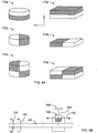
- Figure 4A depicts non-limiting examples of magnets that can be utilized in one or more embodiments of the rotational position sensor 100 as described herein.
- the magnet can be a cylindrical shaped magnet (172a, 172b, 172c) or some other shaped magnet such as a box shaped magnet (172d, 172e, 172f).
- the slanted line fill pattern and the unfilled pattern indicate two poles of a dipole magnet.
- the unfilled pattern can represent a north pole
- the slanted line fill pattern can represent a south pole.
- the magnet 106 can be a permanent magnet.
- the permanent magnet can be a single dipole magnet or a combination or two or more dipole magnets.
- a permanent magnet can include a magnet that includes a material that is magnetized and generates its own substantially persistent magnetic field.
- Such materials can include ferromagnetic materials such as iron, nickel, cobalt, and certain rare earth metals and some of their alloys.
- a single dipole magnet has what are generally referred to as “north” and “south” poles, such that magnetic field lines are designated as going from the north pole to the south pole.
- its magnetization axis is generally understood to be a line extending through the magnet's north and south poles.
- the example magnet 172a is a cylindrical shaped magnet having north and south poles along the cylinder's axis.
- the magnetization axis can be approximately coaxial with the cylindrical axis.
- a magnetization axis may or may not form relatively simple orientation with respect to the shape's axis.
- magnetization axis can include an overall characteristic of a magnet, as well as a local characteristic of a magnetic field pattern generated by a magnet.
- magnetization axis is depicted as being generally perpendicular to the longitudinal motion of the magnet. However, it will be understood that other orientations of the magnetization axis are also possible.
- magnet configurations 172b, 172c, 172e, and 172f can yield non-perpendicular magnetization axes when positioned as shown and moved along the indicated Y direction.
- the magnet 106 can be a dipole magnet positioned so that its magnetization axis 182 is substantially perpendicular to the direction of the magnet's longitudinal motion (depicted as arrow 174).
- a cylindrical permanent magnet can be positioned so that its north and south poles are generally form the magnetization axis 182 that is substantially perpendicular to the longitudinal direction.
- longitudinal motion can result from rotation (120, 130) of the shaft 102 to which the magnet 106 is coupled.
- such longitudinal motion can move the magnet 106 relative to the sensor element 108 so as to facilitate determination of the magnet's longitudinal position relative to the sensor element 108.
- the magnetization axis 182 can be generally similar to the axis of the magnet's shape (e.g., a cylinder).
- An example shown in Figure 4C depicts a more localized view of magnetic field lines 180 generated by the magnet 106.
- the magnet 106 depicted in Figures 4C to 7B are described in the context of a dipole magnet such as that shown in Figure 4B , it will be understood that a similar magnetic field pattern can be generated or approximated by other magnet configurations having one or more dipole magnets.
- the magnetization axis 182 depicted in Figure 4C can be representative of a local field affecting the sensor element 108.
- the magnet 106 can be oriented such that its magnetization axis 182 representative of magnetic field at or about the sensor element 108 is generally perpendicular to the translational motion direction. In certain embodiments, the magnet 106 can be positioned so that the magnetization axis and the longitudinal axis generally define a plane that extends through an approximate centre of the sensor element 108. In the context of the example coordinate system shown in Figure 2B , the magnetization axis of the magnet 106 is generally along the Z axis in such embodiments. As described herein, such a configuration can provide features that are desirable.
- Figure 4C shows a more detailed view of a pole section of the magnet 106 relative to a side view of the sensor element 108. As shown, the magnetization axis 182 of the magnet 106 is depicted as being generally perpendicular to a plane defined by the sensor element 108.
- depictions of magnetic field lines 180 generated by the magnet 106 Assuming that the shown pole is a magnetic north pole, several field vectors are depicted in their decomposed (BZ and BY) forms (in the example coordinate system shown in Figure 2B ). As shown, field vectors 184 are generally symmetrical about the magnetization axis 182. Thus, the Z component of the field vector 184a is generally same in direction and magnitude as the Z component of the field vector 184d; and the Y component of the vector 184a is opposite in direction but generally same in magnitude as the Y component of the vector 184d. Similarly, the field vector 184b is generally a mirror image of the field vector 184c.
- the BZ component alone is measured by the sensor element 108, then there may or may not be ambiguity in magnet's position determination.
- the measured BZ component may be that of the Y>0 portion of the curve 190. In such a situation, there is likely no ambiguity in position determination based on the BZ component alone.
- the sensor element 108 and the magnet 106 are configured so that the magnet's motion is allowed on both longitudinal sides of the sensor element, there can be an ambiguity in position determination that can be resolved.
- magnetic field component along the translational motion direction can be measured simultaneously with the BZ component.
- the magnet's position along the Y direction based on the values of BY component.
- utilizing the BZ component can be advantageous for a number of reasons. For example, detection of perpendicular component (relative to a magnetic field detection plane) is usually preferred over other components.
- the BY component has a value of zero or a value that is relatively small. Consequently, signal-to-noise ratio can be unacceptably low at what can be a mid-portion of the magnet's travel along the Y direction.
- the BZ component has a maximum value at generally the same mid-portion of the magnet's travel along the y direction. Further, the maximum value of the BZ component can be typically significantly higher than the maximum value of the BY component.
- Such features can include relative insensitivity of the output (170 in Figure 3 ) to various deviations in the magnet's orientation.
- Figures 6A and 6B show the magnet 106 mounted on the carrier 104, and viewed along the magnetization axis.
- mounting can be achieved by the carrier 104 defining a recess (262 in Figure 8 ) shaped similar to at least a portion of the magnet 106 (e.g., cylindrical shaped recess to receive cylindrical shaped magnet).
- Figures 6A and 6B show that due to the generally symmetric magnetic field, azimuthal orientation of the magnet 106 with respect to the magnetization axis (parallel to Z-axis in Figures 6A and 6B ) generally does not affect the magnetic field 180 reaching the sensor element (108 in Figure 4C ).
- an indicator 200 is depicted on the magnet 106.
- the magnet 106 is preferably mounted on the carrier 104 so that the magnet's magnetization axis is substantially along the Z-axis, and thus perpendicular to both X and Y axes. Due to various reasons, however, the magnetization axis may deviate from the Z-axis; and examples of such deviations are depicted in Figures 7A and 7B .
- a side view of the magnet-carrier assembly shows that the mounted magnet's axis 182 deviates from the Z-axis (indicated as 210) to result in the magnet 106 being tilted along the Y direction.
- an end view of the magnet-carrier assembly shows that the mounted magnet's axis 182 deviates from the Z-axis (indicated as 210) to result in the magnet 106 being tilted along the X direction.
- the magnet 106 can be tilted so as to yield a combination of X and Y tilts of Figures 7A and 7B .
- the magnetic field patterns may deviate from the ideal pattern depicted in Figures 5A and 5B .
- the BZ component is relatively large compared to the BY component, and because the deviation angle (relative to Z-axis) is relatively small, the net effect on BZ can be relatively small. Further, even if there are significant deviations in BZ and/or BY components, programmability in certain embodiments as described herein can account for such deviations and thus make the output even less sensitive to magnet orientation.
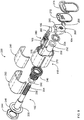
- Figures 8 to 10 show various views of an example configuration of the rotational position sensor 100.
- Figure 8 shows an exploded view 220;
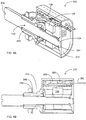
- Figure 9A shows an assembled cutaway perspective view 300;
- Figure 9B shows an assembled cutaway side view 310; and
- Figure 10 shows an assembled perspective view 320.
- the shaft 102 includes a first end 230 configured to facilitate transfer of torque to the shaft 102 from an external component (not shown).
- the first end 230 defines a slot 302 ( Figure 9A ) for such a purpose. It will be understood that a number of different configurations are possible.
- the shaft 102 also includes a second end 232 configured to couple with the carrier 104.
- the second end 232 of the shaft 102 and a matching aperture 260 of the carrier 104 define matching thread patterns that facilitate translational motion of the carrier 104 in response to rotation of the shaft 102.
- the second end 232 of the shaft 102 is shown to be dimensioned to receive a retaining clip 256 for limiting travel of the carrier 104.
- the second end 232 is also shown to include a tip 234 ( Figure 9A ) dimensioned to be received by a similarly dimensioned recess 304 defined by an end cap 272 so as to constrain the second end 232 of the shaft.
- a portion between the first and second ends (230, 232) of the shaft 102 is dimensioned to be supported within an aperture 252 defined by a sleeve 250.
- the sleeve 250 in turn is dimensioned to be secured to the housing 110 via a bushing 240 and a washer 254.
- supports of the shaft 102 by the sleeve 250 and the recess 304 of the end cap 274 allow the shaft to rotate with relative precision with respect to the housing 110.
- longitudinal motion of the shaft 102 with respect to the bushing 240 (and thus the housing 110) is inhibited by a retaining washer 242 and the washer 254.
- the bushing 240 can include external screw threads that mate with a mounting nut 244 to allow mounting of the sensor assembly. As shown in Figure 9B , the thread pattern on the bushing can be selected to provide an adjustable space 312 between the mounting nut 244 and the housing to facilitate mounting to various dimensioned structures such as plates. A washer 246 can further facilitate such mounting.
- a design may call for a rounded form of housing (when viewed longitudinally). More particularly, a design preference may call for a circular shaped housing with respect to the longitudinal axis of the shaft. However, if the interior of the housing is circularly shaped and the carrier is shaped circularly also with the shaft extending through the carrier's centre, the carrier's rotational tendency (in response to the shaft rotation) may not be inhibited in absence of some rotation-inhibiting features.
- a side wall 270 of the housing 110 can be shaped in a "U" shape (when viewed longitudinally), and the carrier can be shaped accordingly.
- the curved portion of the "U” can be substantially semi-circular in shape, and the longitudinal axis of the shaft 102 can be positioned at the centre of a circle that would be formed by two of such semicircles.
- the sides of the "U” can extend upward so as to inhibit the rotational tendency of the carrier 104.
- the top portion of the "U" shaped side wall 270 can be generally flat so as to accommodate a circuit assembly 280 that can be formed on a flat circuit board.
- the circuit assembly 280 can be formed as a substantially complete unit on a printed circuit board that is dimensioned to slide into grooves 276 formed near the top portion of the side wall 270.
- the example carrier 104 can also have a "U" shape to fit into the side wall 270 and slide longitudinally therein in response to the rotation of the shaft 102. Similar to the side wall 270, the top portion of the carrier 104 can be generally flat so as to accommodate the flat shaped circuit assembly 280. The height of the carrier's "U" shape can be selected so as to allow mounting of the magnet 106 thereon (via the recess 262) at a desired Z distance (see the example coordinate system in Figure 2B ) from the sensing element 108.
- the circuit assembly 280 can include one or more electrical contacts 282, and such contacts can be allowed to extend out of the housing 110 through appropriately formed holes on the end cap 272.
- a sealing member 274 can be provided so as to facilitate assembly of the rotational sensor device, as well as provide at least some sealing functionality for various components inside of the housing 110.
- Such sealing member can include a gasket, an epoxy, or some combination thereof.
- Figure 10 shows an assembled perspective view 320 of the rotational position sensor.
- the example configurations and arrangements of various components as described herein allow the rotational position sensor to provide magnetic field sensing functionality in a relatively simple and compact packaging while satisfying certain design criteria.
- the side wall 270 of the housing can include slots 324 dimensioned to facilitate easy mounting and removal of a shield 290.
- the rotational position sensor can be subjected to external electric and/or magnetic fields, and/or radiation.
- the shield 290 can be formed of material that has relatively high magnetic permeability.
- metal alloys such as Permalloys and Mu-metals can be used to form the shield 290.
- the shield 290 can be shaped to substantially conform to the upper portion 322 of the side wall 270.
- a cover 292 can be dimensioned to have its edges slide into the slots 324 and sandwich the shield 290 between the cover 292 and the upper portion 322 of the side wall 270.
- the cover 292 can be formed relatively easily from plastic to accommodate its shape that is more complex than the shield 290 (to fit into the slots 324).
- the rotational position sensor may be subjected to radiation such as X-ray, gamma radiation, energetic charged particles, neutrons, and/or other ionizing radiations.
- radiation such as X-ray, gamma radiation, energetic charged particles, neutrons, and/or other ionizing radiations.
- Such radiation can have detrimental effects on one or more parts of the rotational sensor, especially upon prolonged exposure.
- the sensor element 108 is formed from or based on semiconductor materials and/or components, exposure to radiation can degrade the sensing performance.
- Figure 11B shows that in certain embodiments, the example shield 290 can provide effective shielding of the sensor element 108 from radiation 328 without having to fully enclose the housing 270.
- the rotational position sensor can be oriented so that the shield 290 covers the sensor element 108 and/or other component(s) from the radiation so as to reduce their exposure.
- a rotational position sensor is being used to monitor the position of a movable patient platform for a radiation based treatment or imaging device.
- Many of such platforms are moved via jackscrews, and monitoring of the rotation of such jackscrews (by the rotational position sensor) can provide information about the platform position.
- direction and amount of radiation associated with the treatment or imaging device are generally well known.
- the rotational position sensor (with a shield) can be oriented so as to provide shielding effect from the radiation.
- the radiation shield 290 can be formed from and dimensioned to provide shielding effect from particular radiation by attenuating intensity of such radiation.
- Materials such as lead having heavy nuclei can be suitable for shielding X-ray and gamma radiation; whereas low density materials such as plastic or acrylic glass can be suitable for energetic electrons. Other materials for other types of radiations are also possible.
- the rotational position sensor can have a longer service life.
- the shield In the event that the shield needs to be replaced due to its own activated radiation from prolonged exposure, the shield can be replaced relatively easily; and the radioactive shield can be stored or disposed of safely easily due to its relatively small size and simple form.
- Figures 12A to 12F show various non-limiting examples of the housing 270 that can be used as part of the rotational position sensor. Also shown are non-limiting example configurations of the shield 290 having one or more features as described herein.
- FIG 12A shows an example housing configuration 500, where the housing 270 includes a curved wall 502, and first and second walls 504a, 504b that extend from the curved wall 502 so as to form a "U" shaped wall. Examples of advantageous features that can be provided by U-shaped walls are described herein in reference to Figures 8 and 9 .
- Figure 12A further shows that in certain embodiments, the carrier 104 can be shaped to generally conform to and move longitudinally relative to the interior of the U-shaped wall.
- the carrier 104 e.g., coupling with the shaft 102, and holding of the magnet 106 so as to allow longitudinal movement relative to the sensor element 108) are described herein.
- Figure 12B shows that in certain embodiments, the curved wall can be defined by a portion of a circle 516.
- the curved wall can be defined by a semi-circle 512 that is part of the shown circle 516.
- the portion of the circle defining the curved wall can be an arc that extends more or less than approximately 180 degrees associated with the semi-circle.
- the centre of the circle 516 that defines the semi-circle wall 512 can be substantially concentric with the centre of the shaft 102.
- first and second walls 514a, 514b can extend from the semi-circular wall 512 so as to form a U-shaped wall of the housing 270.
- the carrier 104 can be formed so as to substantially conform to the interior of the curved portion of the U-shaped wall.
- the curved portion of the carrier 104 can be defined by a semicircle that is part of the depicted circle 518 so as to conform to the example semi-circle wall 512.
- Figures 12C and 12E show that the top portion of the U-shaped housing can be configured in a number of different ways.
- An example configuration 520 of Figure 12C shows that a cap wall 524 can be coupled with the side walls (e.g., 514a, 514b in Figure 12B ) so as to form substantially square corners indicated as 522a and 522b.
- Another example configuration 540 of Figure 12E shows that a cap wall 544 can be coupled with the side walls (e.g., 514a, 514b in Figure 12B ) so as to form rounded corners indicated as 542a and 542b.
- Figures 12D and 12F show that the shield 290 having one or more functionalities as described herein can be shaped in a number of ways.
- An example configuration 530 of Figure 12D shows that the shield 290 can be shaped to generally conform to the example square-cornered (522a, 522b) top portion of the housing of Figure 12C , such that the shield 290 includes generally square corners indicated as 532a and 532b.
- Another example configuration 550 of Figure 12F shows that the shield 290 can be shaped to generally conform to the example rounded-cornered (542a, 542b) top portion of the housing of Figure 12E , such that the shield 290 includes rounded corners indicated as 552a and 552b.
- certain embodiments of the rotational position sensor 100 can include a programmable functionality with respect to, for example, calibration and operating dynamic range of the sensor 100.
- Figures 13 and 14 show examples of such programmability.
- a calibration system 330 can include a controller 332 in communication (depicted as line 334) with an actuator 336 so as to allow controlled rotation (arrow 338) of the shaft 102.
- the magnet 106 is depicted as moving relative to the sensor element 108 in a selected longitudinal motion range (depicted as 350) within the housing 110.
- an output signal can be collected through the contacts 282 via a connector 342, and such signal can be provided (line 340) to the controller 332 for processing.
- the calibration data 360 obtained in the foregoing manner can be represented in a number of ways. As shown in an example representation 360 in Figure 14 , a relationship between an output such as voltage and an input such as an angular position ⁇ can be obtained. For a plurality of calibration data points 362 obtained at a number of angular positions (e.g., obtained in increments of ⁇ ), a curve such as a linear line 380 can be fit to represent a relationship between the output voltage and the input angular position. Fitting of such representative curve can be achieved in a number of ways that are generally known.
- some portion(s) of the calibration data points may deviate systematically from a representative curve.
- data points near the upper limit of the angular position ⁇ are depicted as deviating from the linear line 380 (representative of the main portion of the angular range).
- Such deviation can occur due to a number of reasons.
- the systematic deviation is shown as being represented by a deviation curve 370.
- one or more corrections can be made so as to adjust an output so as to yield a desired output representation.
- the systematic deviation 370 can be adjusted (arrow 372) such that the output voltage can be represented as a substantially linear relationship within a defined range of the angular position ⁇ .
- information about the calibrated input-to-output relationship can be stored so as to be retrievable during operation of the rotational position sensor 100.
- information about the calibrated input-to-output relationship can be stored in the memory component 150 of Figure 3 in one of a number of formats, including, a lookup table, one or more parameters (e.g., slope and intercept parameters if linear relationship is used) for an algorithm representative of the relationship, etc.
- Figure 15 shows an example process 400 that can be implemented to achieve one or more features of the calibration process described in reference to Figures 13 and 14 .
- the shaft of the angular position sensor 100 can be rotated to a first position ( ⁇ 1 ) representative of a first limit (e.g., lower limit) of a desired range of rotational motion.
- the process 400 then can enter an iterative sequence where measurements are taken at incremental steps.
- the process 400 determines whether the current angular position ⁇ is less than a second position ( ⁇ 2 ) representative of a second limit (e.g., upper limit) of the desired range of rotational motion. If the answer is "Yes", the process 400 continues with another iteration of measurement.
- a calibration measurement can be obtained at the current shaft position ⁇ .
- the shaft position can be incrementally changed by ⁇ , and the process 400 can perform the test of the decision block 404 with the updated angular position.
- a systematic correction can optionally be applied in a process block 410.
- a representative output response e.g., a linear output response
- information about the representative output response can be stored so as to allow retrieval and use during operation of the angular position sensor 100.
- the calibration feature can include a locking feature to inhibit unauthorized calibration and/or altering of the information about the output response. In certain situations, such locking can occur after a calibration process performed at an authorized facility such as a fabrication facility.
- the calibration feature can further include a key (e.g., an electronic key) that allows an authorized party to unlock at least some of such functionalities. Locking, unlocking, and related operations for the foregoing can be achieved in known manners.
- the sensing element 108 can be an integrated circuit having capability to detect three components (BX, BY, BZ) of a magnetic field.
- IC integrated circuit
- Such an integrated circuit (IC) can include, for example, a Hall sensing monolithic sensor IC (model MLX90333) manufactured by Melexis Microelectronic Systems. Additional information about the example IC-based sensor element can be found in various documentations (including an application note) available at the manufacturer's website http://melexis.com.
- a combination of BZ and a longitudinal component can yield a quantity that has an approximately linear relationship with longitudinal position of the magnet (relative to the sensor element).
- ⁇ arctan(BY/BZ) ( ⁇ defined as shown in Figure 4C ) can yield an approximately linear response to longitudinal position of the magnet along the Y-axis.
- such an approximately linear relationship between the example quantity ⁇ and Y position can be extended to obtain an approximately linear relationship between the quantity ⁇ and angular position ( ⁇ ) of the shaft.
- Such extension of the relationship can be made readily, since the angular position ( ⁇ ) of the shaft generally has a linear relationship with translational motion of the magnet carrier coupled via substantially uniform threads.
- the example linear relationship between the angular position ( ⁇ ) of the shaft and the magnetic field quantity ⁇ can be provided with ah amplitude parameter that allows selection of a desired output range.
- the amplitude parameter can be selected so as to yield output values in a range between approximately 0 and 5 volts.
- an output of the rotational position sensor 100 does not even need to be a linear response to the input rotation.
- each angular position of the shaft has a unique corresponding output.
- an output of the rotational position sensor 100 is sometimes described as being a voltage. It will be understood, however, that the output can be in a number of different forms.
- the output can be in either digital or analogue format, and include but not limited to signals based on pulse width modulation or serial protocol.
- the output of the rotational position sensor 100 can be in a processed format.
- processing can include, for example, amplification and/or analogue-to-digital conversion.
- a sensor system 420 can include a position determination component 422 having features as described herein, and optionally a rate component 424.
- the rate component can be configured to determine an average or an approximation of instantaneous rotational speed of the shaft by combining the position measurements as described herein with time information (e.g., sampling period). In certain embodiments, such a rate determination can be extended to estimation of angular acceleration of the shaft.
- FIGs 17A and 17B schematically depict non-limiting examples of systems where the rotational position sensor can be used.
- a rotational position sensor 440 can be disposed between an actuator 432 and a controlled device 444 being mechanically driven by the actuator 432 via a mechanical coupling 436.
- mechanical output (arrow 434) of the actuator 432 can be coupled (arrow 438) to the sensor 440 (via, for example, the shaft), and that mechanical actuation can continue through the sensor 440 and be transmitted (arrow 442) to the controlled device 444.
- the sensor 440 can operate as described herein so as to facilitate determination of, for example, the rotational state of the mechanical coupling (e.g., rotational position of the shaft). As shown, the sensor 440 can be in communication with a controller 450 configured to control (line 452) the actuator 432 in response to the sensor's output. In certain embodiments, such sensing and controlling of the actuator 432 (and thus the controlled device 444) can be configured as a feedback control system.
- Figure 17B shows another example system 460 that can be a variation to the system of Figure 17A .
- a mechanical coupling component 466 can be configured to receive mechanical output (arrow 464) from an actuator 462 and provide separate mechanical outputs 472 and 468.
- the output 472 can be provided to a controlled device 474, and the output 468 can be provided to a sensor 470.
- the sensor 470 can provide an output 434 to a controller 480 configured to control (line 482) the actuator 462. Again, such sensing and controlling of the actuator 462 can be configured as a feedback control system.
- the example configuration 430 can be considered to be an inline type monitoring system, and the example configuration 460 can be considered to be a parallel type monitoring system. Other monitoring and/or feedback configurations are also possible.
- the functions, methods, algorithms, techniques, and components described herein may be implemented in hardware, software, firmware (e.g., including code segments), or any combination thereof. If implemented in software, the functions may be stored on or transmitted over as one or more instructions or code on a computer-readable medium. Tables, data structures, formulas, and so forth may be stored on a computer-readable medium.
- Computer-readable media include both computer storage media and communication media including any medium that facilitates transfer of a computer program from one place to another.
- a storage medium may be any available medium that can be accessed by a general purpose or special purpose computer.
- such computer-readable media can comprise RAM, ROM, EEPROM, CD-ROM or other optical disk storage, magnetic disk storage or other magnetic storage devices, or any other medium that can be used to carry or store desired program code means in the form of instructions or data structures and that can be accessed by a general-purpose or special-purpose computer, or a general-purpose or special-purpose processor. Also, any connection is properly termed a computer-readable medium.
- Disk and disc includes compact disc (CD), laser disc, optical disc, digital versatile disc (DVD), floppy disk and blu-ray disc where disks usually reproduce data magnetically, while discs reproduce data optically with lasers. Combinations of the above should also be included within the scope of computer-readable media.
- one or more processing units at a transmitter and/or a receiver may be implemented within one or more computing devices including, but not limited to, application specific integrated circuits (ASICs), digital signal processors (DSPs), digital signal processing devices (DSPDs), programmable logic devices (PLDs), field programmable gate arrays (FPGAs), processors, controllers, micro-controllers, microprocessors, electronic devices, other electronic units designed to perform the functions described herein, or a combination thereof.
- ASICs application specific integrated circuits
- DSPs digital signal processors
- DSPDs digital signal processing devices
- PLDs programmable logic devices
- FPGAs field programmable gate arrays
- processors controllers, micro-controllers, microprocessors, electronic devices, other electronic units designed to perform the functions described herein, or a combination thereof.
- the techniques described herein may be implemented with code segments (e.g., modules) that perform the functions described herein.
- the software codes may be stored in memory units and executed by processors.
- the memory unit may be implemented within the processor or external to the processor, in which case it can be communicatively coupled to the processor via various means as is known in the art.
- a code segment may represent a procedure, a function, a subprogram, a program, a routine, a subroutine, a module, a software package, a class, or any combination of instructions, data structures, or program statements.
- a code segment may be coupled to another code segment or a hardware circuit by passing and/or receiving information, data, arguments, parameters, or memory contents. Information, arguments, parameters, data, etc. may be passed, forwarded, or transmitted via any suitable means including memory sharing, message passing, token passing, network transmission, etc.
Landscapes
- Physics & Mathematics (AREA)
- General Physics & Mathematics (AREA)
- Transmission And Conversion Of Sensor Element Output (AREA)
Priority Applications (1)
| Application Number | Priority Date | Filing Date | Title |
|---|---|---|---|
| PL11250047T PL2365290T3 (pl) | 2010-01-18 | 2011-01-17 | Wieloobrotowy bezstykowy czujnik położenia o wysokiej rozdzielczości |
Applications Claiming Priority (1)
| Application Number | Priority Date | Filing Date | Title |
|---|---|---|---|
| US12/689,047 US8947076B2 (en) | 2010-01-18 | 2010-01-18 | High resolution non-contacting multi-turn position sensor |
Publications (3)
| Publication Number | Publication Date |
|---|---|
| EP2365290A2 EP2365290A2 (en) | 2011-09-14 |
| EP2365290A3 EP2365290A3 (en) | 2014-02-26 |
| EP2365290B1 true EP2365290B1 (en) | 2017-09-06 |
Family
ID=44118343
Family Applications (1)
| Application Number | Title | Priority Date | Filing Date |
|---|---|---|---|
| EP11250047.5A Active EP2365290B1 (en) | 2010-01-18 | 2011-01-17 | High resolution non-contacting multi-turn position sensor |
Country Status (6)
| Country | Link |
|---|---|
| US (2) | US8947076B2 (enExample) |
| EP (1) | EP2365290B1 (enExample) |
| JP (1) | JP5602032B2 (enExample) |
| CA (1) | CA2728306C (enExample) |
| HU (1) | HUE035502T2 (enExample) |
| PL (1) | PL2365290T3 (enExample) |
Families Citing this family (27)
| Publication number | Priority date | Publication date | Assignee | Title |
|---|---|---|---|---|
| US5879666A (en) * | 1996-10-24 | 1999-03-09 | The Procter & Gamble Company | Methods and compositions for reducing body odor |
| US8947076B2 (en) | 2010-01-18 | 2015-02-03 | Bourns, Inc. | High resolution non-contacting multi-turn position sensor |
| US9080895B2 (en) * | 2011-05-25 | 2015-07-14 | Sensata Technologies, Inc. | Magnetic position sensor assembly for measurement of rotational angular position of a rotating structure |
| US9593967B2 (en) * | 2011-07-17 | 2017-03-14 | Bourns, Inc. | High-resolution non-contacting multi-turn sensing systems and methods |
| JP6109834B2 (ja) * | 2011-10-07 | 2017-04-05 | ノボ・ノルデイスク・エー/エス | 3軸磁気センサに基づいて要素の位置を決定するシステム |
| CN102410849B (zh) * | 2011-11-23 | 2013-11-06 | 重庆诺柏恩自动化技术有限公司 | 一种可编程一体化传感器的控制方法 |
| US20130257419A1 (en) * | 2012-03-27 | 2013-10-03 | Be Aerospace, Inc. | Magnetic encoder system for aircraft seating actuator |
| US10376644B2 (en) | 2013-04-05 | 2019-08-13 | Novo Nordisk A/S | Dose logging device for a drug delivery device |
| WO2015038800A1 (en) * | 2013-09-11 | 2015-03-19 | Bourns, Inc. | Devices and methods related to high-resolution multi-turn sensors |
| DE102013225877A1 (de) * | 2013-12-13 | 2015-06-18 | Zf Friedrichshafen Ag | Verfahren und Vorrichtung zum Ermitteln eines Drehwinkels und/oder einer Drehzahl einer Motorwelle eines Motors |
| US9803731B2 (en) * | 2014-04-24 | 2017-10-31 | American Axle & Manufacturing, Inc. | Actuator device having cam and follower and controller configured to employ rate-based methodology to identify positioning of follower on cam at predetermined location |
| DE102014221988A1 (de) * | 2014-10-29 | 2016-05-04 | Zf Friedrichshafen Ag | Gebermagnet für einen Wegsensor, Wegsensor für ein Getriebe eines Fahrzeugs und Verfahren zum Herstellen eines Gebermagneten für einen Wegsensor |
| KR101952055B1 (ko) | 2014-12-29 | 2019-02-25 | 더 팀켄 컴퍼니 | 프로그램 가능 센서 |
| EP3247979A2 (en) * | 2015-01-23 | 2017-11-29 | Infineon Technologies AG | Out of shaft magnetic angle sensing system |
| US9739640B2 (en) | 2016-01-15 | 2017-08-22 | Infineon Technologies Ag | Rotation angle sensor system and method |
| AT519455B1 (de) * | 2016-10-27 | 2018-07-15 | Melecs Ews Gmbh | Sensoranordnung mit zumindest einem Magnetsensor |
| US10830571B2 (en) * | 2017-04-19 | 2020-11-10 | Analog Devices International Unlimited Company | Techniques for magnetic field direction based position sensor |
| US20190063951A1 (en) * | 2017-08-29 | 2019-02-28 | Littelfuse, Inc. | Sensitivity enhanced gear absolute position sensor |
| US10888382B2 (en) * | 2017-12-14 | 2021-01-12 | Acclarent, Inc. | Mounted patient tracking component for surgical navigation system |
| US11480488B2 (en) | 2018-09-28 | 2022-10-25 | Rosemount Inc. | Industrial process transmitter with radiation shield |
| JP2020187025A (ja) * | 2019-05-15 | 2020-11-19 | アイシン精機株式会社 | 回転角検出装置 |
| CN110487169B (zh) * | 2019-08-27 | 2024-05-14 | 成都宏明电子股份有限公司 | 用于多圈rs422通信协议输出的角位移磁敏传感器 |
| CN112815826B (zh) * | 2019-11-18 | 2024-09-03 | 芜湖美的厨卫电器制造有限公司 | 龙头开合角度的检测方法、装置、龙头和存储介质 |
| CN111561863B (zh) * | 2020-05-22 | 2022-04-15 | 维沃移动通信有限公司 | 一种电子设备 |
| US11519751B2 (en) | 2020-05-29 | 2022-12-06 | Analog Devices International Unlimited Company | Method of monitoring a magnetic sensor |
| US11422006B2 (en) * | 2020-06-18 | 2022-08-23 | Microsoft Technology Licensing, Llc | Device orientation sensor |
| US12235135B2 (en) * | 2021-04-12 | 2025-02-25 | Analog Devices International Unlimited Company | Magnetic sensor system with initialization mechanism |
Family Cites Families (79)
| Publication number | Priority date | Publication date | Assignee | Title |
|---|---|---|---|---|
| JPS4854957A (enExample) | 1971-11-08 | 1973-08-02 | ||
| US4037219A (en) | 1975-12-30 | 1977-07-19 | Westinghouse Electric Corporation | Meter dial encoder for remote meter reading |
| US4146174A (en) | 1977-06-08 | 1979-03-27 | R. D. Products, Inc. | Self clocking magnetic encoder |
| JPS6045804B2 (ja) | 1978-02-28 | 1985-10-12 | 日本電気株式会社 | 角度検出器 |
| JPS54118259A (en) | 1978-03-06 | 1979-09-13 | Nec Corp | Angle detector |
| US4293837A (en) | 1980-07-23 | 1981-10-06 | The Singer Company | Hall effect potentiometer |
| US4395695A (en) | 1980-07-25 | 1983-07-26 | Copal Company Limited | Non-contact magnetic potentiometer |
| CA1166713A (en) | 1980-10-15 | 1984-05-01 | Franc Gergek | Optical disc shaft encoder for machine control |
| US4445112A (en) | 1980-12-12 | 1984-04-24 | Bei Electronics, Inc. | Positional encoders with plug-together modules |
| JPS5886405A (ja) * | 1981-11-18 | 1983-05-24 | Nec Corp | 角度検出器 |
| US4475034A (en) | 1982-06-24 | 1984-10-02 | International Business Machines Corporation | Modular shaft encoder |
| US4670737A (en) | 1984-09-13 | 1987-06-02 | Sangamo Weston, Inc. | Method of initializing an optical encoder |
| US4588982A (en) | 1984-09-13 | 1986-05-13 | Sangamo Weston, Inc. | Optical shaft encoder |
| US4691101A (en) | 1985-06-19 | 1987-09-01 | Hewlett-Packard Company | Optical positional encoder comprising immediately adjacent detectors |
| US4712005A (en) | 1985-12-19 | 1987-12-08 | Kollmorgen Technologies Corporation | Floating mask encoder with assembly spacer |
| CA1270921A (en) | 1986-04-11 | 1990-06-26 | Donald E. Gray | Direction sensitive optical shaft encoder |
| CA1262269A (en) | 1986-11-21 | 1989-10-10 | Dennis J. Martell | Optical encoder with two photosensors |
| US4942394A (en) | 1987-12-21 | 1990-07-17 | Pitney Bowes Inc. | Hall effect encoder apparatus |
| US4928089A (en) | 1987-12-21 | 1990-05-22 | Pitney Bowes Inc. | Hall effect printwheel encoder |
| US4893121A (en) | 1987-12-21 | 1990-01-09 | Pitney Bowes Inc. | Printwheel and encoder assembly |
| US4841246A (en) | 1987-12-29 | 1989-06-20 | Eaton Corporation | Multiturn shaft position sensor having magnet movable with nonrotating linear moving nut |
| JP2736894B2 (ja) | 1988-05-27 | 1998-04-02 | 株式会社日立製作所 | 光ピックアップ並びにそれを備えた光ディスク装置及びロータリエンコーダ |
| US4893131A (en) | 1988-06-15 | 1990-01-09 | Smith William J | Mobile or ground mounted arcuate antenna |
| US4914389A (en) | 1988-10-24 | 1990-04-03 | Eaton Corporation | Multiturn shaft position sensor with backlash compensation |
| CA1305766C (en) | 1989-09-27 | 1992-07-28 | Timothy M. Malcolm | Encoder disc |
| US5789917A (en) | 1990-12-05 | 1998-08-04 | Moving Magnet Technologie Sa | Magnetic position sensor with hall probe formed in an air gap of a stator |
| US5444369A (en) | 1993-02-18 | 1995-08-22 | Kearney-National, Inc. | Magnetic rotational position sensor with improved output linearity |
| US5955881A (en) | 1994-10-18 | 1999-09-21 | Cts Corporation | Linkage position sensor having a magnet with two ramped sections for providing variable magnetic field |
| JP3382081B2 (ja) | 1995-06-01 | 2003-03-04 | 株式会社東芝 | レジストおよびこれを用いたパターン形成方法 |
| JP3139942B2 (ja) | 1995-06-27 | 2001-03-05 | 株式会社クボタ | ポリエチレンスリーブ工法における継手部施工方法 |
| JP3161290B2 (ja) | 1995-07-06 | 2001-04-25 | 三菱自動車エンジニアリング株式会社 | 中子造型装置 |
| JPH0925111A (ja) | 1995-07-10 | 1997-01-28 | Shin Etsu Chem Co Ltd | 低酸素けい素造粒物、その製造方法および窒化けい素の製造方法 |
| JPH0931290A (ja) | 1995-07-15 | 1997-02-04 | Mitsui Petrochem Ind Ltd | 防曇成形体 |
| JP3499330B2 (ja) | 1995-08-03 | 2004-02-23 | ヤマハマリン株式会社 | 4サイクル船外機の補機類配置構造 |
| US5893133A (en) | 1995-08-16 | 1999-04-06 | International Business Machines Corporation | Keyboard for a system and method for processing Chinese language text |
| JPH0953102A (ja) | 1995-08-17 | 1997-02-25 | Olympus Optical Co Ltd | 焼結体の製造方法 |
| JPH0958491A (ja) | 1995-08-19 | 1997-03-04 | Nissan Motor Co Ltd | 電動パワーステアリング装置 |
| JPH0963332A (ja) | 1995-08-21 | 1997-03-07 | Minebea Co Ltd | 面状光源装置 |
| JPH0963412A (ja) | 1995-08-23 | 1997-03-07 | Fujikura Ltd | メンブレンスイッチ |
| JPH0974628A (ja) | 1995-09-05 | 1997-03-18 | Meidensha Corp | 開閉装置 |
| JPH0979986A (ja) | 1995-09-13 | 1997-03-28 | Nippon Eranko Kk | 偏平物品の整列装置、偏平物品の搬送装置及びそれらを用いた偏平物品の外観検査装置 |
| JP2873439B2 (ja) | 1995-09-22 | 1999-03-24 | セイコープレシジョン株式会社 | プリント基板の穴明け装置及び穴明け方法 |
| JPH0992618A (ja) | 1995-09-25 | 1997-04-04 | Toshiba Corp | 多結晶シリコンの製造方法、薄膜トランジスタ、その製造方法および液晶表示装置 |
| JP3606654B2 (ja) | 1995-10-30 | 2005-01-05 | 富士通株式会社 | コンパイラ装置 |
| JPH09121958A (ja) | 1995-10-31 | 1997-05-13 | Matsushita Electric Works Ltd | キャビネット用椅子 |
| JPH09121907A (ja) | 1995-11-01 | 1997-05-13 | Sumiko Fukuoka | 靴 |
| JPH09139124A (ja) | 1995-11-14 | 1997-05-27 | Sumitomo Electric Ind Ltd | 複合多芯超電導線およびその製造方法 |
| JP3208057B2 (ja) | 1996-02-16 | 2001-09-10 | 住友特殊金属株式会社 | 耐食性永久磁石 |
| JP3597733B2 (ja) | 1999-08-09 | 2004-12-08 | アルプス電気株式会社 | 磁気式変位検出装置 |
| JP2001183166A (ja) | 1999-12-22 | 2001-07-06 | Next:Kk | 回転角検出装置および同装置を用いた回転角伝達装置 |
| WO2001061274A1 (en) | 2000-02-17 | 2001-08-23 | Control Products Inc. | Multi-turn, non-contacting rotary shaft position sensor |
| US7317313B2 (en) | 2002-11-14 | 2008-01-08 | Measurement Specialties, Inc. | Magnetic encoder apparatus |
| US7567284B2 (en) | 2003-06-17 | 2009-07-28 | Olympus Corporation | Encoder, lens-implement and digital camera |
| DE10334869B3 (de) | 2003-07-29 | 2004-09-16 | Tech3 E.K. | Drehwinkelsensor |
| DE112004002011B4 (de) | 2003-10-24 | 2011-06-22 | Kabushiki Kaisha Yaskawa Denki, Fukuoka | Magnetische Kodiereinrichtung und Stellglied |
| US7135857B2 (en) | 2003-12-12 | 2006-11-14 | Honeywell International, Inc. | Serially connected magnet and hall effect position sensor with air gaps between magnetic poles |
| EP3495782B1 (en) | 2004-01-22 | 2023-06-14 | Nsk Ltd. | Magnetic encoder and bearing |
| US7024946B2 (en) | 2004-01-23 | 2006-04-11 | Delphi Technologies, Inc. | Assembly for measuring movement of and a torque applied to a shaft |
| CN1997876A (zh) | 2004-06-16 | 2007-07-11 | 株式会社安川电机 | 磁性编码装置 |
| US7019517B2 (en) | 2004-07-20 | 2006-03-28 | Honeywell International Inc. | Offset magnet rotary position sensor |
| WO2006067878A1 (ja) | 2004-12-20 | 2006-06-29 | Harmonic Drive Systems Inc. | リング状マグネットの着磁方法および磁気エンコーダ |
| DE102005011099A1 (de) | 2005-03-10 | 2006-09-14 | Robert Bosch Gmbh | Verfahren und Vorrichtung zur berührungslosen Drehwinkelerfassung eines drehbaren Elements |
| JP4336984B2 (ja) | 2005-04-01 | 2009-09-30 | Nok株式会社 | 磁気式ロータリエンコーダのパルサーリング |
| JP2007113932A (ja) | 2005-10-18 | 2007-05-10 | Harmonic Drive Syst Ind Co Ltd | ギヤ付きモータの多回転絶対値エンコーダ |
| JP4780314B2 (ja) | 2006-03-31 | 2011-09-28 | Nok株式会社 | ロータリエンコーダ用パルサーリング |
| US7782047B2 (en) | 2006-04-21 | 2010-08-24 | Zf Friedrichshafen Ag | Dual axis magnetic field detector and magnets therefor |
| US7816881B2 (en) | 2006-06-29 | 2010-10-19 | Exlar Corporation | Method and apparatus for utilizing commutation sensors for speed and position control |
| KR101107904B1 (ko) | 2006-08-21 | 2012-01-25 | 지에스아이 그룹 코포레이션 | 회전식 광학적 위치 인코더, 서보 모터 어셈블리, 서보-제어 검류계 및 레이저 시스템 |
| US7443160B2 (en) | 2006-09-28 | 2008-10-28 | Wolf Ronald J | Position sensor |
| DE102006056609A1 (de) | 2006-11-30 | 2008-06-05 | Maxon Motor Ag | Kapazitiver Winkelkodierer und Feedereinschub für Bestückungsmaschinen von Leiterplatten |
| US7570047B2 (en) | 2007-06-18 | 2009-08-04 | Key Safety Systems, Inc. | Hall effect based angular position sensor |
| US8294457B2 (en) | 2007-09-07 | 2012-10-23 | Joral Llc | Rotary magnetic encoder assembly, chip and method |
| DE102007043221A1 (de) | 2007-09-11 | 2009-03-12 | Schaeffler Kg | Verfahren zum Herstellen eines Multipol-Encoders |
| US7557340B2 (en) | 2007-10-07 | 2009-07-07 | Avago Technologies Ecbu Ip (Singapore) Pte. Ltd. | Shaft-mounted detector for optical encoder having an aperture through the detector for receiving a rotary shaft of a motor |
| DE112008003309T5 (de) * | 2007-12-03 | 2010-10-07 | Cts Corp., Elkhart | Linearer Positionssensor |
| US20090152452A1 (en) | 2007-12-18 | 2009-06-18 | Avago Technologies Ecbu Ip (Singapore) Pte. Ltd. | Reflective multi-turn encoder |
| FR2925643B1 (fr) | 2007-12-21 | 2010-01-15 | Snr Roulements Sa | Dispositif d'etancheite a codeur magnetique integre comprenant au moins une levre en contact radial frottant |
| JP2011006897A (ja) | 2009-06-25 | 2011-01-13 | Jx Nippon Oil & Energy Corp | 水路設備用の複合構造物及びその製造方法 |
| US8947076B2 (en) | 2010-01-18 | 2015-02-03 | Bourns, Inc. | High resolution non-contacting multi-turn position sensor |
-
2010
- 2010-01-18 US US12/689,047 patent/US8947076B2/en active Active
-
2011
- 2011-01-17 EP EP11250047.5A patent/EP2365290B1/en active Active
- 2011-01-17 CA CA2728306A patent/CA2728306C/en active Active
- 2011-01-17 PL PL11250047T patent/PL2365290T3/pl unknown
- 2011-01-17 JP JP2011006897A patent/JP5602032B2/ja active Active
- 2011-01-17 HU HUE11250047A patent/HUE035502T2/en unknown
-
2015
- 2015-02-01 US US14/611,245 patent/US9518840B2/en active Active
Non-Patent Citations (1)
| Title |
|---|
| None * |
Also Published As
| Publication number | Publication date |
|---|---|
| PL2365290T3 (pl) | 2018-01-31 |
| EP2365290A3 (en) | 2014-02-26 |
| US20110175601A1 (en) | 2011-07-21 |
| HUE035502T2 (en) | 2018-05-02 |
| JP5602032B2 (ja) | 2014-10-08 |
| US20150300839A1 (en) | 2015-10-22 |
| US8947076B2 (en) | 2015-02-03 |
| EP2365290A2 (en) | 2011-09-14 |
| JP2011149939A (ja) | 2011-08-04 |
| CA2728306C (en) | 2018-05-01 |
| CA2728306A1 (en) | 2011-07-18 |
| US9518840B2 (en) | 2016-12-13 |
Similar Documents
| Publication | Publication Date | Title |
|---|---|---|
| EP2365290B1 (en) | High resolution non-contacting multi-turn position sensor | |
| EP2549237B1 (en) | High-resolution non-contacting multi-turn sensing systems and methods | |
| EP3543657B1 (en) | Sensor system comprising a multipole magnet | |
| JP6463789B2 (ja) | 磁気角度位置センサ | |
| Wu et al. | A rotary encoder with an eccentrically mounted ring magnet | |
| JP5893134B2 (ja) | 磁気式回転角検出器 | |
| US11300399B2 (en) | Device and method for determining the position of a permanent magnet | |
| KR20190045400A (ko) | 다극 자석을 사용하여 절대 각위치를 측정하기 위한 장치, 방법 및 센서 | |
| JP4769324B2 (ja) | 直線変位センサ | |
| JP2011149939A5 (enExample) | ||
| KR20130077872A (ko) | 마그네틱 다중-회전 절대 위치 추적 장치 | |
| KR20110090941A (ko) | 자기장 방향 측정장치 및 플럭스 컬렉터를 갖는 자기 위치 센서 | |
| CN103226000A (zh) | 磁场传感器 | |
| US20240393140A1 (en) | Position encoder based on halbach magnetic element | |
| Keller et al. | Technologies for precision magnetic field mapping | |
| US11636889B2 (en) | Automatic magnetic flow recording device | |
| JP4844917B2 (ja) | 角度検出装置の収装構造 | |
| RU2462724C2 (ru) | Бесконтактный датчик углового положения | |
| RU2312363C1 (ru) | Бесконтактный программируемый датчик абсолютного углового положения в 360° | |
| HK1208903B (en) | Arrangement, method and sensor for measuring an absolute angular position using a multi-pole magnet | |
| CN113670189A (zh) | 旋转角度感测装置 |
Legal Events
| Date | Code | Title | Description |
|---|---|---|---|
| PUAI | Public reference made under article 153(3) epc to a published international application that has entered the european phase |
Free format text: ORIGINAL CODE: 0009012 |
|
| AK | Designated contracting states |
Kind code of ref document: A2 Designated state(s): AL AT BE BG CH CY CZ DE DK EE ES FI FR GB GR HR HU IE IS IT LI LT LU LV MC MK MT NL NO PL PT RO RS SE SI SK SM TR |
|
| AX | Request for extension of the european patent |
Extension state: BA ME |
|
| PUAL | Search report despatched |
Free format text: ORIGINAL CODE: 0009013 |
|
| AK | Designated contracting states |
Kind code of ref document: A3 Designated state(s): AL AT BE BG CH CY CZ DE DK EE ES FI FR GB GR HR HU IE IS IT LI LT LU LV MC MK MT NL NO PL PT RO RS SE SI SK SM TR |
|
| AX | Request for extension of the european patent |
Extension state: BA ME |
|
| RIC1 | Information provided on ipc code assigned before grant |
Ipc: G01D 5/14 20060101AFI20140123BHEP |
|
| 17P | Request for examination filed |
Effective date: 20140826 |
|
| RBV | Designated contracting states (corrected) |
Designated state(s): AL AT BE BG CH CY CZ DE DK EE ES FI FR GB GR HR HU IE IS IT LI LT LU LV MC MK MT NL NO PL PT RO RS SE SI SK SM TR |
|
| 17Q | First examination report despatched |
Effective date: 20150702 |
|
| GRAP | Despatch of communication of intention to grant a patent |
Free format text: ORIGINAL CODE: EPIDOSNIGR1 |
|
| INTG | Intention to grant announced |
Effective date: 20170322 |
|
| GRAS | Grant fee paid |
Free format text: ORIGINAL CODE: EPIDOSNIGR3 |
|
| GRAA | (expected) grant |
Free format text: ORIGINAL CODE: 0009210 |
|
| AK | Designated contracting states |
Kind code of ref document: B1 Designated state(s): AL AT BE BG CH CY CZ DE DK EE ES FI FR GB GR HR HU IE IS IT LI LT LU LV MC MK MT NL NO PL PT RO RS SE SI SK SM TR |
|
| REG | Reference to a national code |
Ref country code: GB Ref legal event code: FG4D |
|
| REG | Reference to a national code |
Ref country code: CH Ref legal event code: EP Ref country code: AT Ref legal event code: REF Ref document number: 926365 Country of ref document: AT Kind code of ref document: T Effective date: 20170915 |
|
| REG | Reference to a national code |
Ref country code: IE Ref legal event code: FG4D |
|
| REG | Reference to a national code |
Ref country code: SE Ref legal event code: TRGR |
|
| REG | Reference to a national code |
Ref country code: DE Ref legal event code: R096 Ref document number: 602011041261 Country of ref document: DE |
|
| REG | Reference to a national code |
Ref country code: NL Ref legal event code: FP |
|
| REG | Reference to a national code |
Ref country code: FR Ref legal event code: PLFP Year of fee payment: 8 |
|
| REG | Reference to a national code |
Ref country code: LT Ref legal event code: MG4D |
|
| PG25 | Lapsed in a contracting state [announced via postgrant information from national office to epo] |
Ref country code: NO Free format text: LAPSE BECAUSE OF FAILURE TO SUBMIT A TRANSLATION OF THE DESCRIPTION OR TO PAY THE FEE WITHIN THE PRESCRIBED TIME-LIMIT Effective date: 20171206 Ref country code: LT Free format text: LAPSE BECAUSE OF FAILURE TO SUBMIT A TRANSLATION OF THE DESCRIPTION OR TO PAY THE FEE WITHIN THE PRESCRIBED TIME-LIMIT Effective date: 20170906 Ref country code: FI Free format text: LAPSE BECAUSE OF FAILURE TO SUBMIT A TRANSLATION OF THE DESCRIPTION OR TO PAY THE FEE WITHIN THE PRESCRIBED TIME-LIMIT Effective date: 20170906 Ref country code: HR Free format text: LAPSE BECAUSE OF FAILURE TO SUBMIT A TRANSLATION OF THE DESCRIPTION OR TO PAY THE FEE WITHIN THE PRESCRIBED TIME-LIMIT Effective date: 20170906 |
|
| PG25 | Lapsed in a contracting state [announced via postgrant information from national office to epo] |
Ref country code: ES Free format text: LAPSE BECAUSE OF FAILURE TO SUBMIT A TRANSLATION OF THE DESCRIPTION OR TO PAY THE FEE WITHIN THE PRESCRIBED TIME-LIMIT Effective date: 20170906 Ref country code: BG Free format text: LAPSE BECAUSE OF FAILURE TO SUBMIT A TRANSLATION OF THE DESCRIPTION OR TO PAY THE FEE WITHIN THE PRESCRIBED TIME-LIMIT Effective date: 20171206 Ref country code: RS Free format text: LAPSE BECAUSE OF FAILURE TO SUBMIT A TRANSLATION OF THE DESCRIPTION OR TO PAY THE FEE WITHIN THE PRESCRIBED TIME-LIMIT Effective date: 20170906 Ref country code: GR Free format text: LAPSE BECAUSE OF FAILURE TO SUBMIT A TRANSLATION OF THE DESCRIPTION OR TO PAY THE FEE WITHIN THE PRESCRIBED TIME-LIMIT Effective date: 20171207 Ref country code: LV Free format text: LAPSE BECAUSE OF FAILURE TO SUBMIT A TRANSLATION OF THE DESCRIPTION OR TO PAY THE FEE WITHIN THE PRESCRIBED TIME-LIMIT Effective date: 20170906 |
|
| PG25 | Lapsed in a contracting state [announced via postgrant information from national office to epo] |
Ref country code: CZ Free format text: LAPSE BECAUSE OF FAILURE TO SUBMIT A TRANSLATION OF THE DESCRIPTION OR TO PAY THE FEE WITHIN THE PRESCRIBED TIME-LIMIT Effective date: 20170906 Ref country code: RO Free format text: LAPSE BECAUSE OF FAILURE TO SUBMIT A TRANSLATION OF THE DESCRIPTION OR TO PAY THE FEE WITHIN THE PRESCRIBED TIME-LIMIT Effective date: 20170906 |
|
| REG | Reference to a national code |
Ref country code: HU Ref legal event code: AG4A Ref document number: E035502 Country of ref document: HU |
|
| PG25 | Lapsed in a contracting state [announced via postgrant information from national office to epo] |
Ref country code: SM Free format text: LAPSE BECAUSE OF FAILURE TO SUBMIT A TRANSLATION OF THE DESCRIPTION OR TO PAY THE FEE WITHIN THE PRESCRIBED TIME-LIMIT Effective date: 20170906 Ref country code: EE Free format text: LAPSE BECAUSE OF FAILURE TO SUBMIT A TRANSLATION OF THE DESCRIPTION OR TO PAY THE FEE WITHIN THE PRESCRIBED TIME-LIMIT Effective date: 20170906 Ref country code: IT Free format text: LAPSE BECAUSE OF FAILURE TO SUBMIT A TRANSLATION OF THE DESCRIPTION OR TO PAY THE FEE WITHIN THE PRESCRIBED TIME-LIMIT Effective date: 20170906 Ref country code: IS Free format text: LAPSE BECAUSE OF FAILURE TO SUBMIT A TRANSLATION OF THE DESCRIPTION OR TO PAY THE FEE WITHIN THE PRESCRIBED TIME-LIMIT Effective date: 20180106 Ref country code: SK Free format text: LAPSE BECAUSE OF FAILURE TO SUBMIT A TRANSLATION OF THE DESCRIPTION OR TO PAY THE FEE WITHIN THE PRESCRIBED TIME-LIMIT Effective date: 20170906 |
|
| REG | Reference to a national code |
Ref country code: DE Ref legal event code: R097 Ref document number: 602011041261 Country of ref document: DE |
|
| PLBE | No opposition filed within time limit |
Free format text: ORIGINAL CODE: 0009261 |
|
| STAA | Information on the status of an ep patent application or granted ep patent |
Free format text: STATUS: NO OPPOSITION FILED WITHIN TIME LIMIT |
|
| PG25 | Lapsed in a contracting state [announced via postgrant information from national office to epo] |
Ref country code: DK Free format text: LAPSE BECAUSE OF FAILURE TO SUBMIT A TRANSLATION OF THE DESCRIPTION OR TO PAY THE FEE WITHIN THE PRESCRIBED TIME-LIMIT Effective date: 20170906 |
|
| 26N | No opposition filed |
Effective date: 20180607 |
|
| PG25 | Lapsed in a contracting state [announced via postgrant information from national office to epo] |
Ref country code: SI Free format text: LAPSE BECAUSE OF FAILURE TO SUBMIT A TRANSLATION OF THE DESCRIPTION OR TO PAY THE FEE WITHIN THE PRESCRIBED TIME-LIMIT Effective date: 20170906 |
|
| REG | Reference to a national code |
Ref country code: CH Ref legal event code: PL |
|
| PG25 | Lapsed in a contracting state [announced via postgrant information from national office to epo] |
Ref country code: LU Free format text: LAPSE BECAUSE OF NON-PAYMENT OF DUE FEES Effective date: 20180117 |
|
| REG | Reference to a national code |
Ref country code: BE Ref legal event code: MM Effective date: 20180131 |
|
| PG25 | Lapsed in a contracting state [announced via postgrant information from national office to epo] |
Ref country code: BE Free format text: LAPSE BECAUSE OF NON-PAYMENT OF DUE FEES Effective date: 20180131 Ref country code: CH Free format text: LAPSE BECAUSE OF NON-PAYMENT OF DUE FEES Effective date: 20180131 Ref country code: LI Free format text: LAPSE BECAUSE OF NON-PAYMENT OF DUE FEES Effective date: 20180131 |
|
| PG25 | Lapsed in a contracting state [announced via postgrant information from national office to epo] |
Ref country code: MC Free format text: LAPSE BECAUSE OF FAILURE TO SUBMIT A TRANSLATION OF THE DESCRIPTION OR TO PAY THE FEE WITHIN THE PRESCRIBED TIME-LIMIT Effective date: 20170906 |
|
| PG25 | Lapsed in a contracting state [announced via postgrant information from national office to epo] |
Ref country code: MT Free format text: LAPSE BECAUSE OF NON-PAYMENT OF DUE FEES Effective date: 20180117 |
|
| PG25 | Lapsed in a contracting state [announced via postgrant information from national office to epo] |
Ref country code: TR Free format text: LAPSE BECAUSE OF FAILURE TO SUBMIT A TRANSLATION OF THE DESCRIPTION OR TO PAY THE FEE WITHIN THE PRESCRIBED TIME-LIMIT Effective date: 20170906 |
|
| PG25 | Lapsed in a contracting state [announced via postgrant information from national office to epo] |
Ref country code: PT Free format text: LAPSE BECAUSE OF FAILURE TO SUBMIT A TRANSLATION OF THE DESCRIPTION OR TO PAY THE FEE WITHIN THE PRESCRIBED TIME-LIMIT Effective date: 20170906 |
|
| PG25 | Lapsed in a contracting state [announced via postgrant information from national office to epo] |
Ref country code: MK Free format text: LAPSE BECAUSE OF NON-PAYMENT OF DUE FEES Effective date: 20170906 Ref country code: CY Free format text: LAPSE BECAUSE OF FAILURE TO SUBMIT A TRANSLATION OF THE DESCRIPTION OR TO PAY THE FEE WITHIN THE PRESCRIBED TIME-LIMIT Effective date: 20170906 |
|
| PG25 | Lapsed in a contracting state [announced via postgrant information from national office to epo] |
Ref country code: AL Free format text: LAPSE BECAUSE OF FAILURE TO SUBMIT A TRANSLATION OF THE DESCRIPTION OR TO PAY THE FEE WITHIN THE PRESCRIBED TIME-LIMIT Effective date: 20170906 |
|
| REG | Reference to a national code |
Ref country code: DE Ref legal event code: R082 Ref document number: 602011041261 Country of ref document: DE Representative=s name: VENNER SHIPLEY GERMANY LLP, DE Ref country code: DE Ref legal event code: R082 Ref document number: 602011041261 Country of ref document: DE Representative=s name: VENNER SHIPLEY LLP, DE |
|
| REG | Reference to a national code |
Ref country code: AT Ref legal event code: UEP Ref document number: 926365 Country of ref document: AT Kind code of ref document: T Effective date: 20170906 |
|
| P01 | Opt-out of the competence of the unified patent court (upc) registered |
Effective date: 20230515 |
|
| PGFP | Annual fee paid to national office [announced via postgrant information from national office to epo] |
Ref country code: PL Payment date: 20241104 Year of fee payment: 15 |
|
| PGFP | Annual fee paid to national office [announced via postgrant information from national office to epo] |
Ref country code: GB Payment date: 20241128 Year of fee payment: 15 |
|
| PGFP | Annual fee paid to national office [announced via postgrant information from national office to epo] |
Ref country code: FR Payment date: 20241111 Year of fee payment: 15 |
|
| PGFP | Annual fee paid to national office [announced via postgrant information from national office to epo] |
Ref country code: IE Payment date: 20241112 Year of fee payment: 15 |
|
| PGFP | Annual fee paid to national office [announced via postgrant information from national office to epo] |
Ref country code: SE Payment date: 20241114 Year of fee payment: 15 |
|
| PGFP | Annual fee paid to national office [announced via postgrant information from national office to epo] |
Ref country code: HU Payment date: 20241209 Year of fee payment: 15 |
|
| PGFP | Annual fee paid to national office [announced via postgrant information from national office to epo] |
Ref country code: DE Payment date: 20241120 Year of fee payment: 15 |
|
| PGFP | Annual fee paid to national office [announced via postgrant information from national office to epo] |
Ref country code: AT Payment date: 20241227 Year of fee payment: 15 |
|
| PGFP | Annual fee paid to national office [announced via postgrant information from national office to epo] |
Ref country code: NL Payment date: 20251112 Year of fee payment: 16 |