EP2352215A1 - Système de batterie secondaire - Google Patents
Système de batterie secondaire Download PDFInfo
- Publication number
- EP2352215A1 EP2352215A1 EP08878257A EP08878257A EP2352215A1 EP 2352215 A1 EP2352215 A1 EP 2352215A1 EP 08878257 A EP08878257 A EP 08878257A EP 08878257 A EP08878257 A EP 08878257A EP 2352215 A1 EP2352215 A1 EP 2352215A1
- Authority
- EP
- European Patent Office
- Prior art keywords
- power
- secondary battery
- secondary batteries
- stopped
- conversion means
- Prior art date
- Legal status (The legal status is an assumption and is not a legal conclusion. Google has not performed a legal analysis and makes no representation as to the accuracy of the status listed.)
- Withdrawn
Links
- 238000006243 chemical reaction Methods 0.000 claims description 20
- 238000001514 detection method Methods 0.000 claims description 8
- 238000010248 power generation Methods 0.000 claims description 7
- 238000000034 method Methods 0.000 claims description 5
- 101100508840 Daucus carota INV3 gene Proteins 0.000 abstract description 42
- 101150110971 CIN7 gene Proteins 0.000 abstract description 39
- 101150110298 INV1 gene Proteins 0.000 abstract description 39
- 101100397044 Xenopus laevis invs-a gene Proteins 0.000 abstract description 39
- 101100286980 Daucus carota INV2 gene Proteins 0.000 description 34
- 101100397045 Xenopus laevis invs-b gene Proteins 0.000 description 34
- 230000007704 transition Effects 0.000 description 24
- 239000000470 constituent Substances 0.000 description 5
- 238000010586 diagram Methods 0.000 description 4
- 238000012423 maintenance Methods 0.000 description 2
- BNOODXBBXFZASF-UHFFFAOYSA-N [Na].[S] Chemical compound [Na].[S] BNOODXBBXFZASF-UHFFFAOYSA-N 0.000 description 1
Images


Classifications
-
- H—ELECTRICITY
- H02—GENERATION; CONVERSION OR DISTRIBUTION OF ELECTRIC POWER
- H02J—CIRCUIT ARRANGEMENTS OR SYSTEMS FOR SUPPLYING OR DISTRIBUTING ELECTRIC POWER; SYSTEMS FOR STORING ELECTRIC ENERGY
- H02J3/00—Circuit arrangements for ac mains or ac distribution networks
- H02J3/28—Arrangements for balancing of the load in a network by storage of energy
- H02J3/32—Arrangements for balancing of the load in a network by storage of energy using batteries with converting means
-
- H—ELECTRICITY
- H02—GENERATION; CONVERSION OR DISTRIBUTION OF ELECTRIC POWER
- H02J—CIRCUIT ARRANGEMENTS OR SYSTEMS FOR SUPPLYING OR DISTRIBUTING ELECTRIC POWER; SYSTEMS FOR STORING ELECTRIC ENERGY
- H02J3/00—Circuit arrangements for ac mains or ac distribution networks
- H02J3/38—Arrangements for parallely feeding a single network by two or more generators, converters or transformers
-
- Y—GENERAL TAGGING OF NEW TECHNOLOGICAL DEVELOPMENTS; GENERAL TAGGING OF CROSS-SECTIONAL TECHNOLOGIES SPANNING OVER SEVERAL SECTIONS OF THE IPC; TECHNICAL SUBJECTS COVERED BY FORMER USPC CROSS-REFERENCE ART COLLECTIONS [XRACs] AND DIGESTS
- Y02—TECHNOLOGIES OR APPLICATIONS FOR MITIGATION OR ADAPTATION AGAINST CLIMATE CHANGE
- Y02E—REDUCTION OF GREENHOUSE GAS [GHG] EMISSIONS, RELATED TO ENERGY GENERATION, TRANSMISSION OR DISTRIBUTION
- Y02E60/00—Enabling technologies; Technologies with a potential or indirect contribution to GHG emissions mitigation
- Y02E60/10—Energy storage using batteries
Definitions
- the present invention relates to a secondary battery system using a secondary battery.
- the secondary battery system sometimes cannot efficiently be operated due to the residual power of the individual secondary batteries.
- An object of the invention is to provide a secondary battery system capable of efficiently operating a secondary battery system using a plurality of secondary batteries.
- a secondary battery system comprising: two or more secondary batteries; two or more power conversion means, which are provided respectively corresponding to the two or more secondary batteries, for converting electric power supplied respectively from corresponding one of the two or more secondary batteries; detection means for detecting that a residual stored power level of the secondary battery corresponding to one of the power conversion means operating becomes to be not greater than a predetermined rate of a residual stored power level of the secondary battery corresponding to stopped the power conversion means; and operation switch means for stopping operation of the power conversion means corresponding to the secondary battery whose residual stored power level is a target to be detected by the detection means, and starting operation of the stopped the power conversion means.
- FIG. 1 is a block diagram showing a configuration of a secondary battery system according to the first embodiment of the invention. Parts which are common to figures cited below are respectively denoted at common reference symbols. Reiterative detailed descriptions thereof will be omitted, and descriptions will be mainly made of different parts between the figures. Reiterative descriptions to later embodiments will be omitted as well.
- the secondary battery system includes secondary batteries B1, B2, and B3, power converters INV1, INV2, and INV3 connected respectively to secondary batteries B1, B2, and B3, transformers TR1, TR2, and TR3 connected respectively to the output sides of power converters INV1, INV2, and INV3, circuit breakers K1, K2, and K3 connected respectively to transformers TR1, TR2, and TR3, a circuit breaker KD connected so as to short-circuit the output sides of circuit breakers K1, K2, and K3 and provided between a connection point of the short-circuits and a load side supplied with electric power, and a control apparatus 1 which controls three power converters INV1, INV2, and INV3.
- Secondary batteries B1, B2, and B3 are, for example, sodium-sulfur batteries (NAS batteries). Secondary batteries B1, B2, and B3 supply charged electric power as direct current power to power converters INV1, INV2, and INV3 connected to the secondary batteries, respectively.
- NAS batteries sodium-sulfur batteries
- Power converters INV1, INV2, and INV3 respectively convert the direct current power supplied from secondary batteries B1, B2, and B3 into alternating current power, based on instructions from the control apparatus 1.
- Power converters INV1, INV2, and INV3 output the converted alternating current power to transformers TR1, TR2, and TR3 connected to the power converters, respectively.
- Transformer TR1 supplies the alternating current power from power converter INV1 to an electric power system on a load side sequentially through circuit breaker K1 and circuit breaker KD.
- Transformer TR2 supplies the alternating current power from power converter INV2 to the electric power system on the load side sequentially through circuit breaker K2 and circuit breaker KD.
- Transformer TR3 supplies the alternating current power from power converter INV3 to the electric power system on the load side sequentially through circuit breaker K3 and circuit breaker KD.
- Circuit breakers K1, K2, and K3 stop, by opening themselves, supply of the alternating current power output from power converters INV1, INV2, and INV3, respectively, to load side.
- Circuit breaker KD stops supply of electric power from the present secondary battery system by opening itself.
- the control apparatus 1 controls power converters INV1, INV2, and INV3.
- a setting value for switching operations of power converters INV1, INV2, and INV3 is set in the control apparatus 1.
- the control apparatus 1 switches operations of power converters INV1, INV2, and INV3.
- control of the control apparatus 1 will be described with reference to FIGS. 2A, 2B, 2C, 2D , 2E, 2F, and 2G .
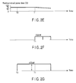
- FIGS. 2A, 2B, 2C, 2D , 2E, 2F, and 2G are graphs showing transitions of output power of power converters INV1, INV2, and INV3 and residual stored power levels of secondary batteries B1, B2, and B3 under control of the control apparatus 1 in the secondary battery system according to the first embodiment of the invention.
- FIG. 2A is a graph showing a transition of the residual stored power level of secondary battery B1.
- FIG. 2B is a graph showing a transition of the output power of power converter INV1.
- FIG. 2C is a graph showing a transition of the residual stored power level of secondary battery B2.
- FIG. 2D is a graph showing a transition of the output power of power converter INV2.
- FIG. 2E is a graph showing a transition of the residual stored power level of secondary battery B3.
- FIG. 2F is a graph showing a transition of the output power of power converter INV3.
- FIG. 2G is a graph showing a transition of output power of the secondary battery system.
- the secondary battery system is supposed to be required to supply electric power of 400 kW to the electric power system on the load side.
- Power converters INV1, INV2, and INV3 each are supposed to be capable of maximum power generation of 200 kW.
- a setting value of 70% is supposed to be set in the control apparatus 1 to switch power converters INV1, INV2, and INV3.
- the control apparatus 1 is supposed to start control at a time point T0.
- Power of 400 kW is required for the secondary battery system to supply to the electric power system on the load side.
- Each of power converters INV1, INV2, and INV3 is capable of maximum power generation of 200 kW. Power can be supplied by operating two power converters. Hence, the control apparatus 1 supplies power by two power converters, and stops the remaining one power converter.
- secondary batteries B1, B2, and B3 respectively have residual stored power levels as follows.
- the residual stored power level of secondary battery B1 is 90%.
- the residual stored power level of secondary battery B2 is 100%.
- the residual stored power level of secondary battery B1 is 70%.
- control apparatus 1 operates power converters INV1, INV2, and INV3 connected to the two secondary batteries B1 and B2 in order from the greatest residual stored power level.
- the control apparatus 1 stops power converter INV3 connected to secondary battery B3 having the smallest residual stored power level.
- the control apparatus 1 operates power converters INV1 and INV2 from time point T0 to a time point T1.
- the residual stored power level of power converter INV1 reaches approximately 49%.
- the 49% is an equivalent value to 70% as the setting value which is set in the control apparatus 1 for the residual stored power level of the stopped power converter INV3.
- control apparatus 1 stops power converter INV1, and operates power converter INV3.
- A% is a residual stored power level of a stopped power converter
- B% is a setting value in the control apparatus 1
- C% is a residual stored power level of one of operating power converters which has the smallest residual stored power level.
- control apparatus 1 stops operating one power converter having the smallest residual stored power level, and starts operating a stopped power converter.
- the control apparatus 1 stops operating power converter INV1, and starts operating power converter INV3.
- the control apparatus 1 operates power converters INV1, INV2, and INV3 by repeating an operation process as described above.
- the secondary battery system can supply electric power to the electric power system on the load side by operating the power converters so as to equalize residual stored power levels of all secondary batteries B1, B2, and B3. By maintaining the residual stored power levels to be uniform in this manner, operation and maintenance of the equipment in the secondary battery system can be facilitated.
- FIG. 3 is a block diagram showing a configuration of a secondary battery system according to the second embodiment of the invention.
- control apparatus 1 in the secondary battery system according to the first embodiment shown in FIG. 1 is substituted with a control apparatus 1A.
- the other features are configured in the same manner as in the secondary battery system according to the first embodiment.
- the control apparatus 1A controls power converters INV1, INV2, and INV3.
- a setting value for switching operations of power converters INV1, INV2, and INV3 is set in the control apparatus 1A. Based on the setting value, the control apparatus 1A switches power converters INV1, INV2, and INV3.
- control of the control apparatus 1A will be described with reference to FIGS. 4A, 4B, 4C, and 4D .
- FIGS. 4A, 4B, 4C, and 4D are graphs showing transitions of output power of power converters INV1, INV2, and INV3 under control of the control apparatus 1A in the secondary battery system according to the second embodiment of the invention.
- FIG. 4A is a graph showing a transition of the output power of power converter INV1.
- FIG. 4B is a graph showing a transition of the output power of power converter INV2.
- FIG. 4C is a graph showing a transition of the output power of power converter INV3.
- FIG. 4D is a graph showing a transition of output power of the secondary battery system.
- the secondary battery system is now supposed to be required to supply electric power of 400 kW to the electric power system on the load side.
- Power converters INV1, INV2, and INV3 each are supposed to be capable of maximum power generation of 200 kW.
- Residual stored power levels of secondary batteries B1, B2, and B3 corresponding respectively to power converters INV1, INV2, and INV3 are supposed to be substantially uniform.
- a setting value which is set in the control apparatus 1A to switch operations of power converters INV1, INV2, and INV3 is supposed to be a time period T.
- the control apparatus 1A is supposed to start control at a time point T0.
- Power of 400 kW is required for the secondary battery system to supply to the electric power system on the load side.
- Each of power converters INV1, INV2, and INV3 is capable of maximum power generation of 200 kW. Power can be supplied by operating two power converters. Hence, the control apparatus 1A supplies power by two power converters, and stops the remaining one power converter.
- the control apparatus 1A starts operation of the two power converters INV1 and INV3.
- the control apparatus 1A stops operating power converter INV3, and starts operating power converter INV2. In this manner, the control apparatus 1A switches one power converter to operate, from power converter INV3 to power converter INV2.
- the control apparatus 1A stops operating power converter INV1, and starts operating power converter INV3. In this manner, the control apparatus 1A switches a power converter to operate, from power converter INV1 to power converter INV3.
- the control apparatus 1A switches a power converter to operate among power converters INV1, INV2, and INV3.
- the control apparatus 1A operates power converters INV1, INV2, and INV3 by repeating such switching.
- power converters INV1, INV2, and INV3 each repeat a stop after continuous operation for time period T as the setting value.
- each of the embodiments employs three secondary batteries and three power converters
- any number of secondary batteries as well as power converters can be employed insofar as the number is not smaller than two.
- one power converter is stopped, two or more power converters may be stopped insofar as the electric power system on the load side can be supplied with a required power. In such a configuration, if two or more power converters stop operating and if a power converter whose operation is to be started is selected, a power converter corresponding to a secondary battery having the greatest residual stored power level may be selected. In this manner, residual stored power levels of all the secondary batteries can be consumed uniformly.
- NAS batteries as the secondary batteries
- other types of batteries may be employed.
- a secondary battery system capable of efficiently operating a secondary battery system using a plurality of secondary batteries.
Landscapes
- Engineering & Computer Science (AREA)
- Power Engineering (AREA)
- Charge And Discharge Circuits For Batteries Or The Like (AREA)
- Supply And Distribution Of Alternating Current (AREA)
- Secondary Cells (AREA)
Applications Claiming Priority (1)
| Application Number | Priority Date | Filing Date | Title |
|---|---|---|---|
| PCT/JP2008/071040 WO2010058460A1 (fr) | 2008-11-19 | 2008-11-19 | Système de batterie secondaire |
Publications (2)
| Publication Number | Publication Date |
|---|---|
| EP2352215A1 true EP2352215A1 (fr) | 2011-08-03 |
| EP2352215A4 EP2352215A4 (fr) | 2014-01-15 |
Family
ID=42197907
Family Applications (1)
| Application Number | Title | Priority Date | Filing Date |
|---|---|---|---|
| EP08878257.8A Withdrawn EP2352215A4 (fr) | 2008-11-19 | 2008-11-19 | Système de batterie secondaire |
Country Status (9)
| Country | Link |
|---|---|
| US (1) | US9214814B2 (fr) |
| EP (1) | EP2352215A4 (fr) |
| JP (1) | JP5501248B2 (fr) |
| KR (1) | KR101493124B1 (fr) |
| CN (1) | CN102217162B (fr) |
| AU (1) | AU2008364377B2 (fr) |
| CA (1) | CA2743994C (fr) |
| MY (1) | MY160070A (fr) |
| WO (1) | WO2010058460A1 (fr) |
Cited By (1)
| Publication number | Priority date | Publication date | Assignee | Title |
|---|---|---|---|---|
| EP2698897A4 (fr) * | 2011-04-11 | 2015-06-10 | Ngk Insulators Ltd | Dispositif de stockage d'énergie et procédé de commande de fonctionnement de dispositif de stockage d'énergie |
Families Citing this family (8)
| Publication number | Priority date | Publication date | Assignee | Title |
|---|---|---|---|---|
| CN102457072A (zh) * | 2010-10-22 | 2012-05-16 | 湖州雷霆能源科技有限公司 | 光电互补电池的充放电方法及系统 |
| CN102122826A (zh) * | 2011-01-17 | 2011-07-13 | 中国南方电网有限责任公司电网技术研究中心 | 一种大容量蓄电池储能双向换流器 |
| JP5732134B2 (ja) * | 2011-06-09 | 2015-06-10 | 東芝三菱電機産業システム株式会社 | 無停電電源システム |
| JP5849518B2 (ja) * | 2011-08-12 | 2016-01-27 | 株式会社Ihi | 電源システム |
| CN102355040A (zh) * | 2011-10-19 | 2012-02-15 | 北京四方继保自动化股份有限公司 | 与电池成组应用相匹配的变流器模块化设计与控制方法 |
| JP5851879B2 (ja) * | 2012-02-21 | 2016-02-03 | 三菱重工業株式会社 | 電力制御装置 |
| JP6323822B1 (ja) * | 2017-07-07 | 2018-05-16 | Mirai−Labo株式会社 | 電源装置および電源制御方法 |
| EP3462560B1 (fr) * | 2017-09-27 | 2021-05-12 | Indielux UG (Haftungsbeschränkt) | Procédé et système permettant de déterminer et de réguler une alimentation d'électricité à un réseau électrique à partir d'un côté de charge d'un circuit électrique |
Citations (2)
| Publication number | Priority date | Publication date | Assignee | Title |
|---|---|---|---|---|
| JPH0946914A (ja) * | 1995-07-31 | 1997-02-14 | Oki Electric Ind Co Ltd | 電源供給装置及びその充電装置 |
| EP1517021A1 (fr) * | 2002-06-26 | 2005-03-23 | JFE Steel Corporation | Procede d'elimination des fluctuations d'energie et installation de production d'energie utilisant ce procede |
Family Cites Families (21)
| Publication number | Priority date | Publication date | Assignee | Title |
|---|---|---|---|---|
| JP3599387B2 (ja) * | 1994-11-07 | 2004-12-08 | 東京電力株式会社 | 電力貯蔵システム |
| CN1044954C (zh) * | 1995-02-20 | 1999-09-01 | 三洋电机株式会社 | 向电子器具供电的电源装置 |
| JPH11252812A (ja) * | 1998-02-27 | 1999-09-17 | Nec Yonezawa Ltd | バッテリ放電制御方法および装置 |
| JP2000116014A (ja) * | 1998-10-06 | 2000-04-21 | Hitachi Ltd | 電力貯蔵装置 |
| US6111764A (en) * | 1998-10-12 | 2000-08-29 | Sanyo Denki Co., Ltd. | Power failure-free power supply apparatus |
| JP3697121B2 (ja) * | 1998-10-15 | 2005-09-21 | キヤノン株式会社 | 太陽光発電装置およびその制御方法 |
| JP2001103740A (ja) * | 1999-09-30 | 2001-04-13 | Oki Electric Ind Co Ltd | 電源回路 |
| JP3398703B2 (ja) * | 2000-02-14 | 2003-04-21 | 米沢日本電気株式会社 | 放電回路及びデューティー比設定方法 |
| JP2001327083A (ja) * | 2000-05-18 | 2001-11-22 | Ngk Insulators Ltd | 高温二次電池による電力貯蔵及び補償システム |
| JP3854175B2 (ja) * | 2002-03-01 | 2006-12-06 | インターナショナル・ビジネス・マシーンズ・コーポレーション | 電気機器、コンピュータ装置、コントローラ、電池切換方法、およびプログラム |
| US7081737B2 (en) * | 2003-06-19 | 2006-07-25 | O2Micro International Limited | Battery cell monitoring and balancing circuit |
| CN1300910C (zh) * | 2003-07-23 | 2007-02-14 | 黄府能 | 一种电池供电装置 |
| JP5039980B2 (ja) | 2005-11-14 | 2012-10-03 | 日立ビークルエナジー株式会社 | 二次電池モジュール |
| JP4784566B2 (ja) * | 2006-07-12 | 2011-10-05 | 日産自動車株式会社 | 二次電池の入出力電力制御装置及び入出力電力制御方法 |
| JP4886562B2 (ja) * | 2007-03-19 | 2012-02-29 | 本田技研工業株式会社 | 電力変換器及び多入出力電力変換器 |
| CN101436830B (zh) * | 2007-11-15 | 2011-06-08 | 鸿富锦精密工业(深圳)有限公司 | 电源装置及其保护方法 |
| US8648568B2 (en) * | 2008-01-17 | 2014-02-11 | Hewlett-Packard Development Company, L.P. | Backup power system management |
| JP4530078B2 (ja) * | 2008-06-04 | 2010-08-25 | トヨタ自動車株式会社 | 蓄電制御装置及び車両 |
| CN102202929B (zh) * | 2008-10-31 | 2014-01-01 | 丰田自动车株式会社 | 电动车辆的电源系统及其控制方法 |
| EP2371610A4 (fr) * | 2008-11-28 | 2014-09-10 | Toyota Motor Co Ltd | Système de charge de véhicule |
| JP4985873B2 (ja) * | 2009-04-23 | 2012-07-25 | トヨタ自動車株式会社 | 電動車両の電源システムおよびその制御方法 |
-
2008
- 2008-11-19 CA CA2743994A patent/CA2743994C/fr active Active
- 2008-11-19 EP EP08878257.8A patent/EP2352215A4/fr not_active Withdrawn
- 2008-11-19 WO PCT/JP2008/071040 patent/WO2010058460A1/fr active Application Filing
- 2008-11-19 CN CN200880132071.XA patent/CN102217162B/zh active Active
- 2008-11-19 MY MYPI2011002231A patent/MY160070A/en unknown
- 2008-11-19 JP JP2010539071A patent/JP5501248B2/ja active Active
- 2008-11-19 AU AU2008364377A patent/AU2008364377B2/en active Active
- 2008-11-19 KR KR1020117011428A patent/KR101493124B1/ko active IP Right Grant
-
2011
- 2011-05-17 US US13/109,766 patent/US9214814B2/en active Active
Patent Citations (2)
| Publication number | Priority date | Publication date | Assignee | Title |
|---|---|---|---|---|
| JPH0946914A (ja) * | 1995-07-31 | 1997-02-14 | Oki Electric Ind Co Ltd | 電源供給装置及びその充電装置 |
| EP1517021A1 (fr) * | 2002-06-26 | 2005-03-23 | JFE Steel Corporation | Procede d'elimination des fluctuations d'energie et installation de production d'energie utilisant ce procede |
Non-Patent Citations (1)
| Title |
|---|
| See also references of WO2010058460A1 * |
Cited By (1)
| Publication number | Priority date | Publication date | Assignee | Title |
|---|---|---|---|---|
| EP2698897A4 (fr) * | 2011-04-11 | 2015-06-10 | Ngk Insulators Ltd | Dispositif de stockage d'énergie et procédé de commande de fonctionnement de dispositif de stockage d'énergie |
Also Published As
| Publication number | Publication date |
|---|---|
| EP2352215A4 (fr) | 2014-01-15 |
| CN102217162A (zh) | 2011-10-12 |
| WO2010058460A1 (fr) | 2010-05-27 |
| AU2008364377A1 (en) | 2010-05-27 |
| CN102217162B (zh) | 2014-05-21 |
| KR101493124B1 (ko) | 2015-02-12 |
| JP5501248B2 (ja) | 2014-05-21 |
| US20110278930A1 (en) | 2011-11-17 |
| CA2743994C (fr) | 2018-02-20 |
| US9214814B2 (en) | 2015-12-15 |
| KR20110096117A (ko) | 2011-08-29 |
| CA2743994A1 (fr) | 2010-05-27 |
| MY160070A (en) | 2017-02-15 |
| JPWO2010058460A1 (ja) | 2012-04-12 |
| AU2008364377B2 (en) | 2015-07-16 |
Similar Documents
| Publication | Publication Date | Title |
|---|---|---|
| EP2352215A1 (fr) | Système de batterie secondaire | |
| CN106464006B (zh) | 不间断供电电源装置 | |
| EP2991183B1 (fr) | Système et procédé de charge et de décharge et système de génération d'énergie photovoltaïque | |
| US20160218558A1 (en) | Power Supply Bus Circuit | |
| US10833528B2 (en) | Uninterruptible power supply system | |
| KR102119330B1 (ko) | 배터리 동작식 계전기 시험 장치 2 | |
| JP6468593B2 (ja) | 蓄電システム | |
| KR102178447B1 (ko) | 무정전 전력 공급 마이크로그리드 시스템 | |
| US10186390B2 (en) | Relay circuit for contact preservation and method for controlling relay circuit | |
| US9929673B2 (en) | Method for feeding energy from photovoltaic modules of a photovoltaic system and inverter designed for executing this method | |
| JP6199804B2 (ja) | 電力制御システム、電力制御システムの制御方法、及び電力制御装置 | |
| US20150214743A1 (en) | Safe electrical power-supply system | |
| CA3004928C (fr) | Appareil d'essai a relais alimente par accumulateur | |
| JP2008029044A (ja) | 直流多端子配電システムとその運転方法 | |
| EP3047704B1 (fr) | Onduleur entre un panneau solaire, une source et la charge | |
| RU2658307C1 (ru) | Электромеханическое устройство | |
| JP7233279B2 (ja) | 系統連系装置 | |
| WO2022244643A1 (fr) | Dispositif d'alimentation électrique | |
| JP5771116B2 (ja) | 無停電電源装置 | |
| JP2012231641A (ja) | 電圧変換装置 | |
| JP6199794B2 (ja) | 電力制御システム、電力制御システムの制御方法、及び電力制御装置 | |
| CN118117652A (zh) | 一种供电系统和供电方法 |
Legal Events
| Date | Code | Title | Description |
|---|---|---|---|
| PUAI | Public reference made under article 153(3) epc to a published international application that has entered the european phase |
Free format text: ORIGINAL CODE: 0009012 |
|
| 17P | Request for examination filed |
Effective date: 20110519 |
|
| AK | Designated contracting states |
Kind code of ref document: A1 Designated state(s): AT BE BG CH CY CZ DE DK EE ES FI FR GB GR HR HU IE IS IT LI LT LU LV MC MT NL NO PL PT RO SE SI SK TR |
|
| DAX | Request for extension of the european patent (deleted) | ||
| A4 | Supplementary search report drawn up and despatched |
Effective date: 20131216 |
|
| RIC1 | Information provided on ipc code assigned before grant |
Ipc: H02J 3/32 20060101ALI20131210BHEP Ipc: H02J 3/38 20060101AFI20131210BHEP |
|
| 17Q | First examination report despatched |
Effective date: 20170306 |
|
| GRAP | Despatch of communication of intention to grant a patent |
Free format text: ORIGINAL CODE: EPIDOSNIGR1 |
|
| INTG | Intention to grant announced |
Effective date: 20190214 |
|
| STAA | Information on the status of an ep patent application or granted ep patent |
Free format text: STATUS: THE APPLICATION IS DEEMED TO BE WITHDRAWN |
|
| 18D | Application deemed to be withdrawn |
Effective date: 20190625 |