EP2345552B1 - Véhicule électrique - Google Patents
Véhicule électrique Download PDFInfo
- Publication number
- EP2345552B1 EP2345552B1 EP08877268.6A EP08877268A EP2345552B1 EP 2345552 B1 EP2345552 B1 EP 2345552B1 EP 08877268 A EP08877268 A EP 08877268A EP 2345552 B1 EP2345552 B1 EP 2345552B1
- Authority
- EP
- European Patent Office
- Prior art keywords
- power
- storage chamber
- reception unit
- door
- power reception
- Prior art date
- Legal status (The legal status is an assumption and is not a legal conclusion. Google has not performed a legal analysis and makes no representation as to the accuracy of the status listed.)
- Active
Links
Images


Classifications
-
- B—PERFORMING OPERATIONS; TRANSPORTING
- B60—VEHICLES IN GENERAL
- B60L—PROPULSION OF ELECTRICALLY-PROPELLED VEHICLES; SUPPLYING ELECTRIC POWER FOR AUXILIARY EQUIPMENT OF ELECTRICALLY-PROPELLED VEHICLES; ELECTRODYNAMIC BRAKE SYSTEMS FOR VEHICLES IN GENERAL; MAGNETIC SUSPENSION OR LEVITATION FOR VEHICLES; MONITORING OPERATING VARIABLES OF ELECTRICALLY-PROPELLED VEHICLES; ELECTRIC SAFETY DEVICES FOR ELECTRICALLY-PROPELLED VEHICLES
- B60L5/00—Current collectors for power supply lines of electrically-propelled vehicles
- B60L5/005—Current collectors for power supply lines of electrically-propelled vehicles without mechanical contact between the collector and the power supply line
-
- B—PERFORMING OPERATIONS; TRANSPORTING
- B60—VEHICLES IN GENERAL
- B60L—PROPULSION OF ELECTRICALLY-PROPELLED VEHICLES; SUPPLYING ELECTRIC POWER FOR AUXILIARY EQUIPMENT OF ELECTRICALLY-PROPELLED VEHICLES; ELECTRODYNAMIC BRAKE SYSTEMS FOR VEHICLES IN GENERAL; MAGNETIC SUSPENSION OR LEVITATION FOR VEHICLES; MONITORING OPERATING VARIABLES OF ELECTRICALLY-PROPELLED VEHICLES; ELECTRIC SAFETY DEVICES FOR ELECTRICALLY-PROPELLED VEHICLES
- B60L50/00—Electric propulsion with power supplied within the vehicle
- B60L50/10—Electric propulsion with power supplied within the vehicle using propulsion power supplied by engine-driven generators, e.g. generators driven by combustion engines
- B60L50/16—Electric propulsion with power supplied within the vehicle using propulsion power supplied by engine-driven generators, e.g. generators driven by combustion engines with provision for separate direct mechanical propulsion
-
- B—PERFORMING OPERATIONS; TRANSPORTING
- B60—VEHICLES IN GENERAL
- B60L—PROPULSION OF ELECTRICALLY-PROPELLED VEHICLES; SUPPLYING ELECTRIC POWER FOR AUXILIARY EQUIPMENT OF ELECTRICALLY-PROPELLED VEHICLES; ELECTRODYNAMIC BRAKE SYSTEMS FOR VEHICLES IN GENERAL; MAGNETIC SUSPENSION OR LEVITATION FOR VEHICLES; MONITORING OPERATING VARIABLES OF ELECTRICALLY-PROPELLED VEHICLES; ELECTRIC SAFETY DEVICES FOR ELECTRICALLY-PROPELLED VEHICLES
- B60L50/00—Electric propulsion with power supplied within the vehicle
- B60L50/50—Electric propulsion with power supplied within the vehicle using propulsion power supplied by batteries or fuel cells
- B60L50/60—Electric propulsion with power supplied within the vehicle using propulsion power supplied by batteries or fuel cells using power supplied by batteries
- B60L50/61—Electric propulsion with power supplied within the vehicle using propulsion power supplied by batteries or fuel cells using power supplied by batteries by batteries charged by engine-driven generators, e.g. series hybrid electric vehicles
- B60L50/62—Electric propulsion with power supplied within the vehicle using propulsion power supplied by batteries or fuel cells using power supplied by batteries by batteries charged by engine-driven generators, e.g. series hybrid electric vehicles charged by low-power generators primarily intended to support the batteries, e.g. range extenders
-
- B—PERFORMING OPERATIONS; TRANSPORTING
- B60—VEHICLES IN GENERAL
- B60L—PROPULSION OF ELECTRICALLY-PROPELLED VEHICLES; SUPPLYING ELECTRIC POWER FOR AUXILIARY EQUIPMENT OF ELECTRICALLY-PROPELLED VEHICLES; ELECTRODYNAMIC BRAKE SYSTEMS FOR VEHICLES IN GENERAL; MAGNETIC SUSPENSION OR LEVITATION FOR VEHICLES; MONITORING OPERATING VARIABLES OF ELECTRICALLY-PROPELLED VEHICLES; ELECTRIC SAFETY DEVICES FOR ELECTRICALLY-PROPELLED VEHICLES
- B60L53/00—Methods of charging batteries, specially adapted for electric vehicles; Charging stations or on-board charging equipment therefor; Exchange of energy storage elements in electric vehicles
- B60L53/10—Methods of charging batteries, specially adapted for electric vehicles; Charging stations or on-board charging equipment therefor; Exchange of energy storage elements in electric vehicles characterised by the energy transfer between the charging station and the vehicle
- B60L53/12—Inductive energy transfer
- B60L53/126—Methods for pairing a vehicle and a charging station, e.g. establishing a one-to-one relation between a wireless power transmitter and a wireless power receiver
-
- H—ELECTRICITY
- H02—GENERATION; CONVERSION OR DISTRIBUTION OF ELECTRIC POWER
- H02J—ELECTRIC POWER NETWORKS; CIRCUIT ARRANGEMENTS OR SYSTEMS FOR SUPPLYING OR DISTRIBUTING ELECTRIC POWER; SYSTEMS FOR STORING ELECTRIC ENERGY
- H02J50/00—Circuit arrangements or systems for wireless supply or distribution of electric power
- H02J50/10—Circuit arrangements or systems for wireless supply or distribution of electric power using inductive coupling
- H02J50/12—Circuit arrangements or systems for wireless supply or distribution of electric power using inductive coupling of the resonant type
-
- H—ELECTRICITY
- H02—GENERATION; CONVERSION OR DISTRIBUTION OF ELECTRIC POWER
- H02J—ELECTRIC POWER NETWORKS; CIRCUIT ARRANGEMENTS OR SYSTEMS FOR SUPPLYING OR DISTRIBUTING ELECTRIC POWER; SYSTEMS FOR STORING ELECTRIC ENERGY
- H02J50/00—Circuit arrangements or systems for wireless supply or distribution of electric power
- H02J50/50—Circuit arrangements or systems for wireless supply or distribution of electric power using additional energy repeaters between transmitting devices and receiving devices
- H02J50/502—Circuit arrangements or systems for wireless supply or distribution of electric power using additional energy repeaters between transmitting devices and receiving devices the energy repeater being integrated together with the emitter or the receiver
-
- H—ELECTRICITY
- H02—GENERATION; CONVERSION OR DISTRIBUTION OF ELECTRIC POWER
- H02J—ELECTRIC POWER NETWORKS; CIRCUIT ARRANGEMENTS OR SYSTEMS FOR SUPPLYING OR DISTRIBUTING ELECTRIC POWER; SYSTEMS FOR STORING ELECTRIC ENERGY
- H02J50/00—Circuit arrangements or systems for wireless supply or distribution of electric power
- H02J50/70—Circuit arrangements or systems for wireless supply or distribution of electric power involving the reduction of electric, magnetic or electromagnetic leakage fields
-
- H—ELECTRICITY
- H02—GENERATION; CONVERSION OR DISTRIBUTION OF ELECTRIC POWER
- H02J—ELECTRIC POWER NETWORKS; CIRCUIT ARRANGEMENTS OR SYSTEMS FOR SUPPLYING OR DISTRIBUTING ELECTRIC POWER; SYSTEMS FOR STORING ELECTRIC ENERGY
- H02J50/00—Circuit arrangements or systems for wireless supply or distribution of electric power
- H02J50/80—Circuit arrangements or systems for wireless supply or distribution of electric power involving the exchange of data, concerning supply or distribution of electric power, between transmitting devices and receiving devices
-
- B—PERFORMING OPERATIONS; TRANSPORTING
- B60—VEHICLES IN GENERAL
- B60L—PROPULSION OF ELECTRICALLY-PROPELLED VEHICLES; SUPPLYING ELECTRIC POWER FOR AUXILIARY EQUIPMENT OF ELECTRICALLY-PROPELLED VEHICLES; ELECTRODYNAMIC BRAKE SYSTEMS FOR VEHICLES IN GENERAL; MAGNETIC SUSPENSION OR LEVITATION FOR VEHICLES; MONITORING OPERATING VARIABLES OF ELECTRICALLY-PROPELLED VEHICLES; ELECTRIC SAFETY DEVICES FOR ELECTRICALLY-PROPELLED VEHICLES
- B60L2250/00—Driver interactions
- B60L2250/12—Driver interactions by confirmation, e.g. of the input
-
- B—PERFORMING OPERATIONS; TRANSPORTING
- B60—VEHICLES IN GENERAL
- B60L—PROPULSION OF ELECTRICALLY-PROPELLED VEHICLES; SUPPLYING ELECTRIC POWER FOR AUXILIARY EQUIPMENT OF ELECTRICALLY-PROPELLED VEHICLES; ELECTRODYNAMIC BRAKE SYSTEMS FOR VEHICLES IN GENERAL; MAGNETIC SUSPENSION OR LEVITATION FOR VEHICLES; MONITORING OPERATING VARIABLES OF ELECTRICALLY-PROPELLED VEHICLES; ELECTRIC SAFETY DEVICES FOR ELECTRICALLY-PROPELLED VEHICLES
- B60L2270/00—Problem solutions or means not otherwise provided for
- B60L2270/10—Emission reduction
- B60L2270/14—Emission reduction of noise
- B60L2270/147—Emission reduction of noise electro magnetic [EMI]
-
- H—ELECTRICITY
- H02—GENERATION; CONVERSION OR DISTRIBUTION OF ELECTRIC POWER
- H02J—ELECTRIC POWER NETWORKS; CIRCUIT ARRANGEMENTS OR SYSTEMS FOR SUPPLYING OR DISTRIBUTING ELECTRIC POWER; SYSTEMS FOR STORING ELECTRIC ENERGY
- H02J2105/00—Networks for supplying or distributing electric power characterised by their spatial reach or by the load
- H02J2105/30—Networks for supplying or distributing electric power characterised by their spatial reach or by the load the load networks being external to vehicles, i.e. exchanging power with vehicles
- H02J2105/33—Networks for supplying or distributing electric power characterised by their spatial reach or by the load the load networks being external to vehicles, i.e. exchanging power with vehicles exchanging power with road vehicles
- H02J2105/37—Networks for supplying or distributing electric power characterised by their spatial reach or by the load the load networks being external to vehicles, i.e. exchanging power with vehicles exchanging power with road vehicles exchanging power with electric vehicles [EV] or with hybrid electric vehicles [HEV]
-
- Y—GENERAL TAGGING OF NEW TECHNOLOGICAL DEVELOPMENTS; GENERAL TAGGING OF CROSS-SECTIONAL TECHNOLOGIES SPANNING OVER SEVERAL SECTIONS OF THE IPC; TECHNICAL SUBJECTS COVERED BY FORMER USPC CROSS-REFERENCE ART COLLECTIONS [XRACs] AND DIGESTS
- Y02—TECHNOLOGIES OR APPLICATIONS FOR MITIGATION OR ADAPTATION AGAINST CLIMATE CHANGE
- Y02T—CLIMATE CHANGE MITIGATION TECHNOLOGIES RELATED TO TRANSPORTATION
- Y02T10/00—Road transport of goods or passengers
- Y02T10/60—Other road transportation technologies with climate change mitigation effect
- Y02T10/62—Hybrid vehicles
-
- Y—GENERAL TAGGING OF NEW TECHNOLOGICAL DEVELOPMENTS; GENERAL TAGGING OF CROSS-SECTIONAL TECHNOLOGIES SPANNING OVER SEVERAL SECTIONS OF THE IPC; TECHNICAL SUBJECTS COVERED BY FORMER USPC CROSS-REFERENCE ART COLLECTIONS [XRACs] AND DIGESTS
- Y02—TECHNOLOGIES OR APPLICATIONS FOR MITIGATION OR ADAPTATION AGAINST CLIMATE CHANGE
- Y02T—CLIMATE CHANGE MITIGATION TECHNOLOGIES RELATED TO TRANSPORTATION
- Y02T10/00—Road transport of goods or passengers
- Y02T10/60—Other road transportation technologies with climate change mitigation effect
- Y02T10/70—Energy storage systems for electromobility, e.g. batteries
-
- Y—GENERAL TAGGING OF NEW TECHNOLOGICAL DEVELOPMENTS; GENERAL TAGGING OF CROSS-SECTIONAL TECHNOLOGIES SPANNING OVER SEVERAL SECTIONS OF THE IPC; TECHNICAL SUBJECTS COVERED BY FORMER USPC CROSS-REFERENCE ART COLLECTIONS [XRACs] AND DIGESTS
- Y02—TECHNOLOGIES OR APPLICATIONS FOR MITIGATION OR ADAPTATION AGAINST CLIMATE CHANGE
- Y02T—CLIMATE CHANGE MITIGATION TECHNOLOGIES RELATED TO TRANSPORTATION
- Y02T10/00—Road transport of goods or passengers
- Y02T10/60—Other road transportation technologies with climate change mitigation effect
- Y02T10/7072—Electromobility specific charging systems or methods for batteries, ultracapacitors, supercapacitors or double-layer capacitors
-
- Y—GENERAL TAGGING OF NEW TECHNOLOGICAL DEVELOPMENTS; GENERAL TAGGING OF CROSS-SECTIONAL TECHNOLOGIES SPANNING OVER SEVERAL SECTIONS OF THE IPC; TECHNICAL SUBJECTS COVERED BY FORMER USPC CROSS-REFERENCE ART COLLECTIONS [XRACs] AND DIGESTS
- Y02—TECHNOLOGIES OR APPLICATIONS FOR MITIGATION OR ADAPTATION AGAINST CLIMATE CHANGE
- Y02T—CLIMATE CHANGE MITIGATION TECHNOLOGIES RELATED TO TRANSPORTATION
- Y02T10/00—Road transport of goods or passengers
- Y02T10/60—Other road transportation technologies with climate change mitigation effect
- Y02T10/72—Electric energy management in electromobility
-
- Y—GENERAL TAGGING OF NEW TECHNOLOGICAL DEVELOPMENTS; GENERAL TAGGING OF CROSS-SECTIONAL TECHNOLOGIES SPANNING OVER SEVERAL SECTIONS OF THE IPC; TECHNICAL SUBJECTS COVERED BY FORMER USPC CROSS-REFERENCE ART COLLECTIONS [XRACs] AND DIGESTS
- Y02—TECHNOLOGIES OR APPLICATIONS FOR MITIGATION OR ADAPTATION AGAINST CLIMATE CHANGE
- Y02T—CLIMATE CHANGE MITIGATION TECHNOLOGIES RELATED TO TRANSPORTATION
- Y02T90/00—Enabling technologies or technologies with a potential or indirect contribution to GHG emissions mitigation
- Y02T90/10—Technologies relating to charging of electric vehicles
- Y02T90/12—Electric charging stations
-
- Y—GENERAL TAGGING OF NEW TECHNOLOGICAL DEVELOPMENTS; GENERAL TAGGING OF CROSS-SECTIONAL TECHNOLOGIES SPANNING OVER SEVERAL SECTIONS OF THE IPC; TECHNICAL SUBJECTS COVERED BY FORMER USPC CROSS-REFERENCE ART COLLECTIONS [XRACs] AND DIGESTS
- Y02—TECHNOLOGIES OR APPLICATIONS FOR MITIGATION OR ADAPTATION AGAINST CLIMATE CHANGE
- Y02T—CLIMATE CHANGE MITIGATION TECHNOLOGIES RELATED TO TRANSPORTATION
- Y02T90/00—Enabling technologies or technologies with a potential or indirect contribution to GHG emissions mitigation
- Y02T90/10—Technologies relating to charging of electric vehicles
- Y02T90/14—Plug-in electric vehicles
Definitions
- the present invention relates to electrical powered vehicles, particularly, an electrical powered vehicle capable of power reception in a non-contact manner from a power feeding device external to the vehicle by causing resonance between resonators mounted on each of the power feeding device and the vehicle through an electromagnetic field.
- a hybrid vehicle refers to a vehicle incorporating an internal combustion engine as a power source, in addition to an electric motor, or a vehicle further incorporating a fuel cell in addition to a power storage device as the direct current power source for driving the vehicle.
- hybrid vehicles there is known a vehicle that allows charging of the vehicle-mounted power storage device from a power source external to the vehicle, likewise with an electric vehicle.
- the so-called “plug-in hybrid vehicle” is known that allows the power storage device to be charged from a general household power supply by establishing connection between the plug socket located at an establishment and the charging inlet provided at the vehicle through a charging cable.
- the resonance method thereof is a non-contact power transfer approach transferring power via an electromagnetic field by causing resonance at a pair of resonators (for example, a pair of self-resonant coils) at the electromagnetic field (near field), allowing electric power as high as several kW to be transferred over a relatively long distance (for example, several meters) (refer to Non-Patent Document 1).
- Patent Document 1 Japanese Patent Laying-Open No. 8-237890
- Non-Patent Document 1 Andre Kurs et al., "Wireless Power Transfer via Strongly Coupled Magnetic Resonances", [online], July 6, 2007, Science, Volume 317, p.83 - 86, [Searched on September 12, 2007], Internet ⁇ URL; http://www.sciencemag. org/cgi/reprint/317/5834/83.pdf>
- patent document JP 2008 054424 A discloses a power-receiving device with a power-receiving antenna fixed to a chassis of a vehicle and arranged opposite to a transmitting antenna which sends out microwaves during the operation period for receiving the microwaves, and a radiowave shielding member fixed to the chassis where the radiowave shielding member 20 is brought into a state surrounding the space in between the transmitting antenna and the power-receiving antenna during the operation period, and is housed on the chassis side during the non-operation period.
- Patent document JP2004229421 discloses an electrical powered vehicle comprising a power reception unit for wireless power reception, a storage chamber where said unit is stored, and a shielding member therefor.
- an object of the present invention is to realize at low cost, in an electrical powered vehicle capable of receiving power from a power feeding device external to the vehicle by the resonance method, a configuration ensuring the mounting position of a power reception resonator and blocking the leakage electromagnetic field generated at the time of power reception.
- An electrical powered vehicle is capable of generating a running driving power by an electric motor utilizing electric power supplied from a power feeding device provided external to the vehicle.
- the electrical powered vehicle includes a power reception unit, a storage chamber, and a shielding member.
- the power reception unit includes a power reception resonator receiving electric power from a power transmission resonator included in the power feeding device by resonating with the power transmission resonator through an electromagnetic field.
- the power reception unit is stored in the storage chamber.
- the shielding member electromagnetically shields the storage chamber from inside and outside.
- the electrical powered vehicle further includes an internal combustion engine.
- the internal combustion engine generates the energy for running.
- the storage chamber is an engine room where the internal combustion engine is stored.
- the storage chamber is a luggage compartment where the luggage of a user is stored.
- the storage chamber is a chamber where the electric motor is stored.
- the electrical powered vehicle further includes an electric power conversion device.
- the electric power conversion device carries out power conversion between a power supply line in the vehicle and the electric motor.
- the storage chamber is a compartment where the electric power conversion device is stored.
- the power reception unit is arranged at the bottom of the storage chamber.
- the electrical powered vehicle further includes a door to open and close the storage chamber, and an interlock mechanism for interrupting or prohibiting power reception from the power feeding device when the door attains an open state.
- the interlock mechanism includes a detection device, and a communication device.
- the detection device detects an open/close state of the door of the storage chamber.
- the communication device transmits to the power feeding device, when a door open state is detected by the detection device, a command designating interruption or prohibition of power transmission from the power feeding device.
- a shielding structure enclosing the power reception resonator (for example, an exclusive shielding box, or the like) does not have to be additionally provided at the power reception unit since a shielding member is provided at the storage chamber where the power reception unit is stored.
- the mounting space of the power reception unit can be made smaller, and the leakage electromagnetic field generated at the time of power reception can be blocked at low cost.
- 100, 100A-100C hybrid vehicle 110 driving power generation unit; 120 power storage device; 130 power reception unit; 140 engine room; 150, 230 shielding member; 180, 250 open/close sensor; 190 communication device; 210 trunk room; 220 floor; 310, 510 high frequency power source; 320 primary coil; 330 primary self-resonant coil; 340, 450 secondary self-resonant coil; 350, 452 secondary coil; 360 load; 410 boost converter; 420, 422 inverter; 430, 432 motor generator; 434 engine; 436 power split device; 438 driving wheel; 440 vehicle ECU; 460 rectifier; 500 power feeding device; 520 power transmission unit; SMR1, SMR2 system main relay; PL1, PL2 positive line; NL1, NL2 negative line.
- Fig. 1 represents an entire configuration indicating characteristic portions of a hybrid vehicle shown as an example of an electrical powered vehicle according to a first embodiment of the present invention.
- hybrid vehicle 100 includes a driving power generation unit 110, a power storage device 120, a power reception unit 130, an engine room 140, and a shielding member 150.
- Driving power generation unit 110 generates a driving power of the vehicle, and outputs the generated driving power to a driving wheel (for example, the front wheel) via a reduction gear and a driving shaft not shown.
- driving power generation unit 110 includes an engine and a motor generator, generating a vehicle driving power by at least one of the engine and motor generator.
- the motor generator receives electric power from power storage device 120 to generate driving power.
- Driving power generation unit 110 effects regeneration by the motor generator, and outputs the generated regenerative electric power to power storage device 120.
- This driving power generation unit 110 is stored in engine room 140.
- Power storage device 120 is a rechargeable DC power source, formed of a secondary battery such as of nickel-metal hydride or lithium ion, or a capacitor of large capacitance. Power storage device 120 stores the electric power received by a power reception unit 130 that will be described afterwards, as well as the regenerative electric power generated at driving power generation unit 110. Power storage device 120 supplies the stored electric power to the motor generator of driving power generation unit 110. Although power storage device 120 is arranged at substantially the middle in the longitudinal direction of the vehicle (beneath the passenger seat, or the like), it may be disposed at the trunk room located at the rear section of the vehicle.
- Power reception unit 130 receives the electric power supplied from power feeding device 500 provided external to the vehicle in a non-contact manner.
- power reception unit 130 includes a secondary self-resonant coil (LC resonant coil) receiving electric power from a primary self-resonant coil (LC resonant coil) included in power transmission unit 520 of power feeding device 500 by resonating with the primary self-resonant coil through an electromagnetic field, and uses the secondary self-resonant coil for power reception in a non-contact manner from power transmission unit 520 of power feeding device 500.
- Power reception unit 130 is stored in engine room 140, specifically at the bottom of engine room 140. The electric power received by power reception unit 130 is rectified by a rectifier not shown to be supplied to power storage device 120.
- Shielding member 150 is provided to electromagnetically shield engine room 140 from inside and outside.
- shielding member 150 is formed of a cloth, sponge, or the like having an electromagnetic wave shielding effect, and is attached to the inner surface of engine room 140.
- the bottom of engine room 140 is open at the region where at least power reception unit 130 is disposed, and shielding member 150 is not provided at that opening.
- Power feeding device 500 includes a high frequency power source 510, and a power transmission unit 520.
- High frequency power source 510 converts the electric power received from a system power source into electric power of high frequency.
- the converted high frequency electric power is output to power transmission unit 520.
- the high frequency electric power generated by high frequency power source 510 has a frequency of 1MHz to ten and several MHz, for example.
- Power transmission unit 520 includes a primary self-resonant coil (LC resonant coil) to transfer the electric power received from high frequency power source 510 to power reception unit 130 of a hybrid vehicle 100 by resonating with the secondary self-resonant coil (LC resonant coil) included in power reception unit 130 of the vehicle side through an electromagnetic field.
- LC resonant coil primary self-resonant coil
- power reception unit 130 is stored in and located at the bottom of engine room 140.
- the present first embodiment has a shielding member 150 provided at the inner surface, for example, of engine room 140 where power reception unit 130 is stored, without having to additionally provide an exclusive shielding box or the like for storing power reception unit 130. Accordingly, the space for mounting power reception unit 130 can be saved since it is not necessary to additionally provide an exclusive shielding box or the like.
- the reflected power is increased if the distance between the power reception unit (secondary self-resonant coil) and the shielding member (shielding distance) is small, leading to reduction in efficiency.
- a shielding member is provided at engine room 140 where power reception unit 130 is stored, instead of providing a shielding structure at power reception unit 130 per se. Therefore, a long shielding distance can be taken. As a result, reduction in the efficiency caused by providing a shielding structure can be suppressed.
- Fig. 2 is a diagram to describe the mechanism of power transmission by the resonance method.
- the resonance method is similar to the resonance of two tuning forks.
- the resonance of two LC resonant coils having the same natural frequency at the electromagnetic field (near field) electric power is transferred from one coil to the other coil via the electromagnetic field.
- primary coil 320 is connected to high frequency power source 310, and electric power of a frequency as high as 1MHz to ten and several MHz is supplied to primary self-resonant coil 330 that is magnetically coupled with primary coil 320 by electromagnetic induction.
- Primary self-resonant coil 330 is an LC resonator based on the coil's inductance and floating capacitance, resonating with secondary self-resonant coil 340 having the same resonant frequency as primary self-resonant coil 330 via an electromagnetic field (near field). Accordingly, energy (electric power) is transferred from primary self-resonant coil 330 to secondary self-resonant coil 340 via the electromagnetic field.
- the energy (electric power) transferred to secondary self-resonant coil 340 is extracted by secondary coil 350 magnetically coupled with secondary self-resonant coil 340 through electromagnetic induction to be provided to a load 360.
- Power transmission by the resonance method is realized when the Q value representing the resonance strength between primary self-resonant coil 330 and secondary self-resonant coil 340 is higher than 100, for example.
- Power reception unit 130 of Fig. 1 corresponds to secondary self-resonant coil 340 and secondary coil 350 of Fig. 2 .
- High frequency power source 510 of Fig. 1 corresponds to high frequency power source 310 of Fig. 2 .
- Power transmission unit 520 of Fig. 1 corresponds to primary coil 320 and primary self-resonant coil 330 of Fig. 2 .
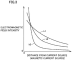
- Fig. 3 represents the relationship between the distance from a current source (magnetic current source) and the electromagnetic field intensity.
- the electric magnetic field is composed of three components.
- Curve k1 represents a component inversely proportional to the distance from the wave source, and is referred to as "radiation electromagnetic field ".
- Curve k2 represents a component inversely proportional to the square of the distance from the wave source, and is referred to as "induction electromagnetic field”.
- Curve k3 represents a component inversely proportional to the cube of the distance from the wave source, and is referred to as "electrostatic electromagnetic field".
- the resonance method energy (electric power) is transmitted taking advantage of the near field (evanescent field).
- a pair of resonators having the same natural frequency for example, a pair of LC resonant coils
- the resonance method allows power transmission with lower energy loss as compared to an electromagnetic wave that transmits energy (electric power) by the "radiation electromagnetic field" that passes on energy over a great distance.
- Fig. 4 is a block diagram representing a powertrain configuration of hybrid vehicle 100 of Fig. 1 .
- hybrid vehicle 100 includes a power storage device 120, a system main relay SMR1, a boost converter 410, inverters 420, 422, motor generators 430, 432, an engine 434, a power split device 436, a driving wheel 438 and a vehicle ECU 440. Additionally, hybrid vehicle 100 further includes secondary self-resonant coil 450, secondary coil 452, rectifier 460, and system main relay SMR2.
- Hybrid vehicle 100 incorporates engine 434 and motor generator 432 as the driving source.
- Engine 434 and motor generators 430 and 432 are coupled with power split device 436.
- Hybrid vehicle 100 runs by the driving power generated by at least one of engine 434 and motor generator 432.
- the power generated by engine 434 is divided into two paths by power split device 436. Specifically, one path is directed to driving wheel 438, and the other path is directed to motor generator 430.
- Motor generator 430 is an AC rotating electric machine formed of, for example, a 3-phase AC synchronous electric motor having a permanent magnet embedded in a rotor. Motor generator 430 generates electric power using the kinetic energy of engine 434 divided by power split device 436. For example, when the SOC of power storage device 120 is reduced, engine 434 is started and electric power is generated by motor generator 430, whereby power storage device 120 is charged.
- Motor generator 432 is also an AC rotating electric machine formed of, for example, a 3-phase AC synchronous electric motor having a permanent magnet embedded in a rotor, likewise with motor generator 430. Motor generator 432 generates driving power using at least one of the electric power stored at power storage device 120 and the electric power generated by motor generator 430. The driving power of motor generator 432 is transmitted to driving wheel 438.
- motor generator 432 In a braking mode of the vehicle or in an acceleration reducing mode at a downward slope, the mechanical energy stored at the vehicle as a kinetic energy or potential energy is used for the rotational drive of motor generator 432 through driving wheel 438, whereby motor generator 432 operates as a power generator. Accordingly, motor generator 432 operates as a regenerative brake converting the running energy into electric power to generate the braking force.
- the electric power generated by motor generator 432 is stored in power storage device 120.
- Power split device 436 is formed of a planetary gear set including a sun gear, a pinion gear, a carrier, and a ring gear.
- the pinion gear engages with the sun gear and ring gear.
- the carrier supports the pinion gear to allow rotation on its axis, and is coupled to the crankshaft of engine 434.
- the sun gear is coupled to the rotational shaft of motor generator 430.
- the ring gear is coupled to the rotational shaft of motor generator 432 and to driving wheel 438.
- System main relay SMR1 is disposed between power storage device 120 and boost converter 410.
- System main relay SMR1 is set on/off according to a signal SE1 from vehicle ECU 440.
- Boost converter 410 responds to a signal PWC from vehicle ECU 440 to boost the voltage output from power storage device 120 for output onto positive line PL2.
- a DC chopper circuit for example, constitutes this boost converter 410.
- Inverters 420 and 422 are provided corresponding to motor generators 430 and 432, respectively. Inverter 420 responds to a signal PWI1 from vehicle ECU 440 to drive motor generator 430. Inverter 422 responds to a signal PWI2 to drive motor generator 432.
- a 3-phase bridge circuit for example, constitutes each of inverters 420 and 422.
- Boost converter 410, inverters 420, 422, motor generators 430, 432, engine 434, and power split device 436 constitute driving power generation unit 110 of Fig. 1 .
- Secondary self-resonant coil 450 is an LC resonant coil having both ends open (non-connected) and receives the electric power from power feeding device 500 by resonating with the primary self-resonant coil included in power transmission unit 520 of power feeding device 500 ( Fig. 1 ) via an electromagnetic field.
- the capacitor component of secondary self-resonant coil 450 the floating capacitance of the coil may be employed, or a capacitor may be provided connected across the ends of the coil.
- Secondary self-resonant coil 450 has its number of windings set appropriately such that the Q value representing the resonance strength between the primary self-resonant coil of power feeding device 500 and secondary self-resonant coil 450 (for example, Q > 100), the ⁇ value representing the degree of coupling thereof and the like become higher based on the distance from the primary self-resonant coil, the resonant frequency of the primary self-resonant coil and secondary self-resonant coil 450, and the like.
- Secondary coil 452 is arranged coaxial with secondary self-resonant coil 450, and can be coupled magnetically with secondary self-resonant coil 450 by electromagnetic induction. Secondary coil 452 extracts the electric power received by secondary self-resonant coil 450 through electromagnetic induction for output to rectifier 460. Secondary self-resonant coil 450 and secondary coil 452 constitute power reception unit 130 shown in Fig. 1 .
- Rectifier 460 rectifies AC power extracted by secondary coil 452.
- System main relay SMR2 is arranged between rectifier 460 and power storage device 120.
- System main relay SMR2 is set on/off according to a signal SE2 from vehicle ECU 440.
- a DC/DC converter for adjusting the voltage of the electric power rectified by rectifier 460 may be provided between rectifier 460 and system main relay SMR2, or between system main relay SMR2 and power storage device 120.
- Vehicle ECU 440 generates signals PWC, PWI1 and PWI2 to drive boost converter 410, motor generator 430, and motor generator 432, respectively, based on the accelerator pedal position, vehicle speed, and signals from various sensors.
- the generated signals PWC, PWI1 and PWI2 are output to boost converter 410, inverter 420, and inverter 422, respectively.
- vehicle ECU 440 In a vehicle running mode, vehicle ECU 440 sets system main relays SMR1 and SMR2 on and off, respectively. In the case where electric power can be received from power feeding device 500 ( Fig. 1 ) during a running mode of the vehicle, vehicle ECU 440 may set system main relays SMR1 and SMR2 both on. In a power reception mode from power feeding device 500 external to the vehicle, vehicle ECU 440 sets system main relays SMR1 and SMR2 off and on, respectively.
- power reception unit 130 is stored in and located at the bottom of engine room 140. Since shielding member 150 is provided at the inner surface, for example, of engine room 140 where power reception unit 130 is stored, it is not necessary to additionally provide an exclusive shielding box or the like for storing power reception unit 130. According to the first embodiment, the mounting space of power reception unit 130 can be reduced, and blocking of the leakage electromagnetic field generated at the time of power reception can be realized at low cost.
- shielding member 150 is provided at engine room 140 where power reception unit 130 is stored instead of providing a shielding structure at power reception unit 130 per se in the first embodiment, a long distance can be taken between power reception unit 130 and shielding member 150 (shielding distance), whereby reflected power is suppressed. According to the first embodiment, reduction in efficiency caused by providing a shielding structure can be suppressed.
- the second embodiment has an interlock mechanism provided to interrupt power reception from power feeding device 500, if currently receiving electric power, or to prohibit power reception, if in a non-power reception mode, when the hood of engine room 140 where power reception unit 130 is stored is opened.
- Fig. 5 represents an entire configuration indicating characteristic portions of a hybrid vehicle shown as an example of an electrical powered vehicle according to the second embodiment.
- this hybrid vehicle 100A further includes an open/close sensor 180, and a communication device 190, in the configuration of hybrid vehicle 100 of Fig. 1 .
- Open/close sensor 180 detects the open/close state of the hood, and outputs the detection result to communication device 190.
- communication device 190 transmits wirelessly to power feeding device 500 a signal designating interruption of power feeding from power feeding device 500 to hybrid vehicle 100A, if in a power feeding mode, or a signal designating prohibition of power feeding, if in a non-power feeding mode.
- high frequency power source 510 of power feeding device 500 Upon receiving a signal designating interruption or prohibition of power feeding from communication device 190 of hybrid vehicle 100A, high frequency power source 510 of power feeding device 500 stops power feeding towards power transmission unit 520.
- an interlock mechanism in the second embodiment for interrupting or prohibiting power feeding from power feeding device 500 when the hood of engine room 140 where power reception unit 130 is stored is opened, the emission of the leakage electromagnetic field generated at the time of power reception from power feeding device 500, outside of engine room 140, can be prevented.
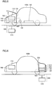
- Fig. 6 represents an entire configuration indicating characteristic portions of a hybrid vehicle shown as an example of an electrical powered vehicle according to a third embodiment.
- power storage device 120 is provided below a floor 220 of trunk room 210.
- Power reception unit 130 receiving electric power from power feeding device 500 is stored in trunk room 210.
- power reception unit 130 is arranged below power storage device 120, and at the bottom of trunk room 210.
- shielding member 230 is provided to electromagnetically shield trunk room 210 from inside and outside.
- shielding member 230 is formed of a cloth, sponge, or the like having an electromagnetic shielding effect, and is attached to the inner surface of trunk room 210.
- the bottom of trunk room 210 is opened at the site where at least power reception unit 130 is provided. Shielding member 230 is not provided at that opening.
- hybrid vehicle 100B The remaining configuration of hybrid vehicle 100B is similar to that of hybrid vehicle 100 according to the first embodiment shown in Fig. 1 .
- the configuration of power feeding device 500 is also similar to that of the first embodiment.
- power reception unit 130 is stored in trunk room 210, and arranged at the bottom of trunk room 210.
- Shielding member 230 is provided at the inner surface, for example, of trunk room 210 where power reception unit 130 is stored. Accordingly, the space for mounting power reception unit 130 can be saved since it is not necessary to additionally provide an exclusive shielding box or the like for storing power reception unit 130. Since a long distance (shielding distance) can be taken between the power reception unit (secondary self-resonant coil) and the shielding member, reduction in efficiency caused by providing a shielding structure can be suppressed, likewise with the first embodiment.
- the third embodiment can achieve effects similar to those of the first embodiment set forth above.
- the efficiency can be further improved according to the third embodiment since the wiring length between power storage device 120 and power reception unit 130 can be shortened.
- the present fourth embodiment has an interlock mechanism provided to interrupt power reception from power feeding device 500, if currently receiving electric power, or to prohibit power reception, if in a non-power reception mode, when trunk room 210 where power reception unit 130 is stored is opened, likewise with the second embodiment with respect to the first embodiment.
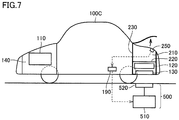
- Fig. 7 represents an entire configuration indicating characteristic portions of a hybrid vehicle shown as an example of an electrical powered vehicle according to the fourth embodiment.
- this hybrid vehicle 100C further includes an open/close sensor 250, and a communication device 190, in the configuration of hybrid vehicle 100B according to the third embodiment shown in Fig. 6 .
- Open/close sensor 250 detects the open/close state of trunk room 210, and outputs the detection result to communication device 190.
- communication device 190 transmits wirelessly to power feeding device 500 a signal designating interruption of power feeding from power feeding device 500 to hybrid vehicle 100C, if in a power feeding mode, or a signal designating prohibition of power feeding, if in a non-power feeding mode.
- an interlock mechanism in the fourth embodiment for interrupting or prohibiting power feeding from power feeding device 500 when trunk room 210 where power reception unit 130 is stored is opened, the emission of the leakage electromagnetic field generated at the time of power reception from power feeding device 500, outside of trunk room 210, can be prevented.
- each of the above embodiments is directed to power transmission by causing resonance between a primary self-resonant coil included in power transmission unit 520 of power feeding device 500 and a secondary self-resonant coil included in power reception unit 130 of the vehicle side
- a pair of high dielectric disks may be used for the resonators.
- the high dielectric disk is formed of a material of high permittivity such as TiO 2 , BaTi 4 O 9 , and LiTaO 3 .
- an electrical powered vehicle As an example of an electrical powered vehicle according to the present invention, a series/parallel type hybrid vehicle where the driving power of engine 434 is split by power split device 436 to be transmitted to driving wheel 438 and motor generator 430 has been described.
- the present invention is also applicable to other types of vehicle.
- the present invention is applicable to the so-called series type hybrid vehicle using engine 434 only for driving motor generator 430, and the driving power of the vehicle is generated by motor generator 432 alone, a hybrid vehicle having only the regenerative energy among the kinetic energy generated by engine 434 collected as electric energy, a motor assistant type hybrid vehicle using the engine as the main driving source and assisted by the motor as necessary, and the like.
- the present invention is applicable to an electric vehicle that runs only by electric power, lacking an engine 434, or a fuel cell vehicle further including a fuel battery in addition to power storage device 120 as the DC power source.
- a configuration may be employed in which power reception unit 130 is stored in a chamber where a motor generator generating running driving power and/or an electric power conversion device (inverter, boost converter, and the like) performing electric power conversion between the power storage device and motor generator are stored, and shield that chamber.
- the present invention is applicable to an electrical powered vehicle lacking a boost converter 410.
- motor generator 432 corresponds to "electric motor” of the present invention.
- Engine room 140 of the first and second embodiments and trunk room 210 of the third and fourth embodiments correspond to the "storage chamber” of the present invention.
- Engine 434 corresponds to the "internal combustion engine” of the present invention.
- Engine room 140 corresponds to the "engine room” of the present invention.
- Trunk room 210 corresponds to the "luggage compartment” of the present invention.
- Open/close sensors 180 and 250 correspond to the "detection device" of the present invention.
Landscapes
- Engineering & Computer Science (AREA)
- Power Engineering (AREA)
- Computer Networks & Wireless Communication (AREA)
- Transportation (AREA)
- Mechanical Engineering (AREA)
- Sustainable Energy (AREA)
- Life Sciences & Earth Sciences (AREA)
- Sustainable Development (AREA)
- Electromagnetism (AREA)
- Physics & Mathematics (AREA)
- Electric Propulsion And Braking For Vehicles (AREA)
- Hybrid Electric Vehicles (AREA)
- Arrangement Or Mounting Of Propulsion Units For Vehicles (AREA)
- Charge And Discharge Circuits For Batteries Or The Like (AREA)
- Current-Collector Devices For Electrically Propelled Vehicles (AREA)
Claims (7)
- Véhicule à propulsion électrique capable de générer de l'énergie d'entraînement de déplacement grâce à un moteur électrique (432) en utilisant de l'énergie électrique délivrée à partir d'un dispositif d'alimentation en énergie (500) prévu à l'extérieur du véhicule, comportant :une unité de réception d'énergie (130) comprenant un résonateur de réception d'énergie qui reçoit de l'énergie électrique provenant d'un résonateur de transmission d'énergie inclus dans ledit dispositif d'alimentation en énergie en résonnant avec ledit résonateur de transmission d'énergie par l'intermédiaire d'un champ électromagnétique ;une chambre de stockage (140, 210) où ladite unité de réception d'énergie est logée ;un élément de blindage (150, 230) destiné à blinder de manière électromagnétique ladite chambre de stockage de l'intérieur et de l'extérieur ; caractérisé en ce que ledit véhicule comporte en outre :une porte pour ouvrir et fermer ladite chambre de stockage ; etun dispositif de blocage (180, 250, 190) destiné à empêcher le champ électromagnétique d'être déchargé à l'extérieur de ladite chambre de stockage à travers ladite porte quand ladite porte atteint un état ouvert, dans lequel ledit dispositif de blocage comprend un dispositif (180, 250, 190) destiné à interrompre ou empêcher une réception d'énergie provenant dudit dispositif d'alimentation en énergie quand ladite porte atteint un état ouvert, et ledit dispositif de blocage comprend :un dispositif de détection (180, 250) qui détecte un état ouvert/fermé de ladite porte, etun dispositif de communication (190) qui transmet audit dispositif d'alimentation en énergie une commande qui désigne une interruption ou une interdiction de transmission d'énergie à partir dudit dispositif d'alimentation en énergie quand un état ouvert de ladite porte est détecté par ledit dispositif de détection.
- Véhicule à propulsion électrique capable de générer de l'énergie d'entraînement de déplacement grâce à un moteur électrique (432) en utilisant de l'énergie électrique délivrée à partir d'un dispositif d'alimentation en énergie (500) prévu à l'extérieur du véhicule, comportant :une unité de réception d'énergie (130) comprenant un résonateur de réception d'énergie recevant de l'énergie électrique provenant d'un résonateur de transmission d'énergie inclus dans ledit dispositif d'alimentation en énergie en résonnant avec ledit résonateur de transmission d'énergie par l'intermédiaire d'un champ électromagnétique ;une chambre de stockage (140, 210) où ladite unité de réception d'énergie est logée ;un élément de blindage (150, 230) destiné à blinder de manière électromagnétique ladite chambre de stockage de l'intérieur et de l'extérieur ; caractérisé en ce que ledit véhicule comporte en outre :une porte pour ouvrir et fermer ladite chambre de stockage ; etun dispositif de blocage (180, 250, 190) destiné à empêcher le champ électromagnétique d'être déchargé à l'extérieur de ladite chambre de stockage à travers ladite porte quand ladite porte atteint un état ouvert,dans lequel ledit dispositif de blocage comprend un dispositif (180, 250, 190) destiné à interrompre ou empêcher une réception d'énergie provenant dudit dispositif d'alimentation en énergie quand ladite porte atteint un état ouvert,dans lequel ledit dispositif de blocage comprend une plaque de blindage qui se trouve entre ledit dispositif d'alimentation en énergie et ladite unité de réception d'énergie quand un état ouvert de ladite porte est détecté.
- Véhicule à propulsion électrique selon la revendication 1 ou 2, comportant en outre un moteur à combustion interne (434) qui génère de l'énergie pour le déplacement,
dans lequel ladite chambre de stockage est un compartiment moteur (140) où ledit moteur à combustion interne est logé. - Véhicule à propulsion électrique selon la revendication 1 ou 2, dans lequel ladite chambre de stockage est un compartiment à bagages (210) pour le stockage des bagages d'un usager.
- Véhicule à propulsion électrique selon la revendication 1 ou 2, dans lequel ladite chambre de stockage est une chambre où ledit moteur électrique est logé.
- Véhicule à propulsion électrique selon la revendication 1 ou 2, comportant en outre un dispositif de conversion d'énergie électrique (410, 420, 422) qui réalise une conversion de puissance entre une ligne d'alimentation dans le véhicule et ledit moteur électrique,
dans lequel ladite chambre de stockage est une chambre où ledit dispositif de conversion de puissance est logé. - Véhicule à propulsion électrique selon l'une quelconque des revendications 1 à 6, dans lequel ladite unité de réception d'énergie est disposée au fond de ladite chambre de stockage.
Applications Claiming Priority (1)
| Application Number | Priority Date | Filing Date | Title |
|---|---|---|---|
| PCT/JP2008/068359 WO2010041320A1 (fr) | 2008-10-09 | 2008-10-09 | Véhicule électrique |
Publications (3)
| Publication Number | Publication Date |
|---|---|
| EP2345552A1 EP2345552A1 (fr) | 2011-07-20 |
| EP2345552A4 EP2345552A4 (fr) | 2014-05-07 |
| EP2345552B1 true EP2345552B1 (fr) | 2019-11-20 |
Family
ID=42100285
Family Applications (1)
| Application Number | Title | Priority Date | Filing Date |
|---|---|---|---|
| EP08877268.6A Active EP2345552B1 (fr) | 2008-10-09 | 2008-10-09 | Véhicule électrique |
Country Status (5)
| Country | Link |
|---|---|
| US (1) | US8651208B2 (fr) |
| EP (1) | EP2345552B1 (fr) |
| JP (1) | JP4962620B2 (fr) |
| CN (1) | CN102177043A (fr) |
| WO (1) | WO2010041320A1 (fr) |
Families Citing this family (32)
| Publication number | Priority date | Publication date | Assignee | Title |
|---|---|---|---|---|
| DE102010004549B4 (de) * | 2010-01-14 | 2020-06-18 | Dr. Ing. H.C. F. Porsche Aktiengesellschaft | Kraftfahrzeug |
| WO2012111088A1 (fr) * | 2011-02-15 | 2012-08-23 | トヨタ自動車株式会社 | Véhicule et dispositif d'alimentation externe |
| JP5690642B2 (ja) * | 2011-04-22 | 2015-03-25 | 矢崎総業株式会社 | 共鳴式非接触給電システム、共鳴式非接触給電システムの送電側装置及び車載充電装置 |
| JP5857795B2 (ja) * | 2011-05-17 | 2016-02-10 | 日産自動車株式会社 | 非接触充電器の取付構造 |
| JP2012254781A (ja) * | 2011-05-17 | 2012-12-27 | Nissan Motor Co Ltd | 非接触充電器の取付構造 |
| JP2012248747A (ja) * | 2011-05-30 | 2012-12-13 | Toyota Industries Corp | 共鳴型非接触給電システムのシールド装置 |
| CN103975400B (zh) * | 2011-11-18 | 2017-07-11 | 丰田自动车株式会社 | 输电装置、受电装置及电力传输系统 |
| EP2783891B1 (fr) * | 2011-11-25 | 2019-12-25 | Toyota Jidosha Kabushiki Kaisha | Véhicule |
| JP5834825B2 (ja) * | 2011-11-25 | 2015-12-24 | トヨタ自動車株式会社 | 車両 |
| JP2013112237A (ja) * | 2011-11-30 | 2013-06-10 | Honda Motor Co Ltd | パワーコントロールユニット |
| DE102011088112A1 (de) * | 2011-12-09 | 2013-06-13 | Bayerische Motoren Werke Aktiengesellschaft | Kraftwagen |
| KR20150054836A (ko) * | 2012-11-15 | 2015-05-20 | 쥬코쿠 덴료쿠 가부시키 가이샤 | 비접촉 급전 시스템, 및 비접촉 급전 시스템의 제어 방법 |
| CN104662772A (zh) * | 2012-11-15 | 2015-05-27 | 中国电力株式会社 | 非接触供电系统以及非接触供电系统的控制方法 |
| US9533589B2 (en) * | 2013-07-16 | 2017-01-03 | Qualcomm Incorporated | Integration of electronic components in inductive power transfer systems |
| EP3056380A4 (fr) * | 2013-09-10 | 2017-04-19 | The Chugoku Electric Power Co., Inc. | Système d'alimentation en énergie sans contact, et procédé d'alimentation en énergie sans contact |
| CN105593053A (zh) * | 2013-09-27 | 2016-05-18 | 日产自动车株式会社 | 非接触受电装置的车载构造 |
| US10320230B2 (en) | 2014-03-26 | 2019-06-11 | Apple Inc. | Temperature management for inductive charging systems |
| US10106045B2 (en) | 2014-10-27 | 2018-10-23 | At&T Intellectual Property I, L.P. | Methods and apparatus to charge a vehicle and to facilitate communications with the vehicle |
| FR3028106B1 (fr) * | 2014-11-05 | 2018-02-02 | Whylot | Procede de rechargement d'une batterie electrique de traction d'un vehicule automobile par un element integre a un moteur electrique de traction se trouvant dans le vehicule automobile |
| US9537321B2 (en) | 2015-02-25 | 2017-01-03 | Motorola Solutions, Inc. | Method and apparatus for power transfer for a portable electronic device |
| US10343537B2 (en) * | 2016-03-08 | 2019-07-09 | Witricity Corporation | Method and apparatus for positioning a vehicle |
| JP6294903B2 (ja) * | 2016-03-22 | 2018-03-14 | 株式会社Subaru | 車両 |
| KR101848416B1 (ko) * | 2016-05-18 | 2018-04-12 | 주식회사 아모그린텍 | 차량용 무선 전력 송신장치 |
| JP6546956B2 (ja) * | 2017-04-28 | 2019-07-17 | 株式会社Subaru | 車両 |
| JP6508272B2 (ja) * | 2017-09-20 | 2019-05-08 | トヨタ自動車株式会社 | 車両 |
| JP7165047B2 (ja) * | 2018-12-21 | 2022-11-02 | 株式会社Subaru | 電動車両 |
| JP7124804B2 (ja) * | 2019-07-25 | 2022-08-24 | 株式会社デンソー | 車両 |
| CN112706601A (zh) * | 2020-12-16 | 2021-04-27 | 浙江零跑科技有限公司 | 无线电池包组件、无线电池包车辆、无线电池包充电组件 |
| JP7504040B2 (ja) * | 2021-02-12 | 2024-06-21 | ダイハツ工業株式会社 | 車載用制御装置 |
| JP7487705B2 (ja) * | 2021-04-30 | 2024-05-21 | トヨタ自動車株式会社 | フロア構造 |
| JP7760422B2 (ja) * | 2022-03-22 | 2025-10-27 | 本田技研工業株式会社 | 車両電源システム |
| CN115534709A (zh) * | 2022-11-01 | 2022-12-30 | 广州大学 | 一种车用无线充电蓄电系统 |
Citations (1)
| Publication number | Priority date | Publication date | Assignee | Title |
|---|---|---|---|---|
| JP3101001B2 (ja) * | 1991-06-20 | 2000-10-23 | 本田技研工業株式会社 | バッテリの残容量警報装置 |
Family Cites Families (29)
| Publication number | Priority date | Publication date | Assignee | Title |
|---|---|---|---|---|
| US4800328A (en) * | 1986-07-18 | 1989-01-24 | Inductran Inc. | Inductive power coupling with constant voltage output |
| JP2996559B2 (ja) * | 1992-01-29 | 2000-01-11 | 本田技研工業株式会社 | 電気自動車の充電状況表示システム |
| JP2948040B2 (ja) | 1993-01-12 | 1999-09-13 | 株式会社日立製作所 | 発熱抵抗式空気流量計 |
| JPH07170612A (ja) | 1993-12-10 | 1995-07-04 | Fujitsu Ten Ltd | 電池充電システム |
| JPH089512A (ja) | 1994-06-23 | 1996-01-12 | Toyota Autom Loom Works Ltd | 電動車用電磁給電装置 |
| JPH08237890A (ja) | 1995-02-28 | 1996-09-13 | Fuji Electric Co Ltd | 自動車への非接触式電力供給装置 |
| JPH11273977A (ja) | 1998-03-20 | 1999-10-08 | Toyota Autom Loom Works Ltd | 電気自動車用電磁誘導型非接触給電装置 |
| JP3891533B2 (ja) | 1998-11-16 | 2007-03-14 | アイシン・エィ・ダブリュ株式会社 | 駆動装置 |
| JP4160987B2 (ja) | 1998-11-16 | 2008-10-08 | アイシン・エィ・ダブリュ株式会社 | 駆動装置 |
| JP2001177915A (ja) | 1999-12-10 | 2001-06-29 | Toyota Motor Corp | エネルギー授受装置 |
| JP2001294048A (ja) * | 2000-04-13 | 2001-10-23 | Toyota Motor Corp | 車両用電源装置 |
| JP2002291113A (ja) | 2001-03-27 | 2002-10-04 | Zero Sports Co Ltd | 電気自動車 |
| JP3870315B2 (ja) * | 2001-08-08 | 2007-01-17 | 株式会社日立製作所 | 移動体システム |
| JP2004229421A (ja) * | 2003-01-23 | 2004-08-12 | Toyota Motor Corp | 車両 |
| JP2005101392A (ja) | 2003-09-26 | 2005-04-14 | Aichi Electric Co Ltd | 非接触給電装置 |
| JP4036813B2 (ja) | 2003-09-30 | 2008-01-23 | シャープ株式会社 | 非接触電力供給システム |
| US7451839B2 (en) * | 2005-05-24 | 2008-11-18 | Rearden, Llc | System and method for powering a vehicle using radio frequency generators |
| KR101118710B1 (ko) | 2005-07-12 | 2012-03-13 | 메사추세츠 인스티튜트 오브 테크놀로지 | 무선 비-방사성 에너지 전달 |
| US7825543B2 (en) | 2005-07-12 | 2010-11-02 | Massachusetts Institute Of Technology | Wireless energy transfer |
| JP4865451B2 (ja) * | 2006-08-24 | 2012-02-01 | 三菱重工業株式会社 | 受電装置及び送電装置並びに車両 |
| EP2078330A2 (fr) * | 2006-10-25 | 2009-07-15 | Laszlo Farkas | Systeme de transfert d'energie resonant sans fil a haute puissance |
| KR101356409B1 (ko) | 2007-03-27 | 2014-01-27 | 메사추세츠 인스티튜트 오브 테크놀로지 | 무선 에너지 전달 |
| JP2008289273A (ja) * | 2007-05-17 | 2008-11-27 | Toyota Motor Corp | 給電システムおよび車両 |
| JP4453741B2 (ja) * | 2007-10-25 | 2010-04-21 | トヨタ自動車株式会社 | 電動車両および車両用給電装置 |
| US8729734B2 (en) * | 2007-11-16 | 2014-05-20 | Qualcomm Incorporated | Wireless power bridge |
| WO2009114671A1 (fr) * | 2008-03-13 | 2009-09-17 | Access Business Group International Llc | Système d’alimentation de puissance inductive à pluralité de primaires de bobine |
| US8421409B2 (en) * | 2008-09-19 | 2013-04-16 | Toyota Jidosha Kabushiki Kaisha | Noncontact power receiving apparatus for electrically-powered vehicle and vehicle including the same |
| CN102171777A (zh) * | 2008-10-02 | 2011-08-31 | 丰田自动车株式会社 | 自谐振线圈、非接触电力传输装置以及车辆 |
| US20100201309A1 (en) * | 2009-02-10 | 2010-08-12 | Meek Ivan C | Systems and methods for coupling a vehicle to an external grid and/or network |
-
2008
- 2008-10-09 US US13/122,841 patent/US8651208B2/en active Active
- 2008-10-09 JP JP2010532737A patent/JP4962620B2/ja not_active Expired - Fee Related
- 2008-10-09 EP EP08877268.6A patent/EP2345552B1/fr active Active
- 2008-10-09 CN CN2008801314704A patent/CN102177043A/zh active Pending
- 2008-10-09 WO PCT/JP2008/068359 patent/WO2010041320A1/fr not_active Ceased
Patent Citations (1)
| Publication number | Priority date | Publication date | Assignee | Title |
|---|---|---|---|---|
| JP3101001B2 (ja) * | 1991-06-20 | 2000-10-23 | 本田技研工業株式会社 | バッテリの残容量警報装置 |
Also Published As
| Publication number | Publication date |
|---|---|
| EP2345552A4 (fr) | 2014-05-07 |
| US20110214926A1 (en) | 2011-09-08 |
| WO2010041320A1 (fr) | 2010-04-15 |
| CN102177043A (zh) | 2011-09-07 |
| US8651208B2 (en) | 2014-02-18 |
| JP4962620B2 (ja) | 2012-06-27 |
| EP2345552A1 (fr) | 2011-07-20 |
| JPWO2010041320A1 (ja) | 2012-03-01 |
Similar Documents
| Publication | Publication Date | Title |
|---|---|---|
| EP2345552B1 (fr) | Véhicule électrique | |
| EP2407338B1 (fr) | Véhicule électrique | |
| EP2360049B1 (fr) | Véhicule électrique | |
| EP3415359B1 (fr) | Véhicule électrique et dispositif d'alimentation électrique pour véhicule | |
| EP2345553B1 (fr) | Dispositif de transmission d énergie sans contact et véhicule équipé de celui-ci | |
| EP2346142B1 (fr) | Dispositif de reception d' energie sans contact et vehicule equipe de celui-ci | |
| EP2346141B1 (fr) | Système d' alimentation en courant | |
| EP2431213B1 (fr) | Unité de charge de véhicule | |
| EP2576273B1 (fr) | Système d'alimentation d'énergie et véhicule | |
| JP5304624B2 (ja) | 給電装置、車両および車両給電システム | |
| RU2461946C1 (ru) | Устройство бесконтактного получения энергии и транспортное средство, содержащее такое устройство | |
| CN102897040B (zh) | 电动车辆 | |
| JP2015027224A (ja) | 非接触受電装置 |
Legal Events
| Date | Code | Title | Description |
|---|---|---|---|
| PUAI | Public reference made under article 153(3) epc to a published international application that has entered the european phase |
Free format text: ORIGINAL CODE: 0009012 |
|
| 17P | Request for examination filed |
Effective date: 20110509 |
|
| AK | Designated contracting states |
Kind code of ref document: A1 Designated state(s): AT BE BG CH CY CZ DE DK EE ES FI FR GB GR HR HU IE IS IT LI LT LU LV MC MT NL NO PL PT RO SE SI SK TR |
|
| AX | Request for extension of the european patent |
Extension state: AL BA MK RS |
|
| DAX | Request for extension of the european patent (deleted) | ||
| RAP1 | Party data changed (applicant data changed or rights of an application transferred) |
Owner name: TOYOTA JIDOSHA KABUSHIKI KAISHA |
|
| A4 | Supplementary search report drawn up and despatched |
Effective date: 20140403 |
|
| RIC1 | Information provided on ipc code assigned before grant |
Ipc: B60L 11/12 20060101ALI20140328BHEP Ipc: H02J 7/02 20060101ALI20140328BHEP Ipc: H01F 38/14 20060101ALI20140328BHEP Ipc: B60L 11/18 20060101ALI20140328BHEP Ipc: H02J 17/00 20060101ALI20140328BHEP Ipc: H02J 5/00 20060101ALI20140328BHEP Ipc: B60L 11/14 20060101ALI20140328BHEP Ipc: H02J 7/00 20060101ALI20140328BHEP Ipc: B60L 5/00 20060101AFI20140328BHEP |
|
| RIN1 | Information on inventor provided before grant (corrected) |
Inventor name: ICHIKAWA, SHINJI |
|
| RIN1 | Information on inventor provided before grant (corrected) |
Inventor name: ICHIKAWA, SHINJI |
|
| STAA | Information on the status of an ep patent application or granted ep patent |
Free format text: STATUS: EXAMINATION IS IN PROGRESS |
|
| 17Q | First examination report despatched |
Effective date: 20170303 |
|
| REG | Reference to a national code |
Ref country code: DE Ref legal event code: R079 Ref document number: 602008061692 Country of ref document: DE Free format text: PREVIOUS MAIN CLASS: B60L0005000000 Ipc: B60L0050000000 |
|
| RIC1 | Information provided on ipc code assigned before grant |
Ipc: H02J 50/12 20160101ALI20190307BHEP Ipc: H02J 50/70 20160101ALI20190307BHEP Ipc: B60L 50/00 20190101AFI20190307BHEP Ipc: H02J 50/80 20160101ALI20190307BHEP Ipc: B60L 50/62 20190101ALI20190307BHEP Ipc: H02J 5/00 20160101ALI20190307BHEP Ipc: B60L 50/16 20190101ALI20190307BHEP Ipc: B60L 53/12 20190101ALI20190307BHEP Ipc: H02J 7/02 20160101ALI20190307BHEP Ipc: B60L 5/00 20060101ALI20190307BHEP Ipc: B60L 15/20 20060101ALI20190307BHEP Ipc: B60L 15/02 20060101ALI20190307BHEP |
|
| GRAP | Despatch of communication of intention to grant a patent |
Free format text: ORIGINAL CODE: EPIDOSNIGR1 |
|
| STAA | Information on the status of an ep patent application or granted ep patent |
Free format text: STATUS: GRANT OF PATENT IS INTENDED |
|
| INTG | Intention to grant announced |
Effective date: 20190613 |
|
| GRAS | Grant fee paid |
Free format text: ORIGINAL CODE: EPIDOSNIGR3 |
|
| GRAA | (expected) grant |
Free format text: ORIGINAL CODE: 0009210 |
|
| STAA | Information on the status of an ep patent application or granted ep patent |
Free format text: STATUS: THE PATENT HAS BEEN GRANTED |
|
| AK | Designated contracting states |
Kind code of ref document: B1 Designated state(s): AT BE BG CH CY CZ DE DK EE ES FI FR GB GR HR HU IE IS IT LI LT LU LV MC MT NL NO PL PT RO SE SI SK TR |
|
| REG | Reference to a national code |
Ref country code: GB Ref legal event code: FG4D |
|
| REG | Reference to a national code |
Ref country code: CH Ref legal event code: EP |
|
| REG | Reference to a national code |
Ref country code: DE Ref legal event code: R096 Ref document number: 602008061692 Country of ref document: DE |
|
| REG | Reference to a national code |
Ref country code: IE Ref legal event code: FG4D |
|
| REG | Reference to a national code |
Ref country code: AT Ref legal event code: REF Ref document number: 1203809 Country of ref document: AT Kind code of ref document: T Effective date: 20191215 |
|
| REG | Reference to a national code |
Ref country code: DE Ref legal event code: R084 Ref document number: 602008061692 Country of ref document: DE |
|
| REG | Reference to a national code |
Ref country code: NL Ref legal event code: MP Effective date: 20191120 |
|
| REG | Reference to a national code |
Ref country code: LT Ref legal event code: MG4D |
|
| PG25 | Lapsed in a contracting state [announced via postgrant information from national office to epo] |
Ref country code: NO Free format text: LAPSE BECAUSE OF FAILURE TO SUBMIT A TRANSLATION OF THE DESCRIPTION OR TO PAY THE FEE WITHIN THE PRESCRIBED TIME-LIMIT Effective date: 20200220 Ref country code: FI Free format text: LAPSE BECAUSE OF FAILURE TO SUBMIT A TRANSLATION OF THE DESCRIPTION OR TO PAY THE FEE WITHIN THE PRESCRIBED TIME-LIMIT Effective date: 20191120 Ref country code: BG Free format text: LAPSE BECAUSE OF FAILURE TO SUBMIT A TRANSLATION OF THE DESCRIPTION OR TO PAY THE FEE WITHIN THE PRESCRIBED TIME-LIMIT Effective date: 20200220 Ref country code: SE Free format text: LAPSE BECAUSE OF FAILURE TO SUBMIT A TRANSLATION OF THE DESCRIPTION OR TO PAY THE FEE WITHIN THE PRESCRIBED TIME-LIMIT Effective date: 20191120 Ref country code: LV Free format text: LAPSE BECAUSE OF FAILURE TO SUBMIT A TRANSLATION OF THE DESCRIPTION OR TO PAY THE FEE WITHIN THE PRESCRIBED TIME-LIMIT Effective date: 20191120 Ref country code: GR Free format text: LAPSE BECAUSE OF FAILURE TO SUBMIT A TRANSLATION OF THE DESCRIPTION OR TO PAY THE FEE WITHIN THE PRESCRIBED TIME-LIMIT Effective date: 20200221 Ref country code: ES Free format text: LAPSE BECAUSE OF FAILURE TO SUBMIT A TRANSLATION OF THE DESCRIPTION OR TO PAY THE FEE WITHIN THE PRESCRIBED TIME-LIMIT Effective date: 20191120 Ref country code: NL Free format text: LAPSE BECAUSE OF FAILURE TO SUBMIT A TRANSLATION OF THE DESCRIPTION OR TO PAY THE FEE WITHIN THE PRESCRIBED TIME-LIMIT Effective date: 20191120 Ref country code: LT Free format text: LAPSE BECAUSE OF FAILURE TO SUBMIT A TRANSLATION OF THE DESCRIPTION OR TO PAY THE FEE WITHIN THE PRESCRIBED TIME-LIMIT Effective date: 20191120 |
|
| PG25 | Lapsed in a contracting state [announced via postgrant information from national office to epo] |
Ref country code: IS Free format text: LAPSE BECAUSE OF FAILURE TO SUBMIT A TRANSLATION OF THE DESCRIPTION OR TO PAY THE FEE WITHIN THE PRESCRIBED TIME-LIMIT Effective date: 20200320 Ref country code: HR Free format text: LAPSE BECAUSE OF FAILURE TO SUBMIT A TRANSLATION OF THE DESCRIPTION OR TO PAY THE FEE WITHIN THE PRESCRIBED TIME-LIMIT Effective date: 20191120 |
|
| PG25 | Lapsed in a contracting state [announced via postgrant information from national office to epo] |
Ref country code: DK Free format text: LAPSE BECAUSE OF FAILURE TO SUBMIT A TRANSLATION OF THE DESCRIPTION OR TO PAY THE FEE WITHIN THE PRESCRIBED TIME-LIMIT Effective date: 20191120 Ref country code: PT Free format text: LAPSE BECAUSE OF FAILURE TO SUBMIT A TRANSLATION OF THE DESCRIPTION OR TO PAY THE FEE WITHIN THE PRESCRIBED TIME-LIMIT Effective date: 20200412 Ref country code: EE Free format text: LAPSE BECAUSE OF FAILURE TO SUBMIT A TRANSLATION OF THE DESCRIPTION OR TO PAY THE FEE WITHIN THE PRESCRIBED TIME-LIMIT Effective date: 20191120 Ref country code: RO Free format text: LAPSE BECAUSE OF FAILURE TO SUBMIT A TRANSLATION OF THE DESCRIPTION OR TO PAY THE FEE WITHIN THE PRESCRIBED TIME-LIMIT Effective date: 20191120 Ref country code: CZ Free format text: LAPSE BECAUSE OF FAILURE TO SUBMIT A TRANSLATION OF THE DESCRIPTION OR TO PAY THE FEE WITHIN THE PRESCRIBED TIME-LIMIT Effective date: 20191120 |
|
| REG | Reference to a national code |
Ref country code: AT Ref legal event code: MK05 Ref document number: 1203809 Country of ref document: AT Kind code of ref document: T Effective date: 20191120 |
|
| REG | Reference to a national code |
Ref country code: DE Ref legal event code: R097 Ref document number: 602008061692 Country of ref document: DE |
|
| PG25 | Lapsed in a contracting state [announced via postgrant information from national office to epo] |
Ref country code: SK Free format text: LAPSE BECAUSE OF FAILURE TO SUBMIT A TRANSLATION OF THE DESCRIPTION OR TO PAY THE FEE WITHIN THE PRESCRIBED TIME-LIMIT Effective date: 20191120 |
|
| PLBE | No opposition filed within time limit |
Free format text: ORIGINAL CODE: 0009261 |
|
| STAA | Information on the status of an ep patent application or granted ep patent |
Free format text: STATUS: NO OPPOSITION FILED WITHIN TIME LIMIT |
|
| 26N | No opposition filed |
Effective date: 20200821 |
|
| PG25 | Lapsed in a contracting state [announced via postgrant information from national office to epo] |
Ref country code: AT Free format text: LAPSE BECAUSE OF FAILURE TO SUBMIT A TRANSLATION OF THE DESCRIPTION OR TO PAY THE FEE WITHIN THE PRESCRIBED TIME-LIMIT Effective date: 20191120 Ref country code: SI Free format text: LAPSE BECAUSE OF FAILURE TO SUBMIT A TRANSLATION OF THE DESCRIPTION OR TO PAY THE FEE WITHIN THE PRESCRIBED TIME-LIMIT Effective date: 20191120 Ref country code: PL Free format text: LAPSE BECAUSE OF FAILURE TO SUBMIT A TRANSLATION OF THE DESCRIPTION OR TO PAY THE FEE WITHIN THE PRESCRIBED TIME-LIMIT Effective date: 20191120 |
|
| PG25 | Lapsed in a contracting state [announced via postgrant information from national office to epo] |
Ref country code: IT Free format text: LAPSE BECAUSE OF FAILURE TO SUBMIT A TRANSLATION OF THE DESCRIPTION OR TO PAY THE FEE WITHIN THE PRESCRIBED TIME-LIMIT Effective date: 20191120 |
|
| REG | Reference to a national code |
Ref country code: CH Ref legal event code: PL |
|
| GBPC | Gb: european patent ceased through non-payment of renewal fee |
Effective date: 20201009 |
|
| PG25 | Lapsed in a contracting state [announced via postgrant information from national office to epo] |
Ref country code: MC Free format text: LAPSE BECAUSE OF FAILURE TO SUBMIT A TRANSLATION OF THE DESCRIPTION OR TO PAY THE FEE WITHIN THE PRESCRIBED TIME-LIMIT Effective date: 20191120 Ref country code: LU Free format text: LAPSE BECAUSE OF NON-PAYMENT OF DUE FEES Effective date: 20201009 |
|
| REG | Reference to a national code |
Ref country code: BE Ref legal event code: MM Effective date: 20201031 |
|
| PG25 | Lapsed in a contracting state [announced via postgrant information from national office to epo] |
Ref country code: FR Free format text: LAPSE BECAUSE OF NON-PAYMENT OF DUE FEES Effective date: 20201031 |
|
| PG25 | Lapsed in a contracting state [announced via postgrant information from national office to epo] |
Ref country code: BE Free format text: LAPSE BECAUSE OF NON-PAYMENT OF DUE FEES Effective date: 20201031 Ref country code: CH Free format text: LAPSE BECAUSE OF NON-PAYMENT OF DUE FEES Effective date: 20201031 Ref country code: GB Free format text: LAPSE BECAUSE OF NON-PAYMENT OF DUE FEES Effective date: 20201009 Ref country code: LI Free format text: LAPSE BECAUSE OF NON-PAYMENT OF DUE FEES Effective date: 20201031 |
|
| PG25 | Lapsed in a contracting state [announced via postgrant information from national office to epo] |
Ref country code: IE Free format text: LAPSE BECAUSE OF NON-PAYMENT OF DUE FEES Effective date: 20201009 |
|
| PGFP | Annual fee paid to national office [announced via postgrant information from national office to epo] |
Ref country code: DE Payment date: 20210831 Year of fee payment: 14 |
|
| PG25 | Lapsed in a contracting state [announced via postgrant information from national office to epo] |
Ref country code: TR Free format text: LAPSE BECAUSE OF FAILURE TO SUBMIT A TRANSLATION OF THE DESCRIPTION OR TO PAY THE FEE WITHIN THE PRESCRIBED TIME-LIMIT Effective date: 20191120 Ref country code: MT Free format text: LAPSE BECAUSE OF FAILURE TO SUBMIT A TRANSLATION OF THE DESCRIPTION OR TO PAY THE FEE WITHIN THE PRESCRIBED TIME-LIMIT Effective date: 20191120 Ref country code: CY Free format text: LAPSE BECAUSE OF FAILURE TO SUBMIT A TRANSLATION OF THE DESCRIPTION OR TO PAY THE FEE WITHIN THE PRESCRIBED TIME-LIMIT Effective date: 20191120 |
|
| REG | Reference to a national code |
Ref country code: DE Ref legal event code: R119 Ref document number: 602008061692 Country of ref document: DE |
|
| PG25 | Lapsed in a contracting state [announced via postgrant information from national office to epo] |
Ref country code: DE Free format text: LAPSE BECAUSE OF NON-PAYMENT OF DUE FEES Effective date: 20230503 |