EP2337104A1 - Mehrschichtiges piezoelektrisches element, injektor und brennstoffeinspritzsystem - Google Patents
Mehrschichtiges piezoelektrisches element, injektor und brennstoffeinspritzsystem Download PDFInfo
- Publication number
- EP2337104A1 EP2337104A1 EP09809928A EP09809928A EP2337104A1 EP 2337104 A1 EP2337104 A1 EP 2337104A1 EP 09809928 A EP09809928 A EP 09809928A EP 09809928 A EP09809928 A EP 09809928A EP 2337104 A1 EP2337104 A1 EP 2337104A1
- Authority
- EP
- European Patent Office
- Prior art keywords
- layer
- piezoelectric element
- piezoelectric
- layers
- crystal particles
- Prior art date
- Legal status (The legal status is an assumption and is not a legal conclusion. Google has not performed a legal analysis and makes no representation as to the accuracy of the status listed.)
- Granted
Links
- 238000002347 injection Methods 0.000 title claims description 65
- 239000007924 injection Substances 0.000 title claims description 65
- 239000000446 fuel Substances 0.000 title claims description 28
- 239000002245 particle Substances 0.000 claims abstract description 96
- 230000010287 polarization Effects 0.000 claims abstract description 84
- 239000013078 crystal Substances 0.000 claims abstract description 75
- 230000005684 electric field Effects 0.000 claims description 11
- 230000002269 spontaneous effect Effects 0.000 claims description 11
- 239000007788 liquid Substances 0.000 claims description 5
- 238000006073 displacement reaction Methods 0.000 abstract description 46
- 230000006866 deterioration Effects 0.000 abstract description 6
- 229910052751 metal Inorganic materials 0.000 description 51
- 239000002184 metal Substances 0.000 description 51
- KDLHZDBZIXYQEI-UHFFFAOYSA-N Palladium Chemical compound [Pd] KDLHZDBZIXYQEI-UHFFFAOYSA-N 0.000 description 27
- 238000010304 firing Methods 0.000 description 25
- 239000000919 ceramic Substances 0.000 description 23
- 239000012530 fluid Substances 0.000 description 19
- 229910052451 lead zirconate titanate Inorganic materials 0.000 description 18
- 239000000843 powder Substances 0.000 description 14
- 229910052709 silver Inorganic materials 0.000 description 14
- BQCADISMDOOEFD-UHFFFAOYSA-N Silver Chemical compound [Ag] BQCADISMDOOEFD-UHFFFAOYSA-N 0.000 description 13
- 239000004332 silver Substances 0.000 description 13
- 229910052763 palladium Inorganic materials 0.000 description 10
- 238000000034 method Methods 0.000 description 9
- 229910001316 Ag alloy Inorganic materials 0.000 description 8
- 230000007423 decrease Effects 0.000 description 8
- 239000012071 phase Substances 0.000 description 8
- 239000011230 binding agent Substances 0.000 description 6
- 238000002485 combustion reaction Methods 0.000 description 5
- 230000007547 defect Effects 0.000 description 5
- 238000010030 laminating Methods 0.000 description 5
- 229910052573 porcelain Inorganic materials 0.000 description 5
- DOIRQSBPFJWKBE-UHFFFAOYSA-N dibutyl phthalate Chemical compound CCCCOC(=O)C1=CC=CC=C1C(=O)OCCCC DOIRQSBPFJWKBE-UHFFFAOYSA-N 0.000 description 4
- 230000000694 effects Effects 0.000 description 4
- HFGPZNIAWCZYJU-UHFFFAOYSA-N lead zirconate titanate Chemical compound [O-2].[O-2].[O-2].[O-2].[O-2].[Ti+4].[Zr+4].[Pb+2] HFGPZNIAWCZYJU-UHFFFAOYSA-N 0.000 description 4
- 239000004014 plasticizer Substances 0.000 description 4
- 238000007639 printing Methods 0.000 description 4
- 239000002002 slurry Substances 0.000 description 4
- 239000000470 constituent Substances 0.000 description 3
- 239000002003 electrode paste Substances 0.000 description 3
- 230000003028 elevating effect Effects 0.000 description 3
- 238000004519 manufacturing process Methods 0.000 description 3
- 238000002156 mixing Methods 0.000 description 3
- SWELZOZIOHGSPA-UHFFFAOYSA-N palladium silver Chemical compound [Pd].[Ag] SWELZOZIOHGSPA-UHFFFAOYSA-N 0.000 description 3
- 230000002035 prolonged effect Effects 0.000 description 3
- 238000007650 screen-printing Methods 0.000 description 3
- MQIUGAXCHLFZKX-UHFFFAOYSA-N Di-n-octyl phthalate Natural products CCCCCCCCOC(=O)C1=CC=CC=C1C(=O)OCCCCCCCC MQIUGAXCHLFZKX-UHFFFAOYSA-N 0.000 description 2
- PXHVJJICTQNCMI-UHFFFAOYSA-N Nickel Chemical compound [Ni] PXHVJJICTQNCMI-UHFFFAOYSA-N 0.000 description 2
- 229910001252 Pd alloy Inorganic materials 0.000 description 2
- 229910002113 barium titanate Inorganic materials 0.000 description 2
- BJQHLKABXJIVAM-UHFFFAOYSA-N bis(2-ethylhexyl) phthalate Chemical compound CCCCC(CC)COC(=O)C1=CC=CC=C1C(=O)OCC(CC)CCCC BJQHLKABXJIVAM-UHFFFAOYSA-N 0.000 description 2
- 229910010293 ceramic material Inorganic materials 0.000 description 2
- 230000000052 comparative effect Effects 0.000 description 2
- 238000007606 doctor blade method Methods 0.000 description 2
- 238000011156 evaluation Methods 0.000 description 2
- 239000002828 fuel tank Substances 0.000 description 2
- 239000000463 material Substances 0.000 description 2
- 150000002739 metals Chemical class 0.000 description 2
- 239000000203 mixture Substances 0.000 description 2
- BASFCYQUMIYNBI-UHFFFAOYSA-N platinum Chemical compound [Pt] BASFCYQUMIYNBI-UHFFFAOYSA-N 0.000 description 2
- 239000002994 raw material Substances 0.000 description 2
- 239000007779 soft material Substances 0.000 description 2
- 239000007790 solid phase Substances 0.000 description 2
- 230000002194 synthesizing effect Effects 0.000 description 2
- RYGMFSIKBFXOCR-UHFFFAOYSA-N Copper Chemical compound [Cu] RYGMFSIKBFXOCR-UHFFFAOYSA-N 0.000 description 1
- 229910020294 Pb(Zr,Ti)O3 Inorganic materials 0.000 description 1
- 229910003781 PbTiO3 Inorganic materials 0.000 description 1
- 230000001133 acceleration Effects 0.000 description 1
- 229920006397 acrylic thermoplastic Polymers 0.000 description 1
- 239000000853 adhesive Substances 0.000 description 1
- 230000001070 adhesive effect Effects 0.000 description 1
- 229910045601 alloy Inorganic materials 0.000 description 1
- 239000000956 alloy Substances 0.000 description 1
- JRPBQTZRNDNNOP-UHFFFAOYSA-N barium titanate Chemical compound [Ba+2].[Ba+2].[O-][Ti]([O-])([O-])[O-] JRPBQTZRNDNNOP-UHFFFAOYSA-N 0.000 description 1
- 230000005540 biological transmission Effects 0.000 description 1
- 238000001816 cooling Methods 0.000 description 1
- 229910052802 copper Inorganic materials 0.000 description 1
- 239000010949 copper Substances 0.000 description 1
- RKTYLMNFRDHKIL-UHFFFAOYSA-N copper;5,10,15,20-tetraphenylporphyrin-22,24-diide Chemical compound [Cu+2].C1=CC(C(=C2C=CC([N-]2)=C(C=2C=CC=CC=2)C=2C=CC(N=2)=C(C=2C=CC=CC=2)C2=CC=C3[N-]2)C=2C=CC=CC=2)=NC1=C3C1=CC=CC=C1 RKTYLMNFRDHKIL-UHFFFAOYSA-N 0.000 description 1
- 238000000354 decomposition reaction Methods 0.000 description 1
- 230000003247 decreasing effect Effects 0.000 description 1
- 238000009792 diffusion process Methods 0.000 description 1
- 238000007598 dipping method Methods 0.000 description 1
- 238000001035 drying Methods 0.000 description 1
- 230000001747 exhibiting effect Effects 0.000 description 1
- 239000007789 gas Substances 0.000 description 1
- 239000011521 glass Substances 0.000 description 1
- 239000000976 ink Substances 0.000 description 1
- 238000009940 knitting Methods 0.000 description 1
- WABPQHHGFIMREM-UHFFFAOYSA-N lead(0) Chemical compound [Pb] WABPQHHGFIMREM-UHFFFAOYSA-N 0.000 description 1
- 238000005259 measurement Methods 0.000 description 1
- 239000003595 mist Substances 0.000 description 1
- 238000000465 moulding Methods 0.000 description 1
- 229910052759 nickel Inorganic materials 0.000 description 1
- 230000003287 optical effect Effects 0.000 description 1
- 229920000620 organic polymer Polymers 0.000 description 1
- 229910052697 platinum Inorganic materials 0.000 description 1
- 229920003229 poly(methyl methacrylate) Polymers 0.000 description 1
- 230000002265 prevention Effects 0.000 description 1
- 239000011347 resin Substances 0.000 description 1
- 229920005989 resin Polymers 0.000 description 1
- 238000005096 rolling process Methods 0.000 description 1
- 229920002379 silicone rubber Polymers 0.000 description 1
- 239000004945 silicone rubber Substances 0.000 description 1
- 238000005245 sintering Methods 0.000 description 1
- 229910000679 solder Inorganic materials 0.000 description 1
- 239000000243 solution Substances 0.000 description 1
- ISXSCDLOGDJUNJ-UHFFFAOYSA-N tert-butyl prop-2-enoate Chemical compound CC(C)(C)OC(=O)C=C ISXSCDLOGDJUNJ-UHFFFAOYSA-N 0.000 description 1
Images

Classifications
-
- H—ELECTRICITY
- H10—SEMICONDUCTOR DEVICES; ELECTRIC SOLID-STATE DEVICES NOT OTHERWISE PROVIDED FOR
- H10N—ELECTRIC SOLID-STATE DEVICES NOT OTHERWISE PROVIDED FOR
- H10N30/00—Piezoelectric or electrostrictive devices
- H10N30/50—Piezoelectric or electrostrictive devices having a stacked or multilayer structure
-
- F—MECHANICAL ENGINEERING; LIGHTING; HEATING; WEAPONS; BLASTING
- F02—COMBUSTION ENGINES; HOT-GAS OR COMBUSTION-PRODUCT ENGINE PLANTS
- F02M—SUPPLYING COMBUSTION ENGINES IN GENERAL WITH COMBUSTIBLE MIXTURES OR CONSTITUENTS THEREOF
- F02M51/00—Fuel-injection apparatus characterised by being operated electrically
- F02M51/06—Injectors peculiar thereto with means directly operating the valve needle
- F02M51/0603—Injectors peculiar thereto with means directly operating the valve needle using piezoelectric or magnetostrictive operating means
-
- H—ELECTRICITY
- H10—SEMICONDUCTOR DEVICES; ELECTRIC SOLID-STATE DEVICES NOT OTHERWISE PROVIDED FOR
- H10N—ELECTRIC SOLID-STATE DEVICES NOT OTHERWISE PROVIDED FOR
- H10N30/00—Piezoelectric or electrostrictive devices
- H10N30/01—Manufacture or treatment
- H10N30/05—Manufacture of multilayered piezoelectric or electrostrictive devices, or parts thereof, e.g. by stacking piezoelectric bodies and electrodes
- H10N30/053—Manufacture of multilayered piezoelectric or electrostrictive devices, or parts thereof, e.g. by stacking piezoelectric bodies and electrodes by integrally sintering piezoelectric or electrostrictive bodies and electrodes
-
- H—ELECTRICITY
- H10—SEMICONDUCTOR DEVICES; ELECTRIC SOLID-STATE DEVICES NOT OTHERWISE PROVIDED FOR
- H10N—ELECTRIC SOLID-STATE DEVICES NOT OTHERWISE PROVIDED FOR
- H10N30/00—Piezoelectric or electrostrictive devices
- H10N30/80—Constructional details
- H10N30/85—Piezoelectric or electrostrictive active materials
- H10N30/853—Ceramic compositions
- H10N30/8548—Lead based oxides
- H10N30/8554—Lead zirconium titanate based
-
- H—ELECTRICITY
- H10—SEMICONDUCTOR DEVICES; ELECTRIC SOLID-STATE DEVICES NOT OTHERWISE PROVIDED FOR
- H10N—ELECTRIC SOLID-STATE DEVICES NOT OTHERWISE PROVIDED FOR
- H10N30/00—Piezoelectric or electrostrictive devices
- H10N30/01—Manufacture or treatment
- H10N30/04—Treatments to modify a piezoelectric or electrostrictive property, e.g. polarisation characteristics, vibration characteristics or mode tuning
- H10N30/045—Treatments to modify a piezoelectric or electrostrictive property, e.g. polarisation characteristics, vibration characteristics or mode tuning by polarising
Definitions
- the present invention relates to a multi-layer piezoelectric element, an injection device using the same, and a fuel injection system.
- the multi-layer piezoelectric element of the invention is used for, for example, a driving element (piezoelectric actuator), a sensor element, and a circuit element.
- the driving element include a fuel injection device of an automobile engine, a fluid injection device like an ink jet, a precision positioning device like an optical device, and a vibration prevention device.
- examples of the sensor element include a combustion pressure sensor, a knocking sensor, an acceleration sensor, a load sensor, an ultrasonic sensor, a pressure-sensitive sensor, and a yaw rate sensor.
- Examples of the circuit element include a piezoelectric gyroscope, a piezoelectric switch, a piezoelectric transformer, and a piezoelectric breaker.
- a multi-layer piezoelectric element including a stacked body in which a plurality of piezoelectric layers are laminated with internal electrode layers interposed therebetween, a pair of external electrodes being formed on side faces of the stacked body, has conventionally been known.
- This multi-layer piezoelectric element has a structure in which an external electrode with positive polarity and an external electrode with negative polarity are respectively formed on facing side faces of the stacked body, and the internal electrode layers are electrically connected to the external electrodes alternately.
- the key factor of this displacement corresponds to movement of a domain wall which is present in crystal particles of the piezoelectric layers which constitute a stacked body. It is known that the movement of this domain wall is constrained by a particle boundary between crystal particles (see Patent Literature 1).
- Patent Literature 1 Japanese Unexamined Patent Publication JP-A 2005-191397
- the invention has been devised in order to solve such problems, and an object of the invention is to provide a multi-layer piezoelectric element in which movement of a domain wall is hard to be constrained and which can achieves a high response speed and an increase in the displacement amount, ensure sufficient mechanical strength, and suppress deterioration of characteristics.
- a multi-layer piezoelectric element of the invention comprises a stacked body in which piezoelectric layers and internal electrode layers are alternately laminated, and the piezoelectric layers comprise a polarization domain extending over a plurality of crystal particles.
- the polarization domain extends over the plurality of crystal particles with the plurality of crystal particles located therein.
- a direction of spontaneous polarization of the polarization domain is deviated from an electric field direction of a voltage applied between the internal electrode layers.
- an average particle size of the plurality of crystal particles of the piezoelectric layers is 5 ⁇ m or less.
- the polarization domain of the piezoelectric layers is located in a vicinity of an end of the internal electrode layers.
- the polarization domain is formed in some of the piezoelectric layers.
- the polarization domain is formed in all of the piezoelectric layers.
- An injection device of the invention comprises a container comprising an injection nozzle; and any one of the multi-layer piezoelectric elements mentioned above, and a liquid stored in the container is configured to be injected through the injection nozzle by driving the multi-layer piezoelectric element.
- a fuel injection system of the invention comprises a common rail configured to store high-pressure fuel; the injection device mentioned above configured to inject the high-pressure fuel stored in the common rail; a pressure pump configured to supply the high-pressure fuel to the common rail; and an injection control unit configured to send a driving signal to the injection device.
- the piezoelectric layers comprise the polarization domain extending over a plurality of crystal particles
- movement of a domain wall between polarization domains is hard to be constrained at a particle boundary between crystal particles. Therefore, the constraint of the domain wall can be made small and the moving speed and movement amount of the domain wall caused by an electric field can be increased. Thereby, the response speed of the multi-layer piezoelectric element becomes high, and the amount of displacement can be increased.
- the polarization domain which is not limited in crystal particle size is present. Therefore, even if the crystal particle size is kept small, the movement amount of the domain wall can be secured.
- the crystal particles of the piezoelectric layers can be made small, and thereby, a multi-layer piezoelectric element with high mechanical strength and a large amount of displacement can be obtained. As a result, generation of cracks of the stacked body caused by continuous driving can be suppressed, and deterioration of characteristics can be kept small.
- the injection device includes the multi-layer piezoelectric element of the invention serving as a multi-layer piezoelectric element configured to inject a liquid stored within a container through an injection nozzle. Therefore, it is possible to secure a large amount of displacement and excellent durability in the multi-layer piezoelectric element. Thus, desired injection of a liquid can be stably performed for a prolonged period of time.
- the fuel injection system includes the injection device of the invention as a device configured to inject the high-pressure fuel stored into the common rail.
- the injection device of the invention as a device configured to inject the high-pressure fuel stored into the common rail.
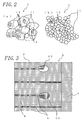
- Fig. 1 is a perspective view showing an example of a multi-layer piezoelectric element according to an embodiment of the invention
- Figs. 2(a) and 2(b) are schematic views of a polarization domain of a piezoelectric layer which constitutes the multi-layer piezoelectric element shown in Fig. 1 , respectively.
- the multi-layer piezoelectric element 1 of the present embodiment comprises a stacked body 7 in which piezoelectric layers 3 and internal electrode layers 5 are alternately laminated, and an external electrode 9 which is joined to a side face of the stacked body 7 and is electrically connected to the internal electrode layers 5.
- the piezoelectric layers 3 comprise a polarization domain 12 extending over a plurality of crystal particles 11.
- a domain structure is realized by reducing discontinuity such as crystal defects at a particle boundary, residual stress, or a hetero-phase component. Therefore, in the piezoelectric layers 3 having such a domain structure, the force of constraint at the particle boundary of a domain wall decreases, and the moving speed of the domain wall with respect to the electric field applied to the piezoelectric layer 3 becomes high. That is, the response speed of displacement can be made high.
- the polarization domain 12 extending over the plurality of crystal particles 11 is formed in a part of the piezoelectric layers 3 located between the internal electrode layers 5.
- the size of the polarization domain 12 extending over the plurality of crystal particles 11 is greater than the thickness of a particle boundary layer whose minimum thickness is equal to or less than 1 nm, the size is not be limited to the particle size of the crystal particles 11.
- the part of the polarization domain 12 which is present over the plurality of crystal particles 11 may be anywhere of the domain which is located between the internal electrode layers 5, it is preferable that the polarization domain is mainly present at a central portion between the internal electrode layers 5 where the influence of stress between the internal electrode layer 5 and a porcelain of the piezoelectric layer 3 decreases.
- the polarization domain 12 extending over such a plurality of crystal particles 11 can be formed by firing the piezoelectric layer 3 at a low temperature. That is, crystal particle groups which are uniform in crystal arrangement are bonded and become one particle at a high firing temperature. In contrast, at a low firing temperature, it is possible to terminate sintering while a plane defect is left in the crystal group which is uniform in crystal arrangement, and a region where spontaneous polarization is uniform between adjacent particles can be created via the plane defect.
- a preferable peak temperature during firing is 850 to 950°C.
- temperature lowering it is preferable to apply a wind to an upper portion of a firing bowl and cool the bowl, from the viewpoint of growing up a polarization domain. That is, by cooling the bowl while sending a wind to the upper portion of the firing bowl, a temperature can be slowly lowered in a state where a temperature gradient is given to the piezoelectric element. Thereby, spontaneous polarization can be generated sequentially from a part of the piezoelectric element which falls below the Curie temperature, and a polarization domain straddled between crystal particles is easily formed.
- the polarization domain 12 extends over the plurality of crystal particles 11 with the plurality of crystal particles 11 located therein. Even in this state, a domain structure realized by reducing the discontinuity of a particle boundary is provided. However, in a case where the polarization domain 12 extending over the plurality of crystal particles 11 with the plurality of crystal particles 11 located therein in this way is present, the movement of the domain wall with respect to the electric field applied to the piezoelectric layer 3 becomes larger, and the amount of displacement of the piezoelectric layers 3 can be further increased.
- the size of the polarization domain 12 in this case is not particularly limited, and may be a size including the plurality of crystal particles 11.
- the piezoelectric layer 3 may be manufactured by low-temperature firing on the basis of fine power PZT (lead zirconate titanate). That is, the polarization domain 12 extending over the plurality of crystal particles 11 with a small crystal particle size can be formed by manufacturing the piezoelectric layer 3 by low-temperature firing on the basis of fine powder PZT. At this time, as a firing temperature, it is preferable that the peak temperature is set to 900°C or lower.
- the polarization domain 12 which straddles the plurality of crystal particles 11, it is necessary to suppress occurrence of discontinuity between the crystal particles 11.
- silver tends to selectively enter a particle boundary portion during firing.
- Low-temperature firing is important also from the viewpoints of reducing the amount of diffusion of the silver from the internal electrode to the particle boundary portion, and suppressing occurrence of discontinuity between the crystal particles 11.
- PZT in which a lead site is lost is used for the piezoelectric layer 3
- there is an effect that the silver diffused from the internal electrode during firing is incorporated into the lead site within a crystal particle. This effect is important in that the amount of the silver which is present at the particle boundary portion is suppressed.
- a direction of the spontaneous polarization of the polarization domain 12 is deviated from an electric field direction of a voltage applied between the internal electrode layers 5.
- Most of the displacement of the multi-layer piezoelectric element 1 is developed by aligning the direction of the spontaneous polarization of the polarization domain 12 with the electric field direction of a voltage applied to the piezoelectric layer 3. Accordingly, when the polarization domain 12 where the direction of spontaneous polarization has been deviated from the electric field direction of a voltage to be applied is present, the amount of displacement can be further increased.
- the direction of the deviation therefrom is not particularly limited, and may be various directions.
- a crystal phase used for the piezoelectric layer 3 contains a rhombohedral phase at least at a room temperature.
- the crystal orientation which can be a polarization axis is eight directions, compared to the six directions of a tetragonal phase.
- the piezoelectric body of the piezoelectric layer 3 is made of a soft material in which a donor is included in PZT. The reason is that since the soft material allows a domain wall to move easily, deformation of the piezoelectric layer occurs under a high load before polarization, and the orientation of the spontaneous polarization is easily aligned.
- PZT having the Curie temperature higher than a room temperature may be selected as PZT used for the piezoelectric layer 3.
- PZT whose Curie temperature is 300°C or higher is selected from a viewpoint that the polarization domain 12 is stabilized with respect to temperature.
- an average particle size of the plurality of crystal particles 11 of the piezoelectric layers 3 is 5 ⁇ m or less. If the average particle size of the plurality of crystal particles 11 is 5 ⁇ m or more, transgranular fracture tends to occur. On the other hand, if the average particle size is 5 ⁇ m or less, the fracture mode of the piezoelectric layer 3 by driving tends to become intergranular fracture. As a result, since the porcelain strength of the piezoelectric layers 3 is high, and a crack is hard to grow, deterioration of the displacement caused by continuous driving tends to be almost eliminated. On the other hand, when the average particle size of the plurality of crystal particles 11 is greater than 5 ⁇ m, deterioration of characteristics caused by continuous driving tends to increase.
- a constituent element ratio which is a ratio of a constituent element of an A site and a constituent element of a B site of a PZT porcelain composition which constitutes the piezoelectric layer 3 may be set to 1 or less so as to form the piezoelectric layer 3.
- Fig. 3 is an enlarged sectional view of a main part schematically showing an example in the vicinity of the end of the internal electrode layers 5 in the stacked body 7 of the multi-layer piezoelectric element 1 shown in Fig. 1 .
- a part 13 in the vicinity of the end of the internal electrode layers 5 in the stacked body 7 of the multi-layer piezoelectric element 1 is located at the boundary between an active region and an inactive region in the stacked body 7, and when the polarization domain 12 exists in this part, this part 13 becomes softer as compared to the periphery.
- the amount of displacement of the multi-layer piezoelectric element 1 increases. That is, by arranging a region where the polarization domain 12 in which the force of constraint caused by the particle boundary of a domain wall decreases is present, in the vicinity of the end of the internal electrode layers 5, the amount of displacement of the multi-layer piezoelectric layer 1 increases.
- the proportion of Ag in the metal paste of the end of the internal electrode layers 5 to the central portion of the internal electrode layers 5 may be increased.
- the polarization domain 12 is formed in some of the piezoelectric layers 3. That is, since the piezoelectric layers 3 in which the polarization domain 12 extending over the plurality of crystal particles 11 is present have a large amount of displacement, the amount of displacement can be further increased by arranging some of such piezoelectric layers 3 in the stacked body 7.
- the proportion of silver (Ag) in the internal electrode layer 5 at a position where the presence of the polarization domain 12 is increased may be set to be as high as 95% by mass, and the proportion of silver in the other internal electrode layers 5 may be set to 90% by mass.
- the polarization domain 12 is formed in all of the piezoelectric layers 3. That is, since the piezoelectric layers 3 in which the polarization domain 12 extending over the plurality of crystal particles 11 is present have a large amount of displacement, the amount of displacement of the multi-layer piezoelectric element 1 increases further by forming such a polarization domain 12 in all of the piezoelectric layer 3.
- the polarization domain 12 extending over the plurality of crystal particles 11 is formed in all of the piezoelectric layers 3, the polarization domain may be basically formed by the same method as the aforementioned forming method. That is, in order to reduce the discontinuity of the interface between the crystal particles 11, it is necessary to reduce the residual stress generated at an interface between the internal electrode layer 5 and the porcelain of the piezoelectric layer 3, and to select a metal with a low Young's modulus for the internal electrode layer 5. Thus, in a case where an alloy of Ag and Pd is used, it is preferable that the proportion of Ag is set to 95% by mass or more, and the firing temperature is set to 900°C or lower. By doing in this way, discontinuity such as crystal defects at a particle boundary, residual stress, or a hetero-phase component, can be reduced, and the polarization domain 12 extending over the plurality of crystal particles 11 can be formed in all of the piezoelectric layers 3.
- a ceramic green sheet is prepared from this slurry by using tape molding methods such as a doctor blade method and a calendar roll method.
- the PZT powder it is preferable to use powder obtained by synthesizing a mixed raw material made of high purity powder at a low temperature of 700°C or lower by a solid phase technique.
- a piezoelectric ceramic material made mainly of barium titanate BaTiO 3 in addition to lead zirconate titanate (PZT) as a piezoelectric material may be used for the piezoelectric layer 3.
- PZT lead zirconate titanate
- this piezoelectric ceramic it is desirable that a ceramic material having piezoelectric strain constant d 33 exhibiting high piezoelectric characteristics is used.
- a metal paste for the internal electrode layers 5 is prepared.
- This metal paste is obtained by adding and mixing a binder, a plasticizer, and the like to metal powder made mainly of silver-palladium (Ag-Pd).
- This metal paste is coated on one side of the ceramic green sheet by screen printing or the like, thereby forming an internal electrode paste layer.
- the proportion of Pd in the metal paste be set to 10% by mass or less. Additionally, by using metal pastes whose proportions of Pd are different from each other depending on the position of the internal electrode layer 5 in the stacked body 7, it is possible to obtain a stacked body 7 including the piezoelectric layers 3 having the polarization domain 12 extending over the plurality of crystal particles 11 at a desired position in the stacked body 7.
- the proportion of Pd in the metal paste can be changed according to how the polarization domain 12 is formed.
- metal powder for the internal electrode layer 5 powder such as copper, palladium, platinum, or nickel in addition to silver palladium may be used.
- a stacked compact before firing is obtained by laminating and drying ceramic green sheets on which an internal electrode paste layer has been printed using metal paste so as to have, for example, a structure shown in Fig. 1 .
- ceramic green sheets on which the metal paste is not printed may be partially laminated in a part which needs thickness.
- the stacked compact can be cut with the size of the stacked body 7 as an individual piece, and can be formed in a desired shape.
- the thickness of the internal electrode paste layer can be set to about 1 to 40 ⁇ m, if screen printing is used, according to the thickness of the internal electrode layer 5.
- firing of the stacked compact is performed at 900 to 1000°C.
- the stacked compact is maintained for 25 hours or more in a temperature region of 650°C or higher after temperature is elevated.
- temperature is lowered over 15 hours or more within a temperature range from 650°C to 200°C.
- the obtained sintered compact is formed into the stacked body 7 after being worked with desired dimensions, and external electrodes 9 are formed on side faces of the stacked body.
- the external electrodes 9 can be formed by preparing metal paste by adding and mixing a binder, a plasticizer, glass powder, and the like to a metal powder made mainly of silver, and printing this metal paste on the side faces of the stacked body 7 by screen printing or the like, and firing the metal paste at a temperature of 600 to 800°C.
- the external surface of the external electrode 9 may be formed with a conductive auxiliary member made of a conductive adhesive in which a metal mesh or a mesh-like metal plate is buried.
- the metal mesh is one formed by knitting a metal wire
- the mesh-like metal plate is one formed with holes in the shape of a mesh in a metal plate.
- sheathing resin made of silicone rubber or the like may be coated on the side faces of the stacked body 7 including the external electrode 9, using technique such as dipping, after a lead wire is connected to the external electrode 9 with solder or the like.
- the piezoelectric layers 3 comprise the polarization domain 12 extending over the plurality of crystal particles 11.
- PZT powder obtained by synthesizing a mixed raw material made of high purity powder at a low temperature of 700°C or lower by the solid phase technique is used as the PZT powder for forming the piezoelectric layer 3, and a metal paste in which the proportion of Pd is set to 10% by mass or less is used as the metal paste for the internal electrode layer 5.
- the peak temperature is within a range of 900°C to 1000°C
- the stacked compact is maintained for 25 hours or more in a temperature region of 650°C or higher, and temperature is lowered over 15 hours or more within a temperature range from 650°C to 200°C in a temperature lowering process.
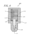
- Fig. 4 is a schematic sectional view showing an example of an injection device according to an embodiment of the invention.
- the injection device 19 of the present embodiment comprises a housing container (container) 23 having an injection nozzle 21 at one end thereof and the multi-layer piezoelectric element 1 represented by the example of the above embodiment, configured to be housed inside the housing container 23.
- a needle valve 25 capable of opening and closing the injection nozzle 21 is disposed within the housing container 23.
- a fluid passage 27 is disposed in the injection nozzle 21 so as to be capable of communicating with the injection nozzle 21 according to the movement of the needle valve 25.
- the fluid passage 27 is connected to an external fluid supply source from which a fluid is supplied to the fluid passage 27 always at a high pressure. Accordingly, when the needle valve 25 opens the injection nozzle 21, the fuel which has been supplied to the fluid passage 27 is injected to the outside, for example, a combustion chamber (not shown) of an internal combustion engine or the like, through the injection nozzle 21.
- the upper end of the needle valve 25 has a larger internal diameter, and has arranged therein a cylinder 29 formed in the housing container 23 and a piston 31 slidable on the cylinder 29. Then, the multi-layer piezoelectric element 1 of the invention as mentioned above is housed in the housing container 23.
- the injection device 19 of the invention includes a container having the injection nozzle 21, and the multi-layer piezoelectric element 1 of the invention, and may be constructed so that a fluid filled into the container is configured to be injected through the injection nozzle 21 by driving the multi-layer piezoelectric element 1. That is, the multi-layer piezoelectric element 1 is not necessarily housed inside the container, and may be constructed so that the pressure for controlling the injection of the fluid is applied to the inside of the container by driving the multi-layer piezoelectric element 1.
- various liquid fluids (conductive paste or the like) other than fuel or ink, and gases are included in the fluid.
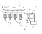
- Fig. 5 is a schematic view showing an example of a fuel injection system according to an embodiment of the invention.
- the fuel injection system 35 of the present embodiment includes a common rail 37 configured to store high-pressure fuel as a high-pressure fluid, a plurality of the injection devices 19 of the invention configured to inject the high-pressure fluid stored in the common rail 37, a pressure pump 39 configured to supply the high-pressure fluid to the common rail 37, and an injection control unit 41 configured to send a driving signal to the injection device 19.
- the injection control unit 41 controls the amount and timing of injection of the high-pressure fluid on the basis of external information or a signal from the outside. For example, the injection control unit controls the amount and timing of fuel injection while sensing the situation of an internal combustion chamber of the engine by a sensor or the like.
- the pressure pump 39 plays the role to supply fuel into the common rail 37 from the fuel tank 43 at a high pressure of about 1000 to 2000 atmospheres, and preferably about 1500 to 1700 atmospheres.
- the high-pressure fuel sent from the pressure pump 39 is stored and appropriately fed into the injection device 19.
- the injection device 19 injects a predetermined amount of high-pressure fuel in the form of a mist to the outside or an adjacent container, for example, into an internal combustion chamber of an engine through the injection nozzle 21 as mentioned above.
- a piezoelectric actuator including the multi-layer piezoelectric element of the invention was manufactured for trial as follows.
- a slurry was prepared which was obtained by mixing calcined powder of piezoelectric ceramics made mainly of lead zirconate titanate (PZT) with an average particle size of 0.4 ⁇ m, a binder, and a plasticizer.
- a ceramic green sheet which becomes a piezoelectric layer with a thickness of about 150 ⁇ m after firing was prepared using this slurry by a doctor blade method.
- a binder was added to a silver-palladium alloy (silver 70% by mass and palladium 30% by mass), thereby preparing a metal paste for an internal electrode layer.
- This metal paste was screen-printed on one side of the ceramic green sheet, and such ceramic green sheets on which the metal paste was printed were laminated as many as 300 sheets. Firing of this stacked compact was performed by maintaining the stacked compact for 200 minutes at the peak temperature of 1100°C and then lowering temperature to the room temperature over 15 hours. The obtained sintered compact was worked with predetermined dimensions to obtain a stacked body.
- a ceramic green sheet was obtained similarly to Sample No. 1.
- two kinds of metal pastes were prepared using two kinds of metals for an internal electrode layer.
- One metal paste is a metal paste using an alloy of silver of 90% by mass and palladium of 10% by mass
- another metal paste is a metal paste of silver of 100%.
- the metal paste using the alloy of silver of 90% by mass and palladium of 10% by mass was screen-printed on one side of the ceramic green sheet.
- the metal paste of silver of 100% was overlappingly screen-printed at a position which becomes an electrode end when a stacked body is obtained, such ceramic green sheets were laminated as many as 300 layers to obtain a stacked compact.
- Firing of this stacked compact was performed by elevating temperature over 10 hours from 650°C to 900°C, then maintaining the stacked compact for 5 hours at 900°C, lowering temperature to 650°C over 10 hours, and lowering temperature to 200°C over 15 hours.
- the obtained sintered compact was worked with predetermined dimensions to obtain a stacked body.
- the stress at an interface between the internal electrode layer and the piezoelectric layer in the vicinity of the end of the internal electrode layers in the prepared stacked body can be reduced by printing the metal paste of silver of 100% at a position which becomes the end of the internal electrode layer with respect to the central portion of the internal electrode layers when being laminated.
- the residual stress which is present at a particle boundary in the vicinity of the end of the internal electrode layer was reduced, and the polarization domain extending over the plurality of crystal particles was easily formed.
- a ceramic green sheet was obtained similarly to Sample No. 1.
- two kinds of metal pastes were prepared using two kinds of metals for an internal electrode layer.
- One metal paste is a metal paste using an alloy of silver of 90% by mass and palladium of 10% by mass
- another metal paste is a metal paste using the alloy of silver of 95% by mass and palladium of 5% by mass.
- the prepared metal pastes were screen-printed on one side of the ceramic green sheets, respectively.
- the stress at an interface between the internal electrode layer and the piezoelectric layer can be reduced at the central portion of the stacked body by printing the metal paste of silver of 95% by mass for the internal electrode layer on the ceramic green sheet which becomes a central portion of the stacked body when being laminated.
- the residual stress which is present at a particle boundary in the vicinity of the laminating central portion of the stacked body was reduced, and the polarization domain extending over the plurality of crystal particles was easily formed.
- a ceramic green sheet was obtained similarly to Sample No. 1.
- the metal paste using the alloy of silver of 95% by mass and palladium of 5% by mass was prepared for an internal electrode layer.
- the prepared metal paste was screen-printed on one side of the ceramic green sheet, and then a stacked compact of 300 layers was obtained. Firing of this stacked compact was performed by elevating the temperature over 10 hours from 650°C to 900°C, then maintaining the stacked compact for 5 hours at 900°C, lowering temperature to 650°C over 10 hours, and lowering temperature to 200°C over 15 hours.
- the obtained sintered compact was worked with predetermined dimensions to obtain a stacked body.
- the firing peak temperature By setting the firing peak temperature to 900°C in this way, thereby performing firing while suppressing decomposition of lead, the composition of the piezoelectric layer is prevented from becoming uneven. Additionally, by selecting a metal with a high proportion of Ag and a low Young's modulus as the internal electrode layer, discontinuity such as crystal defects at a particle boundary, residual stress, or a hetero-phase component, was reduced, and the polarization domain extending over the plurality of crystal particles was easily formed in all of the piezoelectric layers.
- An external electrode was formed on a stacked body of each of the above Sample Nos. 1 to 4. Thereafter, polarization treatment was performed on each multi-layer piezoelectric element by applying a direct-current electric field of 3 kV/mm to the external electrode for 15 minutes via a conductive member. Multi-layer piezoelectric elements serving as piezoelectric actuators were prepared in this way.
- the state of a polarization domain was observed by the TEM (transmission electron microscope).
- the presence of the polarization domain extending over a plurality of crystal particles could be confirmed in some of the piezoelectric layers at the laminating central portion of the stacked body.
- the average particle size of the plurality of crystal particles of the piezoelectric layers of the multi-layer piezoelectric element of Sample No. 1 which is a comparative example was 6 ⁇ m, and cracks were frequently generated in the piezoelectric layer which is porcelain after continuous driving, whereas in the multi-layer piezoelectric elements of Sample Nos. 2 to 4 which are examples of the invention, the average particle size of the plurality of crystal particles of the piezoelectric layer was 2 to 3 ⁇ m, and few small cracks were only observed, and durability was also excellent even after continuous driving.
- the initial amount of displacement was 24 ⁇ m, while the amount of displacement after 1 ⁇ 10 7 times decreased to 18 ⁇ m, and cracks were frequently generated, and the measurement was stopped in the piezoelectric layer after 5 ⁇ 10 7 times.
- the initial amount of displacement was 36 ⁇ m, while the amount of displacement after 1 ⁇ 10 7 times was 36 ⁇ m, the amount of displacement after 1 ⁇ 10 8 times was 35 ⁇ m, and the amount of displacement after 1 ⁇ 10 9 times was 35 ⁇ m.
- the initial amount of displacement was 41 ⁇ m, while the amount of displacement after 1 ⁇ 10 7 times was 40 ⁇ m, the amount of displacement after 1 ⁇ 10 8 times was 40 ⁇ m, and the amount of displacement after 1 ⁇ 10 9 times was 39 ⁇ m.
- the initial amount of displacement was 48 ⁇ m, while the amount of displacement after 1 ⁇ 10 7 times was 47 ⁇ m, the amount of displacement after 1 ⁇ 10 8 times was 47 ⁇ m, and the amount of displacement after 1 ⁇ 10 9 times was also 47 ⁇ m. It can be seen from these results that, according to the multi-layer piezoelectric elements of the invention, a large amount of displacement is given, the performance of the elements does not deteriorate greatly even after continuous driving of 1 ⁇ 10 9 times, and prolonged durability is excellent.
Applications Claiming Priority (2)
| Application Number | Priority Date | Filing Date | Title |
|---|---|---|---|
| JP2008219240 | 2008-08-28 | ||
| PCT/JP2009/064837 WO2010024277A1 (ja) | 2008-08-28 | 2009-08-26 | 積層型圧電素子および噴射装置ならびに燃料噴射システム |
Publications (3)
| Publication Number | Publication Date |
|---|---|
| EP2337104A1 true EP2337104A1 (de) | 2011-06-22 |
| EP2337104A4 EP2337104A4 (de) | 2013-05-29 |
| EP2337104B1 EP2337104B1 (de) | 2014-08-06 |
Family
ID=41721444
Family Applications (1)
| Application Number | Title | Priority Date | Filing Date |
|---|---|---|---|
| EP09809928.6A Active EP2337104B1 (de) | 2008-08-28 | 2009-08-26 | Mehrschichtiges piezoelektrisches element, injektor und brennstoffeinspritzsystem |
Country Status (5)
| Country | Link |
|---|---|
| US (1) | US8757130B2 (de) |
| EP (1) | EP2337104B1 (de) |
| JP (1) | JP5341094B2 (de) |
| CN (1) | CN102132433B (de) |
| WO (1) | WO2010024277A1 (de) |
Cited By (1)
| Publication number | Priority date | Publication date | Assignee | Title |
|---|---|---|---|---|
| WO2012123156A1 (de) * | 2011-03-17 | 2012-09-20 | Epcos Ag | Piezoelektrisches aktorbauelement und verfahren zur herstellung eines piezoelektrischen aktorbauelements |
Families Citing this family (17)
| Publication number | Priority date | Publication date | Assignee | Title |
|---|---|---|---|---|
| JP2011510505A (ja) | 2008-01-23 | 2011-03-31 | エプコス アクチエンゲゼルシャフト | 圧電多層構成要素 |
| EP2245679B1 (de) | 2008-01-23 | 2015-07-29 | Epcos AG | Piezoelektrisches vielschichtbauelement |
| JP5339885B2 (ja) * | 2008-12-22 | 2013-11-13 | 京セラ株式会社 | 積層型圧電素子、これを備えた噴射装置および燃料噴射システム |
| EP2495776B1 (de) * | 2009-10-28 | 2015-03-18 | Kyocera Corporation | Mehrschichtiges piezoelektrisches element sowie damit verwendete einspritzvorrichtung und brennstoffeinspritzsystem |
| FR2959877B1 (fr) * | 2010-05-06 | 2013-06-14 | Renault Sa | Procede de fabrication d'un actionneur a empilement de couches alternees d'electrode intercalaire et de materiau piezoelectrique |
| JP2011249659A (ja) * | 2010-05-28 | 2011-12-08 | Kyocera Corp | 圧電素子、これを備えた噴射装置及び燃料噴射システム |
| JP5697381B2 (ja) * | 2010-08-30 | 2015-04-08 | 京セラ株式会社 | 積層型圧電素子およびこれを備えた噴射装置ならびに燃料噴射システム |
| JP5456179B2 (ja) * | 2011-01-21 | 2014-03-26 | 京セラ株式会社 | 積層型圧電素子およびこれを備えた圧電アクチュエータ、噴射装置ならびに燃料噴射システム |
| US20140084754A1 (en) * | 2012-09-21 | 2014-03-27 | Tdk Corporation | Thin film piezoelectric device |
| US10532124B2 (en) * | 2012-12-27 | 2020-01-14 | Kimberly-Clark Worldwide, Inc. | Water soluble farnesol analogs and their use |
| JP5611427B2 (ja) * | 2013-07-31 | 2014-10-22 | 京セラ株式会社 | 積層型圧電素子、これを備えた噴射装置および燃料噴射システム |
| JP6270505B2 (ja) * | 2014-01-27 | 2018-01-31 | オリンパス株式会社 | 積層型超音波振動デバイス、積層型超音波振動デバイスの製造方法および超音波医療装置 |
| JP6381246B2 (ja) * | 2014-03-25 | 2018-08-29 | 日本特殊陶業株式会社 | 圧電素子およびその製造方法 |
| TWI624969B (zh) * | 2015-10-09 | 2018-05-21 | Ngk Spark Plug Co Ltd | Piezoelectric element, piezoelectric actuator and piezoelectric transformer |
| US9786831B1 (en) * | 2016-01-27 | 2017-10-10 | Magnecomp Corporation | Suspension having a stacked D33 mode PZT actuator with constraint layer |
| KR102523255B1 (ko) * | 2019-06-28 | 2023-04-19 | 가부시키가이샤 무라타 세이사쿠쇼 | 적층형 전자부품 |
| JP7406952B2 (ja) * | 2019-10-17 | 2023-12-28 | 太陽誘電株式会社 | 圧電セラミックス及びその製造方法、並びに圧電素子 |
Citations (2)
| Publication number | Priority date | Publication date | Assignee | Title |
|---|---|---|---|---|
| JP2005123554A (ja) * | 2003-09-26 | 2005-05-12 | Murata Mfg Co Ltd | 積層型圧電素子とその製造方法 |
| US20080036334A1 (en) * | 2004-10-01 | 2008-02-14 | Murata Manufacturing Co., Ltd. | Piezoelectric ceramic composition and piezoelectric ceramic electronic component |
Family Cites Families (16)
| Publication number | Priority date | Publication date | Assignee | Title |
|---|---|---|---|---|
| JPS5854689A (ja) * | 1981-09-28 | 1983-03-31 | Hitachi Ltd | チタン酸鉛系圧電磁器の製造方法 |
| JPS63102384A (ja) * | 1986-10-20 | 1988-05-07 | Fuji Electric Co Ltd | 積層圧電アクチュエ−タ素子 |
| JP2825366B2 (ja) * | 1991-05-23 | 1998-11-18 | 松下電器産業株式会社 | 圧電セラミックス |
| JP3399785B2 (ja) * | 1997-05-27 | 2003-04-21 | 富士通株式会社 | 圧電体装置及びその製造方法 |
| JP3520403B2 (ja) * | 1998-01-23 | 2004-04-19 | セイコーエプソン株式会社 | 圧電体薄膜素子、アクチュエータ、インクジェット式記録ヘッド、及びインクジェット式記録装置 |
| JP2000214065A (ja) | 1999-01-25 | 2000-08-04 | Sony Corp | 強誘電体薄膜の特性解析方法 |
| JP2004221411A (ja) | 2003-01-16 | 2004-08-05 | Fujitsu Ltd | 素子評価方法 |
| JP4535721B2 (ja) * | 2003-11-26 | 2010-09-01 | 京セラ株式会社 | 圧電磁器および積層型圧電素子並びに噴射装置 |
| US20070125977A1 (en) * | 2003-11-26 | 2007-06-07 | Tomohiro Kawamoto | Piezoelectric ceramic and laminated piezoelectric element |
| JP4373777B2 (ja) * | 2003-12-26 | 2009-11-25 | 敏夫 小川 | 圧電デバイス |
| JP2007153631A (ja) | 2005-11-30 | 2007-06-21 | Tdk Corp | 誘電体磁器組成物、電子部品および積層セラミックコンデンサ |
| CN101507007B (zh) * | 2006-09-28 | 2010-11-17 | 京瓷株式会社 | 层叠型压电元件、使用它的喷射装置和燃料喷射系统、层叠型压电元件的制造方法 |
| JP2008218620A (ja) | 2007-03-02 | 2008-09-18 | Matsushita Electric Ind Co Ltd | 圧電体薄膜素子、圧電体薄膜素子の製造方法、インクジェットヘッド、およびインクジェット式記録装置 |
| EP1953840A3 (de) * | 2007-01-31 | 2012-04-11 | Panasonic Corporation | Piezoelektrische Dünnfilmvorrichtung und Verfahren zur Herstellung einer piezoelektrischen Dünnfilmvorrichtung und Tintenstrahlkopf und Tintenstrahlaufzeichnungsvorrichtung |
| JP5090466B2 (ja) * | 2007-11-28 | 2012-12-05 | 京セラ株式会社 | 積層型圧電素子、これを備えた噴射装置及び燃料噴射システム |
| WO2010013670A1 (ja) * | 2008-07-29 | 2010-02-04 | 京セラ株式会社 | 積層型圧電素子およびこれを用いた噴射装置ならびに燃料噴射システム |
-
2009
- 2009-08-26 WO PCT/JP2009/064837 patent/WO2010024277A1/ja active Application Filing
- 2009-08-26 JP JP2010526732A patent/JP5341094B2/ja active Active
- 2009-08-26 CN CN2009801335832A patent/CN102132433B/zh active Active
- 2009-08-26 EP EP09809928.6A patent/EP2337104B1/de active Active
- 2009-08-26 US US13/061,486 patent/US8757130B2/en active Active
Patent Citations (2)
| Publication number | Priority date | Publication date | Assignee | Title |
|---|---|---|---|---|
| JP2005123554A (ja) * | 2003-09-26 | 2005-05-12 | Murata Mfg Co Ltd | 積層型圧電素子とその製造方法 |
| US20080036334A1 (en) * | 2004-10-01 | 2008-02-14 | Murata Manufacturing Co., Ltd. | Piezoelectric ceramic composition and piezoelectric ceramic electronic component |
Non-Patent Citations (2)
| Title |
|---|
| JONES JACOB ET AL: "Domain texture distributions in tetragonal lead zirconate titanate by x-ray and neutron diffraction", JOURNAL OF APPLIED PHYSICS, AMERICAN INSTITUTE OF PHYSICS. NEW YORK, US, vol. 97, no. 3, 19 January 2005 (2005-01-19), pages 34113-034113, XP012070609, ISSN: 0021-8979 * |
| See also references of WO2010024277A1 * |
Cited By (1)
| Publication number | Priority date | Publication date | Assignee | Title |
|---|---|---|---|---|
| WO2012123156A1 (de) * | 2011-03-17 | 2012-09-20 | Epcos Ag | Piezoelektrisches aktorbauelement und verfahren zur herstellung eines piezoelektrischen aktorbauelements |
Also Published As
| Publication number | Publication date |
|---|---|
| US8757130B2 (en) | 2014-06-24 |
| US20110180623A1 (en) | 2011-07-28 |
| EP2337104B1 (de) | 2014-08-06 |
| CN102132433A (zh) | 2011-07-20 |
| JPWO2010024277A1 (ja) | 2012-01-26 |
| JP5341094B2 (ja) | 2013-11-13 |
| EP2337104A4 (de) | 2013-05-29 |
| WO2010024277A1 (ja) | 2010-03-04 |
| CN102132433B (zh) | 2013-11-06 |
Similar Documents
| Publication | Publication Date | Title |
|---|---|---|
| EP2337104B1 (de) | Mehrschichtiges piezoelektrisches element, injektor und brennstoffeinspritzsystem | |
| US20100066211A1 (en) | Multi-Layer Electronic Component and Method for Manufacturing the Same, Multi-Layer Piezoelectric Element | |
| EP2461385B1 (de) | Piezoelektrisches vielschichtbauelement sowie injektor und brennstoffeinspritzsystem mit diesem | |
| JP4933554B2 (ja) | 積層型圧電素子、これを用いた噴射装置及び燃料噴射システム、並びに積層型圧電素子の製造方法 | |
| JP5084744B2 (ja) | 積層型圧電素子、これを備えた噴射装置及び燃料噴射システム | |
| EP2237337A1 (de) | Laminiertes piezoelektrisches element und einspritzeinrichtung und kraftstoffeinspritzsystem damit | |
| EP2495776B1 (de) | Mehrschichtiges piezoelektrisches element sowie damit verwendete einspritzvorrichtung und brennstoffeinspritzsystem | |
| WO2007037377A1 (ja) | 積層型圧電素子およびこれを用いた噴射装置 | |
| EP2337103A1 (de) | Mehrschichtiges piezoelektrisches element, injektor damit und brennstoffeinspritzsystem | |
| EP1686633A1 (de) | Mehrschichtiges piezoelektrisches bauelement | |
| JP2005285883A (ja) | 積層型圧電素子およびその製造方法ならびにこれを用いた噴射装置 | |
| JP2003101092A (ja) | 積層型圧電素子及びその製法並びに噴射装置 | |
| EP2333858A1 (de) | Laminiertes piezoelektrisches element und einspritzeinrichtung und kraftstoffeinspritzsystem mit einem laminierten piezoelektrischen element | |
| JP4925563B2 (ja) | 積層型圧電素子およびこれを用いた噴射装置 | |
| WO2012011302A1 (ja) | 積層型圧電素子およびこれを備えた噴射装置ならびに燃料噴射システム | |
| JP4868707B2 (ja) | 積層型圧電素子および噴射装置 | |
| JP4822664B2 (ja) | 積層型圧電素子およびその製法、並びに噴射装置 | |
| JP4873837B2 (ja) | 積層型圧電素子および噴射装置 | |
| JP5449433B2 (ja) | 積層型圧電素子およびこれを用いた噴射装置 | |
| JP2011109119A (ja) | 積層型圧電素子およびこれを用いた噴射装置 | |
| JPWO2009107700A1 (ja) | 積層型圧電素子、これを備えた噴射装置及び燃料噴射システム |
Legal Events
| Date | Code | Title | Description |
|---|---|---|---|
| PUAI | Public reference made under article 153(3) epc to a published international application that has entered the european phase |
Free format text: ORIGINAL CODE: 0009012 |
|
| 17P | Request for examination filed |
Effective date: 20110328 |
|
| AK | Designated contracting states |
Kind code of ref document: A1 Designated state(s): AT BE BG CH CY CZ DE DK EE ES FI FR GB GR HR HU IE IS IT LI LT LU LV MC MK MT NL NO PL PT RO SE SI SK SM TR |
|
| AX | Request for extension of the european patent |
Extension state: AL BA RS |
|
| DAX | Request for extension of the european patent (deleted) | ||
| A4 | Supplementary search report drawn up and despatched |
Effective date: 20130426 |
|
| RIC1 | Information provided on ipc code assigned before grant |
Ipc: F02M 51/06 20060101ALI20130422BHEP Ipc: H01L 41/273 20130101ALI20130422BHEP Ipc: H01L 41/187 20060101ALI20130422BHEP Ipc: H01L 41/083 20060101AFI20130422BHEP Ipc: F02M 51/00 20060101ALI20130422BHEP |
|
| GRAP | Despatch of communication of intention to grant a patent |
Free format text: ORIGINAL CODE: EPIDOSNIGR1 |
|
| INTG | Intention to grant announced |
Effective date: 20140224 |
|
| GRAS | Grant fee paid |
Free format text: ORIGINAL CODE: EPIDOSNIGR3 |
|
| GRAA | (expected) grant |
Free format text: ORIGINAL CODE: 0009210 |
|
| AK | Designated contracting states |
Kind code of ref document: B1 Designated state(s): AT BE BG CH CY CZ DE DK EE ES FI FR GB GR HR HU IE IS IT LI LT LU LV MC MK MT NL NO PL PT RO SE SI SK SM TR |
|
| REG | Reference to a national code |
Ref country code: GB Ref legal event code: FG4D |
|
| REG | Reference to a national code |
Ref country code: AT Ref legal event code: REF Ref document number: 681380 Country of ref document: AT Kind code of ref document: T Effective date: 20140815 Ref country code: CH Ref legal event code: EP |
|
| REG | Reference to a national code |
Ref country code: IE Ref legal event code: FG4D |
|
| REG | Reference to a national code |
Ref country code: DE Ref legal event code: R096 Ref document number: 602009025847 Country of ref document: DE Effective date: 20140918 |
|
| REG | Reference to a national code |
Ref country code: AT Ref legal event code: MK05 Ref document number: 681380 Country of ref document: AT Kind code of ref document: T Effective date: 20140806 |
|
| REG | Reference to a national code |
Ref country code: NL Ref legal event code: VDEP Effective date: 20140806 |
|
| REG | Reference to a national code |
Ref country code: LT Ref legal event code: MG4D |
|
| PG25 | Lapsed in a contracting state [announced via postgrant information from national office to epo] |
Ref country code: PT Free format text: LAPSE BECAUSE OF FAILURE TO SUBMIT A TRANSLATION OF THE DESCRIPTION OR TO PAY THE FEE WITHIN THE PRESCRIBED TIME-LIMIT Effective date: 20141209 Ref country code: NO Free format text: LAPSE BECAUSE OF FAILURE TO SUBMIT A TRANSLATION OF THE DESCRIPTION OR TO PAY THE FEE WITHIN THE PRESCRIBED TIME-LIMIT Effective date: 20141106 Ref country code: GR Free format text: LAPSE BECAUSE OF FAILURE TO SUBMIT A TRANSLATION OF THE DESCRIPTION OR TO PAY THE FEE WITHIN THE PRESCRIBED TIME-LIMIT Effective date: 20141107 Ref country code: BG Free format text: LAPSE BECAUSE OF FAILURE TO SUBMIT A TRANSLATION OF THE DESCRIPTION OR TO PAY THE FEE WITHIN THE PRESCRIBED TIME-LIMIT Effective date: 20141106 Ref country code: LT Free format text: LAPSE BECAUSE OF FAILURE TO SUBMIT A TRANSLATION OF THE DESCRIPTION OR TO PAY THE FEE WITHIN THE PRESCRIBED TIME-LIMIT Effective date: 20140806 Ref country code: ES Free format text: LAPSE BECAUSE OF FAILURE TO SUBMIT A TRANSLATION OF THE DESCRIPTION OR TO PAY THE FEE WITHIN THE PRESCRIBED TIME-LIMIT Effective date: 20140806 Ref country code: SE Free format text: LAPSE BECAUSE OF FAILURE TO SUBMIT A TRANSLATION OF THE DESCRIPTION OR TO PAY THE FEE WITHIN THE PRESCRIBED TIME-LIMIT Effective date: 20140806 Ref country code: FI Free format text: LAPSE BECAUSE OF FAILURE TO SUBMIT A TRANSLATION OF THE DESCRIPTION OR TO PAY THE FEE WITHIN THE PRESCRIBED TIME-LIMIT Effective date: 20140806 |
|
| PG25 | Lapsed in a contracting state [announced via postgrant information from national office to epo] |
Ref country code: LV Free format text: LAPSE BECAUSE OF FAILURE TO SUBMIT A TRANSLATION OF THE DESCRIPTION OR TO PAY THE FEE WITHIN THE PRESCRIBED TIME-LIMIT Effective date: 20140806 Ref country code: CY Free format text: LAPSE BECAUSE OF FAILURE TO SUBMIT A TRANSLATION OF THE DESCRIPTION OR TO PAY THE FEE WITHIN THE PRESCRIBED TIME-LIMIT Effective date: 20140806 Ref country code: PL Free format text: LAPSE BECAUSE OF FAILURE TO SUBMIT A TRANSLATION OF THE DESCRIPTION OR TO PAY THE FEE WITHIN THE PRESCRIBED TIME-LIMIT Effective date: 20140806 Ref country code: HR Free format text: LAPSE BECAUSE OF FAILURE TO SUBMIT A TRANSLATION OF THE DESCRIPTION OR TO PAY THE FEE WITHIN THE PRESCRIBED TIME-LIMIT Effective date: 20140806 Ref country code: NL Free format text: LAPSE BECAUSE OF FAILURE TO SUBMIT A TRANSLATION OF THE DESCRIPTION OR TO PAY THE FEE WITHIN THE PRESCRIBED TIME-LIMIT Effective date: 20140806 Ref country code: IS Free format text: LAPSE BECAUSE OF FAILURE TO SUBMIT A TRANSLATION OF THE DESCRIPTION OR TO PAY THE FEE WITHIN THE PRESCRIBED TIME-LIMIT Effective date: 20141206 Ref country code: AT Free format text: LAPSE BECAUSE OF FAILURE TO SUBMIT A TRANSLATION OF THE DESCRIPTION OR TO PAY THE FEE WITHIN THE PRESCRIBED TIME-LIMIT Effective date: 20140806 |
|
| REG | Reference to a national code |
Ref country code: CH Ref legal event code: PL |
|
| PG25 | Lapsed in a contracting state [announced via postgrant information from national office to epo] |
Ref country code: CH Free format text: LAPSE BECAUSE OF NON-PAYMENT OF DUE FEES Effective date: 20140831 Ref country code: CZ Free format text: LAPSE BECAUSE OF FAILURE TO SUBMIT A TRANSLATION OF THE DESCRIPTION OR TO PAY THE FEE WITHIN THE PRESCRIBED TIME-LIMIT Effective date: 20140806 Ref country code: BE Free format text: LAPSE BECAUSE OF NON-PAYMENT OF DUE FEES Effective date: 20140831 Ref country code: EE Free format text: LAPSE BECAUSE OF FAILURE TO SUBMIT A TRANSLATION OF THE DESCRIPTION OR TO PAY THE FEE WITHIN THE PRESCRIBED TIME-LIMIT Effective date: 20140806 Ref country code: RO Free format text: LAPSE BECAUSE OF FAILURE TO SUBMIT A TRANSLATION OF THE DESCRIPTION OR TO PAY THE FEE WITHIN THE PRESCRIBED TIME-LIMIT Effective date: 20140806 Ref country code: LI Free format text: LAPSE BECAUSE OF NON-PAYMENT OF DUE FEES Effective date: 20140831 Ref country code: SK Free format text: LAPSE BECAUSE OF FAILURE TO SUBMIT A TRANSLATION OF THE DESCRIPTION OR TO PAY THE FEE WITHIN THE PRESCRIBED TIME-LIMIT Effective date: 20140806 Ref country code: DK Free format text: LAPSE BECAUSE OF FAILURE TO SUBMIT A TRANSLATION OF THE DESCRIPTION OR TO PAY THE FEE WITHIN THE PRESCRIBED TIME-LIMIT Effective date: 20140806 Ref country code: IT Free format text: LAPSE BECAUSE OF FAILURE TO SUBMIT A TRANSLATION OF THE DESCRIPTION OR TO PAY THE FEE WITHIN THE PRESCRIBED TIME-LIMIT Effective date: 20140806 |
|
| REG | Reference to a national code |
Ref country code: DE Ref legal event code: R097 Ref document number: 602009025847 Country of ref document: DE |
|
| REG | Reference to a national code |
Ref country code: IE Ref legal event code: MM4A |
|
| PG25 | Lapsed in a contracting state [announced via postgrant information from national office to epo] |
Ref country code: MC Free format text: LAPSE BECAUSE OF FAILURE TO SUBMIT A TRANSLATION OF THE DESCRIPTION OR TO PAY THE FEE WITHIN THE PRESCRIBED TIME-LIMIT Effective date: 20140806 |
|
| PLBE | No opposition filed within time limit |
Free format text: ORIGINAL CODE: 0009261 |
|
| STAA | Information on the status of an ep patent application or granted ep patent |
Free format text: STATUS: NO OPPOSITION FILED WITHIN TIME LIMIT |
|
| 26N | No opposition filed |
Effective date: 20150507 |
|
| REG | Reference to a national code |
Ref country code: DE Ref legal event code: R082 Ref document number: 602009025847 Country of ref document: DE Representative=s name: VIERING, JENTSCHURA & PARTNER PATENT- UND RECH, DE Ref country code: DE Ref legal event code: R082 Ref document number: 602009025847 Country of ref document: DE Representative=s name: VIERING, JENTSCHURA & PARTNER MBB PATENT- UND , DE |
|
| PG25 | Lapsed in a contracting state [announced via postgrant information from national office to epo] |
Ref country code: IE Free format text: LAPSE BECAUSE OF NON-PAYMENT OF DUE FEES Effective date: 20140826 |
|
| REG | Reference to a national code |
Ref country code: DE Ref legal event code: R082 Ref document number: 602009025847 Country of ref document: DE Representative=s name: VIERING, JENTSCHURA & PARTNER PATENT- UND RECH, DE Ref country code: DE Ref legal event code: R082 Ref document number: 602009025847 Country of ref document: DE Representative=s name: VIERING, JENTSCHURA & PARTNER MBB PATENT- UND , DE |
|
| PG25 | Lapsed in a contracting state [announced via postgrant information from national office to epo] |
Ref country code: SI Free format text: LAPSE BECAUSE OF FAILURE TO SUBMIT A TRANSLATION OF THE DESCRIPTION OR TO PAY THE FEE WITHIN THE PRESCRIBED TIME-LIMIT Effective date: 20140806 |
|
| PG25 | Lapsed in a contracting state [announced via postgrant information from national office to epo] |
Ref country code: SM Free format text: LAPSE BECAUSE OF FAILURE TO SUBMIT A TRANSLATION OF THE DESCRIPTION OR TO PAY THE FEE WITHIN THE PRESCRIBED TIME-LIMIT Effective date: 20140806 |
|
| PG25 | Lapsed in a contracting state [announced via postgrant information from national office to epo] |
Ref country code: MT Free format text: LAPSE BECAUSE OF FAILURE TO SUBMIT A TRANSLATION OF THE DESCRIPTION OR TO PAY THE FEE WITHIN THE PRESCRIBED TIME-LIMIT Effective date: 20140806 |
|
| REG | Reference to a national code |
Ref country code: FR Ref legal event code: PLFP Year of fee payment: 8 |
|
| PG25 | Lapsed in a contracting state [announced via postgrant information from national office to epo] |
Ref country code: HU Free format text: LAPSE BECAUSE OF FAILURE TO SUBMIT A TRANSLATION OF THE DESCRIPTION OR TO PAY THE FEE WITHIN THE PRESCRIBED TIME-LIMIT; INVALID AB INITIO Effective date: 20090826 Ref country code: TR Free format text: LAPSE BECAUSE OF FAILURE TO SUBMIT A TRANSLATION OF THE DESCRIPTION OR TO PAY THE FEE WITHIN THE PRESCRIBED TIME-LIMIT Effective date: 20140806 Ref country code: BE Free format text: LAPSE BECAUSE OF FAILURE TO SUBMIT A TRANSLATION OF THE DESCRIPTION OR TO PAY THE FEE WITHIN THE PRESCRIBED TIME-LIMIT Effective date: 20140806 Ref country code: LU Free format text: LAPSE BECAUSE OF NON-PAYMENT OF DUE FEES Effective date: 20140826 |
|
| REG | Reference to a national code |
Ref country code: FR Ref legal event code: PLFP Year of fee payment: 9 |
|
| PG25 | Lapsed in a contracting state [announced via postgrant information from national office to epo] |
Ref country code: MK Free format text: LAPSE BECAUSE OF FAILURE TO SUBMIT A TRANSLATION OF THE DESCRIPTION OR TO PAY THE FEE WITHIN THE PRESCRIBED TIME-LIMIT Effective date: 20140806 |
|
| REG | Reference to a national code |
Ref country code: FR Ref legal event code: PLFP Year of fee payment: 10 |
|
| PGFP | Annual fee paid to national office [announced via postgrant information from national office to epo] |
Ref country code: GB Payment date: 20220707 Year of fee payment: 14 |
|
| REG | Reference to a national code |
Ref country code: DE Ref legal event code: R079 Ref document number: 602009025847 Country of ref document: DE Free format text: PREVIOUS MAIN CLASS: H01L0041083000 Ipc: H10N0030500000 |
|
| PGFP | Annual fee paid to national office [announced via postgrant information from national office to epo] |
Ref country code: FR Payment date: 20220709 Year of fee payment: 14 |
|
| P01 | Opt-out of the competence of the unified patent court (upc) registered |
Effective date: 20230508 |
|
| PGFP | Annual fee paid to national office [announced via postgrant information from national office to epo] |
Ref country code: DE Payment date: 20230703 Year of fee payment: 15 |