EP2329897B1 - Pressed body - Google Patents
Pressed body Download PDFInfo
- Publication number
- EP2329897B1 EP2329897B1 EP09814390A EP09814390A EP2329897B1 EP 2329897 B1 EP2329897 B1 EP 2329897B1 EP 09814390 A EP09814390 A EP 09814390A EP 09814390 A EP09814390 A EP 09814390A EP 2329897 B1 EP2329897 B1 EP 2329897B1
- Authority
- EP
- European Patent Office
- Prior art keywords
- plate
- corner
- pressed product
- pressed
- corner portion
- Prior art date
- Legal status (The legal status is an assumption and is not a legal conclusion. Google has not performed a legal analysis and makes no representation as to the accuracy of the status listed.)
- Not-in-force
Links
- 239000000463 material Substances 0.000 claims description 34
- 229910052751 metal Inorganic materials 0.000 claims description 27
- 239000002184 metal Substances 0.000 claims description 27
- 239000012535 impurity Substances 0.000 claims description 4
- 229910052725 zinc Inorganic materials 0.000 claims description 4
- 239000000047 product Substances 0.000 description 76
- 229910045601 alloy Inorganic materials 0.000 description 27
- 239000000956 alloy Substances 0.000 description 27
- 238000003825 pressing Methods 0.000 description 20
- 238000000034 method Methods 0.000 description 16
- 238000010438 heat treatment Methods 0.000 description 15
- 229910000861 Mg alloy Inorganic materials 0.000 description 14
- 238000005096 rolling process Methods 0.000 description 13
- 238000012360 testing method Methods 0.000 description 10
- 238000004519 manufacturing process Methods 0.000 description 8
- 230000002093 peripheral effect Effects 0.000 description 8
- 238000011156 evaluation Methods 0.000 description 7
- 239000011777 magnesium Substances 0.000 description 6
- 229910003023 Mg-Al Inorganic materials 0.000 description 5
- 239000000203 mixture Substances 0.000 description 5
- 229910052782 aluminium Inorganic materials 0.000 description 4
- 230000007797 corrosion Effects 0.000 description 4
- 238000005260 corrosion Methods 0.000 description 4
- 230000003247 decreasing effect Effects 0.000 description 4
- 238000005259 measurement Methods 0.000 description 4
- 238000005482 strain hardening Methods 0.000 description 4
- FYYHWMGAXLPEAU-UHFFFAOYSA-N Magnesium Chemical compound [Mg] FYYHWMGAXLPEAU-UHFFFAOYSA-N 0.000 description 3
- 238000009749 continuous casting Methods 0.000 description 3
- 229910052749 magnesium Inorganic materials 0.000 description 3
- 239000000243 solution Substances 0.000 description 3
- XAGFODPZIPBFFR-UHFFFAOYSA-N aluminium Chemical compound [Al] XAGFODPZIPBFFR-UHFFFAOYSA-N 0.000 description 2
- 238000005452 bending Methods 0.000 description 2
- 238000005266 casting Methods 0.000 description 2
- 238000005336 cracking Methods 0.000 description 2
- 239000013078 crystal Substances 0.000 description 2
- 238000005520 cutting process Methods 0.000 description 2
- 150000002739 metals Chemical class 0.000 description 2
- 229910052761 rare earth metal Inorganic materials 0.000 description 2
- 239000011347 resin Substances 0.000 description 2
- 229920005989 resin Polymers 0.000 description 2
- 239000012262 resinous product Substances 0.000 description 2
- 238000005204 segregation Methods 0.000 description 2
- 230000035882 stress Effects 0.000 description 2
- 229910018131 Al-Mn Inorganic materials 0.000 description 1
- 229910018125 Al-Si Inorganic materials 0.000 description 1
- 229910018137 Al-Zn Inorganic materials 0.000 description 1
- 229910018461 Al—Mn Inorganic materials 0.000 description 1
- 229910018520 Al—Si Inorganic materials 0.000 description 1
- 229910018573 Al—Zn Inorganic materials 0.000 description 1
- 239000006061 abrasive grain Substances 0.000 description 1
- 230000032683 aging Effects 0.000 description 1
- 230000001413 cellular effect Effects 0.000 description 1
- 230000007547 defect Effects 0.000 description 1
- 238000013461 design Methods 0.000 description 1
- 229910003460 diamond Inorganic materials 0.000 description 1
- 239000010432 diamond Substances 0.000 description 1
- 238000004512 die casting Methods 0.000 description 1
- 230000000694 effects Effects 0.000 description 1
- 238000001746 injection moulding Methods 0.000 description 1
- 230000003287 optical effect Effects 0.000 description 1
- 230000000149 penetrating effect Effects 0.000 description 1
- 238000002360 preparation method Methods 0.000 description 1
- 238000007712 rapid solidification Methods 0.000 description 1
- 238000001953 recrystallisation Methods 0.000 description 1
Images
Classifications
-
- B—PERFORMING OPERATIONS; TRANSPORTING
- B21—MECHANICAL METAL-WORKING WITHOUT ESSENTIALLY REMOVING MATERIAL; PUNCHING METAL
- B21D—WORKING OR PROCESSING OF SHEET METAL OR METAL TUBES, RODS OR PROFILES WITHOUT ESSENTIALLY REMOVING MATERIAL; PUNCHING METAL
- B21D5/00—Bending sheet metal along straight lines, e.g. to form simple curves
-
- B—PERFORMING OPERATIONS; TRANSPORTING
- B21—MECHANICAL METAL-WORKING WITHOUT ESSENTIALLY REMOVING MATERIAL; PUNCHING METAL
- B21D—WORKING OR PROCESSING OF SHEET METAL OR METAL TUBES, RODS OR PROFILES WITHOUT ESSENTIALLY REMOVING MATERIAL; PUNCHING METAL
- B21D22/00—Shaping without cutting, by stamping, spinning, or deep-drawing
- B21D22/02—Stamping using rigid devices or tools
-
- B—PERFORMING OPERATIONS; TRANSPORTING
- B21—MECHANICAL METAL-WORKING WITHOUT ESSENTIALLY REMOVING MATERIAL; PUNCHING METAL
- B21D—WORKING OR PROCESSING OF SHEET METAL OR METAL TUBES, RODS OR PROFILES WITHOUT ESSENTIALLY REMOVING MATERIAL; PUNCHING METAL
- B21D51/00—Making hollow objects
- B21D51/16—Making hollow objects characterised by the use of the objects
- B21D51/18—Making hollow objects characterised by the use of the objects vessels, e.g. tubs, vats, tanks, sinks, or the like
-
- B—PERFORMING OPERATIONS; TRANSPORTING
- B21—MECHANICAL METAL-WORKING WITHOUT ESSENTIALLY REMOVING MATERIAL; PUNCHING METAL
- B21D—WORKING OR PROCESSING OF SHEET METAL OR METAL TUBES, RODS OR PROFILES WITHOUT ESSENTIALLY REMOVING MATERIAL; PUNCHING METAL
- B21D22/00—Shaping without cutting, by stamping, spinning, or deep-drawing
- B21D22/20—Deep-drawing
-
- B—PERFORMING OPERATIONS; TRANSPORTING
- B21—MECHANICAL METAL-WORKING WITHOUT ESSENTIALLY REMOVING MATERIAL; PUNCHING METAL
- B21D—WORKING OR PROCESSING OF SHEET METAL OR METAL TUBES, RODS OR PROFILES WITHOUT ESSENTIALLY REMOVING MATERIAL; PUNCHING METAL
- B21D51/00—Making hollow objects
- B21D51/16—Making hollow objects characterised by the use of the objects
- B21D51/52—Making hollow objects characterised by the use of the objects boxes, cigarette cases, or the like
-
- Y—GENERAL TAGGING OF NEW TECHNOLOGICAL DEVELOPMENTS; GENERAL TAGGING OF CROSS-SECTIONAL TECHNOLOGIES SPANNING OVER SEVERAL SECTIONS OF THE IPC; TECHNICAL SUBJECTS COVERED BY FORMER USPC CROSS-REFERENCE ART COLLECTIONS [XRACs] AND DIGESTS
- Y10—TECHNICAL SUBJECTS COVERED BY FORMER USPC
- Y10T—TECHNICAL SUBJECTS COVERED BY FORMER US CLASSIFICATION
- Y10T428/00—Stock material or miscellaneous articles
- Y10T428/12—All metal or with adjacent metals
- Y10T428/12382—Defined configuration of both thickness and nonthickness surface or angle therebetween [e.g., rounded corners, etc.]
Definitions
- the present invention relates to a pressed product to be used, for example, for the housing of a portable electronic device, particularly to a pressed product having a sharp corner portion.
- Metal such as aluminum or its alloy is used as the material for the housing of a portable electronic device or the like, such as a cellular phone and a note-book-type personal computer. Generally, in comparison with resin, metal has a higher strength and is more resistant to an impact.
- magnesium alloys have been used which are formed by adding various elements to magnesium. Although a magnesium alloy has excellent specific strength and specific rigidity, it has poor plastic workability at ordinary temperatures because it has a hexagonal crystalline structure (hexagonal close-packed structure). Consequently, the housing and the like are mainly formed by using a cast product produced by a die-casting process or a thixomold process. In recent years, engineers have been studying the performing of press working on a magnesium alloy (Patent Literatures 1 and 2).
- a typical shape of the housing is a box type provided with a rectangular top plate and four side walls formed from the edges of the top plate.
- the market desires to obtain a housing having sharpness both at the corner portion connecting the top plate and the side wall and at the corner portion connecting two side walls. It is likely that a housing having sharp corner portions can be formed when the injection molding of resin or casting is used. Nevertheless, a resinous product and a cast product generally have a lower strength than that of a pressed product of metal.
- JP 9 001253A discloses a socket for a hose union formed by press working to have a sharp corner at the outer peripheral face of the end cap of the socket.
- Examples of the present invention offer a shaped body having a sharp corner portion and having high strength. More specifically, the present invention offers a pressed product produced by press-forming a blank metal plate as set out in claim 1.
- the pressed product of the present invention is formed by the press forming of a metal plate, in addition to the strength of the material itself, the strength can be increased by the plastic working, so that the entire pressed product has high strength. Furthermore, because the pressed product of the present invention has the foregoing sharp corner portion, it can give an impression of stylishness with a refined design. As a result, it is expected that the pressed product has excellent appearance as a commodity and therefore has an enhanced commercial value.
- the above-described pressed product of the present invention having a sharp corner portion can be produced, for example, by performing the below-described multistage press working on a blank plate made of metal. More specifically, the production method is to produce a pressed product having a corner portion by performing press working on a metal plate and has the steps described below.
- a step of preparing a blank plate this step prepares a blank plate made of metal.
- a first pressing step this step produces a pressed material that has at least one corner portion connecting two surfaces in the peripheral surface under the condition that the blank plate is heated at a temperature of 200°C or more and 300°C or less.
- the first press working is performed so that at least one corner portion can have an inside corner radius "r" that is practically 0 mm by using a punch having a shoulder portion with a corner radius Rp that is practically 0 mm.
- a second pressing step this step produces a pressed product that has at least one corner portion having an outside corner radius R that is equal to or smaller than the thickness "t" of the metal plate by performing the second press working under the condition that the foregoing pressed material is heated at a temperature of 200°C or more and 300°C or less.
- the second press working is performed so that the above-described corner portion, which has an inside corner radius "r” that is practically 0 mm, can have an outside corner radius R that is equal to or smaller than the foregoing thickness "t" by using a step-shaped punch for pressing both the end face of the pressed material and the corner portion, which has been formed on the inside surface in the first pressing step and which has "r" that is practically 0 mm.
- a sharp corner portion having an outside corner radius R that is equal to or smaller than the thickness "t" of the metal plate can become easily formed when the blank plate to be pressed has the thinnest possible thickness. Nevertheless, when the blank plate itself is excessively thin, the strength of the pressed product is decreased, so that it cannot satisfy the strength and rigidity required for the housing of a portable electronic device.
- the corner portion being likely to suffer from an impact at the time of the falling, it can be conceived to form the corner portion at a high working ratio.
- the corner portion-formed place in the blank plate is partially elongated reducing its thickness. This thickness decrease leads to the reduction in strength.
- the above-described production method carries out the press forming at a high working ratio by dividing the process into multiple stages as described above, not by a process of one stage. Consequently, the corner portion is prevented from becoming extremely thin, so that the reduction in strength resulting from the thickness reduction can be suppressed.
- the above-described production method can not only produce a pressed product having a sharp corner portion but also maintain the sharp corner portion for a long period.
- the above-described production method performs the press working under a heated condition. Consequently, even a metal that has poor plastic workability and therefore develops springback, cracking, or the like in the cold working, such as magnesium alloy having an elongation of 20% or so at the most at ordinary temperatures, can increase the elongation of the object to be worked (the blank plate and pressed material) to 100% or more at the time of the pressing. Furthermore, because the object to be worked has a sufficient elongation, a pressed product that has a corner portion having an extremely small outside corner radius R can be produced with high precision.
- the pressed product of the present invention has a sharp corner portion and high strength.
- a corner portion formed on the peripheral surface that is, the corner portion forming the appearance, is sharp.
- a corner portion formed on the inside surface is also sharp. Consequently, the pressed product has an ample internal space.
- various components can be adequately housed in the housing.
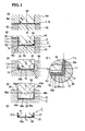
- Figure 1 is a schematic cross-sectional view for explaining the procedure of the press working in the process of producing a pressed product having a sharp corner.
- the (A) portion of Fig. 1 shows a state in which a blank plate is placed in a die.
- the (B) portion of Fig. 1 shows a state in which a pressed material is formed by the first press working.
- the (C) portion of Fig. 1 shows a state in which a punch is performing pressing in the second press working.
- the (C') portion of Fig. 1 is a partially enlarged view of the corner portion shown in the (C) portion.
- the (D) portion of Fig. 1 shows a state in which a pressed product having a sharp corner portion is formed by the second press working.
- the (E) portion of Fig. 1 shows an obtained pressed product.
- the pressed product of the present invention may be formed by using various metals having excellent press formability at a temperature range of 200°C or more and 300°C or less.
- magnesium alloys having various compositions formed by adding various elements to Mg (the remainder: Mg and impurities).
- the types of magnesium alloy include Mg-Al-based alloy, Mg-Zn-based alloy, Mg-RE (rare-earth element)-based alloy, and Y-added alloy.
- Mg-Al-based alloy which contains A1, has high corrosion resistance.
- Mg-Al-based alloy examples include, as specified in the Standards of American Society for Testing and Materials (ASTM), AZ-family alloy (Mg-Al-Zn-based alloy, Zn: 0.2 to 1.5 mass %), AM-family alloy (Mg-Al-Mn-based alloy, Mn: 0.15 to 0.5 mass %), AS-family alloy (Mg-Al-Si-based alloy, Si: 0.6 to 1.4 mass %), and Mg-Al-RE (rare-earth element)-based alloy. It is desirable that the Al content be 1.0 to at most 11 mass %.
- an Mg-Al-based alloy containing 8.3 to 9.5 mass % Al and 0.5 to 1.5 mass % Zn represented by AZ91 alloy, has excellent corrosion resistance and mechanical properties such as strength and resistance to plastic deformation in comparison with other Mg-Al-based alloys such as AZ31 alloy.
- the types of Mg-Zn-based alloy, containing Zn include, as specified in the ASTM Standards, ZK-family alloy (Mg-Zn-Zr-based alloy, Zn: 3.5 to 6.2 mass %, Zn: 0.45 mass % or more).
- the pressed product of the present invention is formed by performing press working, such as bending and deep drawing, on a metal plate.
- the peripheral surface has at least one corner portion that connects two surfaces in the peripheral surface.
- a typical shape of the pressed product has a top-plate portion (an undersurface portion) and a side-wall portion formed from the edge of the top-plate portion. More specifically, the types of the shape include a box-shaped body having a top-plate portion with the shape of a rectangular plate and only one pair of opposed side-wall portions, a box-shaped body having two pairs of opposed side-wall portions, and a lidded hollow cylindrical body having a top-plate portion with the shape of a circular plate and a hollow cylindrical side-wall portion.
- the top-plate portion and the side-wall portion each have an outside surface and an inside surface that are practically parallel to each other.
- the corner portion connecting two outside surfaces is sharp.
- top-plate portion and side-wall portion are each typically formed with a flat surface; their shape and size are not particularly limited. They may have a unitarily formed or bonded boss or the like. They may have a through hole penetrating from the outside surface to the inside surface or a groove recessed in the thickness direction. They may have a stepped shape. They may have a portion having a locally different thickness, the portion being formed by plastic working or cutting. The portion other than the corner portion has a nearly uniform thickness, except the above-described portions having a boss, a recessed portion, and a different thickness.
- the thickness "t" of the metal plate forming the pressed product is defined as the average thickness of the entire portion excluding the foregoing boss and the like and the corner portion. More specifically, five or more measuring spots are chosen from the portion other than the above-described portions such as the boss to obtain the average value.
- the foregoing thickness "t” may be the average thickness of the entire top-plate portion.
- the thickness "t” mostly depends on the thickness of the blank plate. In the case where the plate is not subjected to the press working, the thickness "t" is practically the same as that of the blank plate.
- the above-described metal plate has a thickness "t" of 0.4 mm or more and 2.0 mm or less, a pressed product having excellent strength is obtained.
- the thickness is less than 0.4 mm, because the blank plate is thin, it is easy to form a pressed product having a smaller outside corner radius R. As a result, a pressed product having very excellent appearance, such as stylishness, is obtained.
- the metal plate has a thickness "t" of 2.0 mm or less; particularly 1.5 mm or less, yet particularly 0.6 mm or less, it is expected that the pressed product of the present invention can be suitably used, for example, for the housing of a portable electronic device.
- the most noticeable feature of the pressed product of the present invention is that in the peripheral surface, at least one corner portion connecting two surfaces in the peripheral surface has an outside corner radius R that is equal to or smaller than "t.”
- the conventional pressed product made of a metal plate has had an outside corner radius larger than the thickness of the metal plate; conventionally, no pressed product has satisfied the condition that R is equal to or smaller than "t.”
- the pressed product of the present invention has at least one corner portion satisfying the condition that R is equal to or smaller than "t.”
- the corner portion when the outside corner radius R satisfies the condition that R is equal to or smaller than (2/3) x t, the corner portion can easily have a hardness higher than that of the portion other than the corner portion, such as the top-plate portion, so that the corner portion can have improved impact resistance.
- the condition that R is equal to or smaller than (1/2) ⁇ t is satisfied, the impact resistance of the corner portion and the stylishness can be further improved.
- the outside corner radius R is 0.1 mm or more, the possibility of being cut or damaged by a sharp corner portion can be reduced.
- R is 0.3 mm or less, the corner portion can have excellent impact resistance while obtaining good appearance.
- the decreasing of the outside corner radius R can be achieved, for example, by increasing the pressing pressure in the second pressing step.
- the inside corner radius "r" becomes practically 0 mm.
- the two surfaces positioned at the inside of the above-described corner portion are practically perpendicular to each other.
- Such a pressed product has an ampler internal space than the pressed product having an inside corner radius "r" that is larger than zero and therefore can be suitably used for a housing to be used to house various components.
- magnesium alloy When magnesium alloy is used to form the blank plate, it is desirable to use a rolled sheet produced by rolling a plurality of times a cast sheet produced by a continuous casting process such as the twin-roll process, particularly the casting process stated in WO/2006/003899 . Because the continuous casting process enables the rapid solidification, the creation of oxides and segregation can be decreased, so that a cast sheet having excellent rolling workability can be obtained.
- a cast sheet is subjected to heat treatment such as the solution treatment (heating temperature: 380°C to 420°C, heating time: 60 to 600 minutes) or the aging treatment, the composition can be homogenized.
- the solution treatment heating temperature: 380°C to 420°C, heating time: 60 to 600 minutes
- the aging treatment the composition can be homogenized.
- the size of the cast sheet is not particularly limited. Nevertheless, if the sheet is excessively thick, segregation tends to be created. Hence, it is desirable that the thickness be 10 mm or less, particularly 5
- the desired sheet thickness can be obtained and the average crystal grain size can be decreased.
- a magnesium alloy having a high Al content such as AZ91 alloy
- defects such as coarse impurities in crystal and coarse precipitated impurities can be eliminated, so that the press workability can be increased.
- the rolling operation may be performed by combining with a well-known condition, for example, in the case of magnesium alloy, the controlled rolling disclosed in Patent Literature 2 or the like.
- an intermediate heat treatment (heating temperature: 250°C to 350°C, heating time: 20 to 60 minutes) is conducted to remove or decrease the strain, residual stress, aggregated texture, and so on all introduced into the object to be worked through the working before the intermediate heat treatment, the subsequent rolling operation can be performed more smoothly by preventing accidental cracking, strain, and deformation.
- the obtained rolled sheet may undergo a heat treatment at 300°C or more to remove the work strain resulting from the rolling operation and to achieve complete recrystallization.
- the obtained rolled sheet may acquire strain through the use of a roller leveler or the like under a heated condition to be recrystallized during the press working.
- the press working in multiple stages be performed in a temperature range of 200°C to 300°C in every stage in order to increase the plastic workability of the object to be worked (the blank plate and pressed material).
- the use of a punch having a shoulder portion with a corner radius Rp nearly equal to zero forms a pressed material having a sharp corner portion (practically right-angled) at the inside, that is, a pressed material having an inside surface in which a corner portion is formed by two surfaces perpendicular to each other.
- the end face of the pressed material and the foregoing inside corner portion are pressed with a step-shaped punch.
- constituting materials of the blank plate are forcefully gathered at the corner portion of the die, and the forcefully gathered constituting materials are deformed in such a way that a sharp corner portion is formed at the outside of the pressed material.
- a suitable die is used, such as a movable die or a recessed die.
- heat treatment may be conducted in order to remove the strain and residual stress introduced by the press working and to improve the mechanical property.
- An example of the heat treatment condition is as follows: heating temperature: 100°C to 450°C, heating time: 5 minutes to 40 hours or so.
- a plurality of pressed products each made of magnesium alloy and having corner portions were produced to examine the outside corner radius R of the corner portions and the hardness of the pressed products.
- a plurality of cast sheets were prepared that were made of magnesium alloy having a composition equivalent to that of AZ91 alloy (Mg, 9.0 mass % Al, and 1.0 mass % Zn) and that were produced by the twin-roll continuous casting process.
- the obtained cast sheets were subjected to a plurality of rolling operations until the thickness was reduced to 0.6 mm under the following rolling conditions: roller temperature: 150°C to 250°C, sheet temperature: 200°C to 400°C, and rolling reduction per pass: 10% to 50%.
- the obtained sheet materials were subjected to blanking to prepare blank plates for the press forming.
- Figure 1 is a schematic cross-sectional view for explaining the procedure of the press working.
- Figure 1 shows the blank plate by emphasizing it.
- the first press working produces a pressed material P (a box-shaped body having outside dimensions of 45 ⁇ 95 ⁇ 6 mm) having a flat top-plate portion 10 as shown in the (B) and (C) portions of Fig. 1 and two pairs of flat side-wall portions 11 formed from the top-plate portion 10. More specifically, as shown in the (A) portion of Fig. 1 , a blank plate B having a thickness "t" of 0.6 mm is placed on a plate 51 and a die plate 52, and on the blank plate B, a punch 53 and a holding plate 54 are placed. Then, under the condition that the blank plate B is sandwiched between the plate 51 and the punch 53, the punch 53 is moved downward in Fig. 1 to form the pressed material.
- a pressed material P a box-shaped body having outside dimensions of 45 ⁇ 95 ⁇ 6 mm
- the punch 53 has a shoulder portion whose corner radius Rp is practically 0 mm, and the two surfaces forming the shoulder portion are perpendicular to each other.
- the corner portion 12 which connects the outside surface 10o of the top-plate portion 10 and the outside surface 11o of the side-wall portion 11, has an outside corner radius Ro that is larger than the thickness to of the top-plate portion 10.
- the inside surface 10i of the top-plate portion 10 and the inside surface 11i of the side-wall portion 11 are perpendicular to each other.
- the inside corner radius r 0 of the corner portion 12 is practically 0 mm.
- the plate 51, the die plate 52, the punch 53, the holding plate 54, and the below-described stepped punch 55 and die 56 all can be heated with a heating means, which is unshown.
- the heating temperature was 200°C or more.
- the second press working uses, for example, as shown in the (C) and (D) portions of Fig. 1 , a protrusion-type stepped punch 55 and a die 56 having a recessed portion to press an end face 11e of the side-wall portion 11 of the pressed material P.
- This pressing operation produces a pressed product F that has a sharp corner portion whose outside corner radius R is equal to or smaller than the thickness "t" of a metal plate 1.
- the stepped punch 55 has an end-portion-pressing face 55p and a shoulder portion 55s that, at the inside surface of the pressed material P, is brought into contact with an inside corner portion 12i, which is nearly right-angled, to press the inside corner portion 12i.
- a bottom face 56b and a side face 56s are perpendicular to each other, so that the corner portion is right-angled.
- a pressed product F in which a corner portion 22 that connects an outside surface 20o of a top-plate portion 20 and an outside surface 21o of a side-wall portion 21 has an outside corner radius R that is equal to or smaller than the thickness "t" of the top-plate portion 20.
- the thickness of the top-plate portion 20 and the side-wall portion 21 was measured using a pointed micrometer, the thickness was 0.6 mm, which is nearly equal to the thickness of the blank plate B.
- the obtained pressed product was subjected to the measurements of the outside corner radius R, the hardness of the corner portion, and the hardness of the top-plate portion. The results are shown in Table I.
- the outside corner radius R (mm) was measured by the following method. First, a pressed product was cut in a direction perpendicular to the ridge line between the outside surface of the top-plate portion and the outside surface of the side-wall portion. The cut surface was buff-polished (using diamond abrasive grain No. 200) and then observed under an optical microscope (400 power). The observed image was used to measure the radius. Similarly, the inside corner radius "r" (mm) of the corner portion was measured. The result showed that the radius was practically 0 mm and the inside surface of the top-plate portion and the inside surface of the side-wall portion were practically perpendicular to each other.
- the hardness Hv of the corner portion was measured by the following method. First, a pressed product was cut in a direction perpendicular to the ridge line between the outside surface of the top-plate portion and the outside surface of the side-wall portion. The obtained cut piece was used to produce an embedded specimen. The cut surface was mirror-polished. Three measuring spots were chosen from the center portion of the plate in the thickness direction in the cut surface of the pressed product. The hardness of the individual measuring spots was measured using a micro-Vickers hardness tester. The average value of the three measurements is shown in Table 1.
- the hardness Hv of the top-plate portion was measured by the following method. First, a part of the top-plate portion was cut from the pressed product. The obtained cut piece was used to produce an embedded specimen. The cut surface was mirror-polished. Three measuring spots were chosen from the center portion of the plate in the thickness direction in the cut surface of the top-plate portion. The hardness of the individual measuring spots was measured using a micro-Vickers hardness tester. The average value of the three measurements is shown in Table I. Alternatively, the hardness Hv may also be measured by producing an embedded specimen including both the corner portion and top-plate portion.
- the performing of the multistage hot press working described above can produce with high precision pressed products whose outside corner radius R satisfies the condition that R is equal to or smaller than the thickness "t."
- the corner portion and the top-plate portion have a comparable hardness. Consequently, because these pressed products have corner portions with high strength, it is expected that they are less likely to be deformed when they undergo an impact such as one due to the falling.
- Table I also shows that when the outside corner radius R satisfies the condition that R is equal to or smaller than (2/3) ⁇ t, the hardness of the corner portion is increased. The reason for this is attributable to the work hardening resulting from the multistage press working. Furthermore, when the outside corner radius R satisfies the condition that R is equal to or smaller than (1/2) ⁇ t, the hardness of the corner portion is significantly increased. It can be expected that these pressed products have corner portions that are excellent in impact resistance and that can accordingly maintain the sharp condition for a long time.
- test example 1 an explanation is given to the case where the corner portion connecting the top-plate portion and the side-wall portion has an outside corner radius R satisfying the condition that R is equal to or smaller than "t" in a box-type shaped body having two pairs of side-wall portions.
- a pressed product can also be produced in which a corner portion connecting the side-wall portions has an outside corner radius R satisfying the condition that R is equal to or smaller than "t.”
- a pressed product having only one pair of side-wall portions can also be produced.
- an explanation is given by referring to the unitarily formed stepped punch. Nevertheless, a stepped punch formed by combining divided pieces may also be used.
- a stepped punch may also be used that is provided with a divided piece for pressing mainly the top-plate portion and another divided piece for pressing the end face of the side-wall portion and part of the top-plate portion.
- Blank plates having various thicknesses were prepared to produce pressed products made of magnesium alloy.
- the produced pressed products were subjected to examination of strength and appearance.
- Cast sheets (thickness: 4 mm) of the same type as prepared in Test example 1 were prepared.
- the prepared cast sheets had a composition equivalent to that of AZ91 alloy and were subjected to a rolling operation by varying the number of times of rolling to produce rolled sheets having various thicknesses (thicknesses: 0.3 to 0.8 mm).
- the obtained rolled sheets were subjected to blanking to prepare blank plates.
- the individual blank plates underwent two stages of hot press working (the heating temperature at the time of pressing was selected as appropriate from the range of 200°C to 250°C).
- pressed products were produced each of which had a flat top-plate portion and two pairs of flat side-wall portions formed from the top-plate portion.
- the strength of the pressed product was measured as described below.
- the pressed product was placed such that the top-plate portion of the pressed product pointed upward on the side-wall portion used as a supporting member. Under this condition, a cemented-carbide ball having a diameter of 38 mm is pressed into the center of the top-plate portion at a load of 1 kgf (9.8 N) to deform the pressed product permanently.
- the amount of deformation (the dimensional difference between the most protruding portion and the most recessed portion in the peripheral surface of the top-plate portion) is measured with a contact profilometer. The amount of deformation is evaluated as the strength of the pressed product.
- the pressed product When the amount of deformation is 1 mm or more, the pressed product is considered to have an insufficient strength and evaluated as “poor.” When the amount of deformation is less than 1 mm, the pressed product is considered to have a sufficient strength and evaluated as “good.” When the amount of deformation is less than 0.3 mm, the pressed product is considered to have an excellent strength and evaluated as “excellent.” The results are shown in Table II.
- the appearance is evaluated through a panel test conducted by 10 panelist chosen randomly. When five or less panelists judged that the pressed product has a sharp and distinctive outside corner portion, stylishness, and excellent designability, the pressed product is evaluated as “poor.” When six to eight panelists judged as described above, the pressed product is evaluated as “good.” When nine or more panelists judged as described above, the pressed product is evaluated as “excellent.” The results are shown in Table II.
- the above-described embodiments may be changed as appropriate without deviating from the gist of the present invention and not limited to the above-described constitutions.
- the material of the metal plate may be changed from magnesium alloy to aluminum, its alloy, and other various metals.
- the pressed product of the present invention can be suitably used for various electronic devices, particularly for the housing of a portable electronic device or the like.
Landscapes
- Engineering & Computer Science (AREA)
- Mechanical Engineering (AREA)
- Shaping Metal By Deep-Drawing, Or The Like (AREA)
- Casings For Electric Apparatus (AREA)
- Forging (AREA)
Applications Claiming Priority (2)
| Application Number | Priority Date | Filing Date | Title |
|---|---|---|---|
| JP2008239712A JP2010069504A (ja) | 2008-09-18 | 2008-09-18 | プレス体 |
| PCT/JP2009/062855 WO2010032545A1 (ja) | 2008-09-18 | 2009-07-16 | プレス体 |
Publications (3)
| Publication Number | Publication Date |
|---|---|
| EP2329897A1 EP2329897A1 (en) | 2011-06-08 |
| EP2329897A4 EP2329897A4 (en) | 2012-03-07 |
| EP2329897B1 true EP2329897B1 (en) | 2013-01-09 |
Family
ID=42039387
Family Applications (1)
| Application Number | Title | Priority Date | Filing Date |
|---|---|---|---|
| EP09814390A Not-in-force EP2329897B1 (en) | 2008-09-18 | 2009-07-16 | Pressed body |
Country Status (10)
| Country | Link |
|---|---|
| US (2) | US20110165431A1 (enExample) |
| EP (1) | EP2329897B1 (enExample) |
| JP (1) | JP2010069504A (enExample) |
| KR (2) | KR20110069007A (enExample) |
| CN (2) | CN102159339A (enExample) |
| AU (1) | AU2009293983A1 (enExample) |
| BR (1) | BRPI0917892A2 (enExample) |
| RU (1) | RU2497624C2 (enExample) |
| TW (1) | TW201014661A (enExample) |
| WO (1) | WO2010032545A1 (enExample) |
Families Citing this family (18)
| Publication number | Priority date | Publication date | Assignee | Title |
|---|---|---|---|---|
| JP2010069504A (ja) * | 2008-09-18 | 2010-04-02 | Sumitomo Electric Ind Ltd | プレス体 |
| EP2735620B1 (en) * | 2011-07-21 | 2016-05-25 | Kabushiki Kaisha Kobe Seiko Sho | Method for producing hot-pressed steel member |
| WO2013094705A1 (ja) * | 2011-12-22 | 2013-06-27 | 新日鐵住金株式会社 | プレス成形品 |
| CN102553982A (zh) * | 2011-12-27 | 2012-07-11 | 苏州三维精密机械有限公司 | 小圆角高强度厚板折弯工艺 |
| US8935561B2 (en) * | 2012-02-23 | 2015-01-13 | City University Of Hong Kong | Progressive network recovery |
| JP6019960B2 (ja) * | 2012-09-07 | 2016-11-02 | 住友電気工業株式会社 | 金属成形体、および金属成形体の製造方法 |
| GB201217221D0 (en) * | 2012-09-26 | 2012-11-07 | Jaguar Cars | Panel bending method |
| JP6029085B2 (ja) * | 2012-09-26 | 2016-11-24 | 住友電気工業株式会社 | 金属成形体、及び金属成形体の製造方法 |
| JP5610104B1 (ja) * | 2012-10-23 | 2014-10-22 | 新日鐵住金株式会社 | プレス加工方法及び底付容器 |
| EP2727665B1 (de) * | 2012-10-31 | 2018-06-06 | Airbus Defence and Space GmbH | Verfahren zur Herstellung eines Formbauteils und Verwendung des Verfahrens zur Herstellung eines Formbauteils |
| KR101644765B1 (ko) * | 2013-01-09 | 2016-08-01 | 신닛테츠스미킨 카부시키카이샤 | 프레스 성형 방법 |
| DE102013103751B4 (de) | 2013-04-15 | 2025-03-27 | Thyssenkrupp Steel Europe Ag | Verfahren zur Herstellung von hochmaßhaltigen Halbschalen und Vorrichtung zur Herstellung einer Halbschale |
| DE102016118418A1 (de) * | 2016-09-29 | 2018-03-29 | Thyssenkrupp Ag | Verfahren zur Herstellung eines geformten Bauteils mit einem maßhaltigen Zargenbereich |
| KR101892469B1 (ko) * | 2016-12-05 | 2018-08-28 | 경일산업 주식회사 | 프레스를 이용한 알루미늄 케이스 성형방법 및 이에 사용되는 금형장치 |
| JP6527543B2 (ja) * | 2017-03-28 | 2019-06-05 | Jfeスチール株式会社 | プレス成形装置及びプレス成形品の製造方法 |
| JP7634184B2 (ja) * | 2020-10-22 | 2025-02-21 | パナソニックIpマネジメント株式会社 | プレス加工方法、プレス金型、およびプレス加工品 |
| GB2612022A (en) * | 2021-10-06 | 2023-04-26 | Rad Propulsion Ltd | Motor |
| CN116197308A (zh) * | 2021-11-30 | 2023-06-02 | 财团法人金属工业研究发展中心 | 壳件成形模具 |
Family Cites Families (25)
| Publication number | Priority date | Publication date | Assignee | Title |
|---|---|---|---|---|
| US4106321A (en) * | 1975-06-05 | 1978-08-15 | Mikhail Alexandrovich Platonov | Method of producing moulded parts |
| JPS53134762A (en) * | 1977-04-28 | 1978-11-24 | Sanei Kinzoku Kogyo Kk | Method and device for forming acute bend angle and drawing edge |
| JPS58135732A (ja) * | 1982-02-04 | 1983-08-12 | Shinsei Kinzoku Kogyo Kk | 端板を備えた筒体の製造方法 |
| SU1274808A1 (ru) * | 1984-11-19 | 1986-12-07 | Камское объединение по производству большегрузных автомобилей | Способ изготовлени полых изделий |
| NL8701623A (nl) * | 1987-07-10 | 1989-02-01 | Hoogovens Groep Bv | Werkwijze en inrichting voor het wandstrekken van een eendelig busvormig lichaam, alsmede aldus gevormd lichaam. |
| JPH0757385B2 (ja) * | 1989-06-13 | 1995-06-21 | 東洋製罐株式会社 | 被覆深絞り缶の製造方法 |
| CN1042098A (zh) * | 1989-11-06 | 1990-05-16 | 北票市汽车暖风机厂 | 汽车门窗框断面成型工艺 |
| RU2047412C1 (ru) * | 1992-08-14 | 1995-11-10 | Борис Ефимович Баталов | Способ изготовления изделия типа тонкостенного сосуда и заготовка для комбинированной вытяжки стакана |
| JPH06210389A (ja) * | 1993-01-16 | 1994-08-02 | Toyota Tekko Kk | 有底筒状部品の製造方法 |
| JPH091253A (ja) * | 1995-06-20 | 1997-01-07 | Komaki Press Kogyo Kk | 板金プレス加工方法 |
| US20020005408A1 (en) * | 1997-08-12 | 2002-01-17 | Yuji Yamasaki | Easy-opening can end |
| US6205831B1 (en) * | 1998-10-08 | 2001-03-27 | Rayovac Corporation | Method for making a cathode can from metal strip |
| JP2001225113A (ja) * | 2000-02-14 | 2001-08-21 | Sasayama:Kk | 板金プレス加工方法 |
| CN1163321C (zh) * | 2000-09-25 | 2004-08-25 | 富金精密工业(深圳)有限公司 | 金属板材卷圆压平成形方法 |
| JP2002239644A (ja) | 2001-02-20 | 2002-08-27 | Matsushita Electric Ind Co Ltd | 角絞り加工法とその金型 |
| JP3771203B2 (ja) * | 2002-07-30 | 2006-04-26 | 独立行政法人産業技術総合研究所 | マグネシウム合金製板材の深絞り成形方法およびその成形体 |
| US20080229802A1 (en) * | 2004-01-28 | 2008-09-25 | Glud & Marstrand A/S | Method of Forming a Metal Sheet Blank |
| US7841380B2 (en) * | 2004-06-30 | 2010-11-30 | Sumitomo Electric Industries, Ltd. | Producing method for magnesium alloy material |
| JP4963527B2 (ja) * | 2004-07-15 | 2012-06-27 | 東洋鋼鈑株式会社 | 成形加工用マグネシウム合金板、マグネシウム合金容器およびマグネシウム合金容器の製造方法 |
| JP2006159232A (ja) * | 2004-12-06 | 2006-06-22 | Tsutsumi Industries Inc | プレス加工方法における薄板断面成型法 |
| JP4730601B2 (ja) * | 2005-03-28 | 2011-07-20 | 住友電気工業株式会社 | マグネシウム合金板の製造方法 |
| US7761971B2 (en) * | 2005-08-24 | 2010-07-27 | Meyer Intellectual Properties Limited | Cookware with flat interior surface |
| US7980158B1 (en) * | 2007-04-19 | 2011-07-19 | The United States Of America As Represented By The Secretary Of The Army | Polyurethane press tooling components |
| CN201098710Y (zh) * | 2007-08-28 | 2008-08-13 | 汉达精密电子(昆山)有限公司 | 金属板材冲压装置 |
| JP2010069504A (ja) * | 2008-09-18 | 2010-04-02 | Sumitomo Electric Ind Ltd | プレス体 |
-
2008
- 2008-09-18 JP JP2008239712A patent/JP2010069504A/ja active Pending
-
2009
- 2009-07-16 AU AU2009293983A patent/AU2009293983A1/en not_active Abandoned
- 2009-07-16 BR BRPI0917892A patent/BRPI0917892A2/pt not_active IP Right Cessation
- 2009-07-16 RU RU2011114987/02A patent/RU2497624C2/ru not_active IP Right Cessation
- 2009-07-16 EP EP09814390A patent/EP2329897B1/en not_active Not-in-force
- 2009-07-16 WO PCT/JP2009/062855 patent/WO2010032545A1/ja not_active Ceased
- 2009-07-16 KR KR1020117005946A patent/KR20110069007A/ko not_active Ceased
- 2009-07-16 CN CN2009801368145A patent/CN102159339A/zh active Pending
- 2009-07-16 CN CN201510941099.XA patent/CN105537350A/zh active Pending
- 2009-07-16 US US13/063,657 patent/US20110165431A1/en not_active Abandoned
- 2009-07-16 KR KR1020167002938A patent/KR20160020585A/ko not_active Ceased
- 2009-09-11 TW TW098130639A patent/TW201014661A/zh unknown
-
2012
- 2012-12-14 US US13/716,039 patent/US20130104619A1/en not_active Abandoned
Also Published As
| Publication number | Publication date |
|---|---|
| RU2011114987A (ru) | 2012-10-27 |
| RU2497624C2 (ru) | 2013-11-10 |
| US20130104619A1 (en) | 2013-05-02 |
| BRPI0917892A2 (pt) | 2015-12-01 |
| CN105537350A (zh) | 2016-05-04 |
| CN102159339A (zh) | 2011-08-17 |
| KR20110069007A (ko) | 2011-06-22 |
| JP2010069504A (ja) | 2010-04-02 |
| WO2010032545A1 (ja) | 2010-03-25 |
| EP2329897A1 (en) | 2011-06-08 |
| AU2009293983A1 (en) | 2010-03-25 |
| EP2329897A4 (en) | 2012-03-07 |
| KR20160020585A (ko) | 2016-02-23 |
| TW201014661A (en) | 2010-04-16 |
| US20110165431A1 (en) | 2011-07-07 |
Similar Documents
| Publication | Publication Date | Title |
|---|---|---|
| EP2329897B1 (en) | Pressed body | |
| KR101051194B1 (ko) | 마그네슘 합금판 및 그 제조방법 | |
| CN101885251A (zh) | 用于车辆板件的多合金复合薄板 | |
| JP6029085B2 (ja) | 金属成形体、及び金属成形体の製造方法 | |
| CN102470407A (zh) | 钛板及钛板的制造方法 | |
| EP2447381A1 (en) | Magnesium alloy plate | |
| US20120107171A1 (en) | Magnesium alloy sheet | |
| CN109097640B (zh) | 一种用于手机中板可蚀刻高强度铝的制造方法 | |
| EP2958748B1 (en) | Clad automotive body panel with sharp character lines | |
| JP5374993B2 (ja) | マグネシウム合金成形体、及びマグネシウム合金成形体の製造方法 | |
| AU2015315865A1 (en) | Aluminum alloy sheet for can body | |
| JP5376507B2 (ja) | 優れた冷間成形性を有するマグネシウム合金板材及びその製造方法 | |
| KR101885397B1 (ko) | 마그네슘 합금재 및 그의 제조 방법 | |
| JP5937865B2 (ja) | プレス成形性と強度のバランス、及び耐食性に優れた純チタン板の製造方法 | |
| CA2887468C (en) | Aluminum alloy sheet for blow molding and production method therefor | |
| CN108501471A (zh) | 电子设备用轧制接合体及电子设备用壳体 | |
| JP2014221493A (ja) | プレス体 | |
| US20220184923A1 (en) | Roll-bonded laminate and method for producing the same | |
| JP2002003968A (ja) | 成形性に優れたチタン板とその製造方法 | |
| US11840045B2 (en) | Roll-bonded laminate | |
| Oluwole et al. | Effect of draw ratio and sheet thickness on earing and drawability of Al 1200 cups | |
| CN114480928A (zh) | 一种电子产品用高强铝板及其制造方法 | |
| CN112458345B (zh) | 一种笔电平板高强度氧化铝6s50的制造方法 | |
| EP3741880A1 (en) | Sheet metal product with high bendability and manufacturing thereof | |
| WO2007111002A1 (ja) | 高成形性アルミニウム材料 |
Legal Events
| Date | Code | Title | Description |
|---|---|---|---|
| PUAI | Public reference made under article 153(3) epc to a published international application that has entered the european phase |
Free format text: ORIGINAL CODE: 0009012 |
|
| 17P | Request for examination filed |
Effective date: 20110309 |
|
| AK | Designated contracting states |
Kind code of ref document: A1 Designated state(s): AT BE BG CH CY CZ DE DK EE ES FI FR GB GR HR HU IE IS IT LI LT LU LV MC MK MT NL NO PL PT RO SE SI SK SM TR |
|
| AX | Request for extension of the european patent |
Extension state: AL BA RS |
|
| DAX | Request for extension of the european patent (deleted) | ||
| A4 | Supplementary search report drawn up and despatched |
Effective date: 20120203 |
|
| RIC1 | Information provided on ipc code assigned before grant |
Ipc: B21D 22/20 20060101ALI20120130BHEP Ipc: B21D 22/02 20060101ALI20120130BHEP Ipc: B21D 51/52 20060101ALI20120130BHEP Ipc: B21D 51/18 20060101AFI20120130BHEP |
|
| GRAP | Despatch of communication of intention to grant a patent |
Free format text: ORIGINAL CODE: EPIDOSNIGR1 |
|
| GRAS | Grant fee paid |
Free format text: ORIGINAL CODE: EPIDOSNIGR3 |
|
| GRAA | (expected) grant |
Free format text: ORIGINAL CODE: 0009210 |
|
| AK | Designated contracting states |
Kind code of ref document: B1 Designated state(s): AT BE BG CH CY CZ DE DK EE ES FI FR GB GR HR HU IE IS IT LI LT LU LV MC MK MT NL NO PL PT RO SE SI SK SM TR |
|
| REG | Reference to a national code |
Ref country code: GB Ref legal event code: FG4D |
|
| REG | Reference to a national code |
Ref country code: AT Ref legal event code: REF Ref document number: 592432 Country of ref document: AT Kind code of ref document: T Effective date: 20130115 Ref country code: CH Ref legal event code: EP |
|
| REG | Reference to a national code |
Ref country code: IE Ref legal event code: FG4D |
|
| REG | Reference to a national code |
Ref country code: DE Ref legal event code: R096 Ref document number: 602009012737 Country of ref document: DE Effective date: 20130314 |
|
| PG25 | Lapsed in a contracting state [announced via postgrant information from national office to epo] |
Ref country code: SI Free format text: LAPSE BECAUSE OF FAILURE TO SUBMIT A TRANSLATION OF THE DESCRIPTION OR TO PAY THE FEE WITHIN THE PRESCRIBED TIME-LIMIT Effective date: 20130109 |
|
| REG | Reference to a national code |
Ref country code: NL Ref legal event code: VDEP Effective date: 20130109 |
|
| REG | Reference to a national code |
Ref country code: AT Ref legal event code: MK05 Ref document number: 592432 Country of ref document: AT Kind code of ref document: T Effective date: 20130109 |
|
| REG | Reference to a national code |
Ref country code: LT Ref legal event code: MG4D |
|
| PG25 | Lapsed in a contracting state [announced via postgrant information from national office to epo] |
Ref country code: IS Free format text: LAPSE BECAUSE OF FAILURE TO SUBMIT A TRANSLATION OF THE DESCRIPTION OR TO PAY THE FEE WITHIN THE PRESCRIBED TIME-LIMIT Effective date: 20130509 Ref country code: NO Free format text: LAPSE BECAUSE OF FAILURE TO SUBMIT A TRANSLATION OF THE DESCRIPTION OR TO PAY THE FEE WITHIN THE PRESCRIBED TIME-LIMIT Effective date: 20130409 Ref country code: LT Free format text: LAPSE BECAUSE OF FAILURE TO SUBMIT A TRANSLATION OF THE DESCRIPTION OR TO PAY THE FEE WITHIN THE PRESCRIBED TIME-LIMIT Effective date: 20130109 Ref country code: SE Free format text: LAPSE BECAUSE OF FAILURE TO SUBMIT A TRANSLATION OF THE DESCRIPTION OR TO PAY THE FEE WITHIN THE PRESCRIBED TIME-LIMIT Effective date: 20130109 Ref country code: ES Free format text: LAPSE BECAUSE OF FAILURE TO SUBMIT A TRANSLATION OF THE DESCRIPTION OR TO PAY THE FEE WITHIN THE PRESCRIBED TIME-LIMIT Effective date: 20130420 Ref country code: AT Free format text: LAPSE BECAUSE OF FAILURE TO SUBMIT A TRANSLATION OF THE DESCRIPTION OR TO PAY THE FEE WITHIN THE PRESCRIBED TIME-LIMIT Effective date: 20130109 Ref country code: BE Free format text: LAPSE BECAUSE OF FAILURE TO SUBMIT A TRANSLATION OF THE DESCRIPTION OR TO PAY THE FEE WITHIN THE PRESCRIBED TIME-LIMIT Effective date: 20130109 Ref country code: BG Free format text: LAPSE BECAUSE OF FAILURE TO SUBMIT A TRANSLATION OF THE DESCRIPTION OR TO PAY THE FEE WITHIN THE PRESCRIBED TIME-LIMIT Effective date: 20130409 |
|
| PG25 | Lapsed in a contracting state [announced via postgrant information from national office to epo] |
Ref country code: FI Free format text: LAPSE BECAUSE OF FAILURE TO SUBMIT A TRANSLATION OF THE DESCRIPTION OR TO PAY THE FEE WITHIN THE PRESCRIBED TIME-LIMIT Effective date: 20130109 Ref country code: GR Free format text: LAPSE BECAUSE OF FAILURE TO SUBMIT A TRANSLATION OF THE DESCRIPTION OR TO PAY THE FEE WITHIN THE PRESCRIBED TIME-LIMIT Effective date: 20130410 Ref country code: PT Free format text: LAPSE BECAUSE OF FAILURE TO SUBMIT A TRANSLATION OF THE DESCRIPTION OR TO PAY THE FEE WITHIN THE PRESCRIBED TIME-LIMIT Effective date: 20130509 Ref country code: PL Free format text: LAPSE BECAUSE OF FAILURE TO SUBMIT A TRANSLATION OF THE DESCRIPTION OR TO PAY THE FEE WITHIN THE PRESCRIBED TIME-LIMIT Effective date: 20130109 Ref country code: LV Free format text: LAPSE BECAUSE OF FAILURE TO SUBMIT A TRANSLATION OF THE DESCRIPTION OR TO PAY THE FEE WITHIN THE PRESCRIBED TIME-LIMIT Effective date: 20130109 Ref country code: NL Free format text: LAPSE BECAUSE OF FAILURE TO SUBMIT A TRANSLATION OF THE DESCRIPTION OR TO PAY THE FEE WITHIN THE PRESCRIBED TIME-LIMIT Effective date: 20130109 |
|
| PG25 | Lapsed in a contracting state [announced via postgrant information from national office to epo] |
Ref country code: HR Free format text: LAPSE BECAUSE OF FAILURE TO SUBMIT A TRANSLATION OF THE DESCRIPTION OR TO PAY THE FEE WITHIN THE PRESCRIBED TIME-LIMIT Effective date: 20130109 |
|
| PG25 | Lapsed in a contracting state [announced via postgrant information from national office to epo] |
Ref country code: RO Free format text: LAPSE BECAUSE OF FAILURE TO SUBMIT A TRANSLATION OF THE DESCRIPTION OR TO PAY THE FEE WITHIN THE PRESCRIBED TIME-LIMIT Effective date: 20130109 Ref country code: CZ Free format text: LAPSE BECAUSE OF FAILURE TO SUBMIT A TRANSLATION OF THE DESCRIPTION OR TO PAY THE FEE WITHIN THE PRESCRIBED TIME-LIMIT Effective date: 20130109 Ref country code: DK Free format text: LAPSE BECAUSE OF FAILURE TO SUBMIT A TRANSLATION OF THE DESCRIPTION OR TO PAY THE FEE WITHIN THE PRESCRIBED TIME-LIMIT Effective date: 20130109 Ref country code: SK Free format text: LAPSE BECAUSE OF FAILURE TO SUBMIT A TRANSLATION OF THE DESCRIPTION OR TO PAY THE FEE WITHIN THE PRESCRIBED TIME-LIMIT Effective date: 20130109 Ref country code: EE Free format text: LAPSE BECAUSE OF FAILURE TO SUBMIT A TRANSLATION OF THE DESCRIPTION OR TO PAY THE FEE WITHIN THE PRESCRIBED TIME-LIMIT Effective date: 20130109 |
|
| PLBE | No opposition filed within time limit |
Free format text: ORIGINAL CODE: 0009261 |
|
| STAA | Information on the status of an ep patent application or granted ep patent |
Free format text: STATUS: NO OPPOSITION FILED WITHIN TIME LIMIT |
|
| PG25 | Lapsed in a contracting state [announced via postgrant information from national office to epo] |
Ref country code: CY Free format text: LAPSE BECAUSE OF FAILURE TO SUBMIT A TRANSLATION OF THE DESCRIPTION OR TO PAY THE FEE WITHIN THE PRESCRIBED TIME-LIMIT Effective date: 20130109 |
|
| 26N | No opposition filed |
Effective date: 20131010 |
|
| PG25 | Lapsed in a contracting state [announced via postgrant information from national office to epo] |
Ref country code: IT Free format text: LAPSE BECAUSE OF FAILURE TO SUBMIT A TRANSLATION OF THE DESCRIPTION OR TO PAY THE FEE WITHIN THE PRESCRIBED TIME-LIMIT Effective date: 20130109 |
|
| REG | Reference to a national code |
Ref country code: DE Ref legal event code: R097 Ref document number: 602009012737 Country of ref document: DE Effective date: 20131010 |
|
| PG25 | Lapsed in a contracting state [announced via postgrant information from national office to epo] |
Ref country code: MC Free format text: LAPSE BECAUSE OF FAILURE TO SUBMIT A TRANSLATION OF THE DESCRIPTION OR TO PAY THE FEE WITHIN THE PRESCRIBED TIME-LIMIT Effective date: 20130109 |
|
| REG | Reference to a national code |
Ref country code: CH Ref legal event code: PL |
|
| REG | Reference to a national code |
Ref country code: IE Ref legal event code: MM4A |
|
| PG25 | Lapsed in a contracting state [announced via postgrant information from national office to epo] |
Ref country code: LI Free format text: LAPSE BECAUSE OF NON-PAYMENT OF DUE FEES Effective date: 20130731 Ref country code: CH Free format text: LAPSE BECAUSE OF NON-PAYMENT OF DUE FEES Effective date: 20130731 |
|
| PG25 | Lapsed in a contracting state [announced via postgrant information from national office to epo] |
Ref country code: IE Free format text: LAPSE BECAUSE OF NON-PAYMENT OF DUE FEES Effective date: 20130716 |
|
| PG25 | Lapsed in a contracting state [announced via postgrant information from national office to epo] |
Ref country code: SM Free format text: LAPSE BECAUSE OF FAILURE TO SUBMIT A TRANSLATION OF THE DESCRIPTION OR TO PAY THE FEE WITHIN THE PRESCRIBED TIME-LIMIT Effective date: 20130109 |
|
| PG25 | Lapsed in a contracting state [announced via postgrant information from national office to epo] |
Ref country code: TR Free format text: LAPSE BECAUSE OF FAILURE TO SUBMIT A TRANSLATION OF THE DESCRIPTION OR TO PAY THE FEE WITHIN THE PRESCRIBED TIME-LIMIT Effective date: 20130109 Ref country code: MT Free format text: LAPSE BECAUSE OF FAILURE TO SUBMIT A TRANSLATION OF THE DESCRIPTION OR TO PAY THE FEE WITHIN THE PRESCRIBED TIME-LIMIT Effective date: 20130109 |
|
| PG25 | Lapsed in a contracting state [announced via postgrant information from national office to epo] |
Ref country code: LU Free format text: LAPSE BECAUSE OF NON-PAYMENT OF DUE FEES Effective date: 20130716 Ref country code: HU Free format text: LAPSE BECAUSE OF FAILURE TO SUBMIT A TRANSLATION OF THE DESCRIPTION OR TO PAY THE FEE WITHIN THE PRESCRIBED TIME-LIMIT; INVALID AB INITIO Effective date: 20090716 Ref country code: MK Free format text: LAPSE BECAUSE OF FAILURE TO SUBMIT A TRANSLATION OF THE DESCRIPTION OR TO PAY THE FEE WITHIN THE PRESCRIBED TIME-LIMIT Effective date: 20130109 |
|
| REG | Reference to a national code |
Ref country code: FR Ref legal event code: PLFP Year of fee payment: 8 |
|
| REG | Reference to a national code |
Ref country code: FR Ref legal event code: PLFP Year of fee payment: 9 |
|
| PGFP | Annual fee paid to national office [announced via postgrant information from national office to epo] |
Ref country code: FR Payment date: 20170613 Year of fee payment: 9 |
|
| REG | Reference to a national code |
Ref country code: DE Ref legal event code: R084 Ref document number: 602009012737 Country of ref document: DE |
|
| REG | Reference to a national code |
Ref country code: GB Ref legal event code: 746 Effective date: 20180220 |
|
| PG25 | Lapsed in a contracting state [announced via postgrant information from national office to epo] |
Ref country code: FR Free format text: LAPSE BECAUSE OF NON-PAYMENT OF DUE FEES Effective date: 20180731 |
|
| PGFP | Annual fee paid to national office [announced via postgrant information from national office to epo] |
Ref country code: GB Payment date: 20210623 Year of fee payment: 13 |
|
| PGFP | Annual fee paid to national office [announced via postgrant information from national office to epo] |
Ref country code: DE Payment date: 20210622 Year of fee payment: 13 |
|
| REG | Reference to a national code |
Ref country code: DE Ref legal event code: R119 Ref document number: 602009012737 Country of ref document: DE |
|
| GBPC | Gb: european patent ceased through non-payment of renewal fee |
Effective date: 20220716 |
|
| PG25 | Lapsed in a contracting state [announced via postgrant information from national office to epo] |
Ref country code: GB Free format text: LAPSE BECAUSE OF NON-PAYMENT OF DUE FEES Effective date: 20220716 Ref country code: DE Free format text: LAPSE BECAUSE OF NON-PAYMENT OF DUE FEES Effective date: 20230201 |