EP2325040A1 - Coque de confort contrôlable pour siège de véhicule - Google Patents
Coque de confort contrôlable pour siège de véhicule Download PDFInfo
- Publication number
- EP2325040A1 EP2325040A1 EP10014831A EP10014831A EP2325040A1 EP 2325040 A1 EP2325040 A1 EP 2325040A1 EP 10014831 A EP10014831 A EP 10014831A EP 10014831 A EP10014831 A EP 10014831A EP 2325040 A1 EP2325040 A1 EP 2325040A1
- Authority
- EP
- European Patent Office
- Prior art keywords
- support panel
- support
- panel
- deformable
- shape
- Prior art date
- Legal status (The legal status is an assumption and is not a legal conclusion. Google has not performed a legal analysis and makes no representation as to the accuracy of the status listed.)
- Granted
Links
- 241001274197 Scatophagus argus Species 0.000 claims abstract description 20
- 239000013013 elastic material Substances 0.000 claims description 10
- 210000004705 lumbosacral region Anatomy 0.000 claims description 10
- 230000001939 inductive effect Effects 0.000 claims description 6
- 239000000463 material Substances 0.000 claims description 4
- 230000003213 activating effect Effects 0.000 claims description 3
- 230000004913 activation Effects 0.000 claims description 3
- 230000013011 mating Effects 0.000 claims description 2
- 230000036544 posture Effects 0.000 description 17
- 238000010276 construction Methods 0.000 description 3
- 230000001276 controlling effect Effects 0.000 description 3
- 239000006260 foam Substances 0.000 description 2
- 239000004033 plastic Substances 0.000 description 2
- 229920003023 plastic Polymers 0.000 description 2
- 230000002889 sympathetic effect Effects 0.000 description 2
- 206010012374 Depressed mood Diseases 0.000 description 1
- 206010023509 Kyphosis Diseases 0.000 description 1
- 208000007623 Lordosis Diseases 0.000 description 1
- 239000000654 additive Substances 0.000 description 1
- 230000000996 additive effect Effects 0.000 description 1
- 230000008878 coupling Effects 0.000 description 1
- 238000010168 coupling process Methods 0.000 description 1
- 238000005859 coupling reaction Methods 0.000 description 1
- 239000004744 fabric Substances 0.000 description 1
- 235000013312 flour Nutrition 0.000 description 1
- 238000002955 isolation Methods 0.000 description 1
- 230000001045 lordotic effect Effects 0.000 description 1
- 239000002991 molded plastic Substances 0.000 description 1
- 230000001105 regulatory effect Effects 0.000 description 1
- 210000000115 thoracic cavity Anatomy 0.000 description 1
Images


Classifications
-
- B—PERFORMING OPERATIONS; TRANSPORTING
- B60—VEHICLES IN GENERAL
- B60N—SEATS SPECIALLY ADAPTED FOR VEHICLES; VEHICLE PASSENGER ACCOMMODATION NOT OTHERWISE PROVIDED FOR
- B60N2/00—Seats specially adapted for vehicles; Arrangement or mounting of seats in vehicles
- B60N2/64—Back-rests or cushions
- B60N2/66—Lumbar supports
- B60N2/667—Lumbar supports having flexible support member bowed by applied forces
- B60N2/6673—Lumbar supports having flexible support member bowed by applied forces with motor driven adjustments
-
- B—PERFORMING OPERATIONS; TRANSPORTING
- B60—VEHICLES IN GENERAL
- B60N—SEATS SPECIALLY ADAPTED FOR VEHICLES; VEHICLE PASSENGER ACCOMMODATION NOT OTHERWISE PROVIDED FOR
- B60N2/00—Seats specially adapted for vehicles; Arrangement or mounting of seats in vehicles
- B60N2/02—Seats specially adapted for vehicles; Arrangement or mounting of seats in vehicles the seat or part thereof being movable, e.g. adjustable
- B60N2/0224—Non-manual adjustments, e.g. with electrical operation
- B60N2/02246—Electric motors therefor
-
- B—PERFORMING OPERATIONS; TRANSPORTING
- B60—VEHICLES IN GENERAL
- B60N—SEATS SPECIALLY ADAPTED FOR VEHICLES; VEHICLE PASSENGER ACCOMMODATION NOT OTHERWISE PROVIDED FOR
- B60N2/00—Seats specially adapted for vehicles; Arrangement or mounting of seats in vehicles
- B60N2/02—Seats specially adapted for vehicles; Arrangement or mounting of seats in vehicles the seat or part thereof being movable, e.g. adjustable
- B60N2/22—Seats specially adapted for vehicles; Arrangement or mounting of seats in vehicles the seat or part thereof being movable, e.g. adjustable the back-rest being adjustable
- B60N2/2231—Worm and worm gear articulations
-
- B—PERFORMING OPERATIONS; TRANSPORTING
- B60—VEHICLES IN GENERAL
- B60N—SEATS SPECIALLY ADAPTED FOR VEHICLES; VEHICLE PASSENGER ACCOMMODATION NOT OTHERWISE PROVIDED FOR
- B60N2/00—Seats specially adapted for vehicles; Arrangement or mounting of seats in vehicles
- B60N2/64—Back-rests or cushions
- B60N2/643—Back-rests or cushions shape of the back-rests
-
- B—PERFORMING OPERATIONS; TRANSPORTING
- B60—VEHICLES IN GENERAL
- B60N—SEATS SPECIALLY ADAPTED FOR VEHICLES; VEHICLE PASSENGER ACCOMMODATION NOT OTHERWISE PROVIDED FOR
- B60N2/00—Seats specially adapted for vehicles; Arrangement or mounting of seats in vehicles
- B60N2/64—Back-rests or cushions
- B60N2/66—Lumbar supports
- B60N2/667—Lumbar supports having flexible support member bowed by applied forces
-
- B—PERFORMING OPERATIONS; TRANSPORTING
- B60—VEHICLES IN GENERAL
- B60N—SEATS SPECIALLY ADAPTED FOR VEHICLES; VEHICLE PASSENGER ACCOMMODATION NOT OTHERWISE PROVIDED FOR
- B60N2/00—Seats specially adapted for vehicles; Arrangement or mounting of seats in vehicles
- B60N2/68—Seat frames
Definitions
- the present disclosure relates to a vehicle seat, and particularly to a seat including an expandable and contractable portion. More particularly, the present disclosure relates to a vehicle seat including a seat back having a variable shape.
- a vehicle scat includes a seat back.
- the vehicle seat also includes a seat bottom and the seat back extends upwardly from the seat bottom.
- the seat back includes a backrest support frame adapted to be coupled to a foundation mounted on a floor of a vehicle and a backrest in front of the backrest support frame.
- the backrest includes a deformable back-support panel defined, for example, by a thin pliable contoured shell made of a pliable plastics material. Owing to its pliability, the deformable back-support panel is configured to deform and change shape in use to suit the size, shape, and spinal orientation of a passenger seated in the vehicle seat.
- a panel-motion controller is configured to change the shape of the back-support panel under the command and control of a passenger seated in the seat.
- the panel-motion controller is located behind the deformable back-support panel.
- the panel-motion controller includes a lower control unit including motor-driven means for changing the shape of the back-support panel to adjust the posture of the seated passenger.
- the lower control unit is responsive to commands of the scat passenger to operate a motor to move a shape-control link coupled to the back-support panel to cause the shape of the back-support panel to change to assume a selected shape.
- the panel-motion controller includes lower and upper control units and each control unit includes a yieldable spring.
- Each of these units is configured to use those yieldable springs to provide passenger motion-driven means for passively changing the shape of the back-support panel in response to rearward movement of the seated passenger against the seat back.
- the springs in the lower and upper control units operate independently and in combination to change the shape of the deformable back-support panel (from the selected shape) temporarily to enhance posture support provided to the passenger in response to slouching, sinking, or other posture-changing movement of the seated passenger in the vehicle seat after the lower control unit has been used to establish a selected shape of the deformable back-support panel.
- a vehicle seat includes a seat back and a back-support panel-motion controller.
- the seat back includes a backrest support and a backrest.
- the backrest includes a deformable back-support panel configured to bend and flex to move relative to the backrest support to assume many different shapes to provide custom spinal column support to a passenger seated in the vehicle seat adjacent to the deformable back-support panel.
- the back-support panel-motion controller is coupled to the deformable back-support panel.
- the back-support panel-motion controller is configured to provide means operable by a passenger seated in the vehicle seat for moving the deformable back-support panel relative to the backrest support in an initial stage of active operation to assume a selected shape in response to activation of an actuator included in the back-support panel-motion controller.
- the back-support panel-motion controller is also configured to provide means for independently allowing the selected shape of the deformable back-support panel to vary passively after assumption of the selected shape in a subsequent stage of passive operation without activating the actuator in response to forces applied by a torso of a seated passenger leaning against the deformable back-support panel as the seated passenger shifts position relative to the seat back to assume a new posture in the vehicle seat.
- the vehicle seat further includes a scat bottom that is adapted to lie under and support the seated passenger.
- the seat back is arranged to extend upwardly from the seat bottom.
- the deformable back-support panel includes an upper portion and a lower portion.
- the upper portion is arranged to lie in spaced-apart relation to the seat bottom.
- the lower portion is arranged to lic between the seat bottom and the upper portion.
- the back-support panel-motion controller includes a lower control unit coupled to the lower portion of the deformable back-support panel and is configured to provide active-motion means for actively moving the deformable back-support panel relative to the backrest support to cause the shape of the deformable back-support panel to change to assume the selected shape so that lumbar support for a seated passenger leaning against the seat back is varied to suit the passenger.
- the lower control unit is configured to provide lower passive-motion means for passively allowing shape-changing movement of the deformable back-support panel temporarily away from the selected shape and relative to the backrest support in response to rearwardly directed forces applied by a seated passenger during a shift in position of the seated passenger on the seat bottom and relative to the seat back to assume a new posture in the vehicle scat.
- the lower control unit includes a lower panel mount, a link mover, and a shape-control link.
- the lower control unit in particular is coupled to the lower portion of the deformable back-support panel.
- the link mover in particular is separated from the deformable back-support panel.
- the shape-control link in particular is arranged to interconnect the lower panel mount and the link mover.
- the link mover is configured to provide means for actively moving the shape-control link relative to the backrest support to cause movement of the lower portion of the deformable back-support panel relative to the backrest support so that the shape of the deformable back-support panel is varied to assume the selected shape to suit the seated passenger.
- the shape-control link includes a yieldable spring made of an clastic material.
- the yieldable spring is configured to yield elastically when the deformable back-support panel has assumed the selected shape during exposure of the deformable back-support panel to rearwardly directed forces applied by the seated passenger during a change in posture of the seated passenger to allow the deformable back-support panel to assume temporarily a changed shape only as long as the rearwardly directed forces are applied to the deformable back-support panel by the seated passenger.
- the shape-control link comprises an input block, an output block, and a yieldable spring.
- the input block in particular is coupled to the link mover.
- the output block in particular is coupled to the lower panel mount using an axle rod.
- the yieldable spring in particular is made of an elastic material and is arranged to interconnect the input and output blocks.
- the input block comprises a driven gear and a pivot rod coupled to the driven gear to support the driven gear for rotation about a pivot axis.
- the output block is coupled to another end of the yieldable spring and the link mover is arranged to engage the driven gear and rotate about an axis to rotate the driven gear about a pivot axis to cause the shape-control link to move relative to the backrest support.
- the input block further comprises a clamp coupled to one end of the yieldable spring.
- the pivot rod in particular is also coupled to the clamp.
- the yieldable spring in particular is a leaf spring.
- the yieldable spring is a spiral clock spring.
- an inner end of the spiral clock spring is coupled to the output block.
- an outer end of the spiral clock spring is coupled to the input block.
- the spiral clock spring in particular is arranged to spiral around a central axis established by the pivot rod.
- the output block is a bar that includes a first member and a second member.
- the first member in particular is coupled to the pivot rod and the second member in particular is coupled to the axle rod and is arranged to define an obtuse included angle therebetween.
- the link mover includes a worm, a motor, and a motor actuator.
- the worm is configured to mate with the driven gear to establish a worm drive and to rotate the driven gear about the pivot axis to load or unload the yieldable spring to cause the deformable back-support panel to change shape.
- the motor is configured to provide means for rotating the worm about an axis of rotation.
- the motor actuator is coupled to the motor and is configured to actuate the motor at the command of a seated passenger.
- the link mover includes a ratchet mounted for rotation about an axis of rotation.
- the ratchet includes teeth mating with the driven gear and a handle configured to provide means for moving the teeth about the pivot axis to turn the driven gear about the pivot axis to load or unload the yieldable spring to cause the deformable back-support panel to change shape.
- the back-support panel-motion controller further includes an upper control unit coupled to the upper portion of the deformable block-support portion.
- the back-support panel-motion controller is configured to provide passive-motion means for passively allowing shape-changing movement of the deformable back-support panel relative to the backrest support temporarily in response to rearwardly directed forces applied by a lumbar region of a back of a seated passenger when the seated passenger slouches to move in a rearward direction toward the deformable back-support panel.
- the upper control unit includes an upper panel mount and a shape-control link.
- the upper panel mount in particular is coupled to the upper portion of the deformable back-support panel.
- the shape-control link in particular is coupled to the upper panel mount and is configured to include a yieldable spring made of an elastic material and is configured to yield elastically in response to application of movement-inducing forces applied to the deformable back-support panel by a seated passenger during a change in posture of the seated passenger.
- the seat back further includes a panel carrier interposed between the deformable back-support panel and the backrest support.
- the panel carrier in particular is formed to include an opening.
- a lower portion of the back-support panel-motion controller in particular is arranged to interconnect the backrest support and the deformable back-support panel and extend through the opening formed in the panel carrier.
- An upper portion of the back-support panel-motion controller in particular is arranged to interconnect the deformable back-support panel and the panel carrier.
- the vehicle seat further includes a seat bottom adapted to lie under and support the seated passenger.
- the seat is arranged to extend upwardly from the seat bottom.
- the deformable back-support panel includes an upper portion and a lower portion.
- the upper portion is arranged to lie in spaced-apart relation to the seat bottom.
- the lower portion is arranged to lie between the seat bottom and the upper portion.
- the upper portion of the back-support panel-motion controller is coupled to the upper portion of the deformable back-support panel and the lower portion of the back-support panel-motion controller is coupled to the lower portion of the deformable back-support panel.
- a vehicle seat includes a seat bottom, a seat back, and a back-support panel-motion controller.
- the seat back extends upwardly from the seat bottom and includes a deformable back-support panel having an initial shape and including an upper portion arranged to lie in spaced-apart relation to the seat bottom and a lower portion arranged to lie between the seat bottom and the upper portion.
- the back-support panel-motion controller is configured to change the shape of the deformable back-support panel under the command and control of a seated passenger seated on the seat bottom.
- the back-support panel-motion controller includes a lower control unit including active-motion means coupled to the lower portion of the deformable back-support panel for actively changing the shape of the deformable back-support panel to assume a selected shape different from the initial shape to adjust the posture of the seated passenger.
- the active-motion means includes a yieldable spring made of an elastic material and is configured to yield elastically when the deformable back-support panel has assumed the selected shape during exposure of the deformable back-support panel to rearwardly directed forces applied by the seated passenger during a change in posture of the seated passenger to allow the deformable back-support panel to assume temporarily a changed shape only as long as the rearwardly directed forces are applied to the deformable back-support panel by the seated passenger.
- the back-support panel-motion controller further includes an upper control unit that includes passive-motion means coupled to the upper portion of the deformable back-support panel for passively allowing shape-changing movement of the deformable back-support panel to assume a temporary shape different from the selected shape in response to rearwardly directed forces applied by a lumbar region of a back of the seated passenger when the seated passenger slouches to move in a rearward direction relative to the seat bottom and toward the deformable back-support panel.
- an upper control unit that includes passive-motion means coupled to the upper portion of the deformable back-support panel for passively allowing shape-changing movement of the deformable back-support panel to assume a temporary shape different from the selected shape in response to rearwardly directed forces applied by a lumbar region of a back of the seated passenger when the seated passenger slouches to move in a rearward direction relative to the seat bottom and toward the deformable back-support panel.
- the passive-motion means in the upper control unit includes a yieldable spring made of an elastic material and configured to yield elastically when the deformable back-support panel has assumed the selected shape during exposure of the deformable back-support panel to rearwardly directed forces applied by the seated passenger during a change in posture of the seated passenger to allow the deformable back-support panel to assume temporarily a changed shape only as long as the rearwardly directed forces arc applied to the deformable back-support panel by the seated passenger.
- the yieldable springs included in the lower and upper control units are separated from one another to deform elastically independent of one another.
- the yieldable springs enhance posture support provided to the seated passenger even when the seated passenger slouches or sinks in the vehicle seat without disrupting operation of the active-motion means to establish the selected shape of the deformable back-support panel.
- the lower control unit includes a lower panel mount, a link mover, and a shape-control link.
- the lower panel mount in particular is coupled to the lower portion of the deformable back-support panel.
- the link mover in particular is separated from the deformable back-support panel.
- the shape-control link in particular is arranged to interconnect the lower panel mount and the link mover.
- the link mover in particular is configured to provide means for actively moving the shape-control link relative to the backrest support to cause movement of the lower portion of the deformable back-support panel relative to the backrest support so that the shape of the deformable back-support panel is varied to assume the selected shape to suit the seated passenger.
- the shape-control link comprises an input block, an output block, and a yieldable spring.
- the input block in particular is coupled to the link mover.
- the output block in particular is coupled to the lower panel mount using an axle rod.
- the yieldable spring in particular is made of an elastic material and is arranged to interconnect the input and output blocks.
- Fig. 1 is a perspective view of a vehicle scat including a seat bottom and a seat back with portions broken away to reveal a deformable back-support panel included in the seat back and arranged to lie under a seat cover included in the seat back and showing diagrammatically that the vehicle seat further includes a back-support panel-motion controller comprising a lower control unit coupled to a lower portion of the back-support panel and configured to control panel motion actively as suggested in Figs. 4-6 and passively as suggested in Figs. 7 and 8 and an upper control unit coupled to an upper portion of the back-support panel and configured to control panel motion passively as suggested in Figs. 7 and 8 ;
- a back-support panel-motion controller comprising a lower control unit coupled to a lower portion of the back-support panel and configured to control panel motion actively as suggested in Figs. 4-6 and passively as suggested in Figs. 7 and 8 and an upper control unit coupled to an upper portion of the back-support panel and configured to control panel motion passively as suggested in Figs
- Fig. 2 is an enlarged perspective view of the seat back of Fig. 1 showing several horizontally extending slots formed in a lower portion of the back-support panel and showing portions of inner, middle, and outer sheets included in the fabric cover;
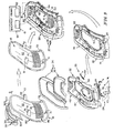
- Fig. 3 is an exploded perspective assembly view of illustrative components included in the seat back showing (from left to right) a backrest comprising three sheets included in the seat cover, the deformable back-support panel, a ring-shaped panel carrier underlying a cushion including a U-shaped portion of a pad and a U-shaped portion of a pad cover, and a backrest support comprising a backrest frame and a rear frame cover, and showing that the back-support panel-motion controller includes components cooperating to form the lower control unit in a lower dotted-line box and components cooperating to form the upper control unit in an upper dotted-lille box;
- Figs. 4-6 illustrate in sequence use of the passenger-controlled lower control unit in the back-support panel-motion controller to deform and otherwise change the shape of the back-support panel actively to establish a selected shape and therefore vary lumbar-support characteristics of the back-support panel to suit the passenger seated in the vehicle scat;
- Fig. 4 is an enlarged sectional view taken along line 4-4 of Fig. 2 showing the back-support panel in an initial position characterized by a fully bowed convex shape and showing illustrative components included in the lower and upper control units wherein the lower control unit includes a motorized gear system comprising a worm drive defined by a gear arrangement in which a worm (which is a gear in the form of a screw) meshes with a driven gear (which is similar in appearance to a spur gear);
- a motorized gear system comprising a worm drive defined by a gear arrangement in which a worm (which is a gear in the form of a screw) meshes with a driven gear (which is similar in appearance to a spur gear);
- Fig. 5 is a view similar to Fig. 4 showing the hack-support panel after it has been moved actively by the lower control unit to assume an intermediate position characterized by a partly bowed convex shape;
- Fig. 6 is a view similar to Figs. 4 and 5 showing the back-support panel after it has been moved actively by the lower control unit to assume a final position characterized by a concave shape;
- Figs. 7 and 8 illustrate passive control of motion of the back-support panel governed by yieldable springs included in each of the lower and upper control units of the hack-support panel-motion controller in response to application of movement-inducing forces applied to the deformable back-support panel by slouching smaller and larger passengers seated in the vehicle seat so that slouching or other movement of the passenger in the vehicle seat can change the shape of the deformable back-support panel temporarily without disabling or otherwise disrupting active control of back-support panel motion controller governed by a motorized gear system included in the lower control unit and operated by the passenger;
- Fig. 7 shows that a relatively small force (F SMALL ) is applied by the lumbar region of a back of a passenger seated in the vehicle seat when the passenger is of a relatively small size and slouches in the vehicle seat to cause a small deflection of each of the yieldable springs included in the lower and upper control units so as to vary the shape of the actively positioned deformable back-support panel temporarily from the selected shape (shown in phantom lines) established by operation of the lower control unit to a new shape (shown in solid lines) to suit the size and shape of the slouching smaller passenger;
- F SMALL relatively small force
- Fig. 8 shows that a relatively larger force (F LARGE ) is applied by the lumbar region of the back of a passenger seated in the vehicle seat when the passenger is of a relatively large size and slouches in the vehicle seat to cause a relatively larger deflection of the yieldable springs included in the lower and upper control units so as to vary the shape of the actively positioned deformable back-support panel temporarily from the selected shape (shown in phantom lines) established by operation of the lower control unit to a new shape (shown in solid lines) to suit the size and shape of the slouching larger passenger;
- F LARGE relatively larger force
- Fig, 9 shows various stages of assembly of components shown in Fig. 3 to produce the seat back shown in perspective in Figs. 1 and 2 and in section in Figs. 4-8 ;
- Fig.10 is an enlarged view of an illustrative lower control unit in accordance with another embodiment of the present disclosure.
- Fig. 11 is a view similar to Fig. 10 showing a lower control unit in accordance with two embodiments of the present disclosure wherein a link mover meshing with the driven gear is either a worm or a ratchet;
- Fig. 12 is a partial perspective assembly view of a scat back similar to the seat back shown in Figs. 1 and 2 made in accordance with an alternative construction;
- Fig. 13 is a sectional view of a portion of the seat back of Fig. 12 after the seat cover has been coupled to the back-support panel.
- a vehicle scat 10 includes a foundation 12 adapted to be anchored to a vehicle floor 13, a seat bottom 14 mounted on foundation 12, and a seat back 16 arranged to extend upwardly from seat bottom 14 and configured to include a passenger-controlled deformable back-support panel 18 as shown, for example, in Fig. 1 .
- a back-Support panel-motion controller 20 associated with seat back 16 is also included in vehicle seat 10 and is shown diagrammatically in Fig. and illustratively in Fig. 4 .
- Panel-motion controller 20 is configured to provide means operable by a passenger 11 seated in vehicle seat 10 for actively controlling motion of the deformable back-support panel 18 included in seat back 16 as suggested in Figs. 4-6 and for passively controlling motion of deformable back-support panel 18 as suggested in Figs. 7 and 8 .
- passenger 11 can change the shape of back-support panel 18 included in seat back 16 to provide a comfortable, customized, and sympathetic shape suited to the seated passenger 11.
- Back-support panel 18 is arranged to extend along the back of a passenger 11S or 11L seated in vehicle seat 10 to provide lumbar and other spinal column support for such a passenger as shown, for example, in Figs. 7 and 8 .
- Back-support panel 18 is made of a deformable construction and has a shape that can be varied at the option of the passenger to provide custom spinal column support suited to the needs and commands of each passenger 11S or 11L as suggested in Figs. 4-8 .
- Back-support panel 18 is configured to bend and flex in a designed way to ensure proper pressure distribution and support through a wide range of seated postures,
- back-support panel 18 is movable relative to a panel carrier 22 that is arranged to lie behind back-support panel 18 and is also included in seat back 16 as shown, for example, in Figs. 3 and 4 .
- Back-support panel 18 is also movable relative to a backrest support 30 located behind panel carrier 22 as suggested in Fig. 3 .
- back-support panel-motion controller 20 includes a lower control unit 24 coupled to lower portion 181. of back-support panel 18 and an upper control unit 26 coupled to upper portion 18U of back-support panel 18.
- lower control unit 24 provides both active and passive control of the shape of back-support panel 18 while upper control unit 26 provides only passive control of the shape of back-support panel 10.
- lower control unit 24 is configured to provide active-motion means for actively moving back-support panel 18 relative to panel carrier 22 and to backrest support 30 to cause the shape of back-support panel 18 to change to assume a selected shape so that lumbar support for a passenger 11 leaning against seat back 16 is varied to suit the seated passenger 11.
- Lower control unit 24 is also configured to provide lower passive-motion means for passively allowing shape-changing movement of back-support panel 18 relative to panel carrier 22 and to the backrest support 30 temporarily in response to rearwardly directed forces applied by the lumbar region of the back of a passenger 11 seated in vehicle seat 10 when the passenger 11 slouches or otherwise moves in a rearward direction as suggested in Fig. 7 in the case of a relatively smaller passenger 11 S and as suggested in Fig. 8 in the case of a relatively larger passenger 11L.
- upper control unit 26 is configured to provide upper passive-motion means for passively allowing shape-changing movement of hack-support panel 18 relative to panel carrier 22 and to backrest support 30 in response to rearwardly directed forces applied by a relatively smaller passenger 11S as suggested in Fig. 7 and a relatively larger passenger 11L as suggested in Fig. 8 .
- Upper control unit 26 is separated from and operates independently of lower control unit 24.
- Back-support panel 18 is defined by a thin pliable contoured comfort shell made of a pliable plastics material in an illustrative embodiment as suggested in Figs. 3 and 4-8 .
- Lower portion 18L of back-support panel 18 is formed 10 include a series of generally horizontal extending slots 19 in an illustrative embodiment shown in Figs. 1-4 .
- Slots 19 are formed to lie in vertically spaced-apart parallel relation to one another. Slots 19 are sized and shaped to facilitate controlled deformation of lower portion 18L of back-support panel 18 under the control of lower control unit 24 of panel-motion controller 20 as suggested in Figs. 4-8 .
- upper portion 18U is also configured to deform and change shape (1) during motor-driven active movement of lower portion 18L under the control of lower control unit 24 as shown, for example, in Figs. 4-6 and (2) during passenger-driven passive movement of lower portion 18L and/or upper portion 18U in response to application of rearward movement-inducing forces F SMALL , F LARGE applied by seated passengers US, 11L to load a yieldable spring 77 included in lower control unit 24 and/or yieldable springs 96 included in upper control unit 26 as shown, for example, in Figs. 7 and 8 .
- Seat back 16 includes a backrest 28 and a Backrest support 30 in the illustrative embodiment shown, for example, in rigs. 1-3.
- back-support panel-motion controller 20 is coupled to backrest 28 and backrest support 30 as suggested in Fig. 3 and 9 so that panel-motion controller 20 is arranged to control active and passive motion of back-support panel 18 as suggested in Figs. 4-6 , 7, and 8 .
- Backrest 28 includes at seat cover 32, deformable hack-support panel 18, panel carrier 22, and a cushion 34 comprising a pad 36 and a pad cover 38 as shown, for example, in Fig. 3 .
- Panel carrier 22 is ring-shaped in the illustrated embodiment and arranged to lie behind back-support panel 18 as suggested in Fig. 3 .
- Pad 36 is sized to fit into a pad-receiving space 40 formed in an upper portion 42 of panel carrier 22 as also suggested in Fig. 3 .
- Pad cover 38 is configured to cover pad 36 and portions of panel carrier 22 and he coupled to panel carrier 22 as suggested in Figs. 3 and 9 .
- Seat cover 32 includes first, second, and third sheets 321, 322, and 323 as suggested in Figs. 2 and 3 in an illustrative embodiment.
- First sheet 321 is a trim cover.
- Second sheet 322 is a foam backer.
- Third sheet 323 is a cushion foam pad. Any suitable means may he used to couple seat cover 32 to deformable hack-support panel 18.
- One example of a seat cover coupling is illustrated in Figs. 12 and 13 .
- Panel carrier 22 includes a lower portion 44 formed to include an H-shaped elongated lower-controller mount slot 46 and first and second upper-controller mount slots 47, 48 as suggested in Fig. 3 .
- Portions of lower control unit 24 are arranged to extend through H-shaped elongated lower-controller mount slot 46 when panel-motion controller 20 is coupled to backrest support 30 as suggested in Fig. 3 .
- Portions of upper control unit 26 are arranged to extend through each of first and second upper-controller mount slots 47, 48 when panel-motion controller 20 is coupled to backrest support 30 as also suggested in Fig. 3 .
- Slots 47, 48 are arranged to lie between pad-receiving space 40 and slot 46 as shown, for example, in Pig. 3.
- Panel carrier 22 is also formed to include a large central aperture 50 as suggested in Fig. 3 .
- Deformable back-support panel 18 is arranged to cover a front side of central aperture 50 as suggested in Figs. 3 and 9 .
- a rearwardly facing surface 52 on back-support panel 18 is visible through central aperture 50 as suggested in Fig. 9 .
- Backrest support 30 includes a backrest frame. 54 and a rear frame cover 56 in an illustrative embodiment as shown, for example, in Fig. 3 .
- Backrest frame 54 is arranged to lie between panel carrier 22 and rear frame cover 56.
- Panel carrier 22 is coupled to Backrest frame 54 to support backrest 28 in an anchored position on backrest support 30 and to allow movement of back-support panel 18 relative to backrest frame 54.
- Backrest frame 54 is a rigid unit configured to be mounted on foundation 12 in a stationary position relative to vehicle flour 13 as suggested in Figs. 1 and 9 .
- Backrest frame 54 is formed to include a central aperture 60 as suggested in Fig. 3 .
- Central aperture; 60 is flanked by first and second upright mount strips 61, 62 as shown, for example, in Fig. 3 .
- Upper control unit 26 is coupled to first and second upright mount : strips 61, 62 as suggested in the illustrative embodiment shown in Fig. 3 .
- Rear frame cover 56 is configured to mount on and cover a rear side of backrest frame 54 as suggested in Fig. 3 .
- Rear frame cover 56 includes a ring-shaped shield 64 formed to include a central aperture 66 and a ring-shaped wall 68 coupled to shield 64 along an interior perimeter edge thereof defining central aperture 66.
- Ring-shaped wall 68 is arranged to extend in a forward direction through central aperture 60 of backrest fame 54 and central aperture 50 of panel carrier 22 when rear frame cover 56 and panel carrier 22 are coupled to backrest frame 54 as suggested in Fig. 3 .
- Rearwardly facing surface 52 of back-support panel 18 will he visible through central apertures 50, 60, and 66 as suggested in Fig. 3 when seat hack 16 is assembled.
- central aperture 66 it is within the scope of this disclosure to install a panel (not shown) in central aperture 66 to close that aperture for aesthetic reasons if desired, It is also within the scope of the present disclosure to mount a map pocket or a floating mesh pocket in central aperture 66 so as to be accessible to a passenger seated in a scat (not shown) located behind vehicle seat 10.
- lower control unit 24 of panel-motion controller 20 includes laterally spaced-apart first and second lower panel mount 71, 72, a link mover 70, and a shape-control link 74 coupled at one end to lower panel mounts 71, 72 and at another end to link mover 70 as suggested in Figs. 3 and 4 .
- Link mover 70 is configured to provide means for moving shape-control link 74 relative to panel carrier 22 and to backrest support 30 to cause movement of lower portion 18L of back-support panel 18 relative to panel carrier 22 and to backrest support 30 so that the shape of back-support panel 18 is changed to suit passenger 11 seated in vehicle seat 10 as shown, for example, in Figs. 4-6 .
- link mover 70 is coupled to backrest frame 54 of backrest support 30 or to another suitable structure near backrest 28.
- Lower panel mounts 71, 72 are coupled to rearwardly facing surface 52 of back-support panel 18 and arranged to lie in spaced-apart relation to one another and extend rearwardly toward backrest support 30 as suggested in Figs. 3 and 9 .
- shape-control link 74 is arranged to extend through H-shaped elongated lower-controller mount slot 46 as suggested in Fig. 3 and one end of shape-control link 74 is coupled to each of first and second lower panel mounts 71, 72 as suggested in Figs. 3 and 9 .
- Shape-control link 74 includes an input block 76 coupled to link mover 70, an output block 78 coupled to lower panel mount 71 (and lower panel mount 72) using an axle rod 75 sized to extend into apertures formed in lower panel mounts 71, 72 and into apertures formed in output block 78, and a yieldable spring 77 made of an elastic material and arranged to interconnect input block 76 and output block 78 as suggested in Fig. 4 .
- An illustrative input block 76 comprises a clamp 80 coupled to one end of spring 77, a driven gear 82, and a pivot rod 84 coupled to clamp 80 and driven gear 82 to retain driven gear 82 in a fixed position relative to clamp 80.
- An illustrative output block 78 is shown in Figs.
- Shape-control link 74 also includes two mount brackets 73A, 7313 as shown, for example, in Fig. 3 and these brackets 73A, 73B arc coupled to backrest frame 54.
- a shape-control link 174 comprising a clock spring 177 in accordance with another embodiment of the present disclosure is shown in Fig. 10 .
- An illustrative lower control unit 24 of the type shown in Figs. 3-9 includes a motorized gear system comprises a worm drive defined by a gear arrangement in which a worm 86 (which is a gear in the form of a screw) meshes with a driven gear 82 (which is similar in appearance to a spur gear) is shown in Fig. 4 .
- Link mover 70 includes a worm 86 configured to mate with driven gear 82, a motor 88 configured to provide means for rotating worm 86 about an axis of rotation 89, and a motor actuator 90 coupled to motor 88 and configured to actuate motor 88 at the command of passenger 11 in vehicle seat 10 in an illustrative embodiment shown, for example, in Fig. 4 .
- Worm 86 is configured to mesh with teeth included in driven gear 82 so as to cooperate with driven gear 82 to establish a worm drive.
- rotation of worm 86 about axis of rotation 89 moves driven gear 82 from a horizontal position shown, for example, in Fig. 4 through an angle O of about 20° to assume a first inclined position shown, for example, in Fig. 5 and through an angle ⁇ of about 33° to assume a relatively steeper second inclined position shown, for example, in Fig. 6 so as to move shape-control link 74 to cause the shape of deformable back-support panel 18 to change.
- driven gear 82 rotates in direction 200 about pivot rod 84
- spring 77 is loaded to cause output block 78 to move to cause back-support panel 18 to change shape from a fully bowed convex shape as shown in Fig. 4 to an intermediate position characterized by a partly bowed convex shape, as shown in Fig. 5 and then to a final position characterized by a concave shape.
- upper control unit 26 of panel-motion controller 20 includes laterally spaced-apart first and second upper panel mounts 91, 92 and first and second shape-control links 93, 94 as shown, for example, in Fig. 3 .
- Shape-control link 93 is coupled at one end to first upper panel mount 91 and at another end to panel carrier 22 and to backrest frame 54 of backrest support 30 as suggested in Figs. 3 and 4 .
- shape-control link 94 is coupled at one end to second upper panel mount 92 and at another end to strip 92 of panel carrier 22 and to backrest frame 54 as suggested in Fig. 3 .
- Each of shape-control links 93, 94 includes a spring 96 comprising, in series, first segment 961, second segment 962 and third segment 963.
- Shape-control link 94 also includes a fastener 97 coupled to first segment 961 and to panel carrier 22 (and to backrest frame 54) to anchor spring 96 to panel carrier 22 (and to backrest frame 54) and allow movement of second and third segments 962, 963 relative to panel carrier 22 (and to backrest frame 54) as suggested in Figs. 7 and 8 .
- Each of shape-control links 93, 94 also includes a connector 98 coupled to a companion third segment 963 and arranged to straddle a slot 99 formed in that companion third segment 963 as suggested in Fig. 3 .
- First upper panel mount 91 is arranged to extend through first upper-controller mount slot 47 to mate with connector 98 included in a companion first shape-control link 93 or upper control unit 26 as suggested in Figs. 3 and 4 .
- a companion connector 98 extends into a notch 111 formed in first upper panel mount 91 while a free end of first upper panel mount 91 extends through slot 99 formed in third segment 963 of spring 96 of first shape-control link 93 as suggested in Fig. 4 .
- second upper panel mount 92 is arranged to extend through second upper-controller mount slot 48 to mate with connector 98 included in a companion second shape-control link 94 of upper control unit 26 as suggested in Fig. 3 .
- a companion connector 98 extends into a notch 112 formed in second upper panel mount 92 while a free end of second upper panel mount 92 extends through slot 99 formed in third segment 963 of spring 96 of second shape-control link 94 as suggested in Fig. 3 .
- a sequence of use of lower control unit 24 in back-support panel-motion controller 20 to deform and otherwise change the shape of back-support panel 18 actively to vary lumbar-support characteristics of back-support panel 18 to assume a selected shape to suit the passenger 11 seated in vehicle seat 10 is shown, for example, in Figs. 4-6 .
- Back-support panel 18 is shown, for example, in Figs. 2 and 4 in an initial position characterized by a fully bowed convex shape.
- Back-support panel 18 is shown in Fig. 5 after it has been moved actively by lower control unit 24 to assume an intermediate position characterized by a partly bowed convex shape.
- hack-support panel 18 is shown in Fig. 6 after it has been moved actively by lower control unit 24 to assume a final position characterized by a concave shape.
- This spring-regulated system allows slouching or other movement of the passenger 11S or 11L in vehicle seat 10 to change temporarily the shape of deformable back-support panel 18 from the selected shape established by lower control unit 24 without disabling or otherwise disrupting active control of back-support panel motion controller 20 governed by a motorized gear system comprising driven gear 86, motor 88, and motor actuator 90 included in lower control unit 24 and operated by passenger 11 S or 11 L.
- F SMALL relatively small force
- F SMALL relatively small force
- passenger 11S is of a relatively small size and slouches in vehicle seat 10 to cause a small deflection of each of springs 77,96 included in lower and upper control units 24, 26 so as to vary the shape of the actively positioned deformable back-support panel 18 temporarily to suit the size and shape of the slouching smaller passenger 11S as suggested in Fig. 7 .
- a relatively larger force (F LARGE ) is applied by the lumbar region of the back of a passenger 11L seated in vehicle seat 10 when passengers 11 L is of a relatively large size and slouches in vehicle seat 10 to cause a relatively larger defection of springs 77, 96 included in lower and upper control units 24, 26 so as to vary passively the shape of the actively positioned deformable back-support panel 18 temporarily to suit the size and shape of the slouching larger passenger 11L as suggested in Fig. 8 .
- shape-control link 174 include an input block 182 (e.g., driven gear) coupled to link mover 70, an output block 178 coupled to lower panel mount 71 (and lower panel mount 72) using an axle rod 75 sized to extend into apertures formed in lower panel mounts 71, 72 and into apertures formed in output block 178, and a yieldable spring 177 arranged to interconnect input block 182 and output block 178.
- Spring 177 is a spiral clock spring in an illustrative embodiment as shown in Fig. 10 .
- output block 178 is a bar that includes a first member 178A coupled to pivot rod 184 and a second member 178B coupled to axle rod 75 and arranged to define an obtuse included angle 148 of about 148 degrees therebetween as shown in Fig. 10 .
- clock spring 177 is expanded to cause shape-control link 174 to move to cause back-support panel 18 to change shape from a fully bound convex shape as shown in Fig. 10 (see also Fig. 4 ) to assume a final position characterized by a concave shape (of the type shown, for example, in Fig. 6 ).
- Fig. 11 is a view similar to Fig. 10 showing a lower control unit in accordance with two embodiments of the present disclosure wherein the link mover meshing with driven gear 82 is either a worm 86 or a ratchet 186. It is within the scope of the present disclosure to use any suitable means to rotate driven gear 82 about pivot rod 84 to load or unload a spring (e.g. 77 or 177) to cause back-support panel 18 to change shape.
- a spring e.g. 77 or 177
- FIG. 12 A partial perspective assembly view of a seat back similar to the scat back shown in Figs, 1 and 2 made in accordance with an alternative construction is shown in Fig. 12 .
- FIG. 13 A sectional view of a portion of the seat back of Fig. 12 after the seat cover has been coupled to the back-support panel is shown in Fig. 13 .
- a back-support panel 11 R is formed to include two horizontally extending ridge-retainer grooves 201, 202 extending across the width of back-support panel 118 as shown in Figs. 12 and 13 .
- First ridge-retainer groove 201 provides an opening in a forwardly facing surface 211 of hack-support panel 118.
- Second ridge-retainer groove 202 provides an opening in a rearwardly facing surface 212 of back-support panel 118.
- Each groove 201,202 is arranged to lie a predetermined distance below a laterally extending top surface 213 of hack-support panel 118 as suggested in Fig. 12 .
- a portion of an illustrative seat cover 132 in accordance with another embodiment, of the present disclosure includes a sheet 134 including first, second, and third panels 135, 136, 137 folded as suggested in " Fig. 12 and a clamp 133 as also suggested in Fig. 12 .
- Sheet 134 is coupled to clamp 133 as suggested in Fig. 13 and clamp 133 is adapted to mate with back-support panel 118 as suggested in Figs. 12 and 13 to mount sheet 134 on hack-support panel 118.
- Clamp 133 includes first and second side walls 137, 139, a top wall interconnnecting top edges of first and second side walls 137, 139, a first ridge 141 coupled to a lower edge of first side wall 137, and a second ridge 142 coupled to a lower edge of second side wall 139.
- First ridge 141 is configured to extend into first ridge-retainer groove 201 and second ridge 142 is arranged to extend toward first ridge 141 and into second ridge-retainer groove 202 to anchor clamp 138 to back-support panel 118 as suggested in Fig. 13 .
- Panels 136, 137 of sheet 134 arc folded to form a strip that is coupled to second side wall 139 of clamp 133 using any suitable means.
- Panel-motion controller 20 provides means for controlling a comfort shell defined by back-support panel 18 included in an automotive seat structure such as vehicle seal 10.
- Back-support panel 18 is a molded plastic seat pan with a sympathetic shape to the occupant of vehicle seat 10.
- Back-support panel 18 is configured to bend and flex in a designed way to ensure proper pressure distribution and support through a wide range of seated postures.
- back-support panel 18 The shape of the comfort shell established by back-support panel 18 is controlled in part by lower control unit 24 located behind back-support panel 18 and coupled to rearwardly facing surface 52 of back-support panel 18 and to backrest support 30. Such shape is also controlled in part by upper control unit 26 also located behind back-support panel 18 and coupled to rearwardly facing surface 52 of back-support panel 18 and to backrest support 30.
- Each unit 24, 26 includes either a spring extending across the width of back-support panel 18 or independent left and right springs.
- lower and upper control units 24,26 are located behind back-support panel 18, i.e., between back-support panel 18 and backrest support 30 in a manner suited for use in a vehicle scat so as not to expand the dimensions of the vehicle seat and to function without impeding ingress/egress.
- Upper control unit 26 is configured to combine with back-support panel 18 to provide upper back performance to satisfy dynamic driving conditions associated with vehicles.
- a spinal column of a passenger 11 includes (from top to bottom in series) cervical, thoracic, lumbar, sacral, and coccyx regions.
- the lumbar region of the spine is characterized normally by a lordotic curve described as convex anteriorly and concave posteriorly.
- the spine could shift so as to be characterized by a kyphotic curve described as concave anteriorly and convex posteriorly.
- Back-support Panel 18 and panel-motion controller 20 are configured in accordance with the present disclosure to vary the shape of back-support panel 18 in one or both of active and reactive (passive) modes of operation under the command and control of a seated passenger 11.
- Back-support panel 18 is varied in shape owing in part to passenger motion-driven deflection of clastic yieldable springs 77, 96 in lower and upper control units 24, 26 of panel-motion controller 20 to provide customized upper back deflection (sinking feeling) to suit the needs of a slouching passenger large or small (11L or 11S) as suggested in Figs. 7 and 8 .
- Back-.support panel 18 is also varied in shape owing in part to motor-driven movement of link 74 in lower control unit 24 to provide posture adjustment (lordosis to kyphosis) to suit the needs of a passenger 11 seated in vehicle seat 10 as suggested in Figs. 4-6 .
- Each of these shape-varying inputs can occur in isolation or combination and cooperate in an additive manner to vary the shape of back-support panel 18 to suit the needs of passenger 11.
- Deformable back-support panel 18 is configured to bend and flex to move relative to backrest support 30 to assume many different shapes to provide custom spinal column support to a passenger seated in vehicle scat 10 adjacent to deformable back-support panel 18.
- Back-support panel-motion controller 20 is coupled to deformable back-support panel 18.
- Back-support panel-motion controller 20 is configured to provide means (operable by a passenger seated in vehicle scat 10) for moving deformable back-support panel 18 relative to backrest support 30 in an initial stage of active operation to assume a selected shape in response to activation of an actuator included in hack-support panel-motion controller 20 and for independently allowing the selected shape of deformable back-support panel 18 to vary passively after assumption of the selected shape in a subsequent stage of passive operation without activating the actuator in response to forces applied by a torso of a seated passenger leaning against deformable back-support panel 18 as the seated passenger shifts position relative to scat back 16 to assume a new posture in vehicle seat 10.
- Deformable back-support panel 18 includes an upper portion 18U arranged to lie in spaced-apart relation to seat bottom 14 and a lower portion 18L arranged to lie between seat bottom 14 and upper portion 180.
- Back-support panel-motion controller 20 includes a lower control unit 24 coupled to lower portion 18L of deformable back-support panel 18 and configured to provide active-motion means for actively moving deformable back-support panel 18 relative to backrest support 30 to cause the shape of deformable back-support panel 18 to change to assume the selected shape so that lumbar support for a seated passenger leaning against seat back 16 is varied to suit the passenger and to provide lower passive-motion means for passively allowing shape-changing movement of deformable back-support panel 18 temporarily away from the selected shape and relative to backrest support 30 in response to rearwardly directed forces applied by a seated passenger during a shift in position of the seated passenger on seat bottom 14 and relative to seat back 16 to assume a new posture in vehicle seat 10.
- Lower control unit 24 includes a lower panel mount 71 coupled to lower portion 18L of deformable back-support panel 18, a link mover 70 separated from deformable back-support panel 18, and a shape-control link (74 or 174) arranged to interconnect lower panel mount 72 and link mover 70.
- Link mover 70 is configured to provide means for actively moving the shape-control link. (74 or 174) relative to backrest support 30 to cause movement of lower portion 18L of deformable back-support panel 18 relative to backrest support 30 so that the shape of deformable back-support panel 18 is varied to assume the selected shape to suit the seated passengers.
- Shape-control link 74 (or 174) comprises a yieldable spring 77 (or 177) made of an elastic material.
- the shape-control link is configured to yield elastically when deformable back-support panel 18 has assumed the selected shape during exposure of deformable back-support panel 18 to rearwardly directed forces applied by the seated passenger during a change in posture of the seated passenger to allow deformable back-support panel 18 to assumed temporarily a changed shape only as long as the rearwardly directed forces are applied to deformable back-support panel 18 by the seated passenger.
- Back-support panel-motion controller 20 further includes an upper control unit 26 coupled to upper portion 18U of deformable block-support panel 18.
- Upper control unit 26 is configured to provide passive-motion means for passively allowing shape-changing movement of deformable back-support panel 18 relative to backrest support 30 temporarily in response to rearwardly directed forces applied by a lumbar region of a back of a seated passenger when the person slouches to move in a rearward direction toward deformable back-support panel 18.
- Upper control unit 26 includes an upper panel mount 91 coupled to upper portion 18U of deformable back-support panel 18 and a shape-control link 93 coupled to upper panel mount 91.
- Shape-control link 93 is configured to include a yieldable spring 96 made of an elastic material and configured to yield elastically in response to application of movement-inducing forces applied to deformable back-support panel 18 by a seated passenger during a change in posture of the seated passenger.
- Seat back 16 further includes a panel carrier 22 interposed between deformable back-support panel 18 and backrest support 30 and formed to include an opening.
- a lower portion of back-support panel-motion controller 20 is arranged to interconnect backrest support 30 and deformable back-support panel 18 and extend through the opening formed in panel carrier 22 and an upper portion of back-support panel-motion controller 20 is arranged to interconnect deformable back-support panel 18 and panel carrier 22.
- Upper portion of back-support panel-motion controller 20 is coupled to upper portion 18U of deformable back-support panel 18, Lower portion of back-support panel-motion controller 20 is coupled to the lower portion of deformable back-support panel 20.
Applications Claiming Priority (1)
| Application Number | Priority Date | Filing Date | Title |
|---|---|---|---|
| US26364209P | 2009-11-23 | 2009-11-23 |
Publications (2)
| Publication Number | Publication Date |
|---|---|
| EP2325040A1 true EP2325040A1 (fr) | 2011-05-25 |
| EP2325040B1 EP2325040B1 (fr) | 2018-01-03 |
Family
ID=43597781
Family Applications (1)
| Application Number | Title | Priority Date | Filing Date |
|---|---|---|---|
| EP10014831.1A Active EP2325040B1 (fr) | 2009-11-23 | 2010-11-22 | Coque de confort contrôlable pour siège de véhicule |
Country Status (3)
| Country | Link |
|---|---|
| US (2) | US8857908B2 (fr) |
| EP (1) | EP2325040B1 (fr) |
| ES (1) | ES2663636T3 (fr) |
Cited By (5)
| Publication number | Priority date | Publication date | Assignee | Title |
|---|---|---|---|---|
| WO2015086765A1 (fr) * | 2013-12-13 | 2015-06-18 | Johnson Controls Gmbh | Partie de siège et siège de véhicule |
| WO2018033479A1 (fr) * | 2016-08-18 | 2018-02-22 | Recaro Aircraft Seating Gmbh & Co. Kg | Dispositif de siège d'avion |
| WO2018050603A1 (fr) * | 2016-09-19 | 2018-03-22 | Isringhausen Gmbh & Co. Kg | Dossier de siège, en particulier de siège de véhicule |
| CN110901476A (zh) * | 2019-10-31 | 2020-03-24 | 广州市甬利格宝信息科技有限责任公司 | 一种智能调节车载座椅及其使用方法 |
| DE102014201125B4 (de) | 2013-01-24 | 2024-02-22 | Ford Global Technologies, Llc | Flexibles Fahrzeugsitzfederungssystem |
Families Citing this family (102)
| Publication number | Priority date | Publication date | Assignee | Title |
|---|---|---|---|---|
| US9022475B2 (en) | 2010-11-11 | 2015-05-05 | Faurecia Automotive Seating, Inc. | Compliant shell for vehicle seat |
| US9096147B2 (en) * | 2011-09-12 | 2015-08-04 | Faurecia Automotive Seating, Llc | Controllable comfort shell for vehicle seat |
| EP2760702B1 (fr) * | 2011-09-26 | 2018-09-05 | Faurecia Automotive Seating, LLC | Dossier de siège de véhicule à commande de mouvement à raccord flexible |
| DE102011055286A1 (de) * | 2011-10-17 | 2013-04-18 | Grammer Ag | Fahrzeugsitz, insbesondere Schienenfahrzeugsitz, mit einem Polsterelementbefestigungsrahmen |
| WO2014024859A1 (fr) * | 2012-08-07 | 2014-02-13 | テイ・エス テック株式会社 | Structure de fixation d'élément et siège de véhicule |
| JP6088795B2 (ja) * | 2012-10-31 | 2017-03-01 | 東海旅客鉄道株式会社 | 乗物用の座席 |
| US9902293B2 (en) | 2013-01-24 | 2018-02-27 | Ford Global Technologies, Llc | Independent cushion extension with optimized leg-splay angle |
| US9415713B2 (en) | 2013-01-24 | 2016-08-16 | Ford Global Technologies, Llc | Flexible seatback system |
| US9399418B2 (en) | 2013-01-24 | 2016-07-26 | Ford Global Technologies, Llc | Independent cushion extension and thigh support |
| US9193284B2 (en) | 2013-06-11 | 2015-11-24 | Ford Global Technologies, Llc | Articulating cushion bolster for ingress/egress |
| EP3017997B1 (fr) * | 2013-07-04 | 2018-03-21 | Delta Tooling Co., Ltd. | Mécanisme de commande d'opération de rotation et siège |
| US9527418B2 (en) | 2013-09-12 | 2016-12-27 | Ford Global Technologies, Llc | Semi rigid push/pull vented envelope system |
| US9187019B2 (en) | 2013-10-17 | 2015-11-17 | Ford Global Technologies, Llc | Thigh support for customer accommodation seat |
| US9505322B2 (en) | 2013-10-25 | 2016-11-29 | Ford Global Technologies, Llc | Manual lumbar pump assembly |
| PL226831B1 (pl) * | 2013-10-28 | 2017-09-29 | Maciej Szymański | Sposób wytwarzania pokrycia tapicerskiego, zwłaszcza foteli pojazdów komunikacji zbiorowej ipokrycie tapicerskie, zwłaszcza foteli pojazdów komunikacji zbiorowej |
| US9566884B2 (en) | 2013-11-11 | 2017-02-14 | Ford Global Technologies, Llc | Powered head restraint electrical connector |
| JP6202734B2 (ja) * | 2013-11-18 | 2017-09-27 | 株式会社タチエス | シート |
| JP6192221B2 (ja) * | 2013-11-18 | 2017-09-06 | 株式会社タチエス | シート |
| US9365143B2 (en) | 2013-12-12 | 2016-06-14 | Ford Global Technologies, Llc | Rear seat modular cushion |
| US9315131B2 (en) | 2014-01-23 | 2016-04-19 | Ford Global Technologies, Llc | Suspension seat back and cushion system having an inner suspension panel |
| US9649963B2 (en) * | 2014-03-04 | 2017-05-16 | Ford Global Technologies, Pllc | Trim and foam assembly for a vehicle seat |
| US9527419B2 (en) | 2014-03-31 | 2016-12-27 | Ford Global Technologies, Llc | Vehicle seating assembly with manual cushion tilt |
| US9421894B2 (en) | 2014-04-02 | 2016-08-23 | Ford Global Technologies, Llc | Vehicle seating assembly with manual independent thigh supports |
| US9302643B2 (en) | 2014-04-02 | 2016-04-05 | Ford Global Technologies, Llc | Vehicle seating assembly with side airbag deployment |
| US9694741B2 (en) | 2014-08-25 | 2017-07-04 | Ford Global Technologies, Llc | Ambient functional lighting of a seat |
| US10471874B2 (en) | 2014-09-02 | 2019-11-12 | Ford Global Technologies, Llc | Massage bladder matrix |
| US9333882B2 (en) | 2014-10-03 | 2016-05-10 | Ford Global Technologies, Llc | Manual upper seatback support |
| US9776533B2 (en) | 2014-10-03 | 2017-10-03 | Ford Global Technologies, Llc | Torsion bar upper seatback support assembly |
| US9789790B2 (en) | 2014-10-03 | 2017-10-17 | Ford Global Technologies, Llc | Tuned flexible support member and flexible suspension features for comfort carriers |
| US9771003B2 (en) | 2014-10-29 | 2017-09-26 | Ford Global Technologies, Llc | Apparatus for customizing a vehicle seat for an occupant |
| US9517777B2 (en) | 2014-11-06 | 2016-12-13 | Ford Global Technologies, Llc | Lane departure feedback system |
| US9340131B1 (en) | 2014-11-06 | 2016-05-17 | Ford Global Technologies, Llc | Head restraint with a multi-cell bladder assembly |
| US10065570B2 (en) | 2014-12-10 | 2018-09-04 | Ford Global Technologies, Llc | Electronic device holder for a vehicle seat |
| US9593642B2 (en) | 2014-12-19 | 2017-03-14 | Ford Global Technologies, Llc | Composite cam carrier |
| KR101784472B1 (ko) * | 2015-01-13 | 2017-10-11 | 주식회사 씨케이머티리얼즈랩 | 촉각 정보 제공 기기 |
| US9663000B2 (en) | 2015-01-16 | 2017-05-30 | Ford Global Technologies, Llc | Vehicle seat configured to improve access |
| US9365142B1 (en) | 2015-01-20 | 2016-06-14 | Ford Global Technologies, Llc | Manual independent thigh extensions |
| US9707877B2 (en) | 2015-01-20 | 2017-07-18 | Ford Global Technologies, Llc | Independent thigh extension and support trim carrier |
| DE102016100873A1 (de) * | 2015-01-29 | 2016-08-04 | Ford Global Technologies, Llc | Flexibles Rückenlehnensystem |
| US10011205B2 (en) * | 2015-02-11 | 2018-07-03 | Ford Global Technologies, Llc | Value assembly for seatbacks and cushions |
| US9622570B1 (en) | 2015-02-13 | 2017-04-18 | Steelcase Inc. | Personal workspace assembly |
| US9566930B2 (en) * | 2015-03-02 | 2017-02-14 | Ford Global Technologies, Llc | Vehicle seat assembly with side-impact airbag deployment mechanism |
| US9802535B2 (en) * | 2015-04-27 | 2017-10-31 | Ford Global Technologies, Llc | Seat having ambient lighting |
| US10046682B2 (en) * | 2015-08-03 | 2018-08-14 | Ford Global Technologies, Llc | Back cushion module for a vehicle seating assembly |
| US9718387B2 (en) | 2015-08-03 | 2017-08-01 | Ford Global Technologies, Llc | Seat cushion module for a vehicle seating assembly |
| WO2017022493A1 (fr) * | 2015-08-04 | 2017-02-09 | テイ・エス テック株式会社 | Siège de véhicule |
| US9688174B2 (en) | 2015-08-07 | 2017-06-27 | Ford Global Technologies, Llc | Multi-cell seat cushion assembly |
| US9573528B1 (en) | 2015-08-25 | 2017-02-21 | Ford Global Technologies, Llc | Integrated seatback storage |
| JP6582836B2 (ja) * | 2015-10-01 | 2019-10-02 | トヨタ紡織株式会社 | 乗物用シート |
| JP6582835B2 (ja) * | 2015-10-01 | 2019-10-02 | トヨタ紡織株式会社 | 乗物用シート |
| US9616776B1 (en) | 2015-11-16 | 2017-04-11 | Ford Global Technologies, Llc | Integrated power thigh extender |
| US9809131B2 (en) | 2015-12-04 | 2017-11-07 | Ford Global Technologies, Llc | Anthropomorphic pivotable upper seatback support |
| US9931999B2 (en) | 2015-12-17 | 2018-04-03 | Ford Global Technologies, Llc | Back panel lower clip anchorage features for dynamic events |
| US10093214B2 (en) | 2016-01-14 | 2018-10-09 | Ford Global Technologies, Llc | Mechanical manual leg tilt |
| US9914421B2 (en) | 2016-01-15 | 2018-03-13 | Ford Global Technologies, Llc | Seatback flexible slip plane joint for side air bag deployment |
| US9776543B2 (en) | 2016-01-25 | 2017-10-03 | Ford Global Technologies, Llc | Integrated independent thigh supports |
| US10052990B2 (en) | 2016-01-25 | 2018-08-21 | Ford Global Technologies, Llc | Extended seatback module head restraint attachment |
| US9756408B2 (en) | 2016-01-25 | 2017-09-05 | Ford Global Technologies, Llc | Integrated sound system |
| US10035442B2 (en) | 2016-01-25 | 2018-07-31 | Ford Global Technologies, Llc | Adjustable upper seatback module |
| US10046681B2 (en) | 2016-04-12 | 2018-08-14 | Ford Global Technologies, Llc | Articulating mechanical thigh extension composite trim payout linkage system |
| US10286818B2 (en) | 2016-03-16 | 2019-05-14 | Ford Global Technologies, Llc | Dual suspension seating assembly |
| US9849817B2 (en) | 2016-03-16 | 2017-12-26 | Ford Global Technologies, Llc | Composite seat structure |
| US9994135B2 (en) | 2016-03-30 | 2018-06-12 | Ford Global Technologies, Llc | Independent cushion thigh support |
| US10220737B2 (en) | 2016-04-01 | 2019-03-05 | Ford Global Technologies, Llc | Kinematic back panel |
| US9889773B2 (en) * | 2016-04-04 | 2018-02-13 | Ford Global Technologies, Llc | Anthropomorphic upper seatback |
| US20170291524A1 (en) * | 2016-04-11 | 2017-10-12 | Lear Corporation | Comfort system for seating backs with reduction in pur volume and environmentally friendly construction |
| US9802512B1 (en) | 2016-04-12 | 2017-10-31 | Ford Global Technologies, Llc | Torsion spring bushing |
| US10081279B2 (en) | 2016-04-12 | 2018-09-25 | Ford Global Technologies, Llc | Articulating thigh extension trim tensioning slider mechanism |
| US10625646B2 (en) | 2016-04-12 | 2020-04-21 | Ford Global Technologies, Llc | Articulating mechanical thigh extension composite trim payout linkage system |
| US10021985B2 (en) * | 2016-04-28 | 2018-07-17 | James E. Grove | Adjustable back support assembly for the back of a chair |
| DE102016212387A1 (de) | 2016-05-27 | 2017-11-30 | Lear Corporation | Sitz-Stützschichtanordnung |
| US9845029B1 (en) | 2016-06-06 | 2017-12-19 | Ford Global Technologies, Llc | Passive conformal seat with hybrid air/liquid cells |
| US9834166B1 (en) | 2016-06-07 | 2017-12-05 | Ford Global Technologies, Llc | Side airbag energy management system |
| US9849856B1 (en) | 2016-06-07 | 2017-12-26 | Ford Global Technologies, Llc | Side airbag energy management system |
| US10463153B2 (en) * | 2016-06-09 | 2019-11-05 | Steelcase Inc. | Seating arrangement |
| US10166895B2 (en) | 2016-06-09 | 2019-01-01 | Ford Global Technologies, Llc | Seatback comfort carrier |
| US10166894B2 (en) | 2016-06-09 | 2019-01-01 | Ford Global Technologies, Llc | Seatback comfort carrier |
| US10377279B2 (en) | 2016-06-09 | 2019-08-13 | Ford Global Technologies, Llc | Integrated decking arm support feature |
| US10220745B2 (en) | 2016-08-05 | 2019-03-05 | Ford Global Technologies, Llc | Inner carrier substrate trim cover attachment |
| US10220750B2 (en) | 2016-08-05 | 2019-03-05 | Ford Global Technologies, Llc | Inner carrier substrate mechanical lock with head restraint guide sleeves |
| US9845032B1 (en) | 2016-08-05 | 2017-12-19 | Ford Global Technologies, Llc | Modular back panel sub-assembly |
| US10011204B2 (en) * | 2016-08-05 | 2018-07-03 | Ford Global Technologies, Llc | Molded soft back panel |
| US10286824B2 (en) | 2016-08-24 | 2019-05-14 | Ford Global Technologies, Llc | Spreader plate load distribution |
| US10279714B2 (en) | 2016-08-26 | 2019-05-07 | Ford Global Technologies, Llc | Seating assembly with climate control features |
| US10391910B2 (en) | 2016-09-02 | 2019-08-27 | Ford Global Technologies, Llc | Modular assembly cross-tube attachment tab designs and functions |
| US10239431B2 (en) | 2016-09-02 | 2019-03-26 | Ford Global Technologies, Llc | Cross-tube attachment hook features for modular assembly and support |
| JP6512196B2 (ja) * | 2016-09-15 | 2019-05-15 | トヨタ自動車株式会社 | 車両用シート |
| JP6718785B2 (ja) * | 2016-10-04 | 2020-07-08 | 株式会社タチエス | 車両用シート |
| US10328830B2 (en) * | 2016-10-13 | 2019-06-25 | Lear Corporation | Seat assembly having a bolster subassembly |
| US10427554B2 (en) | 2016-11-15 | 2019-10-01 | Faurecia Automotive Seating, Llc | Occupant support |
| US9914378B1 (en) | 2016-12-16 | 2018-03-13 | Ford Global Technologies, Llc | Decorative and functional upper seatback closeout assembly |
| US9932012B1 (en) * | 2016-12-19 | 2018-04-03 | Ford Global Technologies, Llc | Inner carrier and back panel having alternating trim and side airbag attachments |
| DE102017109367A1 (de) * | 2017-05-02 | 2018-11-08 | Component Engineering Services Gmbh | Lordosenstütze für einen Sitz |
| US10596936B2 (en) | 2017-05-04 | 2020-03-24 | Ford Global Technologies, Llc | Self-retaining elastic strap for vent blower attachment to a back carrier |
| DE102017207622B4 (de) | 2017-05-05 | 2023-10-26 | Lear Corporation | Sitzbaugruppe mit einer an einem Rückenlehnenrahmen angeordneten Schale |
| DE102017012447B4 (de) | 2017-05-05 | 2024-02-01 | Lear Corporation | Sitzbaugruppe mit einer an einem Rückenlehnenrahmen angeordneten Schale |
| US10532674B2 (en) * | 2017-08-01 | 2020-01-14 | Faurecia Automotive Seating, Llc | Vehicle seat |
| US10471862B2 (en) * | 2017-12-05 | 2019-11-12 | Lear Corporation | Vehicle seat with resilient insert |
| US11364829B2 (en) * | 2019-10-07 | 2022-06-21 | Ford Global Technologies, Llc | Seatback carrier with deployment hinge points |
| US11325515B2 (en) * | 2020-02-10 | 2022-05-10 | Lear Corporation | Seat assembly and seat portion |
| US11076697B1 (en) * | 2020-09-22 | 2021-08-03 | Ford Global Technologies, Llc | Seating assembly for a vehicle |
| CN112550100A (zh) * | 2020-12-17 | 2021-03-26 | 重庆延锋安道拓汽车部件系统有限公司 | 汽车座椅环状支撑件 |
Citations (2)
| Publication number | Priority date | Publication date | Assignee | Title |
|---|---|---|---|---|
| WO2003068557A1 (fr) * | 2002-02-12 | 2003-08-21 | Johnson Controls Technology Company | Siege d'automobile a dossier actif |
| WO2005047057A2 (fr) * | 2003-11-11 | 2005-05-26 | Johnson Controls Technology Company | Mecanisme de reglage de dossier de siege |
Family Cites Families (38)
| Publication number | Priority date | Publication date | Assignee | Title |
|---|---|---|---|---|
| US2843195A (en) * | 1956-01-25 | 1958-07-15 | Alvar E A Barvaeus | Self-adjusting back support |
| US3973797A (en) * | 1975-03-31 | 1976-08-10 | Deere & Company | Seat backrest having an adjustable lumbar support |
| AT368958B (de) * | 1979-01-24 | 1982-11-25 | Steyr Daimler Puch Ag | Rueckenlehne, insbesondere fuer kraftfahrzeugsitze |
| WO1981002093A1 (fr) * | 1980-01-26 | 1981-08-06 | J Schwarz | Dispositif de reglage pour les appuis de dos dans les dossier de chaises et analogues |
| US4390210A (en) * | 1980-12-15 | 1983-06-28 | Haworth Mfg., Inc. | Blind connecting structure for inner and outer shells of chair back |
| DE3324655C2 (de) * | 1983-07-08 | 1985-05-15 | Fa. Willibald Grammer, 8450 Amberg | Sitz mit Bandscheibenstütze |
| US4541670A (en) * | 1983-08-15 | 1985-09-17 | Robin Morgenstern | Lumbosacral backrest with adjustable contour |
| JPS60207614A (ja) * | 1984-03-29 | 1985-10-19 | 株式会社タチエス | ランバ−サポ−ト装置 |
| US4730871A (en) * | 1986-08-14 | 1988-03-15 | Nepsco, Inc. | Adjustable back rest |
| IT1211406B (it) * | 1987-10-16 | 1989-10-18 | Fiat Auto Spa | Schienale regolabile per sedili diveicoli particolarmente autovetture |
| US5567011A (en) * | 1990-03-09 | 1996-10-22 | Sessini; Lorenza | Cushion for anatomical support, especially for the lumbar and cervical regions, to fit onto seat backs |
| DE4121768C1 (en) | 1991-07-02 | 1992-10-08 | Grammer Ag, 8450 Amberg, De | Car seat backrest cushion - has support plate with adjustable curvature set by stays fastened to baseplate |
| US5249839A (en) * | 1991-11-12 | 1993-10-05 | Steelcase Inc. | Split back chair |
| US5174526A (en) * | 1991-11-27 | 1992-12-29 | Futureflite Corporation | Adjustable lumbar support mechanism for airline passenger seats with manual push button and cable control |
| JP2701675B2 (ja) * | 1992-09-24 | 1998-01-21 | アイシン精機株式会社 | ランバーサポート装置 |
| US5344211A (en) * | 1993-08-05 | 1994-09-06 | Riyaz Adat | Adjustable backrest |
| US5558398A (en) * | 1993-11-08 | 1996-09-24 | Santos; James P. | Self-adjusting seating system |
| US5423593A (en) * | 1994-03-10 | 1995-06-13 | Tachi-S, Co., Ltd. | Lumbar support device |
| US5567010A (en) * | 1994-08-29 | 1996-10-22 | Bostrom Seating, Inc. | Adjustable lumbar support |
| US5505520A (en) * | 1994-11-03 | 1996-04-09 | Ford Motor Company | Passenger seat with adjustable lumbar support |
| JP3283267B2 (ja) * | 1997-04-15 | 2002-05-20 | 協和醗酵工業株式会社 | 三環式化合物 |
| US5772281A (en) * | 1997-05-19 | 1998-06-30 | Lear Corporation | Dual spring back suspension system for an automotive seat |
| US5871258A (en) | 1997-10-24 | 1999-02-16 | Steelcase Inc. | Chair with novel seat construction |
| DE19916411A1 (de) | 1999-04-01 | 2000-11-16 | Leif Kniese | Dynamischer Hebel zur Verbesserung der Kraftübertragung |
| CA2268481C (fr) * | 1999-04-08 | 2004-06-22 | Tony Maier | Panier de siege reglable unitaire |
| DE19951820A1 (de) * | 1999-10-27 | 2001-05-03 | Hammerstein Gmbh C Rob | Fahrzeugsitz für ein Kraftfahrzeug mit einer Rückenlehne |
| US6382719B1 (en) | 2000-05-04 | 2002-05-07 | Steelcase Development Corporation | Back construction |
| US6378942B1 (en) * | 2000-06-20 | 2002-04-30 | Global Total Office | Backrest with adjustable lumbar support |
| JP3687493B2 (ja) * | 2000-06-21 | 2005-08-24 | 日産自動車株式会社 | 車両用シートバック構造 |
| JP2003125891A (ja) * | 2001-10-22 | 2003-05-07 | Aisin Seiki Co Ltd | ランバーサポート装置 |
| US6779844B2 (en) * | 2001-12-14 | 2004-08-24 | L&P Propety Maqnagement Company | Arching lumbar support with weight distribution surface |
| AU2003219735A1 (en) | 2002-02-12 | 2003-09-04 | Johnson Controls Technology Company | Vehicle seat having an electronic control system |
| FR2849812B1 (fr) * | 2003-01-14 | 2006-02-17 | Faurecia Sieges Automobile | Siege de vehicule protegeant un utilisateur contre les effets d'un choc arriere |
| WO2005037020A1 (fr) * | 2003-10-21 | 2005-04-28 | Delta Tooling Co., Ltd. | Structure de siege |
| US7216933B2 (en) * | 2004-02-21 | 2007-05-15 | Armin Sander | Backrest, particularly for an office chair |
| US7422285B2 (en) | 2005-09-30 | 2008-09-09 | Innovative Biomechanical Solutions, L.L.C. | Vehicle seating system and method for reducing fatigue |
| DE102005054125B3 (de) | 2005-11-14 | 2007-05-16 | Grammer Ag | Personensitz mit zwischen Vorder- und Rückwand angeordneten Streben |
| US7896438B2 (en) * | 2006-09-29 | 2011-03-01 | Sunrise Medical Hhg, Inc. | Shapeable wheelchair seatback assembly |
-
2010
- 2010-11-22 US US12/951,955 patent/US8857908B2/en not_active Expired - Fee Related
- 2010-11-22 ES ES10014831.1T patent/ES2663636T3/es active Active
- 2010-11-22 EP EP10014831.1A patent/EP2325040B1/fr active Active
-
2014
- 2014-10-10 US US14/511,998 patent/US9358911B2/en active Active
Patent Citations (2)
| Publication number | Priority date | Publication date | Assignee | Title |
|---|---|---|---|---|
| WO2003068557A1 (fr) * | 2002-02-12 | 2003-08-21 | Johnson Controls Technology Company | Siege d'automobile a dossier actif |
| WO2005047057A2 (fr) * | 2003-11-11 | 2005-05-26 | Johnson Controls Technology Company | Mecanisme de reglage de dossier de siege |
Cited By (6)
| Publication number | Priority date | Publication date | Assignee | Title |
|---|---|---|---|---|
| DE102014201125B4 (de) | 2013-01-24 | 2024-02-22 | Ford Global Technologies, Llc | Flexibles Fahrzeugsitzfederungssystem |
| WO2015086765A1 (fr) * | 2013-12-13 | 2015-06-18 | Johnson Controls Gmbh | Partie de siège et siège de véhicule |
| WO2018033479A1 (fr) * | 2016-08-18 | 2018-02-22 | Recaro Aircraft Seating Gmbh & Co. Kg | Dispositif de siège d'avion |
| WO2018050603A1 (fr) * | 2016-09-19 | 2018-03-22 | Isringhausen Gmbh & Co. Kg | Dossier de siège, en particulier de siège de véhicule |
| CN110901476A (zh) * | 2019-10-31 | 2020-03-24 | 广州市甬利格宝信息科技有限责任公司 | 一种智能调节车载座椅及其使用方法 |
| CN110901476B (zh) * | 2019-10-31 | 2022-05-10 | 广州市甬利格宝信息科技有限责任公司 | 一种智能调节车载座椅及其使用方法 |
Also Published As
| Publication number | Publication date |
|---|---|
| US20110121624A1 (en) | 2011-05-26 |
| US20150021966A1 (en) | 2015-01-22 |
| ES2663636T3 (es) | 2018-04-16 |
| US8857908B2 (en) | 2014-10-14 |
| EP2325040B1 (fr) | 2018-01-03 |
| US9358911B2 (en) | 2016-06-07 |
Similar Documents
| Publication | Publication Date | Title |
|---|---|---|
| EP2325040B1 (fr) | Coque de confort contrôlable pour siège de véhicule | |
| US9022475B2 (en) | Compliant shell for vehicle seat | |
| EP1412220B1 (fr) | Dossier superieur pour siege | |
| CN106965727B (zh) | 拟人化的可枢转的上部座椅靠背支撑件 | |
| EP2983945B1 (fr) | Structure de repose-tête, coussin de repose-tête et siège passager | |
| US10343557B2 (en) | Vehicle seat | |
| US7401852B2 (en) | Actuatable back panel for a vehicle seat | |
| CN106004602A (zh) | 多层座椅 | |
| WO2005060591A3 (fr) | Sieges passagers de vehicule a appui-tete reglable | |
| WO2011029199A1 (fr) | Système de support pelvien et lombaire | |
| US20160152166A1 (en) | Vehicle seat for a motor vehicle | |
| JP6582835B2 (ja) | 乗物用シート | |
| US5468048A (en) | Seat back with adjustable support | |
| JP4931421B2 (ja) | 座席構造 | |
| EP3526076B1 (fr) | Siège réglable | |
| JP2021183493A (ja) | 乗物用シート | |
| JP2624096B2 (ja) | シート装置 | |
| CN116890991A (zh) | 具有自适应可调座椅表面的座椅系统 | |
| JP6792182B2 (ja) | 乗物用シート | |
| KR100785233B1 (ko) | 사이드 볼스터 연동 형 룸바 서포트 조절장치를 갖춘차량용 시트 | |
| JP2022118213A (ja) | 乗物用シート | |
| JP2022075954A (ja) | 乗物用シート | |
| JP2022154198A (ja) | 乗物用シート | |
| JP4501794B2 (ja) | 車両用シートのシートバック構造 | |
| JPH0867183A (ja) | 車両のシート装置 |
Legal Events
| Date | Code | Title | Description |
|---|---|---|---|
| PUAI | Public reference made under article 153(3) epc to a published international application that has entered the european phase |
Free format text: ORIGINAL CODE: 0009012 |
|
| 17P | Request for examination filed |
Effective date: 20101122 |
|
| AK | Designated contracting states |
Kind code of ref document: A1 Designated state(s): AL AT BE BG CH CY CZ DE DK EE ES FI FR GB GR HR HU IE IS IT LI LT LU LV MC MK MT NL NO PL PT RO RS SE SI SK SM TR |
|
| AX | Request for extension of the european patent |
Extension state: BA ME |
|
| 17Q | First examination report despatched |
Effective date: 20160209 |
|
| GRAP | Despatch of communication of intention to grant a patent |
Free format text: ORIGINAL CODE: EPIDOSNIGR1 |
|
| INTG | Intention to grant announced |
Effective date: 20170710 |
|
| GRAS | Grant fee paid |
Free format text: ORIGINAL CODE: EPIDOSNIGR3 |
|
| GRAA | (expected) grant |
Free format text: ORIGINAL CODE: 0009210 |
|
| AK | Designated contracting states |
Kind code of ref document: B1 Designated state(s): AL AT BE BG CH CY CZ DE DK EE ES FI FR GB GR HR HU IE IS IT LI LT LU LV MC MK MT NL NO PL PT RO RS SE SI SK SM TR |
|
| REG | Reference to a national code |
Ref country code: GB Ref legal event code: FG4D |
|
| REG | Reference to a national code |
Ref country code: CH Ref legal event code: EP Ref country code: AT Ref legal event code: REF Ref document number: 959899 Country of ref document: AT Kind code of ref document: T Effective date: 20180115 |
|
| REG | Reference to a national code |
Ref country code: IE Ref legal event code: FG4D |
|
| REG | Reference to a national code |
Ref country code: DE Ref legal event code: R096 Ref document number: 602010047737 Country of ref document: DE |
|
| REG | Reference to a national code |
Ref country code: ES Ref legal event code: FG2A Ref document number: 2663636 Country of ref document: ES Kind code of ref document: T3 Effective date: 20180416 |
|
| RAP2 | Party data changed (patent owner data changed or rights of a patent transferred) |
Owner name: FAURECIA AUTOMOTIVE SEATING, LLC |
|
| REG | Reference to a national code |
Ref country code: DE Ref legal event code: R081 Ref document number: 602010047737 Country of ref document: DE Owner name: FAURECIA AUTOMOTIVE SEATING, LLC, AUBURN HILLS, US Free format text: FORMER OWNER: FAURECIA AUTOMOTIVE SEATING, INC., TROY, MICH., US |
|
| REG | Reference to a national code |
Ref country code: NL Ref legal event code: MP Effective date: 20180103 |
|
| REG | Reference to a national code |
Ref country code: LT Ref legal event code: MG4D |
|
| REG | Reference to a national code |
Ref country code: AT Ref legal event code: MK05 Ref document number: 959899 Country of ref document: AT Kind code of ref document: T Effective date: 20180103 |
|
| PG25 | Lapsed in a contracting state [announced via postgrant information from national office to epo] |
Ref country code: NL Free format text: LAPSE BECAUSE OF FAILURE TO SUBMIT A TRANSLATION OF THE DESCRIPTION OR TO PAY THE FEE WITHIN THE PRESCRIBED TIME-LIMIT Effective date: 20180103 |
|
| PG25 | Lapsed in a contracting state [announced via postgrant information from national office to epo] |
Ref country code: HR Free format text: LAPSE BECAUSE OF FAILURE TO SUBMIT A TRANSLATION OF THE DESCRIPTION OR TO PAY THE FEE WITHIN THE PRESCRIBED TIME-LIMIT Effective date: 20180103 Ref country code: LT Free format text: LAPSE BECAUSE OF FAILURE TO SUBMIT A TRANSLATION OF THE DESCRIPTION OR TO PAY THE FEE WITHIN THE PRESCRIBED TIME-LIMIT Effective date: 20180103 Ref country code: CY Free format text: LAPSE BECAUSE OF FAILURE TO SUBMIT A TRANSLATION OF THE DESCRIPTION OR TO PAY THE FEE WITHIN THE PRESCRIBED TIME-LIMIT Effective date: 20180103 Ref country code: FI Free format text: LAPSE BECAUSE OF FAILURE TO SUBMIT A TRANSLATION OF THE DESCRIPTION OR TO PAY THE FEE WITHIN THE PRESCRIBED TIME-LIMIT Effective date: 20180103 Ref country code: NO Free format text: LAPSE BECAUSE OF FAILURE TO SUBMIT A TRANSLATION OF THE DESCRIPTION OR TO PAY THE FEE WITHIN THE PRESCRIBED TIME-LIMIT Effective date: 20180403 |
|
| PG25 | Lapsed in a contracting state [announced via postgrant information from national office to epo] |
Ref country code: SE Free format text: LAPSE BECAUSE OF FAILURE TO SUBMIT A TRANSLATION OF THE DESCRIPTION OR TO PAY THE FEE WITHIN THE PRESCRIBED TIME-LIMIT Effective date: 20180103 Ref country code: AT Free format text: LAPSE BECAUSE OF FAILURE TO SUBMIT A TRANSLATION OF THE DESCRIPTION OR TO PAY THE FEE WITHIN THE PRESCRIBED TIME-LIMIT Effective date: 20180103 Ref country code: LV Free format text: LAPSE BECAUSE OF FAILURE TO SUBMIT A TRANSLATION OF THE DESCRIPTION OR TO PAY THE FEE WITHIN THE PRESCRIBED TIME-LIMIT Effective date: 20180103 Ref country code: RS Free format text: LAPSE BECAUSE OF FAILURE TO SUBMIT A TRANSLATION OF THE DESCRIPTION OR TO PAY THE FEE WITHIN THE PRESCRIBED TIME-LIMIT Effective date: 20180103 Ref country code: IS Free format text: LAPSE BECAUSE OF FAILURE TO SUBMIT A TRANSLATION OF THE DESCRIPTION OR TO PAY THE FEE WITHIN THE PRESCRIBED TIME-LIMIT Effective date: 20180503 Ref country code: BG Free format text: LAPSE BECAUSE OF FAILURE TO SUBMIT A TRANSLATION OF THE DESCRIPTION OR TO PAY THE FEE WITHIN THE PRESCRIBED TIME-LIMIT Effective date: 20180403 Ref country code: PL Free format text: LAPSE BECAUSE OF FAILURE TO SUBMIT A TRANSLATION OF THE DESCRIPTION OR TO PAY THE FEE WITHIN THE PRESCRIBED TIME-LIMIT Effective date: 20180103 Ref country code: GR Free format text: LAPSE BECAUSE OF FAILURE TO SUBMIT A TRANSLATION OF THE DESCRIPTION OR TO PAY THE FEE WITHIN THE PRESCRIBED TIME-LIMIT Effective date: 20180404 |
|
| REG | Reference to a national code |
Ref country code: DE Ref legal event code: R097 Ref document number: 602010047737 Country of ref document: DE |
|
| PG25 | Lapsed in a contracting state [announced via postgrant information from national office to epo] |
Ref country code: EE Free format text: LAPSE BECAUSE OF FAILURE TO SUBMIT A TRANSLATION OF THE DESCRIPTION OR TO PAY THE FEE WITHIN THE PRESCRIBED TIME-LIMIT Effective date: 20180103 Ref country code: AL Free format text: LAPSE BECAUSE OF FAILURE TO SUBMIT A TRANSLATION OF THE DESCRIPTION OR TO PAY THE FEE WITHIN THE PRESCRIBED TIME-LIMIT Effective date: 20180103 Ref country code: RO Free format text: LAPSE BECAUSE OF FAILURE TO SUBMIT A TRANSLATION OF THE DESCRIPTION OR TO PAY THE FEE WITHIN THE PRESCRIBED TIME-LIMIT Effective date: 20180103 |
|
| REG | Reference to a national code |
Ref country code: FR Ref legal event code: PLFP Year of fee payment: 9 |
|
| PLBE | No opposition filed within time limit |
Free format text: ORIGINAL CODE: 0009261 |
|
| STAA | Information on the status of an ep patent application or granted ep patent |
Free format text: STATUS: NO OPPOSITION FILED WITHIN TIME LIMIT |
|
| PG25 | Lapsed in a contracting state [announced via postgrant information from national office to epo] |
Ref country code: SK Free format text: LAPSE BECAUSE OF FAILURE TO SUBMIT A TRANSLATION OF THE DESCRIPTION OR TO PAY THE FEE WITHIN THE PRESCRIBED TIME-LIMIT Effective date: 20180103 Ref country code: SM Free format text: LAPSE BECAUSE OF FAILURE TO SUBMIT A TRANSLATION OF THE DESCRIPTION OR TO PAY THE FEE WITHIN THE PRESCRIBED TIME-LIMIT Effective date: 20180103 Ref country code: DK Free format text: LAPSE BECAUSE OF FAILURE TO SUBMIT A TRANSLATION OF THE DESCRIPTION OR TO PAY THE FEE WITHIN THE PRESCRIBED TIME-LIMIT Effective date: 20180103 Ref country code: CZ Free format text: LAPSE BECAUSE OF FAILURE TO SUBMIT A TRANSLATION OF THE DESCRIPTION OR TO PAY THE FEE WITHIN THE PRESCRIBED TIME-LIMIT Effective date: 20180103 |
|
| 26N | No opposition filed |
Effective date: 20181005 |
|
| PG25 | Lapsed in a contracting state [announced via postgrant information from national office to epo] |
Ref country code: SI Free format text: LAPSE BECAUSE OF FAILURE TO SUBMIT A TRANSLATION OF THE DESCRIPTION OR TO PAY THE FEE WITHIN THE PRESCRIBED TIME-LIMIT Effective date: 20180103 |
|
| REG | Reference to a national code |
Ref country code: CH Ref legal event code: PL |
|
| PG25 | Lapsed in a contracting state [announced via postgrant information from national office to epo] |
Ref country code: MC Free format text: LAPSE BECAUSE OF FAILURE TO SUBMIT A TRANSLATION OF THE DESCRIPTION OR TO PAY THE FEE WITHIN THE PRESCRIBED TIME-LIMIT Effective date: 20180103 Ref country code: LU Free format text: LAPSE BECAUSE OF NON-PAYMENT OF DUE FEES Effective date: 20181122 |
|
| REG | Reference to a national code |
Ref country code: BE Ref legal event code: MM Effective date: 20181130 |
|
| REG | Reference to a national code |
Ref country code: IE Ref legal event code: MM4A |
|
| PG25 | Lapsed in a contracting state [announced via postgrant information from national office to epo] |
Ref country code: CH Free format text: LAPSE BECAUSE OF NON-PAYMENT OF DUE FEES Effective date: 20181130 Ref country code: LI Free format text: LAPSE BECAUSE OF NON-PAYMENT OF DUE FEES Effective date: 20181130 |
|
| PG25 | Lapsed in a contracting state [announced via postgrant information from national office to epo] |
Ref country code: IE Free format text: LAPSE BECAUSE OF NON-PAYMENT OF DUE FEES Effective date: 20181122 |
|
| PG25 | Lapsed in a contracting state [announced via postgrant information from national office to epo] |
Ref country code: BE Free format text: LAPSE BECAUSE OF NON-PAYMENT OF DUE FEES Effective date: 20181130 |
|
| PG25 | Lapsed in a contracting state [announced via postgrant information from national office to epo] |
Ref country code: MT Free format text: LAPSE BECAUSE OF NON-PAYMENT OF DUE FEES Effective date: 20181122 |
|
| PGFP | Annual fee paid to national office [announced via postgrant information from national office to epo] |
Ref country code: IT Payment date: 20191021 Year of fee payment: 10 Ref country code: ES Payment date: 20191202 Year of fee payment: 10 |
|
| PG25 | Lapsed in a contracting state [announced via postgrant information from national office to epo] |
Ref country code: TR Free format text: LAPSE BECAUSE OF FAILURE TO SUBMIT A TRANSLATION OF THE DESCRIPTION OR TO PAY THE FEE WITHIN THE PRESCRIBED TIME-LIMIT Effective date: 20180103 |
|
| PG25 | Lapsed in a contracting state [announced via postgrant information from national office to epo] |
Ref country code: PT Free format text: LAPSE BECAUSE OF FAILURE TO SUBMIT A TRANSLATION OF THE DESCRIPTION OR TO PAY THE FEE WITHIN THE PRESCRIBED TIME-LIMIT Effective date: 20180103 |
|
| PG25 | Lapsed in a contracting state [announced via postgrant information from national office to epo] |
Ref country code: HU Free format text: LAPSE BECAUSE OF FAILURE TO SUBMIT A TRANSLATION OF THE DESCRIPTION OR TO PAY THE FEE WITHIN THE PRESCRIBED TIME-LIMIT; INVALID AB INITIO Effective date: 20101122 Ref country code: MK Free format text: LAPSE BECAUSE OF NON-PAYMENT OF DUE FEES Effective date: 20180103 |
|
| PG25 | Lapsed in a contracting state [announced via postgrant information from national office to epo] |
Ref country code: IT Free format text: LAPSE BECAUSE OF NON-PAYMENT OF DUE FEES Effective date: 20201122 |
|
| REG | Reference to a national code |
Ref country code: ES Ref legal event code: FD2A Effective date: 20220202 |
|
| PG25 | Lapsed in a contracting state [announced via postgrant information from national office to epo] |
Ref country code: ES Free format text: LAPSE BECAUSE OF NON-PAYMENT OF DUE FEES Effective date: 20201123 |
|
| PGFP | Annual fee paid to national office [announced via postgrant information from national office to epo] |
Ref country code: GB Payment date: 20231019 Year of fee payment: 14 |
|
| PGFP | Annual fee paid to national office [announced via postgrant information from national office to epo] |
Ref country code: FR Payment date: 20231019 Year of fee payment: 14 Ref country code: DE Payment date: 20231019 Year of fee payment: 14 |