EP2321830B1 - Stranded composite cable and method of making and using - Google Patents
Stranded composite cable and method of making and using Download PDFInfo
- Publication number
- EP2321830B1 EP2321830B1 EP09790358.7A EP09790358A EP2321830B1 EP 2321830 B1 EP2321830 B1 EP 2321830B1 EP 09790358 A EP09790358 A EP 09790358A EP 2321830 B1 EP2321830 B1 EP 2321830B1
- Authority
- EP
- European Patent Office
- Prior art keywords
- lay
- stranded
- wires
- composite
- cable
- Prior art date
- Legal status (The legal status is an assumption and is not a legal conclusion. Google has not performed a legal analysis and makes no representation as to the accuracy of the status listed.)
- Active
Links
- 239000002131 composite material Substances 0.000 title claims description 282
- 238000004519 manufacturing process Methods 0.000 title claims description 15
- 239000000835 fiber Substances 0.000 description 107
- 239000010410 layer Substances 0.000 description 107
- 229910052782 aluminium Inorganic materials 0.000 description 55
- XAGFODPZIPBFFR-UHFFFAOYSA-N aluminium Chemical compound [Al] XAGFODPZIPBFFR-UHFFFAOYSA-N 0.000 description 55
- 239000011159 matrix material Substances 0.000 description 40
- 229910052751 metal Inorganic materials 0.000 description 40
- 239000002184 metal Substances 0.000 description 40
- 230000005540 biological transmission Effects 0.000 description 36
- 239000004020 conductor Substances 0.000 description 30
- 238000000034 method Methods 0.000 description 30
- 239000000463 material Substances 0.000 description 20
- 230000001070 adhesive effect Effects 0.000 description 19
- 239000000853 adhesive Substances 0.000 description 18
- 239000010949 copper Substances 0.000 description 15
- 230000008569 process Effects 0.000 description 15
- RYGMFSIKBFXOCR-UHFFFAOYSA-N Copper Chemical compound [Cu] RYGMFSIKBFXOCR-UHFFFAOYSA-N 0.000 description 13
- XEEYBQQBJWHFJM-UHFFFAOYSA-N Iron Chemical compound [Fe] XEEYBQQBJWHFJM-UHFFFAOYSA-N 0.000 description 13
- 229910052802 copper Inorganic materials 0.000 description 13
- 239000011230 binding agent Substances 0.000 description 12
- 239000000919 ceramic Substances 0.000 description 12
- PNEYBMLMFCGWSK-UHFFFAOYSA-N aluminium oxide Inorganic materials [O-2].[O-2].[O-2].[Al+3].[Al+3] PNEYBMLMFCGWSK-UHFFFAOYSA-N 0.000 description 11
- 239000011521 glass Substances 0.000 description 11
- 229910045601 alloy Inorganic materials 0.000 description 10
- 239000000956 alloy Substances 0.000 description 10
- 239000011222 crystalline ceramic Substances 0.000 description 10
- 229910002106 crystalline ceramic Inorganic materials 0.000 description 10
- 238000005452 bending Methods 0.000 description 9
- 238000010276 construction Methods 0.000 description 9
- 239000011156 metal matrix composite Substances 0.000 description 9
- 229910052594 sapphire Inorganic materials 0.000 description 9
- 229910000838 Al alloy Inorganic materials 0.000 description 8
- 229910018580 Al—Zr Inorganic materials 0.000 description 8
- 150000002739 metals Chemical class 0.000 description 8
- HBMJWWWQQXIZIP-UHFFFAOYSA-N silicon carbide Chemical compound [Si+]#[C-] HBMJWWWQQXIZIP-UHFFFAOYSA-N 0.000 description 8
- 238000012360 testing method Methods 0.000 description 8
- OKTJSMMVPCPJKN-UHFFFAOYSA-N Carbon Chemical compound [C] OKTJSMMVPCPJKN-UHFFFAOYSA-N 0.000 description 7
- 239000003365 glass fiber Substances 0.000 description 7
- 229910052742 iron Inorganic materials 0.000 description 7
- 229910010271 silicon carbide Inorganic materials 0.000 description 7
- 229920000642 polymer Polymers 0.000 description 6
- 229910052725 zinc Inorganic materials 0.000 description 6
- 239000011701 zinc Substances 0.000 description 6
- HCHKCACWOHOZIP-UHFFFAOYSA-N Zinc Chemical compound [Zn] HCHKCACWOHOZIP-UHFFFAOYSA-N 0.000 description 5
- 229910052799 carbon Inorganic materials 0.000 description 5
- 230000000694 effects Effects 0.000 description 5
- 229920000728 polyester Polymers 0.000 description 5
- 229920005989 resin Polymers 0.000 description 5
- 239000011347 resin Substances 0.000 description 5
- 238000009864 tensile test Methods 0.000 description 5
- 229910052718 tin Inorganic materials 0.000 description 5
- 239000011135 tin Substances 0.000 description 5
- 229920000049 Carbon (fiber) Polymers 0.000 description 4
- 239000004593 Epoxy Substances 0.000 description 4
- 229910000831 Steel Inorganic materials 0.000 description 4
- ATJFFYVFTNAWJD-UHFFFAOYSA-N Tin Chemical compound [Sn] ATJFFYVFTNAWJD-UHFFFAOYSA-N 0.000 description 4
- 230000008901 benefit Effects 0.000 description 4
- 239000004917 carbon fiber Substances 0.000 description 4
- 229920001577 copolymer Polymers 0.000 description 4
- 239000012792 core layer Substances 0.000 description 4
- 239000011888 foil Substances 0.000 description 4
- -1 high purity Chemical compound 0.000 description 4
- 239000000203 mixture Substances 0.000 description 4
- 238000004513 sizing Methods 0.000 description 4
- 239000010959 steel Substances 0.000 description 4
- 229910000881 Cu alloy Inorganic materials 0.000 description 3
- FYYHWMGAXLPEAU-UHFFFAOYSA-N Magnesium Chemical compound [Mg] FYYHWMGAXLPEAU-UHFFFAOYSA-N 0.000 description 3
- 239000004820 Pressure-sensitive adhesive Substances 0.000 description 3
- 239000002390 adhesive tape Substances 0.000 description 3
- 238000000576 coating method Methods 0.000 description 3
- 150000001875 compounds Chemical class 0.000 description 3
- 239000003733 fiber-reinforced composite Substances 0.000 description 3
- 239000002657 fibrous material Substances 0.000 description 3
- 229910052749 magnesium Inorganic materials 0.000 description 3
- 239000011777 magnesium Substances 0.000 description 3
- 239000004033 plastic Substances 0.000 description 3
- 229920003023 plastic Polymers 0.000 description 3
- 229920002239 polyacrylonitrile Polymers 0.000 description 3
- 229910001285 shape-memory alloy Inorganic materials 0.000 description 3
- 230000009466 transformation Effects 0.000 description 3
- CSCPPACGZOOCGX-UHFFFAOYSA-N Acetone Chemical compound CC(C)=O CSCPPACGZOOCGX-UHFFFAOYSA-N 0.000 description 2
- 229910052582 BN Inorganic materials 0.000 description 2
- ZOXJGFHDIHLPTG-UHFFFAOYSA-N Boron Chemical compound [B] ZOXJGFHDIHLPTG-UHFFFAOYSA-N 0.000 description 2
- PZNSFCLAULLKQX-UHFFFAOYSA-N Boron nitride Chemical compound N#B PZNSFCLAULLKQX-UHFFFAOYSA-N 0.000 description 2
- PXHVJJICTQNCMI-UHFFFAOYSA-N Nickel Chemical compound [Ni] PXHVJJICTQNCMI-UHFFFAOYSA-N 0.000 description 2
- 239000004696 Poly ether ether ketone Substances 0.000 description 2
- 239000004642 Polyimide Substances 0.000 description 2
- VYPSYNLAJGMNEJ-UHFFFAOYSA-N Silicium dioxide Chemical compound O=[Si]=O VYPSYNLAJGMNEJ-UHFFFAOYSA-N 0.000 description 2
- RTAQQCXQSZGOHL-UHFFFAOYSA-N Titanium Chemical compound [Ti] RTAQQCXQSZGOHL-UHFFFAOYSA-N 0.000 description 2
- QCWXUUIWCKQGHC-UHFFFAOYSA-N Zirconium Chemical compound [Zr] QCWXUUIWCKQGHC-UHFFFAOYSA-N 0.000 description 2
- ZGUQGPFMMTZGBQ-UHFFFAOYSA-N [Al].[Al].[Zr] Chemical compound [Al].[Al].[Zr] ZGUQGPFMMTZGBQ-UHFFFAOYSA-N 0.000 description 2
- 239000003522 acrylic cement Substances 0.000 description 2
- 239000012790 adhesive layer Substances 0.000 description 2
- 230000004075 alteration Effects 0.000 description 2
- 229910000323 aluminium silicate Inorganic materials 0.000 description 2
- 229910052796 boron Inorganic materials 0.000 description 2
- 230000007797 corrosion Effects 0.000 description 2
- 238000005260 corrosion Methods 0.000 description 2
- 238000013461 design Methods 0.000 description 2
- HNPSIPDUKPIQMN-UHFFFAOYSA-N dioxosilane;oxo(oxoalumanyloxy)alumane Chemical compound O=[Si]=O.O=[Al]O[Al]=O HNPSIPDUKPIQMN-UHFFFAOYSA-N 0.000 description 2
- 239000004744 fabric Substances 0.000 description 2
- 238000010438 heat treatment Methods 0.000 description 2
- 239000012535 impurity Substances 0.000 description 2
- 238000011068 loading method Methods 0.000 description 2
- WPBNNNQJVZRUHP-UHFFFAOYSA-L manganese(2+);methyl n-[[2-(methoxycarbonylcarbamothioylamino)phenyl]carbamothioyl]carbamate;n-[2-(sulfidocarbothioylamino)ethyl]carbamodithioate Chemical compound [Mn+2].[S-]C(=S)NCCNC([S-])=S.COC(=O)NC(=S)NC1=CC=CC=C1NC(=S)NC(=O)OC WPBNNNQJVZRUHP-UHFFFAOYSA-L 0.000 description 2
- 230000007246 mechanism Effects 0.000 description 2
- 229910001092 metal group alloy Inorganic materials 0.000 description 2
- 238000012986 modification Methods 0.000 description 2
- 230000004048 modification Effects 0.000 description 2
- 229920013639 polyalphaolefin Polymers 0.000 description 2
- 229920002530 polyetherether ketone Polymers 0.000 description 2
- 229920001721 polyimide Polymers 0.000 description 2
- 239000011160 polymer matrix composite Substances 0.000 description 2
- 229920013657 polymer matrix composite Polymers 0.000 description 2
- 229920001296 polysiloxane Polymers 0.000 description 2
- 238000002360 preparation method Methods 0.000 description 2
- 239000011253 protective coating Substances 0.000 description 2
- 230000002829 reductive effect Effects 0.000 description 2
- 239000012779 reinforcing material Substances 0.000 description 2
- 230000004044 response Effects 0.000 description 2
- 230000002441 reversible effect Effects 0.000 description 2
- 229910052710 silicon Inorganic materials 0.000 description 2
- 239000010703 silicon Substances 0.000 description 2
- 229910052719 titanium Inorganic materials 0.000 description 2
- 239000010936 titanium Substances 0.000 description 2
- 238000012546 transfer Methods 0.000 description 2
- WFKWXMTUELFFGS-UHFFFAOYSA-N tungsten Chemical compound [W] WFKWXMTUELFFGS-UHFFFAOYSA-N 0.000 description 2
- 229910052721 tungsten Inorganic materials 0.000 description 2
- 239000010937 tungsten Substances 0.000 description 2
- 229910052726 zirconium Inorganic materials 0.000 description 2
- XQUPVDVFXZDTLT-UHFFFAOYSA-N 1-[4-[[4-(2,5-dioxopyrrol-1-yl)phenyl]methyl]phenyl]pyrrole-2,5-dione Chemical compound O=C1C=CC(=O)N1C(C=C1)=CC=C1CC1=CC=C(N2C(C=CC2=O)=O)C=C1 XQUPVDVFXZDTLT-UHFFFAOYSA-N 0.000 description 1
- ZWEHNKRNPOVVGH-UHFFFAOYSA-N 2-Butanone Chemical compound CCC(C)=O ZWEHNKRNPOVVGH-UHFFFAOYSA-N 0.000 description 1
- KXGFMDJXCMQABM-UHFFFAOYSA-N 2-methoxy-6-methylphenol Chemical compound [CH]OC1=CC=CC([CH])=C1O KXGFMDJXCMQABM-UHFFFAOYSA-N 0.000 description 1
- RZVAJINKPMORJF-UHFFFAOYSA-N Acetaminophen Chemical compound CC(=O)NC1=CC=C(O)C=C1 RZVAJINKPMORJF-UHFFFAOYSA-N 0.000 description 1
- VYZAMTAEIAYCRO-UHFFFAOYSA-N Chromium Chemical compound [Cr] VYZAMTAEIAYCRO-UHFFFAOYSA-N 0.000 description 1
- 229920002430 Fibre-reinforced plastic Polymers 0.000 description 1
- 244000043261 Hevea brasiliensis Species 0.000 description 1
- 239000004831 Hot glue Substances 0.000 description 1
- 229910000861 Mg alloy Inorganic materials 0.000 description 1
- 229920000297 Rayon Polymers 0.000 description 1
- 229910001315 Tool steel Inorganic materials 0.000 description 1
- 229910001093 Zr alloy Inorganic materials 0.000 description 1
- 239000002313 adhesive film Substances 0.000 description 1
- 230000002411 adverse Effects 0.000 description 1
- 230000003466 anti-cipated effect Effects 0.000 description 1
- 239000004760 aramid Substances 0.000 description 1
- 229920003235 aromatic polyamide Polymers 0.000 description 1
- 230000006399 behavior Effects 0.000 description 1
- 230000009286 beneficial effect Effects 0.000 description 1
- 229920001400 block copolymer Polymers 0.000 description 1
- 239000006227 byproduct Substances 0.000 description 1
- 229910052793 cadmium Inorganic materials 0.000 description 1
- BDOSMKKIYDKNTQ-UHFFFAOYSA-N cadmium atom Chemical compound [Cd] BDOSMKKIYDKNTQ-UHFFFAOYSA-N 0.000 description 1
- 125000004432 carbon atom Chemical group C* 0.000 description 1
- 239000002041 carbon nanotube Substances 0.000 description 1
- 229910021393 carbon nanotube Inorganic materials 0.000 description 1
- 229910052804 chromium Inorganic materials 0.000 description 1
- 239000011651 chromium Substances 0.000 description 1
- 229910017052 cobalt Inorganic materials 0.000 description 1
- 239000010941 cobalt Substances 0.000 description 1
- GUTLYIVDDKVIGB-UHFFFAOYSA-N cobalt atom Chemical compound [Co] GUTLYIVDDKVIGB-UHFFFAOYSA-N 0.000 description 1
- 229910052681 coesite Inorganic materials 0.000 description 1
- 239000000470 constituent Substances 0.000 description 1
- 229910052593 corundum Inorganic materials 0.000 description 1
- 229910052906 cristobalite Inorganic materials 0.000 description 1
- 239000003431 cross linking reagent Substances 0.000 description 1
- 239000006092 crystalline glass-ceramic Substances 0.000 description 1
- 238000001723 curing Methods 0.000 description 1
- 239000004643 cyanate ester Substances 0.000 description 1
- 238000001035 drying Methods 0.000 description 1
- 230000007613 environmental effect Effects 0.000 description 1
- 125000003700 epoxy group Chemical group 0.000 description 1
- 150000002148 esters Chemical class 0.000 description 1
- 239000011151 fibre-reinforced plastic Substances 0.000 description 1
- 239000011152 fibreglass Substances 0.000 description 1
- 230000006870 function Effects 0.000 description 1
- 229910002804 graphite Inorganic materials 0.000 description 1
- 239000010439 graphite Substances 0.000 description 1
- 229920001519 homopolymer Polymers 0.000 description 1
- 230000006872 improvement Effects 0.000 description 1
- 230000008595 infiltration Effects 0.000 description 1
- 238000001764 infiltration Methods 0.000 description 1
- 238000009434 installation Methods 0.000 description 1
- 229910052748 manganese Inorganic materials 0.000 description 1
- 239000011572 manganese Substances 0.000 description 1
- 229910000734 martensite Inorganic materials 0.000 description 1
- 239000007769 metal material Substances 0.000 description 1
- 229910044991 metal oxide Inorganic materials 0.000 description 1
- 150000004706 metal oxides Chemical class 0.000 description 1
- 239000000178 monomer Substances 0.000 description 1
- 230000008450 motivation Effects 0.000 description 1
- NQBKFULMFQMZBE-UHFFFAOYSA-N n-bz-3-benzanthronylpyrazolanthron Chemical compound C12=CC=CC(C(=O)C=3C4=CC=CC=3)=C2C4=NN1C1=CC=C2C3=C1C1=CC=CC=C1C(=O)C3=CC=C2 NQBKFULMFQMZBE-UHFFFAOYSA-N 0.000 description 1
- 229920003052 natural elastomer Polymers 0.000 description 1
- 229920001194 natural rubber Polymers 0.000 description 1
- 229910052759 nickel Inorganic materials 0.000 description 1
- 229910001175 oxide dispersion-strengthened alloy Inorganic materials 0.000 description 1
- 229920001568 phenolic resin Polymers 0.000 description 1
- 239000005011 phenolic resin Substances 0.000 description 1
- BULVZWIRKLYCBC-UHFFFAOYSA-N phorate Chemical compound CCOP(=S)(OCC)SCSCC BULVZWIRKLYCBC-UHFFFAOYSA-N 0.000 description 1
- 230000000704 physical effect Effects 0.000 description 1
- 229920000647 polyepoxide Polymers 0.000 description 1
- 239000002243 precursor Substances 0.000 description 1
- 230000002028 premature Effects 0.000 description 1
- 238000003847 radiation curing Methods 0.000 description 1
- 239000002964 rayon Substances 0.000 description 1
- 230000003014 reinforcing effect Effects 0.000 description 1
- 238000011160 research Methods 0.000 description 1
- 238000010125 resin casting Methods 0.000 description 1
- 230000000717 retained effect Effects 0.000 description 1
- 238000005464 sample preparation method Methods 0.000 description 1
- 239000000377 silicon dioxide Substances 0.000 description 1
- 239000013464 silicone adhesive Substances 0.000 description 1
- 239000007787 solid Substances 0.000 description 1
- 239000002904 solvent Substances 0.000 description 1
- LXMSZDCAJNLERA-ZHYRCANASA-N spironolactone Chemical compound C([C@@H]1[C@]2(C)CC[C@@H]3[C@@]4(C)CCC(=O)C=C4C[C@H]([C@@H]13)SC(=O)C)C[C@@]21CCC(=O)O1 LXMSZDCAJNLERA-ZHYRCANASA-N 0.000 description 1
- 239000007858 starting material Substances 0.000 description 1
- 229910052682 stishovite Inorganic materials 0.000 description 1
- 239000000126 substance Substances 0.000 description 1
- 229920001897 terpolymer Polymers 0.000 description 1
- 238000010998 test method Methods 0.000 description 1
- 229920006029 tetra-polymer Polymers 0.000 description 1
- 229920001187 thermosetting polymer Polymers 0.000 description 1
- 229910052905 tridymite Inorganic materials 0.000 description 1
- 229910052720 vanadium Inorganic materials 0.000 description 1
- GPPXJZIENCGNKB-UHFFFAOYSA-N vanadium Chemical compound [V]#[V] GPPXJZIENCGNKB-UHFFFAOYSA-N 0.000 description 1
- 229920001567 vinyl ester resin Polymers 0.000 description 1
- 238000004804 winding Methods 0.000 description 1
- 229910001845 yogo sapphire Inorganic materials 0.000 description 1
Images


Classifications
-
- H—ELECTRICITY
- H01—ELECTRIC ELEMENTS
- H01B—CABLES; CONDUCTORS; INSULATORS; SELECTION OF MATERIALS FOR THEIR CONDUCTIVE, INSULATING OR DIELECTRIC PROPERTIES
- H01B5/00—Non-insulated conductors or conductive bodies characterised by their form
- H01B5/08—Several wires or the like stranded in the form of a rope
- H01B5/10—Several wires or the like stranded in the form of a rope stranded around a space, insulating material, or dissimilar conducting material
- H01B5/102—Several wires or the like stranded in the form of a rope stranded around a space, insulating material, or dissimilar conducting material stranded around a high tensile strength core
- H01B5/105—Several wires or the like stranded in the form of a rope stranded around a space, insulating material, or dissimilar conducting material stranded around a high tensile strength core composed of synthetic filaments, e.g. glass-fibres
-
- D—TEXTILES; PAPER
- D07—ROPES; CABLES OTHER THAN ELECTRIC
- D07B—ROPES OR CABLES IN GENERAL
- D07B1/00—Constructional features of ropes or cables
- D07B1/02—Ropes built-up from fibrous or filamentary material, e.g. of vegetable origin, of animal origin, regenerated cellulose, plastics
-
- D—TEXTILES; PAPER
- D07—ROPES; CABLES OTHER THAN ELECTRIC
- D07B—ROPES OR CABLES IN GENERAL
- D07B1/00—Constructional features of ropes or cables
- D07B1/06—Ropes or cables built-up from metal wires, e.g. of section wires around a hemp core
- D07B1/0673—Ropes or cables built-up from metal wires, e.g. of section wires around a hemp core having a rope configuration
-
- D—TEXTILES; PAPER
- D07—ROPES; CABLES OTHER THAN ELECTRIC
- D07B—ROPES OR CABLES IN GENERAL
- D07B1/00—Constructional features of ropes or cables
- D07B1/06—Ropes or cables built-up from metal wires, e.g. of section wires around a hemp core
- D07B1/0693—Ropes or cables built-up from metal wires, e.g. of section wires around a hemp core having a strand configuration
-
- D—TEXTILES; PAPER
- D07—ROPES; CABLES OTHER THAN ELECTRIC
- D07B—ROPES OR CABLES IN GENERAL
- D07B1/00—Constructional features of ropes or cables
- D07B1/14—Ropes or cables with incorporated auxiliary elements, e.g. for marking, extending throughout the length of the rope or cable
- D07B1/147—Ropes or cables with incorporated auxiliary elements, e.g. for marking, extending throughout the length of the rope or cable comprising electric conductors or elements for information transfer
-
- H—ELECTRICITY
- H01—ELECTRIC ELEMENTS
- H01B—CABLES; CONDUCTORS; INSULATORS; SELECTION OF MATERIALS FOR THEIR CONDUCTIVE, INSULATING OR DIELECTRIC PROPERTIES
- H01B13/00—Apparatus or processes specially adapted for manufacturing conductors or cables
- H01B13/0006—Apparatus or processes specially adapted for manufacturing conductors or cables for reducing the size of conductors or cables
-
- H—ELECTRICITY
- H01—ELECTRIC ELEMENTS
- H01B—CABLES; CONDUCTORS; INSULATORS; SELECTION OF MATERIALS FOR THEIR CONDUCTIVE, INSULATING OR DIELECTRIC PROPERTIES
- H01B13/00—Apparatus or processes specially adapted for manufacturing conductors or cables
- H01B13/02—Stranding-up
-
- D—TEXTILES; PAPER
- D07—ROPES; CABLES OTHER THAN ELECTRIC
- D07B—ROPES OR CABLES IN GENERAL
- D07B1/00—Constructional features of ropes or cables
- D07B1/02—Ropes built-up from fibrous or filamentary material, e.g. of vegetable origin, of animal origin, regenerated cellulose, plastics
- D07B1/025—Ropes built-up from fibrous or filamentary material, e.g. of vegetable origin, of animal origin, regenerated cellulose, plastics comprising high modulus, or high tenacity, polymer filaments or fibres, e.g. liquid-crystal polymers
-
- D—TEXTILES; PAPER
- D07—ROPES; CABLES OTHER THAN ELECTRIC
- D07B—ROPES OR CABLES IN GENERAL
- D07B2201/00—Ropes or cables
- D07B2201/10—Rope or cable structures
- D07B2201/104—Rope or cable structures twisted
- D07B2201/1044—Rope or cable structures twisted characterised by a value or range of the pitch parameter given
-
- D—TEXTILES; PAPER
- D07—ROPES; CABLES OTHER THAN ELECTRIC
- D07B—ROPES OR CABLES IN GENERAL
- D07B2201/00—Ropes or cables
- D07B2201/20—Rope or cable components
- D07B2201/2001—Wires or filaments
- D07B2201/2014—Compound wires or compound filaments
-
- D—TEXTILES; PAPER
- D07—ROPES; CABLES OTHER THAN ELECTRIC
- D07B—ROPES OR CABLES IN GENERAL
- D07B2201/00—Ropes or cables
- D07B2201/20—Rope or cable components
- D07B2201/2015—Strands
- D07B2201/2023—Strands with core
-
- D—TEXTILES; PAPER
- D07—ROPES; CABLES OTHER THAN ELECTRIC
- D07B—ROPES OR CABLES IN GENERAL
- D07B2201/00—Ropes or cables
- D07B2201/20—Rope or cable components
- D07B2201/2015—Strands
- D07B2201/2024—Strands twisted
- D07B2201/2025—Strands twisted characterised by a value or range of the pitch parameter given
-
- D—TEXTILES; PAPER
- D07—ROPES; CABLES OTHER THAN ELECTRIC
- D07B—ROPES OR CABLES IN GENERAL
- D07B2201/00—Ropes or cables
- D07B2201/20—Rope or cable components
- D07B2201/2015—Strands
- D07B2201/2024—Strands twisted
- D07B2201/2029—Open winding
- D07B2201/2031—Different twist pitch
-
- D—TEXTILES; PAPER
- D07—ROPES; CABLES OTHER THAN ELECTRIC
- D07B—ROPES OR CABLES IN GENERAL
- D07B2201/00—Ropes or cables
- D07B2201/20—Rope or cable components
- D07B2201/2071—Spacers
- D07B2201/2074—Spacers in radial direction
-
- D—TEXTILES; PAPER
- D07—ROPES; CABLES OTHER THAN ELECTRIC
- D07B—ROPES OR CABLES IN GENERAL
- D07B2205/00—Rope or cable materials
- D07B2205/20—Organic high polymers
- D07B2205/2046—Polyamides, e.g. nylons
- D07B2205/205—Aramides
-
- D—TEXTILES; PAPER
- D07—ROPES; CABLES OTHER THAN ELECTRIC
- D07B—ROPES OR CABLES IN GENERAL
- D07B2205/00—Rope or cable materials
- D07B2205/20—Organic high polymers
- D07B2205/2096—Poly-p-phenylenebenzo-bisoxazole [PBO]
-
- D—TEXTILES; PAPER
- D07—ROPES; CABLES OTHER THAN ELECTRIC
- D07B—ROPES OR CABLES IN GENERAL
- D07B2205/00—Rope or cable materials
- D07B2205/30—Inorganic materials
- D07B2205/3003—Glass
-
- D—TEXTILES; PAPER
- D07—ROPES; CABLES OTHER THAN ELECTRIC
- D07B—ROPES OR CABLES IN GENERAL
- D07B2205/00—Rope or cable materials
- D07B2205/30—Inorganic materials
- D07B2205/3007—Carbon
-
- D—TEXTILES; PAPER
- D07—ROPES; CABLES OTHER THAN ELECTRIC
- D07B—ROPES OR CABLES IN GENERAL
- D07B2205/00—Rope or cable materials
- D07B2205/30—Inorganic materials
- D07B2205/301—Ceramics
-
- D—TEXTILES; PAPER
- D07—ROPES; CABLES OTHER THAN ELECTRIC
- D07B—ROPES OR CABLES IN GENERAL
- D07B2205/00—Rope or cable materials
- D07B2205/30—Inorganic materials
- D07B2205/3021—Metals
-
- D—TEXTILES; PAPER
- D07—ROPES; CABLES OTHER THAN ELECTRIC
- D07B—ROPES OR CABLES IN GENERAL
- D07B2205/00—Rope or cable materials
- D07B2205/30—Inorganic materials
- D07B2205/3021—Metals
- D07B2205/3082—Tungsten (W)
-
- Y—GENERAL TAGGING OF NEW TECHNOLOGICAL DEVELOPMENTS; GENERAL TAGGING OF CROSS-SECTIONAL TECHNOLOGIES SPANNING OVER SEVERAL SECTIONS OF THE IPC; TECHNICAL SUBJECTS COVERED BY FORMER USPC CROSS-REFERENCE ART COLLECTIONS [XRACs] AND DIGESTS
- Y10—TECHNICAL SUBJECTS COVERED BY FORMER USPC
- Y10T—TECHNICAL SUBJECTS COVERED BY FORMER US CLASSIFICATION
- Y10T29/00—Metal working
- Y10T29/49—Method of mechanical manufacture
- Y10T29/49002—Electrical device making
- Y10T29/49117—Conductor or circuit manufacturing
Definitions
- the present disclosure relates generally to stranded cables and their method of manufacture and use.
- the disclosure further relates to stranded cables including helically stranded composite wires and their method of manufacture and use.
- Such helically stranded composite cables are useful in electrical power transmission cables and other applications.
- Cable stranding is a process in which individual wires are combined, typically in a helical arrangement, to produce a finished cable. See, e.g., U.S. Pat. Nos. 5,171,942 and 5,554,826 .
- the resulting stranded cable or wire rope provides far greater flexibility than would be available from a solid rod of equivalent cross sectional area.
- the stranded arrangement is also beneficial because a helically stranded cable maintains its overall round cross-sectional shape when the cable is subject to bending in handling, installation and use.
- Such helically stranded cables are used in a variety of applications such as hoist cables, aircraft cables, and power transmission cables.
- Helically stranded cables are typically produced from ductile metals such as steel, aluminum, or copper.
- a helically stranded wire core is surrounded by a wire conductor layer.
- the helically stranded wire core could comprise ductile metal wires made from a first material such as steel, for example, and the outer power conducting layer could comprise ductile metal wires made from another material such as aluminum, for example.
- the helically stranded wire core may be a pre-stranded cable used as an input material to the manufacture of a larger diameter electrical power transmission cable.
- Helically stranded cables generally may comprise as few as seven individual wires to more common constructions containing 50 or more wires.
- FIG. 1A illustrates an exemplary helically stranded electrical power transmission cable as described in U.S. Pat. No. 5,554,826 .
- the illustrated helically stranded electrical power transmission cable 20 includes a center ductile metal conductor wire 1, a first layer 13 of ductile metal conductor wires 3 (six wires are shown) stranded around the center ductile metal conductor wire 1 in a first lay direction (clockwise is shown, corresponding to a right hand lay direction), a second layer 15 of ductile metal conductor wires 5 stranded around the first layer 13 in a second lay direction opposite to the first lay direction (counter-clockwise is shown, corresponding to a left hand lay direction), and a third layer 17 of ductile metal conductor wires 7 stranded around the second layer 15 in a third lay direction opposite to the second lay direction (clockwise is shown, corresponding to a right hand lay direction).
- stranded composite cables e.g., cables containing polymer matrix composite or metal matrix composite wires
- electrical power transmission cables including aluminum matrix composite wires are known, for some applications there is a continuing desire to obtain improved properties.
- the art continually searches for improved stranded composite cables, and for improved methods of making and using stranded composite cables.
- Certain embodiments of the present invention are directed at stranded composite cables and methods of helically stranding composite wire layers in a common lay direction that result in a surprising increase in tensile strength of the composite cable when compared to composite cables helically stranded using alternate lay directions between each composite wire layer.
- Such a surprising increase in tensile strength has not been observed for conventional ductile (e.g., metal, or other non-composite) wires when stranded using a common lay direction.
- the present disclosure provides an improved stranded composite cable.
- the stranded composite cable comprises a single wire defining a center longitudinal axis, a first plurality of composite wires stranded around the single composite wire in a first lay direction at a first lay angle defined relative to the center longitudinal axis and having a first lay length, and a second plurality of composite wires stranded around the first plurality of composite wires in the first lay direction at a second lay angle defined relative to the center longitudinal axis and having a second lay length, the relative difference between the first lay angle and the second lay angle being greater than 0° and no greater than about 4°.
- the stranded cable further comprises a third plurality of composite wires stranded around the second plurality of composite wires in the first lay direction at a third lay angle defined relative to the center longitudinal axis and having a third lay length, the relative difference between the second lay angle and the third lay angle being no greater than about 4°.
- the stranded cable further comprises a fourth plurality of composite wires stranded around the third plurality of composite wires in the first lay direction at a fourth lay angle defined relative to the center longitudinal axis and having a fourth lay length, the relative difference between the third lay angle and the fourth lay angle being no greater than about 4°.
- the stranded cable may further comprise additional composite wires stranded around the fourth plurality of composite wires in the first lay direction at a lay angle defined relative to the common longitudinal axis, wherein the composite wires have a characteristic lay length, and the relative difference between the fourth lay angle and any subsequent lay angle is no greater than about 4°.
- the relative difference between the first lay angle and the second lay angle, the second lay angle and the third lay angle, the third lay angle and the fourth lay angle, and in general, any inner layer lay angle and the adjacent outer layer lay angle is no greater than 4°, more preferably no greater than 3°, most preferably no greater than 0.5°.
- the first lay angle equals the second lay angle
- the second lay angle equals the third lay angle
- the third lay angle equals the fourth lay angle
- any inner layer lay angle equals the adjacent outer layer lay angle.
- one or more of the first lay length is less than or equal to the second lay length
- the second lay length is less than or equal to the third lay length
- the fourth lay length is less than or equal to an immediately subsequent lay length
- each succeeding lay length is less than or equal to the immediately preceding lay length.
- one or more of the first lay length equals the second lay length
- the second lay length equals the third lay length
- the third lay length equals the fourth lay length.
- the present disclosure provides alternative embodiments of a stranded electrical power transmission cable comprising a core and a conductor layer around the core, in which the core comprises any of the above-described stranded composite cables.
- the stranded cable further comprises a plurality of ductile wires stranded around the stranded composite wires of the stranded composite cable core.
- the plurality of ductile wires is stranded about the center longitudinal axis in a plurality of radial layers surrounding the composite wires of the composite cable core.
- at least a portion of the plurality of ductile wires is stranded in the first lay direction at a lay angle relative to the center longitudinal axis, and at a first lay length of ductile wires.
- at least a portion of the plurality of ductile wires is stranded in a second lay direction at a lay angle defined relative to the center longitudinal axis, and at a second lay length of ductile wires.
- the single wire has a cross-sectional shape taken in a direction substantially normal to the center longitudinal axis that is circular or elliptical.
- the single wire is a composite wire.
- each composite wire and/or ductile wire has a cross-section, in a direction substantially normal to the center longitudinal axis, selected from circular, elliptical, and trapezoidal.
- the stranded cable further comprises a maintaining means around at least one of the first plurality of composite wires, the second plurality of composite wires, the third plurality of composite wires, or the fourth plurality of composite wires.
- the maintaining means comprises at least one of a binder or a tape.
- the tape comprises an adhesive tape wrapped around at least one of the first plurality of composite wires or the second plurality of composite wires.
- the adhesive tape comprises a pressure sensitive adhesive.
- the disclosure provides a method of making the stranded cable as described in the above aspects and embodiments, comprising stranding a first plurality of composite wires about a single wire defining a center longitudinal axis, wherein stranding the first plurality of composite wires is carried out in a first lay direction at a first lay angle defined relative to the center longitudinal axis, wherein the first plurality of wires have a first lay length; and stranding a second plurality of composite wires around the first plurality of composite wires, wherein stranding the second plurality of composite wires is carried out in the first lay direction at a second lay angle defined relative to the center longitudinal axis, and wherein the second plurality of wires has a second lay length, further wherein a relative difference between the first lay angle and the second lay angle is no greater than 4°.
- the method further comprises stranding a plurality of ductile wires around the composite wires.
- Exemplary embodiments of stranded composite cables according to the present disclosure have various features and characteristics that enable their use and provide advantages in a variety of applications.
- stranded composite cables according to the present disclosure may exhibit a reduced tendency to undergo premature fracture or failure at lower values of cable tensile strain during manufacture or use, when compared to other composite cables.
- stranded composite cables according to some exemplary embodiments may exhibit improved corrosion resistance, environmental endurance (e.g., UV and moisture resistance), resistance to loss of strength at elevated temperatures, creep resistance, as well as relatively high elastic modulus, low density, low coefficient of thermal expansion, high electrical conductivity, high sag resistance, and high strength, when compared to conventional stranded ductile metal wire cables.
- stranded composite cables made according to embodiments of the present disclosure may exhibit an increase in tensile strength of 10% or greater compared to prior art composite cables.
- Stranded composite cables according to certain embodiments of the present disclosure may also be made at a lower manufacturing cost due to an increase in yield from the stranding process of cable meeting the minimum tensile strength requirements for use in certain critical applications, for example, use in overhead electrical power transmission applications.
- ductile when used to refer to the deformation of a wire, means that the wire would substantially undergo plastic deformation during bending without fracture or breakage.
- composite wire refers to a wire formed from a combination of materials differing in composition or form which are bound together, and which exhibit brittle or non-ductile behavior.
- metal matrix composite wire refers to a composite wire comprising one or more reinforcing materials bound into a matrix consisting of one or more ductile metal phases.
- polymer matrix composite wire similarly refers to a composite wire comprising one or more reinforcing materials bound into a matrix consisting of one or more polymeric phases.
- bend or "bending” when used to refer to the deformation of a wire includes two dimensional and/or three dimensional bend deformation, such as bending the wire helically during stranding.
- bend deformation this does not exclude the possibility that the wire also has deformation resulting from tensile and/or torsional forces.
- “Significant elastic bend” deformation means bend deformation which occurs when the wire is bent to a radius of curvature up to 10,000 times the radius of the wire. As applied to a circular cross section wire, this significant elastic bend deformation would impart a strain at the outer fiber of the wire of at least 0.01%.
- lay describes the manner in which the wires in a stranded layer of a helically stranded cable are wound into a helix.
- lay direction refers to the stranding direction of the wire strands in a helically stranded layer.
- a viewer looks at the surface of the helically stranded wire layer as the cable points away from the viewer. If the wire strands appear to turn in a clockwise direction as the strands progress away from the viewer, then the cable is referred to as having a "right hand lay”. If the wire strands appear to turn in a counter-clockwise direction as the strands progress away from the viewer, then the cable is referred to as having a "left hand lay".
- center axis and “center longitudinal axis” are used interchangeably to denote a common longitudinal axis positioned radially at the center of a multilayer helically stranded cable.
- lay angle refers to the angle, formed by a stranded wire, relative to the center longitudinal axis of a helically stranded cable.
- crossing angle means the relative (absolute) difference between the lay angles of adjacent wire layers of a helically stranded wire cable.
- lay length refers to the length of the stranded cable in which a single wire in a helically stranded layer completes one full helical revolution about the center longitudinal axis of a helically stranded cable.
- ceramic means glass, crystalline ceramic, glass-ceramic, and combinations thereof.
- polycrystalline means a material having predominantly a plurality of crystalline grains in which the grain size is less than the diameter of the fiber in which the grains are present.
- continuous fiber means a fiber having a length that is relatively infinite when compared to the average fiber diameter. Typically, this means that the fiber has an aspect ratio (i.e., ratio of the length of the fiber to the average diameter of the fiber) of at least 1 x 10 5 (in some embodiments, at least 1 x 10 6 , or even at least 1 x 10 7 ). Typically, such fibers have a length on the order of at least about 15 cm to at least several meters, and may even have lengths on the order of kilometers or more.
- the present disclosure provides a stranded cable that includes a plurality of stranded composite wires.
- the composite wires may be brittle and non-ductile, and thus may not be sufficiently deformed during conventional cable stranding processes in such a way as to maintain their helical arrangement without breaking the wires. Therefore, the present disclosure provides, in certain embodiments, a higher tensile strength stranded composite cable, and further, provides, in some embodiments, a means for maintaining the helical arrangement of the wires in the stranded cable.
- the stranded cable may be conveniently provided as an intermediate article or as a final article. When used as an intermediate article, the stranded composite cable may be later incorporated into a final article such as an electrical power transmission cable, for example, an overhead electrical power transmission cable.
- FIG. 1B illustrates a perspective view of a stranded composite cable 10 according to an exemplary embodiment of the present disclosure.
- the helically stranded composite cable 10 includes a single wire 2 defining a center longitudinal axis, a first layer 12 comprising a first plurality of composite wires 4 stranded around the single composite wire 2 in a first lay direction (clockwise is shown, corresponding to a right hand lay), and a second layer 14 comprising a second plurality of composite wires 6 stranded around the first plurality of composite wires 4 in the first lay direction.
- a third layer 16 comprising a third plurality of composite wires 8 may be stranded around the second plurality of composite wires 6 in the first lay direction to form composite cable 10'.
- a fourth layer (not shown) or even more additional layers of composite wires may be stranded around the second plurality of composite wires 6 in the first lay direction to form composite cable 10'.
- the single wire 2 is a composite wire as shown in FIG. 1B , although in other embodiments, the single wire 2 may be a ductile wire, for example, a ductile metal wire 1 as shown in FIG. 1A .
- two or more stranded layers (e.g. 12, 14 and 16) of composite wires may be helically wound about a single center wire 2 defining a center longitudinal axis, provided that each successive layer of composites wires is wound in the same lay direction as each preceding layer of composite wires.
- a right hand lay is illustrated in FIG. 1B for each layer (12, 14 and 16)
- a left hand lay may alternatively be used for each layer (12, 14 and 16).
- the stranded composite cable comprises a single wire 2 defining a center longitudinal axis 9, a first plurality of composite wires 4 stranded around the single composite wire 2 in a first lay direction at a first lay angle ⁇ defined relative to the center longitudinal axis 9 and having a first lay length L ( FIG. 2A ), and a second plurality of composite wires 6 stranded around the first plurality of composite wires 4 in the first lay direction at a second lay angle ⁇ defined relative to the center longitudinal axis 9 and having a second lay length L' ( FIG. 2B ).
- the stranded cable further optionally comprises a third plurality of composite wires 8 stranded around the second plurality of composite wires 6 in the first lay direction at a third lay angle ⁇ defined relative to the center longitudinal axis 9 and having a third lay length L" ( FIG. 2C ), the relative difference between the second lay angle ⁇ and the third lay angle ⁇ being no greater than about 4°.
- the stranded cable may further comprise additional (e.g., subsequent) layers (e.g., a fourth, fifth, or other subsequent layer) of composite wires stranded around the third plurality of composite wires 8 in the first lay direction at a lay angle (not shown in the figures) defined relative to the common longitudinal 9 axis, wherein the composite wires in each layer have a characteristic lay length (not shown in the figures), the relative difference between the third lay angle ⁇ and the fourth or subsequent lay angle being no greater than about 4°.
- additional (e.g., subsequent) layers e.g., a fourth, fifth, or other subsequent layer
- the composite wires in each layer have a characteristic lay length (not shown in the figures), the relative difference between the third lay angle ⁇ and the fourth or subsequent lay angle being no greater than about 4°.
- four or more layers of stranded composite wires are employed preferably make use of composite wires having a diameter of 0.5 mm or less.
- the relative (absolute) difference between the first lay angle ⁇ and the second lay angle ⁇ is no greater than about 4°. In certain exemplary embodiments, the relative (absolute) difference between one or more of the first lay angle ⁇ and the second lay angle ⁇ , the second lay angle ⁇ and the third lay angle ⁇ , is no greater than 4°, no greater than 3°, no greater than 2°, no greater than 1°, or no greater than 0.5°. In certain exemplary embodiments, one or more of the first lay angle equals the second lay angle, the second lay angle equals the third lay angle, and/or each succeeding lay angle equals the immediately preceding lay angle.
- one or more of the first lay length is less than or equal to the second lay length, the second lay length is less than or equal to the third lay length, the fourth lay length is less than or equal to an immediately subsequent lay length, and/or each succeeding lay length is less than or equal to the immediately preceding lay length.
- one or more of the first lay length equals the second lay length, the second lay length equals the third lay length, and/or each succeeding lay length equals the immediately preceding lay length.
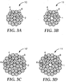
- FIGs. 3A, 3B, 3C and 3D Various stranded composite cable embodiments (10, 11, 10', 11') are illustrated by cross-sectional views in FIGs. 3A, 3B, 3C and 3D , respectively.
- the composite wires (4, 6, and 8) are stranded about a single wire (2 in FIGs. 3A and 3C ; 1 in FIGs. 3B and 3D ) defining a center longitudinal axis (not shown), in a lay direction (not shown) which is the same for each corresponding layer (12, 14 and 16 as shown in FIG. 1B ) of composite wires (4, 6, and 8).
- Such lay direction may be clockwise (right hand lay as shown in FIG. 1B ) or counter-clockwise (left hand lay, not shown).
- FIGs. 3A and 3C show a single center composite wire 2 defining a center longitudinal axis (not shown), it is additionally understood that single wire 2 may be a ductile metal wire 1, as shown in FIGs. 3B and 3D . It is further understood that each layer of composite wires exhibits a lay length (not shown in FIGs. 3A-3D ), and that the lay length of each layer of composite wires may be different, or preferably, the same lay length.
- each of the composite wires has a cross-sectional shape, in a direction substantially normal to the center longitudinal axis, generally circular, elliptical, or trapezoidal.
- each of the composite wires has a cross-sectional shape that is generally circular, and the diameter of each composite wire is at least about 0.1 mm, more preferably at least 0.5 mm; yet more preferably at least 1 mm, still more preferably at least 2 mm, most preferably at least 3 mm; and at most about 15 mm, more preferably at most 10 mm, still more preferably at most 5 mm, even more preferably at most 4 mm, most preferably at most 3 mm.
- the diameter of each composite wire may be less than 1 mm, or greater than 5 mm.
- the average diameter of the single center wire is in a range from about 0.1 mm to about 15 mm.
- the average diameter of the single center wire is desirably is at least about 0.1 mm, at least 0.5 mm, at least 1 mm, at least 2 mm, at least 3 mm, at least 4 mm, or even up to about 5 mm.
- the average diameter of the single central wire is less than about 0.5 mm, less than 1 mm, less than 3 mm, less than 5 mm, less than 10 mm, or less than 15 mm.
- the stranded composite cable may include more than three stranded layers of composite wires about the single wire defining a center longitudinal axis.
- each of the composite wires in each layer of the composite cable may be of the same construction and shape; however this is not required in order to achieve the benefits described herein.
- the present disclosure provides various embodiments of a stranded electrical power transmission cable comprising a composite core and a conductor layer around the composite core, and in which the composite core comprises any of the above-described stranded composite cables.
- the electrical power transmission cable may be useful as an overhead electrical power transmission cable, or an underground electrical power transmission cable.
- the conductor layer comprises a metal layer which contacts substantially an entire surface of the composite cable core.
- the conductor layer comprises a plurality of ductile metal conductor wires stranded about the composite cable core.
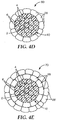
- FIGs. 4A-4E illustrate exemplary embodiments of stranded cables (30, 40, 50, 60 or 70, corresponding to FIGs. 4A, 4B, 4C , 4D and 4E ) in which one or more additional layers of ductile wires (e.g. 28, 28', 28"), for example, ductile metal conductor wires, are helically stranded around the composite cable core 10 of FIG. 3A .
- ductile wires e.g. 28, 28', 28
- ductile metal conductor wires helically stranded around the composite cable core 10 of FIG. 3A .
- the stranded cable 30 comprises a first plurality of ductile wires 28 stranded around the stranded composite cable 10 shown in FIGs. 1B , 2A-2B , and 3A .
- the stranded cable 40 comprises a second plurality of ductile wires 28' stranded around the first plurality of ductile wires 28 of stranded cable 30 of FIG. 4A .
- the stranded cable 50 comprises a third plurality of ductile wires 28" stranded around the second plurality of ductile wires 28' of stranded cable 40 of FIG. 4B .
- the respective stranded cables (30, 40 or 50) have a core comprising the stranded composite cable 10 of FIG. 3A , which includes a single wire 2 defining the center longitudinal axis 9 ( FIG. 2C ), a first layer 12 comprising a first plurality of composite wires 4 stranded around the single composite wire 2 in a first lay direction, a second layer 14 comprising a second plurality of composite wires 6 stranded around the first plurality of composite wires 4 in the first lay direction.
- the first plurality of ductile wires 28 is stranded in a lay direction opposite to that of an adjoining radial layer, for example, second layer 14 comprising the second plurality of composite wires 6.
- the first plurality of ductile wires 28 is stranded in a lay direction the same as that of an adjoining radial layer, for example, second layer 14 comprising the second plurality of composite wires 6.
- at least one of the first plurality of ductile wires 28, the second plurality of ductile wires 28', or the third plurality of ductile wires 28" is stranded in a lay direction opposite to that of an adjoining radial layer, for example, second layer 14 comprising the second plurality of composite wires 6.
- each ductile wire (28, 28', or 28”) has a cross-sectional shape, in a direction substantially normal to the center longitudinal axis, selected from circular, elliptical, or trapezoidal.
- FIGs. 4A-4C illustrate embodiments wherein each ductile wire (28, 28', or 28") has a cross-sectional shape, in a direction substantially normal to the center longitudinal axis, that is substantially circular.
- the stranded cable 60 comprises a first plurality of generally trapezoidal-shaped ductile wires 28 stranded around the stranded composite cable 10 shown in FIGs. 1B , 2A-2B .
- the stranded cable 70 further comprises a second plurality of generally trapezoidal-shaped ductile wires 28' stranded around the stranded cable 60 of FIG. 4D .
- some or all of the ductile wires may have a cross-sectional shape, in a direction substantially normal to the center longitudinal axis, that is "Z" or "S” shaped (not shown). Wires of such shapes are known in the art, and may be desirable, for example, to form an interlocking outer layer of the cable.
- the ductile wires (28, 28', or 28") comprise at least one metal selected from the group consisting of copper, aluminum, iron, zinc, cobalt, nickel, chromium, titanium, tungsten, vanadium, zirconium, manganese, silicon, alloys thereof, and combinations thereof.
- the stranded composite cables may be used as intermediate articles that are later incorporated into final articles, for example, towing cables, hoist cables, overhead electrical power transmission cables, and the like, by stranding a multiplicity of ductile wires around a core comprising composite wires, for example, the helically stranded composite cables previously described, or other stranded composite cables.
- the core can be made by stranding (e.g., helically winding) two or more layers of composite wires (4, 6, 8) around a single center wire (2) as described above using techniques known in the art.
- such helically stranded composite cable cores tend to comprise as few as 19 individual wires to 50 or more wires.
- FIGs. 5A-5C illustrate various embodiments using a maintaining means in the form of a tape 18 to hold the composite wires together after stranding.
- Figure 5A is a side view of the stranded cable 10 ( FIGs. 1B , 2A-2B , and 3A ), with an exemplary maintaining means comprising a tape 18 partially applied to the stranded composite cable 10 around the composite wires (2, 4, 6).
- tape 18 may comprise a backing 20 with an adhesive layer 22.
- the tape 18 may comprise only a backing 20, without an adhesive.
- tape 18 may be wrapped such that each successive wrap abuts the previous wrap without a gap and without overlap, as is illustrated in FIG. 5A .
- successive wraps may be spaced so as to leave a gap between each wrap or so as to overlap the previous wrap.
- the tape 18 is wrapped such that each wrap overlaps the preceding wrap by approximately 1/3 to 1/2 of the tape width.
- FIG. 5B is an end view of the stranded cable of FIG. 5A in which the maintaining means is a tape 18 comprises a backing 20 with an adhesive 22.
- suitable adhesives include, for example, (meth)acrylate (co)polymer based adhesives, poly( ⁇ -olefin) adhesives, block copolymer based adhesives, natural rubber based adhesives, silicone based adhesives, and hot melt adhesives. Pressure sensitive adhesives may be preferred in certain embodiments.
- suitable materials for tape 18 or backing 20 include metal foils, particularly aluminum; polyester; polyimide; and glass reinforced backings; provided the tape 18 is strong enough to maintain the elastic bend deformation and is capable of retaining its wrapped configuration by itself, or is sufficiently restrained if necessary.
- One particularly preferred backing 20 is aluminum.
- Such a backing preferably has a thickness of between 0.002 and 0.005 inches (0.05 to 0.13 mm), and a width selected based on the diameter of the stranded cable 10. For example, for a stranded cable 10 having two layers of stranded composite wires such as such as illustrated in Figure 5A , and having a diameter of about 0.5 inches (1.3 cm), an aluminum tape having a width of 1.0 inch (2.5 cm) is preferred.
- Some presently preferred commercially available tapes include the following Metal Foil Tapes (available from 3M Company, St. Paul, MN): Tape 438, a 0.005 inch thick (0.13 mm) aluminum backing with acrylic adhesive and a total tape thickness of 0.0072 inches (0.18 mm); Tape 431, a 0.0019 inch thick (0.05 mm) aluminum backing with acrylic adhesive and a total tape thickness of 0.0031 inches (0.08 mm); and Tape 433, a 0.002 inch thick (0.05 mm) aluminum backing with silicone adhesive and a total tape thickness of 0.0036 inches (0.09 mm).
- a suitable metal foil/glass cloth tape is Tape 363 (available from 3M Company, St. Paul, MN), as described in the Examples.
- a suitable polyester backed tape includes Polyester Tape 8402 (available from 3M Company, St. Paul, MN), with a 0.001 inch thick (0.03 mm) polyester backing, a silicone based adhesive, and a total tape thickness of 0.0018 inches (0.03 mm).
- FIG. 5C is an end view of the stranded cable of FIG. 5A in which tape 18 comprises a backing 20 without adhesive 22.
- suitable materials for backing 20 include any of those just described for use with an adhesive, with a preferred backing being an aluminum backing having a thickness of between 0.002 and 0.005 inches (0.05 to 0.13 mm) and a width of 1.0 inch (2.54 cm).
- the tape When using tape 18 as the maintaining means, either with or without adhesive 22, the tape may be applied to the stranded cable with conventional tape wrapping apparatus as is known in the art. Suitable taping machines include those available from Watson Machine, International, Patterson, NJ, such as model number CT-300 Concentric Taping Head.
- the tape overwrap station is generally located at the exit of the cable stranding apparatus and is applied to the helically stranded composite wires prior to the cable 10 being wound onto a take up spool.
- the tape 18 is selected so as to maintain the stranded arrangement of the elastically deformed composite wires.
- FIG. 5D illustrates alternative exemplary embodiments of a stranded composite cable 34 with a maintaining means in the form of a binder 24 applied to the stranded cable 10 to maintain the composite wires (2, 4, 6) in their stranded arrangement.
- Suitable binders 24 include pressure sensitive adhesive compositions comprising one or more poly (alpha-olefin) homopolymers, copolymers, terpolymers, and tetrapolymers derived from monomers containing 6 to 20 carbon atoms and photoactive crosslinking agents as described in U.S. Pat. No. 5,112,882 (Babu et al. ). Radiation curing of these materials provides adhesive films having an advantageous balance of peel and shear adhesive properties.
- the binder 24 may comprise thermoset materials, including but not limited to epoxies.
- thermoset materials including but not limited to epoxies.
- the binder 24 can be applied in the form of an adhesive supplied as a transfer tape. In this case, the binder 24 is applied to a transfer or release sheet (not shown). The release sheet is wrapped around the composite wires of the stranded cable 10. The backing is then removed, leaving the adhesive layer behind as the binder 24.
- an adhesive 22 or binder 24 may optionally be applied around each individual layer of composite wires (e.g. 12, 14, 16 in FIG. 1B ) or between any suitable layer of composite wires (e.g. 2, 4, 6, 8 in FIG. 1B ) as is desired.
- the maintaining means does not significantly add to the total diameter of the stranded composite cable 10.
- the outer diameter of the stranded composite cable including the maintaining means is no more than 110% of the outer diameter of the plurality of stranded composite wires (2, 4, 6, 8) excluding the maintaining means, more preferably no more than 105%, and most preferably no more than 102%.
- the composite wires have a significant amount of elastic bend deformation when they are stranded on conventional cabling equipment. This significant elastic bend deformation would cause the wires to return to their un-stranded or unbent shape if there were not a maintaining means for maintaining the helical arrangement of the wires. Therefore, in some embodiments, the maintaining means is selected so as to maintain significant elastic bend deformation of the plurality of stranded composite wires (e.g. 2, 4, 6, 8 in FIG. 1B ).
- the intended application for the stranded cable 10 may suggest certain maintaining means are better suited for the application.
- either the binder 24 or the tape 18 without an adhesive 22 should be selected so as to not adversely affect the transmission cable at the temperatures and other conditions experienced in this application.
- an adhesive tape 18 is used as the maintaining means, both the adhesive 22 and the backing 20 should be selected to be suitable for the intended application.
- the stranded composite wires each comprise a plurality of continuous fibers in a matrix as will be discussed in more detail later. Because the wires are composite, they do not take on a plastic deformation during the cabling operation which would be possible with ductile wires. For example, in prior art arrangements including ductile wires, the conventional cabling process could be carried out so as to permanently plastically deform the composite wires in their helical arrangement.
- the present disclosure allows use of composite wires which can provide superior desired characteristics compared to conventional non-composite wires.
- the maintaining means allows the stranded composite cable to be conveniently handled as a final article or to be conveniently handled before being incorporated into a subsequent final article.
- each of the composite wires is selected to be a fiber reinforced composite wire comprising at least one of a continuous fiber tow or a continuous monofilament fiber in a matrix.
- a preferred embodiment for the composite wires comprises a plurality of continuous fibers in a matrix.
- a preferred fiber comprises polycrystalline ⁇ -Al 2 O 3 .
- These preferred embodiments for the composite wires preferably have a tensile strain to failure of at least 0.4%, more preferably at least 0.7%. In some embodiments, at least 85% (in some embodiments, at least 90%, or even at least 95%) by number of the fibers in the metal matrix composite core are continuous.
- composite wires that could be used with the present disclosure include glass / epoxy wires; silicon carbide / aluminum composite wires; carbon / aluminum composite wires; carbon / epoxy composite wires; carbon / polyetheretherketone (PEEK) wires; carbon / (co)polymer wires; and combinations of such composite wires.
- PEEK polyetheretherketone
- suitable glass fibers include A-Glass, B-Glass, C-Glass, D-Glass, S-Glass, AR-Glass, R-Glass, fiberglass and paraglass, as known in the art.
- Other glass fibers may also be used; this list is not limited, and there are many different types of glass fibers commercially available, for example, from Corning Glass Company (Corning, NY).
- continuous glass fibers may be preferred.
- the continuous glass fibers have an average fiber diameter in a range from about 3 micrometers to about 19 micrometers.
- the glass fibers have an average tensile strength of at least 3 GPa, 4 GPa, and or even at least 5 GPa.
- the glass fibers have a modulus in a range from about 60 GPa to 95 GPa, or about 60 GPa to about 90 GPa.
- suitable ceramic fibers include metal oxide (e.g., alumina) fibers, boron nitride fibers, silicon carbide fibers, and combination of any of these fibers.
- the ceramic oxide fibers are crystalline ceramics and/or a mixture of crystalline ceramic and glass (i.e., a fiber may contain both crystalline ceramic and glass phases).
- such fibers have a length on the order of at least 50 meters, and may even have lengths on the order of kilometers or more.
- the continuous ceramic fibers have an average fiber diameter in a range from about 5 micrometers to about 50 micrometers, about 5 micrometers to about 25 micrometers about 8 micrometers to about 25 micrometers, or even about 8 micrometers to about 20 micrometers.
- the crystalline ceramic fibers have an average tensile strength of at least 1.4 GPa, at least 1.7 GPa, at least 2.1 GPa, and or even at least 2.8 GPa. In some embodiments, the crystalline ceramic fibers have a modulus greater than 70 GPa to approximately no greater than 1000 GPa, or even no greater than 420 GPa.
- suitable monofilament ceramic fibers include silicon carbide fibers.
- the silicon carbide monofilament fibers are crystalline and/or a mixture of crystalline ceramic and glass (i.e., a fiber may contain both crystalline ceramic and glass phases).
- such fibers have a length on the order of at least 50 meters, and may even have lengths on the order of kilometers or more.
- the continuous silicon carbide monofilament fibers have an average fiber diameter in a range from about 100 micrometers to about 250 micrometers.
- the crystalline ceramic fibers have an average tensile strength of at least 2.8 GPa, at least 3.5 GPa, at least 4.2 GPa and or even at least 6 GPa.
- the crystalline ceramic fibers have a modulus greater than 250 GPa to approximately no greater than 500 GPa, or even no greater than 430 GPa.
- Suitable alumina fibers are described, for example, in U.S. Pat. Nos. 4,954,462 (Wood et al. ) and 5,185,299 (Wood et al. ).
- the alumina fibers are polycrystalline alpha alumina fibers and comprise, on a theoretical oxide basis, greater than 99 percent by weight Al 2 O 3 and 0.2-0.5 percent by weight SiO 2 , based on the total weight of the alumina fibers.
- some desirable polycrystalline, alpha alumina fibers comprise alpha alumina having an average grain size of less than one micrometer (or even, in some embodiments, less than 0.5 micrometer).
- polycrystalline, alpha alumina fibers have an average tensile strength of at least 1.6 GPa (in some embodiments, at least 2.1 GPa, or even, at least 2.8 GPa).
- Exemplary alpha alumina fibers are marketed under the trade designation "NEXTEL 610" (3M Company, St. Paul, MN).
- Suitable aluminosilicate fibers are described, for example, in U.S. Pat. No. 4,047,965 (Karst et al ). Exemplary aluminosilicate fibers are marketed under the trade designations "NEXTEL 440", “NEXTEL 550", and “NEXTEL 720" by 3M Company of St. Paul, MN. Aluminoborosilicate fibers are described, for example, in U.S. Pat. No. 3,795,524 (Sowman). Exemplary aluminoborosilicate fibers are marketed under the trade designation "NEXTEL 312" by 3M Company. Boron nitride fibers can be made, for example, as described in U.S.
- Exemplary silicon carbide fibers are marketed, for example, by COI Ceramics of San Diego, CA under the trade designation "NICALON” in tows of 500 fibers, from Ube Industries of Japan, under the trade designation "TYRANNO”, and from Dow Corning of Midland, MI under the trade designation "SYLRAMIC".
- Suitable carbon fibers include commercially available carbon fibers such as the fibers designated as PANEX® and PYRON® (available from ZOLTEK, Bridgeton, MO), THORNEL (available from CYTEC Industries, Inc., West Paterson, NJ), HEXTOW (available from HEXCEL, Inc., Southbury, CT), and TORAYCA (available from TORAY Industries, Ltd. Tokyo, Japan).
- Such carbon fibers may be derived from a polyacrylonitrile (PAN) precursor.
- PAN polyacrylonitrile
- Other suitable carbon fibers include PAN-IM, PAN-HM, PAN UHM, PITCH or rayon byproducts, as known in the art.
- Additional suitable commercially available fibers include ALTEX (available from Sumitomo Chemical Company, Osaka, Japan), and ALCEN (available from Nitivy Company, Ltd., Tokyo, Japan).
- Suitable fibers also include shape memory alloy (i.e., a metal alloy that undergoes a Martensitic transformation such that the metal alloy is deformable by a twinning mechanism below the transformation temperature, wherein such deformation is reversible when the twin structure reverts to the original phase upon heating above the transformation temperature).
- shape memory alloy i.e., a metal alloy that undergoes a Martensitic transformation such that the metal alloy is deformable by a twinning mechanism below the transformation temperature, wherein such deformation is reversible when the twin structure reverts to the original phase upon heating above the transformation temperature.
- shape memory alloy fibers are available, for example, from Johnson Matthey Company (West Whiteland, PA).
- the ceramic fibers are in tows.
- Tows are known in the fiber art and refer to a plurality of (individual) fibers (typically at least 100 fibers, more typically at least 400 fibers) collected in a roving-like form.
- tows comprise at least 780 individual fibers per tow, in some cases at least 2600 individual fibers per tow, and in other cases at least 5200 individual fibers per tow.
- Tows of ceramic fibers are generally available in a variety of lengths, including 300 meters, 500 meters, 750 meters, 1000 meters, 1500 meters, 2500 meters, 5000 meters, 7500 meters, and longer.
- the fibers may have a cross-sectional shape that is circular or elliptical.
- Fibers may typically include an organic sizing material added to the fiber during manufacture to provide lubricity and to protect the fiber strands during handling.
- the sizing may be removed, for example, by dissolving or burning the sizing away from the fibers.
- the fibers may also have coatings used, for example, to enhance the wettability of the fibers, to reduce or prevent reaction between the fibers and molten metal matrix material. Such coatings and techniques for providing such coatings are known in the fiber and composite art.
- each of the composite wires is selected from a metal matrix composite wire and a polymer composite wire.
- Suitable composite wires are disclosed, for example, in U.S. Pat. Nos. 6,180,232 ; 6,245,425 ; 6,329,056 ; 6,336,495 ; 6,344,270 ; 6,447,927 ; 6,460,597 ; 6,544,645 ; 6,559,385 , 6,723,451 ; and 7,093,416 .
- the ceramic fiber reinforced aluminum matrix composite wires preferably comprise continuous fibers of polycrystalline ⁇ -Al 2 O 3 encapsulated within a matrix of either substantially pure elemental aluminum or an alloy of pure aluminum with up to about 2% by weight copper, based on the total weight of the matrix.
- the preferred fibers comprise equiaxed grains of less than about 100 nm in size, and a fiber diameter in the range of about 1-50 micrometers. A fiber diameter in the range of about 5-25 micrometers is preferred with a range of about 5-15 micrometers being most preferred.
- Preferred fiber reinforced composite wires to the present disclosure have a fiber density of between about 3.90-3.95 grams per cubic centimeter.
- preferred fibers are those described in U.S. Pat. No. 4,954,462 (Wood et al. ).
- Preferred fibers are available commercially under the trade designation "NEXTEL 610" alpha alumina based fibers (available from 3M Company, St. Paul, MN).
- the encapsulating matrix is selected to be such that it does not significantly react chemically with the fiber material (i.e., is relatively chemically inert with respect the fiber material, thereby eliminating the need to provide a protective coating on the fiber exterior.
- substantially pure elemental aluminum In certain presently preferred embodiments of a composite wire, the use of a matrix comprising either substantially pure elemental aluminum, or an alloy of elemental aluminum with up to about 2% by weight copper, based on the total weight of the matrix, has been shown to produce successful wires.
- substantially pure elemental aluminum As used herein the terms “substantially pure elemental aluminum”, “pure aluminum” and “elemental aluminum” are interchangeable and are intended to mean aluminum containing less than about 0.05% by weight impurities.
- the composite wires comprise between about 30-70% by volume polycrystalline ⁇ -Al 2 O 3 fibers, based on the total volume of the composite wire, within a substantially elemental aluminum matrix. It is presently preferred that the matrix contains less than about 0.03% by weight iron, and most preferably less than about 0.01% by weight iron, based on the total weight of the matrix. A fiber content of between about 40-60% polycrystalline ⁇ -Al 2 O 3 fibers is preferred.
- Such composite wires, formed with a matrix having a yield strength of less than about 20 MPa and fibers having a longitudinal tensile strength of at least about 2.8 GPa have been found to have excellent strength characteristics.
- the matrix may also be formed from an alloy of elemental aluminum with up to about 2% by weight copper, based on the total weight of the matrix.
- composite wires having an aluminum/copper alloy matrix preferably comprise between about 30-70% by volume polycrystalline ⁇ -Al 2 O 3 fibers, and more preferably therefore about 40-60% by volume polycrystalline ⁇ -Al 2 O 3 fibers, based on the total volume of the composite.
- the matrix preferably contains less than about 0.03% by weight iron, and most preferably less than about 0.01% by weight iron based on the total weight of the matrix.
- the aluminum/copper matrix preferably has a yield strength of less than about 90 MPa, and, as above, the polycrystalline ⁇ -Al 2 O 3 fibers have a longitudinal tensile strength of at least about 2.8 GPa.
- Composite wires preferably are formed from substantially continuous polycrystalline ⁇ -Al 2 O 3 fibers contained within the substantially pure elemental aluminum matrix or the matrix formed from the alloy of elemental aluminum and up to about 2% by weight copper described above.
- Such wires are made generally by a process in which a spool of substantially continuous polycrystalline ⁇ -Al 2 O 3 fibers, arranged in a fiber tow, is pulled through a bath of molten matrix material. The resulting segment is then solidified, thereby providing fibers encapsulated within the matrix.
- Exemplary metal matrix materials include aluminum, e.g., high purity, (e.g., greater than 99.95%) elemental aluminum, zinc, tin, magnesium, and alloys thereof (e.g., an alloy of aluminum and copper).
- the matrix material is selected such that the matrix material does not significantly chemically react with the fiber (i.e., is relatively chemically inert with respect to fiber material), for example, to eliminate the need to provide a protective coating on the fiber exterior.
- the matrix material desirably includes aluminum and alloys thereof.
- the metal matrix comprises at least 98 percent by weight aluminum, at least 99 percent by weight aluminum, greater than 99.9 percent by weight aluminum, or even greater than 99.95 percent by weight aluminum.
- Exemplary aluminum alloys of aluminum and copper comprise at least 98 percent by weight A1 and up to 2 percent by weight Cu.
- useful alloys are 1000, 2000, 3000, 4000, 5000, 6000, 7000 and/or 8000 series aluminum alloys (Aluminum Association designations). Although higher purity metals tend to be desirable for making higher tensile strength wires, less pure forms of metals are also useful.
- Suitable metals are commercially available.
- aluminum is available under the trade designation "SUPER PURE ALUMINUM; 99.99% Al” from Alcoa of Pittsburgh, PA.
- Aluminum alloys e.g., A1-2% by weight Cu (0.03% by weight impurities)
- Zinc and tin are available, for example, from Metal Services, St. Paul, MN ("pure zinc”; 99.999% purity and "pure tin”; 99.95% purity).
- magnesium is available under the trade designation "PURE” from Magnesium Elektron, Manchester, England.
- Magnesium alloys e.g., WE43A, EZ33A, AZ81A, and ZE41A
- TIMET Denver, CO.
- the metal matrix composite wires typically comprise at least 15 percent by volume (in some embodiments, at least 20, 25, 30, 35, 40, 45, or even 50 percent by volume) of the fibers, based on the total combined volume of the fibers and matrix material. More typically the composite cores and wires comprise in the range from 40 to 75 (in some embodiments, 45 to 70) percent by volume of the fibers, based on the total combined volume of the fibers and matrix material.
- Metal matrix composite wires can be made using techniques known in the art. Continuous metal matrix composite wire can be made, for example, by continuous metal matrix infiltration processes. One suitable process is described, for example, in U.S. Pat. No. 6,485,796 (Carpenter et al. ). Wires comprising polymers and fiber may be made by pultrusion processes which are known in the art.
- the composite wires are selected to include polymer composite wires.
- the polymer composite wires comprise at least one continuous fiber in a polymer matrix.
- the at least one continuous fiber comprises metal, carbon, ceramic, glass, and combinations thereof.
- the at least one continuous fiber comprises titanium, tungsten, boron, shape memory alloy, carbon nanotubes, graphite, silicon carbide, boron, aramid, poly(p-phenylene-2,6-benzobisoxazole)3, and combinations thereof.
- the polymer matrix comprises a (co)polymer selected from an epoxy, an ester, a vinyl ester, a polyimide, a polyester, a cyanate ester, a phenolic resin, a bis-maleimide resin, and combinations thereof.
- Ductile metal wires for stranding around a composite core to provide a composite cable are known in the art.
- Preferred ductile metals include iron, steel, zirconium, copper, tin, cadmium, aluminum, manganese, and zinc; their alloys with other metals and/or silicon; and the like.
- Copper wires are commercially available, for example from Southwire Company, Carrolton, GA.
- Aluminum wires are commercially available, for example from Nexans, Weyburn, Canada or Southwire Company, Carrolton, GA under the trade designations "1350-H19 ALUMINUM" and "1350-H0 ALUMINUM".
- copper wires have a thermal expansion coefficient in a range from about 12 ppm/°C to about 18 ppm/°C over at least a temperature range from about 20°C to about 800°C.
- copper alloy wires have a thermal expansion coefficient in a range from about 10 ppm/°C to about 25 ppm/°C over at least a temperature range from about 20°C to about 800°C.
- the wires may be in any of a variety shapes (e.g., circular, elliptical, and trapezoidal).
- aluminum wire have a thermal expansion coefficient in a range from about 20 ppm/°C to about 25 ppm/°C over at least a temperature range from about 20°C to about 500°C.
- aluminum wires e.g., "1350-H19 ALUMINUM"
- aluminum wires e.g., "1350-H0 ALUMINUM" have a tensile breaking strength greater than 41 MPa (6 ksi) to no greater than 97 MPa (14 ksi), or even no greater than 83 MPa (12 ksi).
- Aluminum alloy wires are commercially available, for example, aluminum-zirconium alloy wires sold under the trade designations "ZTAL,” “XTAL,” and “KTAL” (available from Sumitomo Electric Industries, Osaka, Japan), or "6201” (available from Southwire Company, Carrolton, GA).
- aluminum alloy wires have a thermal expansion coefficient in a range from about 20 ppm/°C to about 25 ppm/°C over at least a temperature range from about 20°C to about 500°C.
- the present disclosure is preferably carried out so as to provide very long stranded cables. It is also preferable that the composite wires within the stranded cable 10 themselves are continuous throughout the length of the stranded cable. In one preferred embodiment, the composite wires are substantially continuous and at least 150 meters long. More preferably, the composite wires are continuous and at least 250 meters long, more preferably at least 500 meters, still more preferably at least 750 meters, and most preferably at least 1000 meters long in the stranded cable 10.
- the disclosure provides a method of making the stranded composite cables described above, the method comprising stranding a first plurality of composite wires about a single wire defining a center longitudinal axis, wherein stranding the first plurality of composite wires is carried out in a first lay direction at a first lay angle defined relative to the center longitudinal axis, and wherein the first plurality of composite wires has a first lay length; and stranding a second plurality of composite wires around the first plurality of composite wires, wherein stranding the second plurality of composite wires is carried out in the first lay direction at a second lay angle defined relative to the center longitudinal axis, and wherein the second plurality of composite wires has a second lay length, further wherein a relative difference between the first lay angle and the second lay angle is no greater than 4°.
- the method further comprises stranding a plurality of ductile wires around the composite wires.
- the composite wires may be stranded or helically wound as is known in the art on any suitable cable stranding equipment, such as planetary cable stranders available from Cortinovis, Spa, of Bergamo, Italy, and from Watson Machinery International, of Patterson, NJ. In some embodiments, it may be advantageous to employ a rigid strander as is known in the art.
- any suitably-sized composite wire can be used, it is preferred for many embodiments and many applications that the composite wires have a diameter from 1 mm to 4 mm, however larger or smaller composite wires can be used.
- the stranded composite cable includes a plurality of stranded composite wires that are helically stranded in a lay direction to have a lay factor of from 10 to 150.
- the "lay factor" of a stranded cable is determined by dividing the length of the stranded cable in which a single wire 12 completes one helical revolution by the nominal outside of diameter of the layer that includes that strand.
- the center wire, or the intermediate unfinished stranded composite cable which will have one or more additional layers wound about it is pulled through the center of the various carriages, with each carriage adding one layer to the stranded cable.
- the individual wires to be added as one layer are simultaneously pulled from their respective bobbins while being rotated about the center axis of the cable by the motor driven carriage. This is done in sequence for each desired layer.
- the result is a helically stranded core.
- a maintaining means such as tape, for example, can be applied to the resulting stranded composite core to aid in holding the stranded wires together.
- stranded composite cables according to the present disclosure can be made by stranding composite wires around a single wire in the same lay direction, as described above.
- the single wire may comprise a composite wire or a ductile wire.
- At least two layers of composite wires are formed by stranding composite wires about the single wire core, for example, 19 or 37 wires formed in at least two layers around a single center wire, as shown in FIG. 1B .
- a spool of wire 81 is provided at the head of conventional planetary stranding machine 80, wherein spool 81 is free to rotate, with tension capable of being applied via a braking system where tension can be applied to the core during payoff (in some embodiments, in the range of 0-91 kg (0-200 lbs.)).
- Single wire 90 is threaded through bobbin carriages 82, 83, through the closing dies 84, 85, around capstan wheels 86 and attached to take-up spool 87.
- individual composite wires are provided on separate bobbins 88 which are placed in a number of motor driven carriages 82, 83of the stranding equipment.
- the range of tension required to pull wire 89A, 89B from the bobbins 88 is typically 4.5-22.7 kg (10-50 lbs.).
- Wires 89 A, 89B of each layer are brought together at the exit of each carriage at a closing die 84, 85 and arranged over the center wire or over the preceding layer.
- Layers of composite wires comprising the composite cable are helically stranded in the same direction as previously described.
- the center wire, or the intermediate unfinished stranded composite cable which may have one or more additional layers wound about it, is pulled through the center of the various carriages, with each carriage adding one layer to the stranded cable.
- the individual wires to be added as one layer are simultaneously pulled from their respective bobbins while being rotated about the center axis of the cable by the motor driven carriage. This is done in sequence for each desired layer. The result is a helically stranded composite cable 91 that can be cut and handled conveniently without loss of shape or unraveling.
- stranded composite cables comprise stranded composite wires having a length of at least 100 meters, at least 200 meters, at least 300 meters, at least 400 meters, at least 500 meters, at least 1000 meters, at least 2000 meters, at least 3000 meters, or even at least 4500 meters or more.
- the cable maintains its helically stranded arrangement because during manufacture, the metallic wires are subjected to stresses, including bending stresses, beyond the yield stress of the wire material but below the ultimate or failure stress. This stress is imparted as the wire is helically wound about the relatively small radius of the preceding layer or center wire. Additional stresses are imparted at closing dies 84, 85 which apply radial and shear forces to the cable during manufacture. The wires therefore plastically deform and maintain their helically stranded shape.
- closing dies 84, 85 are typically sized to minimize the deformation stresses on the wires of the layer being wound.
- the internal diameter of the closing die is tailored to the size of the external layer diameter.
- the closing die is sized such that it is in the range from 0-2.0% larger, relative to the external diameter of the cable. (i.e., the interior die diameters are in a range of 1.00 to 1.02 times the exterior cable diameter).
- Exemplary closing dies are cylinders, and are held in position, for example, using bolts or other suitable attachments.
- the dies can be made, for example, of hardened tool steel.
- the resulting finished stranded composite cable may pass through other stranding stations, if desired, and ultimately wound onto take-up spool 87 of sufficient diameter to avoid cable damage.
- techniques known in the art for straightening the cable may be desirable.
- the finished cable can be passed through a straightener device comprised of rollers (each roller being for example, 10-15 cm (4-6 inches), linearly arranged in two banks, with, for example, 5-9 rollers in each bank. The distance between the two banks of rollers may be varied so that the rollers just impinge on the cable or cause severe flexing of the cable.
- the two banks of rollers are positioned on opposing sides of the cable, with the rollers in one bank matching up with the spaces created by the opposing rollers in the other bank. Thus, the two banks can be offset from each other. As the cable passes through the straightening device, the cable flexes back and forth over the rollers, allowing the strands in the conductor to stretch to the same length, thereby reducing or eliminating slack strands.
- the single center wire at an elevated temperature (e.g., at least 25°C, 50°C, 75°C, 100°C, 125°C, 150°C, 200°C, 250°C, 300°C, 400°C, or even, in some embodiments, at least 500°C) above ambient temperature (e.g., 22°C).
- the single center wire can be brought to the desired temperature, for example, by heating spooled wire (e.g., in an oven for several hours).
- the heated spooled wire is placed on the pay-off spool (see, e.g., pay-off spool 81 in FIG. 6 ) of a stranding machine.
- the spool at elevated temperature is in the stranding process while the wire is still at or near the desired temperature (typically within about 2 hours).
- the composite wires on the payoff spools that form the outer layers of the cable may be at the ambient temperature. That is, in some embodiments, it may be desirable to have a temperature differential between the single wire and the composite wires which form the outer composite layers during the stranding process. In some embodiments, it may be desirable to conduct the stranding with a single wire tension of at least 100 kg, 200 kg, 500 kg, 1000 kg., or even at least 5000 kg.
- Stranded cables of the present disclosure are useful in numerous applications. Such stranded cables are believed to be particularly desirable for use in electrical power transmission cables, which may include overhead and underground electrical power transmission cables, due to their combination of low weight, high strength, good electrical conductivity, low coefficient of thermal expansion, high use temperatures, and resistance to corrosion.
- FIG. 7 is a cross-sectional end view of a helically stranded composite cable 80 including one or more layers comprising a plurality of ductile wires (28, 28') stranded around a core 32' ( FIG. 5C ) comprising helically stranded composite wires (2, 4, 6, 8) stranded in the same lay direction and held in place by a maintaining means such as tape 18 wrapped around at least the second layer of stranded composite wires 16 according to another exemplary embodiment of the present disclosure.
- the ductile wires (28, 28') act as electrical conductors, i.e. ductile wire conductors.
- the electrical power transmission cable may include two layers of ductile conductor wires (28, 28'). More layers of conductor wires (not shown in FIG. 7 ) may be used as desired.
- each conductor layer comprises a plurality of conductor wires (28, 28') as is known in the art.
- Suitable materials for the ductile conductor wires (28, 28') includes aluminum and aluminum alloys.
- the ductile conductor wires (28, 28') may be stranded about the stranded composite core (e.g. 32') by suitable cable stranding equipment as is known in the art (see, e.g. FIG. 6 ).
- the weight percentage of composite wires within the electrical power transmission cable will depend upon the design of the transmission line.
- the aluminum or aluminum alloy conductor wires may be any of the various materials known in the art of overhead power transmission, including, but not limited to, 1350 Al (ASTM B609-91), 1350-H19 Al (ASTM B230-89), or 6201 T-81 Al (ASTM B399-92).
- a preferred embodiment of the electrical power transmission cable is an overhead electrical power transmission cable.
- the materials for the maintaining means should be selected for use at temperatures of at least 100°C, or 240°C, or 300°C, depending on the application.
- the maintaining means should not corrode the aluminum conductor layer, or give off undesirable gasses, or otherwise impair the transmission cable at the anticipated temperatures during use.
- the stranded cable in which the stranded cable is to be used as a final article itself, or in which it is to be used as an intermediary article or component in a different subsequent article, it is preferred that the stranded cable be free of electrical power conductor layers around the plurality of composite wires.
- the starting material consisted of 12 foot (3.7 m) lengths cut from a reel of normal production 3M ACCR aluminum-matrix composite (AMC) cable (type 795-T16, available from 3M Company, St. Paul, MN).
- AMC aluminum-matrix composite
- This construction comprises a core containing 19 AMC wires (produced by 3M Company, St. Paul, MN) having a diameter of 0.084 inch (2.13 mm), surrounded by 26 Al-Zr (aluminum-zirconium) metal wires drawn from Al-Zr rod (produced by Lamifil, Inc., Hemiksem, Belguim) and having a diameter of 0.175 inch (4.45 mm).
- the basic construction of this cable is shown in FIG. 4B .
- the starting 12 foot (3.7 m) length of normal-production cable was first disassembled into its constituent wires, taking care to avoid altering the existing helical shape of the Al-Zr wires.
- the two helical layers of the core were constructed to the desired lay length and orientation using a simple tabletop fixture.
- the wires were first secured at one end to a hand-cranked cap and then threaded though a "rosette"-shaped guide plate to spread the individual composite wires into an arrangement suitable for stranding.
- the crank was simultaneously turned by one operator, while another operator moved the wire guide along the table following marked quarter-lay-length intervals.
- the six stranding conditions may be viewed as a roughly-orthogonal design on inner-core lay angle and relative outer-core lay length, as described below.
- both of these variables influence the crossing angle (i.e., the relative difference between the lay angles of the adjacent inner and outer layers of helically stranded wire) between inner and outer core wires, which may be important to the mechanism resulting in improved composite cable tensile strength.
- the inner Al-Zr conductor wire layer has a left-hand lay direction at a target lay length of 10.0 inch (25.4 cm), and the outer Al-Zr conductor wire layer has a right-hand lay direction at a target lay length of 13.0 inch (33.0 cm). Measured average values for these layers differ from target by 0.65 inch (1.6 cm) or less, well within the desired stranding specifications. Final diameters of the conductor cable samples ranged from 1.122 inch to 1.136 inch (28.50 to 28.85 mm), not far from the original diameter of 1.124 inch (28.55 mm).
- any curvature within about 2 feet (0.6 m) of one end of the cable sample was removed by careful "back-bending" of the cable at close intervals.
- a hose clamp was then applied to prevent any disturbance of the wires within the inner test span.
- a thick layer of duct tape was then wrapped adjacent to this clamp, to serve as both a seal and a centering device in the resin-casting die.
- the ends of the Al-Zr wires were then carefully spread out ("broomed") into a conical shape at a maximum angle of about 30°, and the exposed core tape was removed to allow the core wires to spread out naturally. If there were any oily residues on the wires from earlier operations, the wires were cleaned using acetone, 2-butanone, or a similar solvent, followed by thorough drying. If the wires were already clean, this step was not necessary.
- the prepared cable end was then positioned inside a split-shell socket.
- this socket has a tapered bore, as well as holes designed for later securing it into a tensile testing machine.
- the two shell halves were then clamped together, capturing about 1 inch (2.5 cm) of the tape wrap to form a leak-free seal.
- the Al-Zr wires were then trimmed off at a level just above the end of the socket, but the full lengths of the core wires were left intact.
- the socket was then mounted vertically, with the cable sample hanging from the bottom.
- a freshly-prepared batch of two-part "Wirelock" Socket Compound (Millfield Enterprises Ltd., Newburn, Newcastle-upon-Tyne, England) was then poured into the socket to completely fill it. Once the compound had gelled (about 15 minutes), a cardboard extension tube was added around the exposed core wires. Then, more Wirelock compound was prepared, and the extension tube was also filled. After allowing the assembly to cure undisturbed for a minimum of 45 minutes, all steps were then repeated for the other end of the cable sample. Another 12 hours was allowed to obtain full resin curing prior to the tensile test.
- the finished test sample was then mounted into the tensile testing machine.
- This machine is capable of reaching the expected breaking load of the sample at a controlled rate, using either a specified crosshead speed or a specified force rate, and had a properly-calibrated load cell. Care was taken to ensure that the sample was mounted with the two sockets closely aligned along the machine axis to minimize bending loads.
- the hose clamps were removed from the sample and a mild pre-tension was applied, typically 500-1000 lbs (4.5-9.0 kN). Sample alignment was verified, and the cable ends were wiggled to help release any friction or binding.
- FIG. 8 shows a plot of the effect of the relative difference in lay angle between inner and outer wire layers (Inner-Core Lay Angle), on measured tensile strength for exemplary helically stranded composite cables of the present disclosure.
- FIG. 8 shows the response of tensile strength to changes in the inner-core lay angle. The trend is statistically highly significant, and is described by a quadratic fit with an adjusted coefficient of determination (R 2 ) of 0.994.
- FIG. 9 shows a plot of the effect of relative difference in lay length between outer and inner wire layers (Relative Outer-Core Lay Length) on the measured tensile strength for exemplary helically stranded composite cables of the present disclosure. Again, the trend is statistically highly significant, and is described by a quadratic fit with an adjusted coefficient of determination (R 2 ) of 0.975.
- FIG. 10 shows a plot of the relative difference between lay angles of the inner and outer layers (Outer/Inner Lay Crossing Angle) on measured tensile strength for exemplary helically stranded composite cables of the present disclosure. This trend is statistically highly significant, and is described by a quadratic fit with an adjusted coefficient of determination (R 2 ) of 0.904.
- the tensile strength of an ACCR composite cable with a 19-wire core can be substantially increased by altering the core construction so as to minimize the crossing angle between inner and outer core wires.
- Overall longer core lay lengths provide some benefit, primarily due to the associated crossing-angle decrease.
- the simplest and most effective method of obtaining increased tensile strength is to reverse the lay orientation of alternate core layers so that all core layers have the same orientation.
Applications Claiming Priority (2)
| Application Number | Priority Date | Filing Date | Title |
|---|---|---|---|
| US12/192,436 US8525033B2 (en) | 2008-08-15 | 2008-08-15 | Stranded composite cable and method of making and using |
| PCT/US2009/050448 WO2010019333A1 (en) | 2008-08-15 | 2009-07-14 | Stranded composite cable and method of making and using |
Publications (2)
| Publication Number | Publication Date |
|---|---|
| EP2321830A1 EP2321830A1 (en) | 2011-05-18 |
| EP2321830B1 true EP2321830B1 (en) | 2016-04-06 |
Family
ID=41059752
Family Applications (1)
| Application Number | Title | Priority Date | Filing Date |
|---|---|---|---|
| EP09790358.7A Active EP2321830B1 (en) | 2008-08-15 | 2009-07-14 | Stranded composite cable and method of making and using |
Country Status (11)
| Country | Link |
|---|---|
| US (1) | US8525033B2 (pl) |
| EP (1) | EP2321830B1 (pl) |
| JP (1) | JP5628172B2 (pl) |
| KR (1) | KR101620124B1 (pl) |
| CN (2) | CN102124528A (pl) |
| BR (1) | BRPI0912464B1 (pl) |
| CA (1) | CA2733530C (pl) |
| ES (1) | ES2580758T3 (pl) |
| PL (1) | PL2321830T3 (pl) |
| RU (1) | RU2447526C1 (pl) |
| WO (1) | WO2010019333A1 (pl) |
Cited By (1)
| Publication number | Priority date | Publication date | Assignee | Title |
|---|---|---|---|---|
| DE102018208414A1 (de) * | 2018-05-28 | 2019-11-28 | Thyssenkrupp Ag | Verfahren zur Herstellung von Formlitze, Verfahren zur Herstellung eines Elektromotors, sowie Verwendung von Formlitze |
Families Citing this family (167)
| Publication number | Priority date | Publication date | Assignee | Title |
|---|---|---|---|---|
| US8413723B2 (en) | 2006-01-12 | 2013-04-09 | Schlumberger Technology Corporation | Methods of using enhanced wellbore electrical cables |
| US7635023B2 (en) | 2006-04-21 | 2009-12-22 | Shell Oil Company | Time sequenced heating of multiple layers in a hydrocarbon containing formation |
| CA2692403C (en) | 2007-07-30 | 2016-08-30 | Southwire Company | Vibration resistant cable |
| US20090200290A1 (en) | 2007-10-19 | 2009-08-13 | Paul Gregory Cardinal | Variable voltage load tap changing transformer |
| US8525033B2 (en) | 2008-08-15 | 2013-09-03 | 3M Innovative Properties Company | Stranded composite cable and method of making and using |
| US20100059249A1 (en) * | 2008-09-09 | 2010-03-11 | Powers Wilber F | Enhanced Strength Conductor |
| FR2941812A1 (fr) * | 2009-02-03 | 2010-08-06 | Nexans | Cable de transmission electrique a haute tension. |
| US20100212932A1 (en) * | 2009-02-24 | 2010-08-26 | Southwire Company | Electrical Cable |
| US8434555B2 (en) | 2009-04-10 | 2013-05-07 | Shell Oil Company | Irregular pattern treatment of a subsurface formation |
| US9412492B2 (en) * | 2009-04-17 | 2016-08-09 | Schlumberger Technology Corporation | Torque-balanced, gas-sealed wireline cables |
| US11387014B2 (en) | 2009-04-17 | 2022-07-12 | Schlumberger Technology Corporation | Torque-balanced, gas-sealed wireline cables |
| US9590408B2 (en) * | 2009-04-27 | 2017-03-07 | Fredrik Dahl | Device for grounding |
| KR101709368B1 (ko) | 2009-07-16 | 2017-02-22 | 쓰리엠 이노베이티브 프로퍼티즈 컴파니 | 수중 복합 케이블 및 방법 |
| CN101996706B (zh) * | 2009-08-25 | 2015-08-26 | 清华大学 | 一种耳机线及具有该耳机线的耳机 |
| CN101998200A (zh) * | 2009-08-25 | 2011-03-30 | 鸿富锦精密工业(深圳)有限公司 | 一种耳机线及具有该耳机线的耳机 |
| CA2774775A1 (en) | 2009-09-22 | 2011-03-31 | Schlumberger Canada Limited | Wireline cable for use with downhole tractor assemblies |
| US8257112B2 (en) | 2009-10-09 | 2012-09-04 | Shell Oil Company | Press-fit coupling joint for joining insulated conductors |
| US9466896B2 (en) | 2009-10-09 | 2016-10-11 | Shell Oil Company | Parallelogram coupling joint for coupling insulated conductors |
| MX348463B (es) | 2009-11-11 | 2017-06-14 | Borealis Ag | Composicion polimerica reticutable y cable con propiedades electricas ventajosas. |
| AU2010318181B2 (en) | 2009-11-11 | 2014-03-27 | Borealis Ag | A polymer composition and a power cable comprising the polymer composition |
| WO2011057926A1 (en) | 2009-11-11 | 2011-05-19 | Borealis Ag | A polymer composition comprising a polyolefin produced in a high pressure process, a high pressure process and an article |
| AU2010318178B2 (en) | 2009-11-11 | 2013-10-24 | Borealis Ag | A cable and production process thereof |
| US20120298403A1 (en) * | 2010-02-01 | 2012-11-29 | Johnson Douglas E | Stranded thermoplastic polymer composite cable, method of making and using same |
| JP5722920B2 (ja) | 2010-02-18 | 2015-05-27 | スリーエム イノベイティブ プロパティズ カンパニー | 複合体ケーブルのための圧縮コネクタ及びアセンブリ並びにそれらを作製及び使用するための方法 |
| JP2013524465A (ja) * | 2010-04-09 | 2013-06-17 | シエル・インターナシヨナル・リサーチ・マートスハツペイ・ベー・ヴエー | 絶縁ブロックおよび絶縁導体ヒータへの設置方法 |
| US8939207B2 (en) | 2010-04-09 | 2015-01-27 | Shell Oil Company | Insulated conductor heaters with semiconductor layers |
| US8485256B2 (en) | 2010-04-09 | 2013-07-16 | Shell Oil Company | Variable thickness insulated conductors |
| US9145627B2 (en) * | 2010-09-17 | 2015-09-29 | 3M Innovative Properties Company | Fiber-reinforced nanoparticle-loaded thermoset polymer composite wires and cables, and methods |
| US8586866B2 (en) | 2010-10-08 | 2013-11-19 | Shell Oil Company | Hydroformed splice for insulated conductors |
| US8943686B2 (en) | 2010-10-08 | 2015-02-03 | Shell Oil Company | Compaction of electrical insulation for joining insulated conductors |
| US8857051B2 (en) | 2010-10-08 | 2014-10-14 | Shell Oil Company | System and method for coupling lead-in conductor to insulated conductor |
| GB201017181D0 (en) * | 2010-10-12 | 2010-11-24 | Artificial Lift Co Ltd | Permanent magnet motor and pump on umbilical |
| EP3591670A1 (en) | 2010-11-03 | 2020-01-08 | Borealis AG | A polymer composition and a power cable comprising the polymer composition |
| US20120170900A1 (en) * | 2011-01-05 | 2012-07-05 | Alcan Products Corporation | Aluminum Alloy Conductor Composite Reinforced for High Voltage Overhead Power Lines |
| WO2012111832A1 (ja) * | 2011-02-17 | 2012-08-23 | 矢崎総業株式会社 | シールドスリーブ |
| WO2012136418A1 (en) * | 2011-04-04 | 2012-10-11 | Nv Bekaert Sa | Heating cable comprising steel monofilaments |
| EP2695247A4 (en) | 2011-04-08 | 2015-09-16 | Shell Int Research | SYSTEMS FOR CONNECTING INSULATED LADDER |
| BR112013025217B8 (pt) | 2011-04-12 | 2021-03-23 | Ticona Llc | haste compósita e método para a formação de uma haste compósita |
| US9190184B2 (en) | 2011-04-12 | 2015-11-17 | Ticona Llc | Composite core for electrical transmission cables |
| CN108407338B (zh) | 2011-04-12 | 2021-05-11 | 提克纳有限责任公司 | 用于浸渍纤维粗纱的模具和方法 |
| ES2617596T3 (es) | 2011-04-12 | 2017-06-19 | Southwire Company, Llc | Cables de transmisión eléctrica con núcleos de material compuesto |
| CN103547440B (zh) | 2011-04-12 | 2017-03-29 | 提克纳有限责任公司 | 用于浸渍纤维粗纱的模具浸渍部分和方法 |
| JP2014515868A (ja) | 2011-04-12 | 2014-07-03 | ティコナ・エルエルシー | 海底アプリケーションに使用するための海底ケーブル |
| CA2775445C (en) | 2011-04-29 | 2019-04-09 | Ticona Llc | Die and method for impregnating fiber rovings |
| EP2701886B1 (en) | 2011-04-29 | 2016-11-30 | Ticona LLC | Die with flow diffusing gate passage and method for impregnating fiber rovings |
| CA2775442C (en) | 2011-04-29 | 2019-01-08 | Ticona Llc | Impregnation section with upstream surface and method for impregnating fiber rovings |
| US8658897B2 (en) * | 2011-07-11 | 2014-02-25 | Tangitek, Llc | Energy efficient noise dampening cables |
| US10336016B2 (en) | 2011-07-22 | 2019-07-02 | Ticona Llc | Extruder and method for producing high fiber density resin structures |
| CN104011327B (zh) | 2011-10-07 | 2016-12-14 | 国际壳牌研究有限公司 | 利用地下地层中的绝缘导线的介电性能来确定绝缘导线的性能 |
| JO3139B1 (ar) | 2011-10-07 | 2017-09-20 | Shell Int Research | تشكيل موصلات معزولة باستخدام خطوة اختزال أخيرة بعد المعالجة الحرارية. |
| JO3141B1 (ar) | 2011-10-07 | 2017-09-20 | Shell Int Research | الوصلات المتكاملة للموصلات المعزولة |
| US9125301B2 (en) * | 2011-10-18 | 2015-09-01 | Integrated Microwave Corporation | Integral heater assembly and method for carrier or host board of electronic package assembly |
| US9321073B2 (en) | 2011-12-09 | 2016-04-26 | Ticona Llc | Impregnation section of die for impregnating fiber rovings |
| US9283708B2 (en) | 2011-12-09 | 2016-03-15 | Ticona Llc | Impregnation section for impregnating fiber rovings |
| WO2013086269A1 (en) | 2011-12-09 | 2013-06-13 | Ticona Llc | Impregnation section of die for impregnating fiber rovings |
| US9409355B2 (en) | 2011-12-09 | 2016-08-09 | Ticona Llc | System and method for impregnating fiber rovings |
| BR112014012309A2 (pt) | 2011-12-09 | 2017-06-13 | Ticona Llc | fita de polímero reforçado com fibra assimétrica |
| US9909419B2 (en) * | 2012-03-09 | 2018-03-06 | Nv Bekaert Sa | Strand, cable bolt and its installation |
| CA2865362C (en) | 2012-04-24 | 2020-07-14 | Nv Bekaert Sa | Multi-strand hybrid rope |
| US9410644B2 (en) | 2012-06-15 | 2016-08-09 | Ticona Llc | Subsea pipe section with reinforcement layer |
| US9136683B2 (en) | 2012-07-18 | 2015-09-15 | Elwha Llc | Adjustable suspension of transmission lines |
| US20140021327A1 (en) * | 2012-07-18 | 2014-01-23 | Elwha Llc | Adjustable suspension of transmission lines |
| US9859038B2 (en) | 2012-08-10 | 2018-01-02 | General Cable Technologies Corporation | Surface modified overhead conductor |
| JP5861593B2 (ja) * | 2012-08-17 | 2016-02-16 | 日立金属株式会社 | 差動信号伝送用ケーブル及び多芯ケーブル |
| CN102969045B (zh) * | 2012-11-16 | 2015-06-17 | 江苏远洋东泽电缆股份有限公司 | 舰船用400Hz直流单芯电缆及其制造方法 |
| CN102969067B (zh) * | 2012-12-10 | 2014-10-29 | 山东电力集团公司检修公司 | 智能型碳纤维复合芯导线 |
| JP2014137876A (ja) * | 2013-01-16 | 2014-07-28 | Sumitomo Wiring Syst Ltd | 撚線導体、被覆電線、および撚線導体の製造方法 |
| CH708104A2 (de) * | 2013-03-07 | 2014-11-14 | Huber+Suhner Ag | Abgedichtetes Leiterkabel. |
| CN103306151A (zh) * | 2013-05-06 | 2013-09-18 | 温芫鋐 | 绳索 |
| CN103306150B (zh) * | 2013-06-07 | 2016-01-20 | 南京诺尔泰复合材料设备制造有限公司 | 梯形截面的高强度复合材料绞线及其一步法制备方法 |
| RU2568188C2 (ru) * | 2013-06-14 | 2015-11-10 | Дмитрий Григорьевич Сильченков | Провод для воздушных линий электропередач и способ его изготовления |
| WO2014208544A1 (ja) * | 2013-06-27 | 2014-12-31 | 矢崎総業株式会社 | 絶縁電線及びその製造方法、並びにワイヤハーネス |
| CN103498356A (zh) * | 2013-10-14 | 2014-01-08 | 无锡通用钢绳有限公司 | 一种18×7+fc钢丝绳生产工艺 |
| CN103485218A (zh) * | 2013-10-14 | 2014-01-01 | 无锡通用钢绳有限公司 | 一种18×7+fc钢丝绳 |
| CN103559954B (zh) * | 2013-11-15 | 2016-10-05 | 上海南大集团有限公司 | 二类圆形紧压导体结构及其绞制工艺 |
| US9828724B2 (en) * | 2013-12-02 | 2017-11-28 | Schlage Lock Company Llc | Multi-pass crimp collar for a looped cable |
| US9470021B2 (en) * | 2013-12-02 | 2016-10-18 | Schlage Lock Company Llc | Twistable security cable |
| WO2015126147A1 (ko) * | 2014-02-19 | 2015-08-27 | 엘에스전선 주식회사 | 전력케이블 |
| CN103993495B (zh) * | 2014-04-16 | 2016-04-27 | 江苏狼山钢绳股份有限公司 | 一种四股汽车吊锻打绳表面防开裂处理工艺 |
| EP3134343B1 (en) * | 2014-04-25 | 2019-03-06 | thyssenkrupp Elevator AG | Elevator hoisting member |
| JP2016024974A (ja) * | 2014-07-22 | 2016-02-08 | トヨタ自動車株式会社 | 集合導線及びその製造方法 |
| CN104240810B (zh) * | 2014-08-26 | 2016-08-24 | 山东华凌电缆有限公司 | 三代非能动核电站和缓环境用1e级电缆的生产方法 |
| US10319488B2 (en) * | 2015-08-19 | 2019-06-11 | Nkt Hv Cables Gmbh | Conductor for a power transmission cable and a process for the production of the conductor |
| RU2597819C1 (ru) * | 2015-09-23 | 2016-09-20 | Юрий Константинович Краснов | Авиамодельная электрокорда |
| CN108352214B (zh) * | 2015-11-17 | 2021-01-08 | 古河电气工业株式会社 | 绞线导体、以及绞线导体的制造方法 |
| US20170175803A1 (en) * | 2015-12-21 | 2017-06-22 | Kongsberg Power Products Systems I, Inc. | Cable Of A Remote Control Assembly |
| EP3396682A4 (en) * | 2015-12-25 | 2019-09-11 | Furukawa Electric Co., Ltd. | ALUMINUM CABLE AND METHOD FOR MANUFACTURING THE SAME |
| US10076100B2 (en) * | 2016-08-01 | 2018-09-18 | Albert Dale Mikelson | Lariat device and method of manufacture |
| KR102001961B1 (ko) * | 2016-08-11 | 2019-07-19 | 넥쌍 | 유연성 섹터 도체를 갖는 전력 케이블 |
| EP3297000A1 (en) * | 2016-09-15 | 2018-03-21 | Fogang Xinyuan Hengye Cable Technology Co. Ltd. | Flexible fiber and resin composite core overhead wire and production method thereof |
| US20180096750A1 (en) * | 2016-10-05 | 2018-04-05 | Yazaki Corporation | Composite twisted wire conductor and insulated wire provided with same |
| RU2643156C1 (ru) * | 2016-10-21 | 2018-01-31 | МСД Текнолоджис С.а.р.л. | Коаксиальный кабель |
| CN106785567A (zh) * | 2016-12-21 | 2017-05-31 | 苏州华旃航天电器有限公司 | 一种插针接触件带有弹性接触元件的电连接器 |
| CN106848684A (zh) * | 2016-12-21 | 2017-06-13 | 苏州华旃航天电器有限公司 | 一种具有弹性双螺旋绕线式接触元件的电接触件 |
| CN106848685A (zh) * | 2016-12-21 | 2017-06-13 | 苏州华旃航天电器有限公司 | 一种具有弹性接触元件的电接触件 |
| CN106785568A (zh) * | 2016-12-21 | 2017-05-31 | 苏州华旃航天电器有限公司 | 一种弹性绕线式接触元件内置有液冷介质的电接触件 |
| CN106785574A (zh) * | 2016-12-21 | 2017-05-31 | 苏州华旃航天电器有限公司 | 用于板间的带有弹性接触元件的电连接器 |
| CN106848687A (zh) * | 2016-12-21 | 2017-06-13 | 苏州华旃航天电器有限公司 | 一种用于板间的螺旋电连接器 |
| CN106785576A (zh) * | 2016-12-21 | 2017-05-31 | 苏州华旃航天电器有限公司 | 一种具有插孔接触件的电连接器 |
| CN106848676A (zh) * | 2016-12-21 | 2017-06-13 | 苏州华旃航天电器有限公司 | 一种插孔接触件具有弹性接触元件的电连接器 |
| CN106848675A (zh) * | 2016-12-21 | 2017-06-13 | 苏州华旃航天电器有限公司 | 具有插孔接触件的电连接器 |
| CN106785566A (zh) * | 2016-12-21 | 2017-05-31 | 苏州华旃航天电器有限公司 | 一种插针接触件中带有弹性绕线式接触元件的电连接器 |
| CN106848686A (zh) * | 2016-12-21 | 2017-06-13 | 苏州华旃航天电器有限公司 | 弹性双螺旋绕线式接触元件内置有液冷介质的电接触件 |
| CN106785575A (zh) * | 2016-12-21 | 2017-05-31 | 苏州华旃航天电器有限公司 | 一种弹性接触元件为螺旋结构的电接触件 |
| CN106785551A (zh) * | 2016-12-21 | 2017-05-31 | 苏州华旃航天电器有限公司 | 一种内置液冷介质的带有弹性接触元件的电接触件 |
| CN106684609A (zh) * | 2016-12-21 | 2017-05-17 | 苏州华旃航天电器有限公司 | 一种绕线式板间电连接结构 |
| CN107069267A (zh) * | 2016-12-21 | 2017-08-18 | 苏州华旃航天电器有限公司 | 一种用于板间的电连接器 |
| CN106785573A (zh) * | 2016-12-21 | 2017-05-31 | 苏州华旃航天电器有限公司 | 带有弹性接触元件的电接触件 |
| CN107069290A (zh) * | 2016-12-21 | 2017-08-18 | 苏州华旃航天电器有限公司 | 插孔接触件中带有螺旋形弹性绕线式接触元件的电连接器 |
| CN106848678A (zh) * | 2016-12-21 | 2017-06-13 | 苏州华旃航天电器有限公司 | 一种插孔接触件带有弹性接触元件的电连接器 |
| CN107069291A (zh) * | 2016-12-21 | 2017-08-18 | 苏州华旃航天电器有限公司 | 一种具有多触点弹性接触元件的电连接器 |
| CN107069289A (zh) * | 2016-12-21 | 2017-08-18 | 苏州华旃航天电器有限公司 | 一种带有多触点弹性接触元件的电连接器 |
| CN106785565A (zh) * | 2016-12-21 | 2017-05-31 | 苏州华旃航天电器有限公司 | 具有插针接触件的电连接器 |
| CN106785583A (zh) * | 2016-12-21 | 2017-05-31 | 苏州华旃航天电器有限公司 | 一种带有插针接触件的电连接器 |
| CN106981757A (zh) * | 2016-12-21 | 2017-07-25 | 苏州华旃航天电器有限公司 | 一种内置多触点螺旋弹性接触元件的电连接器 |
| CN106785569A (zh) * | 2016-12-21 | 2017-05-31 | 苏州华旃航天电器有限公司 | 一种插孔接触件中带有弹性绕线式接触元件的电连接器 |
| CN106953187A (zh) * | 2016-12-21 | 2017-07-14 | 苏州华旃航天电器有限公司 | 一种带有螺旋弹性接触元件的接触件 |
| CN106997996A (zh) * | 2016-12-21 | 2017-08-01 | 苏州华旃航天电器有限公司 | 一种带有多触点螺旋弹性接触元件的电连接器 |
| CN106877046A (zh) * | 2016-12-21 | 2017-06-20 | 苏州华旃航天电器有限公司 | 一种带有多触点弹性接触元件的接触件 |
| CN107069270A (zh) * | 2016-12-21 | 2017-08-18 | 苏州华旃航天电器有限公司 | 一种内置液冷介质的螺旋弹性接触元件的电接触件 |
| CN107039815A (zh) * | 2016-12-21 | 2017-08-11 | 苏州华旃航天电器有限公司 | 一种带有多触点环形弹性接触元件的电连接器 |
| CN106785550A (zh) * | 2016-12-21 | 2017-05-31 | 苏州华旃航天电器有限公司 | 带有插针接触件的电连接器 |
| CN106848673A (zh) * | 2016-12-21 | 2017-06-13 | 苏州华旃航天电器有限公司 | 一种插针接触件具有弹性接触元件的电连接器 |
| CN106782908B (zh) * | 2016-12-30 | 2019-01-22 | 上海南洋-藤仓电缆有限公司 | 一种耐曲挠加强柔性同轴电缆导体的制造方法 |
| DE102017101646A1 (de) * | 2017-01-27 | 2018-08-02 | Fatzer Ag Drahtseilfabrik | Längselement, insbesondere für ein Zug- oder Tragmittel |
| US10465270B1 (en) * | 2017-01-30 | 2019-11-05 | General Cable Technologies Corporation | Cables having conductive elements formed from aluminum alloys processed with high shear deformation processes |
| EP3580766A1 (en) * | 2017-02-08 | 2019-12-18 | Prysmian S.p.A. | Cable or flexible pipe with improved tensile elements |
| KR101916231B1 (ko) * | 2017-02-08 | 2018-11-07 | 일진복합소재 주식회사 | 고용량 송전케이블용 중심인장선 및 이를 제조하는 방법 |
| KR102558412B1 (ko) * | 2017-04-03 | 2023-07-24 | 오티스 엘리베이터 컴파니 | 추가적인 층을 갖는 엘리베이터 벨트 |
| CN110520569A (zh) * | 2017-04-17 | 2019-11-29 | 株式会社普利司通 | 缆型胎圈和使用其的航空器用轮胎 |
| WO2018198776A1 (ja) * | 2017-04-28 | 2018-11-01 | 株式会社ブリヂストン | ゴム物品補強用スチールコード、その製造方法及びタイヤ |
| CN107214274A (zh) * | 2017-05-31 | 2017-09-29 | 江苏星火特钢有限公司 | 血管支架用记忆合金绳的生产工艺 |
| AU2017420962B2 (en) * | 2017-06-30 | 2023-11-09 | Sumitomo Electric Industries, Ltd. | Stranded wire |
| RU178132U1 (ru) * | 2017-07-12 | 2018-03-26 | МСД Текнолоджис С.а.р.л. | Внешний проводник для электрических кабелей связи коаксиального типа |
| US11274017B2 (en) * | 2017-08-25 | 2022-03-15 | Otis Elevator Company | Belt with self-extinguishing layer and method of making |
| CN107516561B (zh) * | 2017-09-27 | 2023-12-05 | 杭州富通电线电缆有限公司 | 一种成缆机 |
| RU182840U1 (ru) * | 2017-11-15 | 2018-09-04 | Виктор Александрович Фокин | Металлический сердечник для изготовления сталеалюминиевых неизолированных высокопрочных, высокотемпературных проводов |
| WO2019147838A1 (en) * | 2018-01-24 | 2019-08-01 | Ctc Global Corporation | Termination arrangement for an overhead electrical cable |
| RU182153U1 (ru) * | 2018-02-27 | 2018-08-06 | Виктор Александрович Фокин | Неизолированный провод |
| RU187304U1 (ru) * | 2018-04-23 | 2019-02-28 | Виктор Александрович Фокин | Несущий трос контактной сети железной дороги |
| CN108417319B (zh) * | 2018-05-08 | 2023-09-05 | 福建南平太阳电缆股份有限公司 | Bv线自动化生产线及生产工艺 |
| JP2019207811A (ja) * | 2018-05-30 | 2019-12-05 | 矢崎総業株式会社 | 絶縁電線 |
| RU186285U1 (ru) * | 2018-06-25 | 2019-01-15 | Виктор Александрович Фокин | Несущий трос контактной сети железной дороги |
| US11299370B2 (en) | 2018-06-29 | 2022-04-12 | Otis Elevator Company | Data transmission via elevator system tension member |
| JP2020009620A (ja) * | 2018-07-06 | 2020-01-16 | 東京製綱株式会社 | 電線用耐熱コア |
| JP7290403B2 (ja) * | 2018-08-07 | 2023-06-13 | 日東電工株式会社 | 複合体 |
| CN111058320A (zh) * | 2018-10-17 | 2020-04-24 | 贵州钢绳股份有限公司 | 一种直径大于80mm的密封钢丝绳及扩容框架 |
| WO2020129344A1 (ja) * | 2018-12-18 | 2020-06-25 | 古河電気工業株式会社 | ケーブル、ならびにこのケーブルを具える接続構造体、ワイヤーハーネスおよび係留型移動体 |
| US10780817B2 (en) * | 2019-01-08 | 2020-09-22 | Sebastian Wolstencroft | Metal wrapped bungee assembly |
| CN109859902B (zh) * | 2019-01-14 | 2020-07-28 | 代荣记 | 一种制造具有标识防伪码裸绞线的工艺 |
| US11873585B2 (en) | 2019-02-07 | 2024-01-16 | Supreme Corporation | Conductive yarn/sewing thread capable of data/signal transmission having reduced or eliminated crosstalk, coupled with one or more devices for satellite positioning and accelerometer measurements in a smart fabric, and garment made therefrom |
| RU2700262C1 (ru) * | 2019-02-19 | 2019-09-16 | Владимир Николаевич Кочин | Способ производства кабеля низкочастотного с кордельно-бумажной изоляцией в полиэтиленовой оболочке |
| CN110197745A (zh) * | 2019-03-28 | 2019-09-03 | 中复碳芯电缆科技有限公司 | 一种多股复合材料加强芯及其制备方法 |
| WO2020235923A1 (ko) * | 2019-05-20 | 2020-11-26 | 엘에스전선 주식회사 | 이동통신 기지국용 전력유닛 및 전력케이블 |
| JP7181153B2 (ja) * | 2019-05-20 | 2022-11-30 | タツタ電線株式会社 | 電線 |
| JP2022534792A (ja) * | 2019-06-05 | 2022-08-03 | 矢崎総業株式会社 | 送配電線ケーブル内のアルミニウム・カーボン・ナノチューブ(Al-CNT)ワイヤ |
| JP7330803B2 (ja) * | 2019-08-05 | 2023-08-22 | 古河電気工業株式会社 | 複合ケーブル、及びワイヤハーネス |
| RU198471U1 (ru) * | 2019-12-23 | 2020-07-13 | Федеральное государственное бюджетное образовательное учреждение высшего образования "Волгоградский государственный технический университет" (ВолгГТУ) | Канат закрытой конструкции |
| RU2738209C1 (ru) * | 2020-06-19 | 2020-12-09 | Виктор Александрович Фокин | Грозозащитный трос (варианты) |
| SE2150930A1 (en) * | 2020-07-17 | 2022-01-18 | Mee Invest Scandinavia Ab | Electrical conductors and cables for military energy applications |
| CN114197229A (zh) * | 2020-09-17 | 2022-03-18 | 广西科技大学 | 传感器内置的智能钢绞线及其制作方法 |
| RU201171U1 (ru) * | 2020-09-28 | 2020-12-01 | Акционерное общество "Научно-исследовательский, проектно-конструкторский и технологический кабельный институт (НИКИ) г.Томск с опытным производством" | Несущий трос контактной сети железной дороги |
| RU202337U1 (ru) * | 2020-12-03 | 2021-02-11 | Акционерное общество «Людиновокабель» | Провод неизолированный |
| RU202971U1 (ru) * | 2020-12-22 | 2021-03-17 | Публичное акционерное общество «Северсталь» (ПАО «Северсталь») | Сталеалюминиевый провод |
| RU202970U1 (ru) * | 2020-12-22 | 2021-03-17 | Публичное акционерное общество «Северсталь» (ПАО «Северсталь») | Сталеалюминиевый провод |
| CN113005585B (zh) * | 2021-03-08 | 2022-02-01 | 苏州大学 | 包覆纱纺纱装置及阻燃抗电弧包覆纱的制备方法 |
| KR20230125537A (ko) * | 2022-02-21 | 2023-08-29 | 엘에스전선 주식회사 | 유연성이 우수한 집복합 도체 |
Family Cites Families (43)
| Publication number | Priority date | Publication date | Assignee | Title |
|---|---|---|---|---|
| US1793293A (en) | 1925-05-18 | 1931-02-17 | Aluminum Co Of America | Fitting for composite cables and method of applying same |
| GB750703A (en) | 1953-01-09 | 1956-06-20 | Aircraft Marine Prod Inc | Improvements in or relating to electrical connectors for effecting solderless connections to wires or cables |
| US3429722A (en) | 1965-07-12 | 1969-02-25 | Carborundum Co | Boron nitride fiber manufacture |
| US3795524A (en) | 1971-03-01 | 1974-03-05 | Minnesota Mining & Mfg | Aluminum borate and aluminum borosilicate articles |
| US3717720A (en) | 1971-03-22 | 1973-02-20 | Norfin | Electrical transmission cable system |
| JPS5832441Y2 (ja) * | 1974-01-16 | 1983-07-19 | 古河電気工業株式会社 | シンドウヨクシガタタソウヨリセン |
| US4047965A (en) | 1976-05-04 | 1977-09-13 | Minnesota Mining And Manufacturing Company | Non-frangible alumina-silica fibers |
| JPS5537710A (en) | 1978-09-06 | 1980-03-15 | Boeicho Gijutsu Kenkyu Honbuch | Underwater cable search cable |
| JPS60154407A (ja) * | 1984-01-21 | 1985-08-14 | 住友電気工業株式会社 | プレハブ架線用電線 |
| US5185299A (en) | 1987-06-05 | 1993-02-09 | Minnesota Mining And Manufacturing Company | Microcrystalline alumina-based ceramic articles |
| US4954462A (en) | 1987-06-05 | 1990-09-04 | Minnesota Mining And Manufacturing Company | Microcrystalline alumina-based ceramic articles |
| JPH02273410A (ja) * | 1989-04-14 | 1990-11-07 | Sumitomo Electric Ind Ltd | 電線導体 |
| US5112882A (en) | 1989-09-06 | 1992-05-12 | Minnesota Mining And Manufacturing Company | Radiation curable polyolefin pressure sensitive adhesive |
| US5171942A (en) | 1991-02-28 | 1992-12-15 | Southwire Company | Oval shaped overhead conductor and method for making same |
| NO172608C (no) | 1991-04-25 | 1993-08-11 | Alcatel Stk As | Fleksibel undersjoeisk linje |
| US5243137A (en) | 1992-06-25 | 1993-09-07 | Southwire Company | Overhead transmission conductor |
| EP0699785B1 (en) | 1994-03-22 | 1998-07-29 | Tokuyama Corporation | Boron nitride fiber and process for producing the same |
| US6245425B1 (en) | 1995-06-21 | 2001-06-12 | 3M Innovative Properties Company | Fiber reinforced aluminum matrix composite wire |
| US6140589A (en) * | 1997-04-04 | 2000-10-31 | Nextrom, Ltd. | Multi-wire SZ and helical stranded conductor and method of forming same |
| IL133050A (en) | 1998-12-07 | 2003-12-10 | Inventio Ag | Device for identification of need to replace synthetic fiber ropes |
| FR2788162B1 (fr) | 1998-12-31 | 2001-03-30 | Cit Alcatel | Cable de transport d'energie et/ou de telecommunications structurellement renforce |
| US6559385B1 (en) | 2000-07-14 | 2003-05-06 | 3M Innovative Properties Company | Stranded cable and method of making |
| US6485796B1 (en) | 2000-07-14 | 2002-11-26 | 3M Innovative Properties Company | Method of making metal matrix composites |
| US6344270B1 (en) | 2000-07-14 | 2002-02-05 | 3M Innovative Properties Company | Metal matrix composite wires, cables, and method |
| US6723451B1 (en) | 2000-07-14 | 2004-04-20 | 3M Innovative Properties Company | Aluminum matrix composite wires, cables, and method |
| US6329056B1 (en) | 2000-07-14 | 2001-12-11 | 3M Innovative Properties Company | Metal matrix composite wires, cables, and method |
| GB2391872B (en) | 2001-04-27 | 2005-03-16 | Conoco Inc | Composite tether and methods for manufacturing transporting and installing same |
| US6805596B2 (en) | 2002-04-16 | 2004-10-19 | Alcoa Fujikura Limited | Compression formed connector for a composite conductor assembly used in transmission line installations and method of constructing the same |
| NO324787B1 (no) | 2003-06-16 | 2007-12-10 | Aker Subsea As | Undersjøisk kontrollkabel/produksjonsledning |
| US7131308B2 (en) | 2004-02-13 | 2006-11-07 | 3M Innovative Properties Company | Method for making metal cladded metal matrix composite wire |
| US7093416B2 (en) * | 2004-06-17 | 2006-08-22 | 3M Innovative Properties Company | Cable and method of making the same |
| US20050279526A1 (en) | 2004-06-17 | 2005-12-22 | Johnson Douglas E | Cable and method of making the same |
| JP5144259B2 (ja) | 2004-06-18 | 2013-02-13 | アーカー クベルナー サブシー アクティーゼ ルスカブ | 複合材料からなる分散された負荷伝達要素を備える電力供給管 |
| JP4804860B2 (ja) * | 2004-10-27 | 2011-11-02 | 古河電気工業株式会社 | 複合撚線導体 |
| US7239781B2 (en) | 2004-11-08 | 2007-07-03 | Oceaneering International, Inc. | Composite fiber radial compression members in an umbilical |
| NO321088B1 (no) | 2005-02-11 | 2006-03-13 | Nexans | Undervanns umbilical og fremgangsmate for dens fremstilling |
| NO323516B1 (no) | 2005-08-25 | 2007-06-04 | Nexans | Undervanns-kraftkabel og oppvarmingssystem |
| NO329604B1 (no) | 2006-02-17 | 2010-11-22 | Nexans | Elektrisk undervannskabel og system for direkte elektrisk oppvarming |
| TWI435970B (zh) | 2006-09-29 | 2014-05-01 | Inventio Ag | 具有張力載體之扁平帶狀支撐驅動構件 |
| US8525033B2 (en) | 2008-08-15 | 2013-09-03 | 3M Innovative Properties Company | Stranded composite cable and method of making and using |
| KR101709368B1 (ko) | 2009-07-16 | 2017-02-22 | 쓰리엠 이노베이티브 프로퍼티즈 컴파니 | 수중 복합 케이블 및 방법 |
| US20120298403A1 (en) | 2010-02-01 | 2012-11-29 | Johnson Douglas E | Stranded thermoplastic polymer composite cable, method of making and using same |
| JP5722920B2 (ja) | 2010-02-18 | 2015-05-27 | スリーエム イノベイティブ プロパティズ カンパニー | 複合体ケーブルのための圧縮コネクタ及びアセンブリ並びにそれらを作製及び使用するための方法 |
-
2008
- 2008-08-15 US US12/192,436 patent/US8525033B2/en active Active
-
2009
- 2009-07-14 PL PL09790358.7T patent/PL2321830T3/pl unknown
- 2009-07-14 CA CA2733530A patent/CA2733530C/en not_active Expired - Fee Related
- 2009-07-14 KR KR1020117005887A patent/KR101620124B1/ko not_active IP Right Cessation
- 2009-07-14 BR BRPI0912464-0A patent/BRPI0912464B1/pt active IP Right Grant
- 2009-07-14 CN CN200980131835.8A patent/CN102124528A/zh active Pending
- 2009-07-14 EP EP09790358.7A patent/EP2321830B1/en active Active
- 2009-07-14 ES ES09790358.7T patent/ES2580758T3/es active Active
- 2009-07-14 WO PCT/US2009/050448 patent/WO2010019333A1/en active Application Filing
- 2009-07-14 RU RU2011107400/12A patent/RU2447526C1/ru active
- 2009-07-14 JP JP2011523022A patent/JP5628172B2/ja not_active Expired - Fee Related
- 2009-07-14 CN CN201510134791.1A patent/CN104766676A/zh active Pending
Cited By (2)
| Publication number | Priority date | Publication date | Assignee | Title |
|---|---|---|---|---|
| DE102018208414A1 (de) * | 2018-05-28 | 2019-11-28 | Thyssenkrupp Ag | Verfahren zur Herstellung von Formlitze, Verfahren zur Herstellung eines Elektromotors, sowie Verwendung von Formlitze |
| US11728714B2 (en) | 2018-05-28 | 2023-08-15 | Jheeco E-Drive Ag | Method for producing compressed strand |
Also Published As
| Publication number | Publication date |
|---|---|
| CN104766676A (zh) | 2015-07-08 |
| EP2321830A1 (en) | 2011-05-18 |
| ES2580758T3 (es) | 2016-08-26 |
| JP5628172B2 (ja) | 2014-11-19 |
| US8525033B2 (en) | 2013-09-03 |
| CN102124528A (zh) | 2011-07-13 |
| JP2012500452A (ja) | 2012-01-05 |
| RU2447526C1 (ru) | 2012-04-10 |
| PL2321830T3 (pl) | 2016-10-31 |
| CA2733530C (en) | 2017-01-24 |
| KR20110045057A (ko) | 2011-05-03 |
| BRPI0912464B1 (pt) | 2019-04-24 |
| US20100038112A1 (en) | 2010-02-18 |
| KR101620124B1 (ko) | 2016-05-12 |
| WO2010019333A1 (en) | 2010-02-18 |
| CA2733530A1 (en) | 2010-02-18 |
Similar Documents
| Publication | Publication Date | Title |
|---|---|---|
| EP2321830B1 (en) | Stranded composite cable and method of making and using | |
| US9093194B2 (en) | Insulated composite power cable and method of making and using same | |
| US20120298403A1 (en) | Stranded thermoplastic polymer composite cable, method of making and using same | |
| CA2568527C (en) | Cable and method of making the same | |
| CA2567760C (en) | Cable and method of making the same | |
| RU2372697C1 (ru) | Установка состыкованных кабелей электропередачи |
Legal Events
| Date | Code | Title | Description |
|---|---|---|---|
| PUAI | Public reference made under article 153(3) epc to a published international application that has entered the european phase |
Free format text: ORIGINAL CODE: 0009012 |
|
| 17P | Request for examination filed |
Effective date: 20110314 |
|
| AK | Designated contracting states |
Kind code of ref document: A1 Designated state(s): AT BE BG CH CY CZ DE DK EE ES FI FR GB GR HR HU IE IS IT LI LT LU LV MC MK MT NL NO PL PT RO SE SI SK SM TR |
|
| AX | Request for extension of the european patent |
Extension state: AL BA RS |
|
| DAX | Request for extension of the european patent (deleted) | ||
| GRAP | Despatch of communication of intention to grant a patent |
Free format text: ORIGINAL CODE: EPIDOSNIGR1 |
|
| INTG | Intention to grant announced |
Effective date: 20151210 |
|
| GRAS | Grant fee paid |
Free format text: ORIGINAL CODE: EPIDOSNIGR3 |
|
| GRAA | (expected) grant |
Free format text: ORIGINAL CODE: 0009210 |
|
| AK | Designated contracting states |
Kind code of ref document: B1 Designated state(s): AT BE BG CH CY CZ DE DK EE ES FI FR GB GR HR HU IE IS IT LI LT LU LV MC MK MT NL NO PL PT RO SE SI SK SM TR |
|
| REG | Reference to a national code |
Ref country code: GB Ref legal event code: FG4D |
|
| REG | Reference to a national code |
Ref country code: AT Ref legal event code: REF Ref document number: 788561 Country of ref document: AT Kind code of ref document: T Effective date: 20160415 Ref country code: CH Ref legal event code: EP |
|
| REG | Reference to a national code |
Ref country code: IE Ref legal event code: FG4D |
|
| REG | Reference to a national code |
Ref country code: DE Ref legal event code: R096 Ref document number: 602009037546 Country of ref document: DE |
|
| REG | Reference to a national code |
Ref country code: FR Ref legal event code: PLFP Year of fee payment: 8 |
|
| REG | Reference to a national code |
Ref country code: LT Ref legal event code: MG4D Ref country code: NL Ref legal event code: MP Effective date: 20160406 |
|
| REG | Reference to a national code |
Ref country code: ES Ref legal event code: FG2A Ref document number: 2580758 Country of ref document: ES Kind code of ref document: T3 Effective date: 20160826 |
|
| PG25 | Lapsed in a contracting state [announced via postgrant information from national office to epo] |
Ref country code: NL Free format text: LAPSE BECAUSE OF FAILURE TO SUBMIT A TRANSLATION OF THE DESCRIPTION OR TO PAY THE FEE WITHIN THE PRESCRIBED TIME-LIMIT Effective date: 20160406 |
|
| PG25 | Lapsed in a contracting state [announced via postgrant information from national office to epo] |
Ref country code: NO Free format text: LAPSE BECAUSE OF FAILURE TO SUBMIT A TRANSLATION OF THE DESCRIPTION OR TO PAY THE FEE WITHIN THE PRESCRIBED TIME-LIMIT Effective date: 20160706 Ref country code: FI Free format text: LAPSE BECAUSE OF FAILURE TO SUBMIT A TRANSLATION OF THE DESCRIPTION OR TO PAY THE FEE WITHIN THE PRESCRIBED TIME-LIMIT Effective date: 20160406 Ref country code: LT Free format text: LAPSE BECAUSE OF FAILURE TO SUBMIT A TRANSLATION OF THE DESCRIPTION OR TO PAY THE FEE WITHIN THE PRESCRIBED TIME-LIMIT Effective date: 20160406 Ref country code: IS Free format text: LAPSE BECAUSE OF FAILURE TO SUBMIT A TRANSLATION OF THE DESCRIPTION OR TO PAY THE FEE WITHIN THE PRESCRIBED TIME-LIMIT Effective date: 20160806 |
|
| PG25 | Lapsed in a contracting state [announced via postgrant information from national office to epo] |
Ref country code: PT Free format text: LAPSE BECAUSE OF FAILURE TO SUBMIT A TRANSLATION OF THE DESCRIPTION OR TO PAY THE FEE WITHIN THE PRESCRIBED TIME-LIMIT Effective date: 20160808 Ref country code: GR Free format text: LAPSE BECAUSE OF FAILURE TO SUBMIT A TRANSLATION OF THE DESCRIPTION OR TO PAY THE FEE WITHIN THE PRESCRIBED TIME-LIMIT Effective date: 20160707 Ref country code: HR Free format text: LAPSE BECAUSE OF FAILURE TO SUBMIT A TRANSLATION OF THE DESCRIPTION OR TO PAY THE FEE WITHIN THE PRESCRIBED TIME-LIMIT Effective date: 20160406 Ref country code: LV Free format text: LAPSE BECAUSE OF FAILURE TO SUBMIT A TRANSLATION OF THE DESCRIPTION OR TO PAY THE FEE WITHIN THE PRESCRIBED TIME-LIMIT Effective date: 20160406 Ref country code: SE Free format text: LAPSE BECAUSE OF FAILURE TO SUBMIT A TRANSLATION OF THE DESCRIPTION OR TO PAY THE FEE WITHIN THE PRESCRIBED TIME-LIMIT Effective date: 20160406 |
|
| REG | Reference to a national code |
Ref country code: DE Ref legal event code: R097 Ref document number: 602009037546 Country of ref document: DE |
|
| PG25 | Lapsed in a contracting state [announced via postgrant information from national office to epo] |
Ref country code: DK Free format text: LAPSE BECAUSE OF FAILURE TO SUBMIT A TRANSLATION OF THE DESCRIPTION OR TO PAY THE FEE WITHIN THE PRESCRIBED TIME-LIMIT Effective date: 20160406 Ref country code: EE Free format text: LAPSE BECAUSE OF FAILURE TO SUBMIT A TRANSLATION OF THE DESCRIPTION OR TO PAY THE FEE WITHIN THE PRESCRIBED TIME-LIMIT Effective date: 20160406 Ref country code: RO Free format text: LAPSE BECAUSE OF FAILURE TO SUBMIT A TRANSLATION OF THE DESCRIPTION OR TO PAY THE FEE WITHIN THE PRESCRIBED TIME-LIMIT Effective date: 20160406 Ref country code: CZ Free format text: LAPSE BECAUSE OF FAILURE TO SUBMIT A TRANSLATION OF THE DESCRIPTION OR TO PAY THE FEE WITHIN THE PRESCRIBED TIME-LIMIT Effective date: 20160406 Ref country code: SK Free format text: LAPSE BECAUSE OF FAILURE TO SUBMIT A TRANSLATION OF THE DESCRIPTION OR TO PAY THE FEE WITHIN THE PRESCRIBED TIME-LIMIT Effective date: 20160406 |
|
| PLBE | No opposition filed within time limit |
Free format text: ORIGINAL CODE: 0009261 |
|
| STAA | Information on the status of an ep patent application or granted ep patent |
Free format text: STATUS: NO OPPOSITION FILED WITHIN TIME LIMIT |
|
| PG25 | Lapsed in a contracting state [announced via postgrant information from national office to epo] |
Ref country code: SM Free format text: LAPSE BECAUSE OF FAILURE TO SUBMIT A TRANSLATION OF THE DESCRIPTION OR TO PAY THE FEE WITHIN THE PRESCRIBED TIME-LIMIT Effective date: 20160406 |
|
| REG | Reference to a national code |
Ref country code: CH Ref legal event code: PL |
|
| 26N | No opposition filed |
Effective date: 20170110 |
|
| PG25 | Lapsed in a contracting state [announced via postgrant information from national office to epo] |
Ref country code: MC Free format text: LAPSE BECAUSE OF FAILURE TO SUBMIT A TRANSLATION OF THE DESCRIPTION OR TO PAY THE FEE WITHIN THE PRESCRIBED TIME-LIMIT Effective date: 20160406 |
|
| PG25 | Lapsed in a contracting state [announced via postgrant information from national office to epo] |
Ref country code: LI Free format text: LAPSE BECAUSE OF NON-PAYMENT OF DUE FEES Effective date: 20160731 Ref country code: CH Free format text: LAPSE BECAUSE OF NON-PAYMENT OF DUE FEES Effective date: 20160731 |
|
| REG | Reference to a national code |
Ref country code: IE Ref legal event code: MM4A |
|
| PG25 | Lapsed in a contracting state [announced via postgrant information from national office to epo] |
Ref country code: SI Free format text: LAPSE BECAUSE OF FAILURE TO SUBMIT A TRANSLATION OF THE DESCRIPTION OR TO PAY THE FEE WITHIN THE PRESCRIBED TIME-LIMIT Effective date: 20160406 |
|
| REG | Reference to a national code |
Ref country code: FR Ref legal event code: PLFP Year of fee payment: 9 |
|
| PG25 | Lapsed in a contracting state [announced via postgrant information from national office to epo] |
Ref country code: IE Free format text: LAPSE BECAUSE OF NON-PAYMENT OF DUE FEES Effective date: 20160714 |
|
| PG25 | Lapsed in a contracting state [announced via postgrant information from national office to epo] |
Ref country code: LU Free format text: LAPSE BECAUSE OF NON-PAYMENT OF DUE FEES Effective date: 20160714 |
|
| PGFP | Annual fee paid to national office [announced via postgrant information from national office to epo] |
Ref country code: PL Payment date: 20170605 Year of fee payment: 9 Ref country code: BE Payment date: 20170613 Year of fee payment: 9 |
|
| PGFP | Annual fee paid to national office [announced via postgrant information from national office to epo] |
Ref country code: AT Payment date: 20170626 Year of fee payment: 9 |
|
| PG25 | Lapsed in a contracting state [announced via postgrant information from national office to epo] |
Ref country code: CY Free format text: LAPSE BECAUSE OF FAILURE TO SUBMIT A TRANSLATION OF THE DESCRIPTION OR TO PAY THE FEE WITHIN THE PRESCRIBED TIME-LIMIT Effective date: 20160406 Ref country code: HU Free format text: LAPSE BECAUSE OF FAILURE TO SUBMIT A TRANSLATION OF THE DESCRIPTION OR TO PAY THE FEE WITHIN THE PRESCRIBED TIME-LIMIT; INVALID AB INITIO Effective date: 20090714 |
|
| REG | Reference to a national code |
Ref country code: FR Ref legal event code: PLFP Year of fee payment: 10 |
|
| PG25 | Lapsed in a contracting state [announced via postgrant information from national office to epo] |
Ref country code: TR Free format text: LAPSE BECAUSE OF FAILURE TO SUBMIT A TRANSLATION OF THE DESCRIPTION OR TO PAY THE FEE WITHIN THE PRESCRIBED TIME-LIMIT Effective date: 20160406 Ref country code: MT Free format text: LAPSE BECAUSE OF NON-PAYMENT OF DUE FEES Effective date: 20160731 Ref country code: MK Free format text: LAPSE BECAUSE OF FAILURE TO SUBMIT A TRANSLATION OF THE DESCRIPTION OR TO PAY THE FEE WITHIN THE PRESCRIBED TIME-LIMIT Effective date: 20160406 |
|
| PG25 | Lapsed in a contracting state [announced via postgrant information from national office to epo] |
Ref country code: BG Free format text: LAPSE BECAUSE OF FAILURE TO SUBMIT A TRANSLATION OF THE DESCRIPTION OR TO PAY THE FEE WITHIN THE PRESCRIBED TIME-LIMIT Effective date: 20160406 |
|
| REG | Reference to a national code |
Ref country code: AT Ref legal event code: MM01 Ref document number: 788561 Country of ref document: AT Kind code of ref document: T Effective date: 20180714 |
|
| REG | Reference to a national code |
Ref country code: BE Ref legal event code: FP Effective date: 20160701 Ref country code: BE Ref legal event code: MM Effective date: 20180731 |
|
| PG25 | Lapsed in a contracting state [announced via postgrant information from national office to epo] |
Ref country code: AT Free format text: LAPSE BECAUSE OF NON-PAYMENT OF DUE FEES Effective date: 20180714 |
|
| PG25 | Lapsed in a contracting state [announced via postgrant information from national office to epo] |
Ref country code: BE Free format text: LAPSE BECAUSE OF NON-PAYMENT OF DUE FEES Effective date: 20180731 |
|
| REG | Reference to a national code |
Ref country code: AT Ref legal event code: UEP Ref document number: 788561 Country of ref document: AT Kind code of ref document: T Effective date: 20160406 |
|
| PG25 | Lapsed in a contracting state [announced via postgrant information from national office to epo] |
Ref country code: PL Free format text: LAPSE BECAUSE OF NON-PAYMENT OF DUE FEES Effective date: 20180714 |
|
| P01 | Opt-out of the competence of the unified patent court (upc) registered |
Effective date: 20230530 |
|
| PGFP | Annual fee paid to national office [announced via postgrant information from national office to epo] |
Ref country code: IT Payment date: 20230620 Year of fee payment: 15 Ref country code: FR Payment date: 20230621 Year of fee payment: 15 |
|
| PGFP | Annual fee paid to national office [announced via postgrant information from national office to epo] |
Ref country code: GB Payment date: 20230620 Year of fee payment: 15 Ref country code: ES Payment date: 20230801 Year of fee payment: 15 |
|
| PGFP | Annual fee paid to national office [announced via postgrant information from national office to epo] |
Ref country code: DE Payment date: 20230620 Year of fee payment: 15 |