EP2315027A1 - Substrats pour isoler, pour réagir et pour analyser des matériaux au microscope - Google Patents
Substrats pour isoler, pour réagir et pour analyser des matériaux au microscope Download PDFInfo
- Publication number
- EP2315027A1 EP2315027A1 EP10184800A EP10184800A EP2315027A1 EP 2315027 A1 EP2315027 A1 EP 2315027A1 EP 10184800 A EP10184800 A EP 10184800A EP 10184800 A EP10184800 A EP 10184800A EP 2315027 A1 EP2315027 A1 EP 2315027A1
- Authority
- EP
- European Patent Office
- Prior art keywords
- substrate layer
- layer
- support
- substrate
- foregoing
- Prior art date
- Legal status (The legal status is an assumption and is not a legal conclusion. Google has not performed a legal analysis and makes no representation as to the accuracy of the status listed.)
- Withdrawn
Links
Images


Classifications
-
- G—PHYSICS
- G01—MEASURING; TESTING
- G01N—INVESTIGATING OR ANALYSING MATERIALS BY DETERMINING THEIR CHEMICAL OR PHYSICAL PROPERTIES
- G01N21/00—Investigating or analysing materials by the use of optical means, i.e. using sub-millimetre waves, infrared, visible or ultraviolet light
- G01N21/62—Systems in which the material investigated is excited whereby it emits light or causes a change in wavelength of the incident light
- G01N21/63—Systems in which the material investigated is excited whereby it emits light or causes a change in wavelength of the incident light optically excited
- G01N21/64—Fluorescence; Phosphorescence
- G01N21/645—Specially adapted constructive features of fluorimeters
- G01N21/6452—Individual samples arranged in a regular 2D-array, e.g. multiwell plates
-
- G—PHYSICS
- G01—MEASURING; TESTING
- G01N—INVESTIGATING OR ANALYSING MATERIALS BY DETERMINING THEIR CHEMICAL OR PHYSICAL PROPERTIES
- G01N21/00—Investigating or analysing materials by the use of optical means, i.e. using sub-millimetre waves, infrared, visible or ultraviolet light
- G01N21/62—Systems in which the material investigated is excited whereby it emits light or causes a change in wavelength of the incident light
- G01N21/63—Systems in which the material investigated is excited whereby it emits light or causes a change in wavelength of the incident light optically excited
- G01N21/64—Fluorescence; Phosphorescence
- G01N21/6428—Measuring fluorescence of fluorescent products of reactions or of fluorochrome labelled reactive substances, e.g. measuring quenching effects, using measuring "optrodes"
-
- G—PHYSICS
- G01—MEASURING; TESTING
- G01N—INVESTIGATING OR ANALYSING MATERIALS BY DETERMINING THEIR CHEMICAL OR PHYSICAL PROPERTIES
- G01N21/00—Investigating or analysing materials by the use of optical means, i.e. using sub-millimetre waves, infrared, visible or ultraviolet light
- G01N21/62—Systems in which the material investigated is excited whereby it emits light or causes a change in wavelength of the incident light
- G01N21/63—Systems in which the material investigated is excited whereby it emits light or causes a change in wavelength of the incident light optically excited
- G01N21/64—Fluorescence; Phosphorescence
- G01N21/645—Specially adapted constructive features of fluorimeters
- G01N21/6456—Spatial resolved fluorescence measurements; Imaging
-
- G—PHYSICS
- G01—MEASURING; TESTING
- G01N—INVESTIGATING OR ANALYSING MATERIALS BY DETERMINING THEIR CHEMICAL OR PHYSICAL PROPERTIES
- G01N33/00—Investigating or analysing materials by specific methods not covered by groups G01N1/00 - G01N31/00
- G01N33/48—Biological material, e.g. blood, urine; Haemocytometers
- G01N33/50—Chemical analysis of biological material, e.g. blood, urine; Testing involving biospecific ligand binding methods; Immunological testing
- G01N33/53—Immunoassay; Biospecific binding assay; Materials therefor
- G01N33/543—Immunoassay; Biospecific binding assay; Materials therefor with an insoluble carrier for immobilising immunochemicals
- G01N33/54393—Improving reaction conditions or stability, e.g. by coating or irradiation of surface, by reduction of non-specific binding, by promotion of specific binding
-
- G—PHYSICS
- G01—MEASURING; TESTING
- G01N—INVESTIGATING OR ANALYSING MATERIALS BY DETERMINING THEIR CHEMICAL OR PHYSICAL PROPERTIES
- G01N33/00—Investigating or analysing materials by specific methods not covered by groups G01N1/00 - G01N31/00
- G01N33/48—Biological material, e.g. blood, urine; Haemocytometers
- G01N33/50—Chemical analysis of biological material, e.g. blood, urine; Testing involving biospecific ligand binding methods; Immunological testing
- G01N33/58—Chemical analysis of biological material, e.g. blood, urine; Testing involving biospecific ligand binding methods; Immunological testing involving labelled substances
- G01N33/582—Chemical analysis of biological material, e.g. blood, urine; Testing involving biospecific ligand binding methods; Immunological testing involving labelled substances with fluorescent label
-
- B—PERFORMING OPERATIONS; TRANSPORTING
- B01—PHYSICAL OR CHEMICAL PROCESSES OR APPARATUS IN GENERAL
- B01J—CHEMICAL OR PHYSICAL PROCESSES, e.g. CATALYSIS OR COLLOID CHEMISTRY; THEIR RELEVANT APPARATUS
- B01J2219/00—Chemical, physical or physico-chemical processes in general; Their relevant apparatus
- B01J2219/00274—Sequential or parallel reactions; Apparatus and devices for combinatorial chemistry or for making arrays; Chemical library technology
- B01J2219/00277—Apparatus
- B01J2219/00279—Features relating to reactor vessels
- B01J2219/00306—Reactor vessels in a multiple arrangement
- B01J2219/00313—Reactor vessels in a multiple arrangement the reactor vessels being formed by arrays of wells in blocks
- B01J2219/00315—Microtiter plates
-
- B—PERFORMING OPERATIONS; TRANSPORTING
- B01—PHYSICAL OR CHEMICAL PROCESSES OR APPARATUS IN GENERAL
- B01J—CHEMICAL OR PHYSICAL PROCESSES, e.g. CATALYSIS OR COLLOID CHEMISTRY; THEIR RELEVANT APPARATUS
- B01J2219/00—Chemical, physical or physico-chemical processes in general; Their relevant apparatus
- B01J2219/00274—Sequential or parallel reactions; Apparatus and devices for combinatorial chemistry or for making arrays; Chemical library technology
- B01J2219/00277—Apparatus
- B01J2219/00351—Means for dispensing and evacuation of reagents
- B01J2219/00387—Applications using probes
-
- B—PERFORMING OPERATIONS; TRANSPORTING
- B01—PHYSICAL OR CHEMICAL PROCESSES OR APPARATUS IN GENERAL
- B01J—CHEMICAL OR PHYSICAL PROCESSES, e.g. CATALYSIS OR COLLOID CHEMISTRY; THEIR RELEVANT APPARATUS
- B01J2219/00—Chemical, physical or physico-chemical processes in general; Their relevant apparatus
- B01J2219/00274—Sequential or parallel reactions; Apparatus and devices for combinatorial chemistry or for making arrays; Chemical library technology
- B01J2219/00277—Apparatus
- B01J2219/00497—Features relating to the solid phase supports
- B01J2219/00527—Sheets
- B01J2219/00533—Sheets essentially rectangular
-
- B—PERFORMING OPERATIONS; TRANSPORTING
- B01—PHYSICAL OR CHEMICAL PROCESSES OR APPARATUS IN GENERAL
- B01J—CHEMICAL OR PHYSICAL PROCESSES, e.g. CATALYSIS OR COLLOID CHEMISTRY; THEIR RELEVANT APPARATUS
- B01J2219/00—Chemical, physical or physico-chemical processes in general; Their relevant apparatus
- B01J2219/00274—Sequential or parallel reactions; Apparatus and devices for combinatorial chemistry or for making arrays; Chemical library technology
- B01J2219/00583—Features relative to the processes being carried out
- B01J2219/00603—Making arrays on substantially continuous surfaces
- B01J2219/00605—Making arrays on substantially continuous surfaces the compounds being directly bound or immobilised to solid supports
- B01J2219/00612—Making arrays on substantially continuous surfaces the compounds being directly bound or immobilised to solid supports the surface being inorganic
-
- B—PERFORMING OPERATIONS; TRANSPORTING
- B01—PHYSICAL OR CHEMICAL PROCESSES OR APPARATUS IN GENERAL
- B01J—CHEMICAL OR PHYSICAL PROCESSES, e.g. CATALYSIS OR COLLOID CHEMISTRY; THEIR RELEVANT APPARATUS
- B01J2219/00—Chemical, physical or physico-chemical processes in general; Their relevant apparatus
- B01J2219/00274—Sequential or parallel reactions; Apparatus and devices for combinatorial chemistry or for making arrays; Chemical library technology
- B01J2219/00583—Features relative to the processes being carried out
- B01J2219/00603—Making arrays on substantially continuous surfaces
- B01J2219/00605—Making arrays on substantially continuous surfaces the compounds being directly bound or immobilised to solid supports
- B01J2219/00632—Introduction of reactive groups to the surface
- B01J2219/00637—Introduction of reactive groups to the surface by coating it with another layer
-
- B—PERFORMING OPERATIONS; TRANSPORTING
- B01—PHYSICAL OR CHEMICAL PROCESSES OR APPARATUS IN GENERAL
- B01J—CHEMICAL OR PHYSICAL PROCESSES, e.g. CATALYSIS OR COLLOID CHEMISTRY; THEIR RELEVANT APPARATUS
- B01J2219/00—Chemical, physical or physico-chemical processes in general; Their relevant apparatus
- B01J2219/00274—Sequential or parallel reactions; Apparatus and devices for combinatorial chemistry or for making arrays; Chemical library technology
- B01J2219/00583—Features relative to the processes being carried out
- B01J2219/00603—Making arrays on substantially continuous surfaces
- B01J2219/00639—Making arrays on substantially continuous surfaces the compounds being trapped in or bound to a porous medium
- B01J2219/00641—Making arrays on substantially continuous surfaces the compounds being trapped in or bound to a porous medium the porous medium being continuous, e.g. porous oxide substrates
-
- B—PERFORMING OPERATIONS; TRANSPORTING
- B01—PHYSICAL OR CHEMICAL PROCESSES OR APPARATUS IN GENERAL
- B01J—CHEMICAL OR PHYSICAL PROCESSES, e.g. CATALYSIS OR COLLOID CHEMISTRY; THEIR RELEVANT APPARATUS
- B01J2219/00—Chemical, physical or physico-chemical processes in general; Their relevant apparatus
- B01J2219/00274—Sequential or parallel reactions; Apparatus and devices for combinatorial chemistry or for making arrays; Chemical library technology
- B01J2219/00718—Type of compounds synthesised
- B01J2219/0072—Organic compounds
- B01J2219/00722—Nucleotides
-
- B—PERFORMING OPERATIONS; TRANSPORTING
- B01—PHYSICAL OR CHEMICAL PROCESSES OR APPARATUS IN GENERAL
- B01J—CHEMICAL OR PHYSICAL PROCESSES, e.g. CATALYSIS OR COLLOID CHEMISTRY; THEIR RELEVANT APPARATUS
- B01J2219/00—Chemical, physical or physico-chemical processes in general; Their relevant apparatus
- B01J2219/00274—Sequential or parallel reactions; Apparatus and devices for combinatorial chemistry or for making arrays; Chemical library technology
- B01J2219/00718—Type of compounds synthesised
- B01J2219/0072—Organic compounds
- B01J2219/00725—Peptides
-
- B—PERFORMING OPERATIONS; TRANSPORTING
- B01—PHYSICAL OR CHEMICAL PROCESSES OR APPARATUS IN GENERAL
- B01J—CHEMICAL OR PHYSICAL PROCESSES, e.g. CATALYSIS OR COLLOID CHEMISTRY; THEIR RELEVANT APPARATUS
- B01J2219/00—Chemical, physical or physico-chemical processes in general; Their relevant apparatus
- B01J2219/00274—Sequential or parallel reactions; Apparatus and devices for combinatorial chemistry or for making arrays; Chemical library technology
- B01J2219/00718—Type of compounds synthesised
- B01J2219/0072—Organic compounds
- B01J2219/0074—Biological products
-
- C—CHEMISTRY; METALLURGY
- C40—COMBINATORIAL TECHNOLOGY
- C40B—COMBINATORIAL CHEMISTRY; LIBRARIES, e.g. CHEMICAL LIBRARIES
- C40B40/00—Libraries per se, e.g. arrays, mixtures
- C40B40/04—Libraries containing only organic compounds
- C40B40/06—Libraries containing nucleotides or polynucleotides, or derivatives thereof
-
- C—CHEMISTRY; METALLURGY
- C40—COMBINATORIAL TECHNOLOGY
- C40B—COMBINATORIAL CHEMISTRY; LIBRARIES, e.g. CHEMICAL LIBRARIES
- C40B40/00—Libraries per se, e.g. arrays, mixtures
- C40B40/04—Libraries containing only organic compounds
- C40B40/10—Libraries containing peptides or polypeptides, or derivatives thereof
-
- C—CHEMISTRY; METALLURGY
- C40—COMBINATORIAL TECHNOLOGY
- C40B—COMBINATORIAL CHEMISTRY; LIBRARIES, e.g. CHEMICAL LIBRARIES
- C40B60/00—Apparatus specially adapted for use in combinatorial chemistry or with libraries
- C40B60/14—Apparatus specially adapted for use in combinatorial chemistry or with libraries for creating libraries
-
- G—PHYSICS
- G01—MEASURING; TESTING
- G01N—INVESTIGATING OR ANALYSING MATERIALS BY DETERMINING THEIR CHEMICAL OR PHYSICAL PROPERTIES
- G01N21/00—Investigating or analysing materials by the use of optical means, i.e. using sub-millimetre waves, infrared, visible or ultraviolet light
- G01N21/17—Systems in which incident light is modified in accordance with the properties of the material investigated
- G01N21/25—Colour; Spectral properties, i.e. comparison of effect of material on the light at two or more different wavelengths or wavelength bands
- G01N21/27—Colour; Spectral properties, i.e. comparison of effect of material on the light at two or more different wavelengths or wavelength bands using photo-electric detection ; circuits for computing concentration
- G01N21/274—Calibration, base line adjustment, drift correction
Definitions
- This invention pertains to substrates for isolating, reacting and microscopically analyzing bio-materials, especially proteins, and genetic materials.
- the invention also pertains to methods for making and testing the substrates, to bio-array products employing the substrates, and to methods of binding, reacting, assaying and imaging materials on the substrates.
- Embodiments of the invention in particular pertain to coated glass slides, multi-well plates and similar rigid supports that receive the protein or genetic material and retain the material in precise position while an assay is performed, the array is washed, and the altered array is analyzed for fluorescent emission.
- the invention also pertains to multi-well plate constructions as well as to tubes, bio-cassettes, disk-form substrates and other configurations.
- Embodiments of the invention pertain to techniques for isolating, binding and discriminating between different bio-molecules and for establishing conditions for reaction.
- Embodiments of the invention pertain to examination of tissue, for instance biopsies of potentially malignant tissue or of contaminated materials such as potable water, e.g. to enable detection of rare events.
- porous substrates also referred to as “membranes” and “matrices,” to immobilize the material while the material undergoes genetic analysis or is used for cell or protein research.
- porous matrices were first created as filters, to separate particulates contained within a liquid.
- a number of porous polymeric matrices were identified to have strong binding affinity for a number of bio-polymers. These matrices became the substrates of choice for cytochemistry and bio-polymer studies, especially where radioactive labels were employed.
- nitrocellulose membranes also referred to as "cellulose nitrate”
- cellulose nitrate nitrocellulose membranes
- Nitrocellulose membranes benefit in this regard by relationship to cellulose, and have been commonly used substrates because of their molecular binding properties. The membranes have been used to bind cells, bio-polymers, proteins, genetic material and nucleic acids, as well as serving as substrates for non-biological chemicals.
- micro-porous polymeric membranes in particular, nitrocellulose
- Southern The technique is commonly called “Southern” blotting in honor of the developer. The other compass directions have been developed. "Western” blotting is a technique that has been employed to immobilize protein on an immobilizing substrate for protein-protein interactions.
- Southern's need was for a method to identify the separated zones in electrophoretic separation.
- the blotting method employed micro-porous nitrocellulose to specifically identify the electrophoretically separated zones.
- the magnitude of fluorescent energy as measured by the level of signal detected by a confocal scanning microscope such as the Affymetrix 428 Scanner has shown that a substantial error in the measurement of sample fluorescence can be introduced by the Pinkel or Audeh et al. process, and no successful variation of the technique that allows some form of subtraction has yet been found.
- a new and different approach is presented to immobilizing and imaging fluorescently labeled biological materials. It employs a continuous, ultra-thin layer of a substrate of polymer that has biological binding properties, for instance, nitrocellulose.
- the technique is effective, using protein-immobilizing polymeric substrates, to enable imaging of fluorescently labeled proteins.
- the technique has other potential widespread uses, such as with proteins labeled with luminescent tags, and with other bio-materials labeled with fluorescent or luminescent tags.
- the technique may be used to advantage with viruses, peptides, antibodies, receptors, and other proteins; with a wide range of other labeled biological materials including plant, animal, human, fungal and bacteria cells; with nucleic acids, as a very practical substrate, with fewer problems than other materials, e.g. for cDNA clones, DNA probes, oligonucleotides including synthetic oligonucleotides and polymerase chain reaction (PCR) products; and with labeled chemicals as well.
- PCR polymerase chain reaction
- a superior immobilizing substrate suitable for receiving deposit of an array of spots of bio-polymers, is provided by a continuous ultra-thin layer of polymeric substrate material having biological binding properties, i.e., (a) in a 3-dimensional micro-porous form, an ultra-thin layer of thickness of less than 5 micron, down to less than a micron in thickness or approximately equal to the size of the pores, with pore size respectively from about 3 micron to 1 ⁇ 2 micron, or (b) as a solid surface coating, of a thickness less than 5 micron, less than 3 micron or thinner, down desirably to submicron thicknesses, e.g. 0.1 to 0.5 micron, or even as a molecular layer.
- Polymer substrates of these dimensions are found useful to immobilize proteins and the broader categories of materials mentioned. Further, it is found that such continuous, ultra-thin polymer layers can readily be formed.
- the uniform ultra-thin layer of biological-material-immobilizing polymer on a rigid substrate has been found to be capable of enduring the conditions of printing of spots of bio-polymers in precisely known positions, of conducting the assay, of application of successive washes, and, following handling, of being microscopically analyzed by stimulated emission.
- the ultra-thin layer is found to significantly reduce background noise attributable to parasitic fluorescence of the immobilizing material and to otherwise offer advantages due to considerations that will be described.
- a continuous ultra-thin layer can have such uniformity that it enables its signal contribution from its area lying beyond the spotted material to be subtracted from the measurement of the spots in a reliable manner, further increasing the quality of signals from that obtainable by prior techniques.
- protein-immobilizing membranes may have supposed that a significant depth of porous nitrocellulose or other protein-immobilizing substrate, i.e., 10 micron or more in available commercial products, would be important. Those skilled may have supposed that the significant depth of present commercial membranes was required to enable forming a uniform and durable membrane that could survive printing of spots, conducting the assay, applying successive washes and handling the unit through analysis, while still holding the deposited spots reliably in their precisely known places. Or, those skilled may have believed that current commercial thicknesses of the substrate were required to enable reliable manufacture, or to provide a liquid-receiving volume below the deposit sites to enable the carrier liquid to drain downwardly. Or, those skilled in the art may have believed a significant thickness of the immobilizing substrate was required, to provide a thickness-to-variance-in-thickness ratio sufficient to enable a reliable subtraction technique for correcting for auto-fluorescence, etc.
- ultra-thin substrates may be altered after forming as a coating or substrate, as by corona discharge, atomic particle or radiation bombardment or by controlled energy excimer laser beam treatment, to improve binding and immobilization topology or conditions.
- polymeric bio-immobilizing materials such as nitrocellulose behave in an approximately linear manner and emit fluorescent radiation in relationship to the volume of material exposed to the excitation beam and the level of excitation and that a layer of the material of thickness limited to less than 5 micron and preferably less than 3 micron thick and in important cases even less than 1 micron thick can provide significant advantage.
- the percentage of the volume of porous material that actually bears the biological material, relative to the total volume of the substrate material presented to the collecting optics may be greater than 50% and advantageously in many case, greater than 75%, unnecessary volume of the material and its deleterious fluorescence being avoided.
- the parasitic fluorescence emission of a porous membrane of a given amount of nitrocellulose or other biology-binding polymeric material per unit area of the support structure can be many times greater (measured in one case to be approximately 6.4 times greater) than that of the same material presented as a transparent solid film.
- the nitrocellulose in its translucent/semi-opaque 3-dimensional porous membrane form is observed to absorb excitation radiation to a much greater degree than the same material in transparent semi-crystalline form.
- a relatively thicker porous membrane also reflects or scatters some of the excitation energy to a much greater degree than a thinner and especially, transparent, membrane.
- an ultra-thin transparent solid membrane of polymer having biology binding properties in reflecting a minimum amount of excitation energy, minimizes the exclusion requirement of the filter that is required in a collecting system to separate the fluorescent emission energy to be detected from the excitation energy.
- the strength of the fluorescent radiation signal emitted toward the collecting optics by the fluorophore-tagged bio-polymers bound to the immobilizing polymeric material is not only a function of the quantity of the bio-polymer present and of the energy of the excitation source. It is also a function of the location of the emitting bio-molecules with respect to the top surface of the immobilizing medium.
- Bio-molecules may be located on the outer surface or buried to varying depths of a 3-dimensional membrane structure. Fluorophores attached to the molecules located within a 3-dimensional matrix below the outer surface are twice handicapped when compared to similar molecules on the outer surface.
- the energy intensity penetrating a semi-opaque, diffusive material decreases in function with the distance traveled and the absorption characteristics of the medium.
- the stimulated fluorescent light from excited molecules buried within the matrix is absorbed to some degree or scattered before exiting to be collected by the optical system.
- the novel, solid ultra-thin polymer film of immobilizing nitrocellulose or other bio-material-immobilizing polymer material is seen to be of considerable importance. It is recognized that a surface of solid nitrocellulose or other solid immobilizing polymer may usefully provide sufficient binding sites (for bio-polymers, cells or small fragments of tissue or other material to attach to), on a single plane, in a deposited spot of useful size for an array to be assayed. A number of binding sites equal to that of a surface folded in a small pore, 3 dimensional structure (such as that of a micro-porous polymer membrane) is obtainable with a solid coating by increased spot size. It is recognized that binding sites on a general plane in some ways offers better binding opportunity, e.g.
- Continuous ultra-thin micro-porous polymer substrates, and solid substrates of bio-material-immobilizing polymer material, supported on glass, metal or plastic, used to immobilize fluorescently-tagged or luminenscently tagged bio-polymers, can achieve superior signal-to-noise ratio and other advantages that provide superior information or diagnostic efficacy.
- ultra-thin micro-porous polymer material or as an ultra-thin solid polymer coating, while very desirable results are also realized to be obtainable with polystyrene.
- Other ultra-thin polymers that have biological binding properties may also be used e.g., cellulose acetate, cellulose triacetate, ethyl cellulose, activated nylon, polytetrafluoroethylene (PTFE), polyvinyl difluoride (PVDF), polyamides, polyvinylchloride, di-vinyl benzene and agarose, including copolymers and blends.
- a continuous micro-porous polymer matrix thinner than about 5 micron, and preferably as thin as 3, 2 or 1 micron or less, is provided to support bio-polymers under study.
- the fluorescing signal is minimally reduced in comparison to use of the presently available commercial materials, the transferred volume of fluid not being appreciably altered in its course into the thickness of the ultra-thin material.
- the 3-dimensional matrix offers a larger binding surface (more bio-material binding sites) than the footprint of the same support.
- ultra-thin, solid, i.e. non-porous, coating of polymer with biological binding properties thinner than 5 micron, preferably less than 3 micron and preferably as thin as 2, 1, 0.5 or 0.1 micron, or even at molecular thicknesses, deposited on a rigid supporting medium of extremely low fluorescent properties, such as low fluorescence glass, fused quartz, ceramic, PMMA, polystyrene, other plastic or metal.
- the overall background-perturbing effect of such a bio-compatible substrate is preferably of the order of or even less than that of its supporting rigid structure.
- the number of photons necessary to obtain a statistically reliable signals dictates the spot area dedicated for attachment of the bio-polymers.
- this area is approximately a spot with diameter greater than 100 micron in diameter and less than 1,000 micron, preferably less than 500 micron.
- the preferred spot sizes of the bio-polymers are below about 500 micron, for instance 100 to 400 micron, 150 micron and 300 micron being common dot sizes.
- Novel methods are provided of depositing ultra-thin coatings of nitrocellulose or other immobilizing polymer, i.e. material having biological binding properties, on a suitable solid support, in many cases, a microscope glass slide having approximate dimensions of 25 x 75 mm, by about 1 mm thick, as will now be described.
- nitrocellulose or other immobilizing polymer i.e. material having biological binding properties
- Blank glass microscope slides are obtained, such as part No. 2951 from Erie Scientific Co. in Portland, NH, with a short frosted section at one end. These are pretreated by applying a surface adhesion promoter and/or a layer permitting the application of indicia to the slide for important purposes such as identification and serialization, registration for microscopic analysis or other processes, provisional classification markings, or simply for presentation or branding. A number of choices can be made. Two preferred embodiments are:
- laser marking and segmentation may be performed following coating.
- a laser will be used with wavelength absorbed by the coating to be removed and not absorbed by the material of the support, glass or other.
- Laser ablation of the coating over the frosted region may serialize the slides or add identification or registration markings for automatic optical unit or information retrieval. Ablation enhances data acquisition reliability in processes using a variety of equipment including commercial bar code readers.
- At least one durable sensitivity calibration spot may be applied.
- the sensitivity calibration marking is provided to act as a fiduciary marking for geometrical reference, and by suitable choice of its material, serves as a standard fluorescence reference in order to determine and accommodate long-term variations in optical instrumentation.
- Similar fluorescing calibration spots are applied on the outer surface of the completed substrate. In advantageous cases they are applied in a low-density pattern interspersed with high density biological spots, and used for calibration, or for normalization in instances where uneven excitation illumination may occur, e.g. when employing illumination at an angle to the normal to the plane of an array, as in imaging via dark-field reflectance mode.
- the calibration compound is selected to have a broad fluorescence spectrum.
- a temporally stable material such as polyimide polymers (Kapton), exhibiting broad band, standard fluorescence, i.e., yielding fluorescence at a wavelength in reliable manner, is selected as the reference fluorophore and deposited on a slide surface with solvent followed by solvent evaporation.
- Typical spot diameters may be 150 micron and 300micron, and can be applied using commercially available biology printers (sometimes referred to as "spotters” or "microarraying instruments”.)
- the precise amount of material deposited is unimportant since polymers such as Kapton are optically opaque, and detected fluorescent emission from the polymer occurs at or near the surface of the deposited material giving reproducible quantum yields.
- calibration material applied to each slide allows for instrument self-calibration, i.e., auto calibration, per slide.
- a distribution of calibration spots, in number and spacing dependent on the non-uniformity of excitation illumination incident on a slide, may be employed. As few as six distributed in an array may suffice although larger numbers also are employed, depending upon the characteristics of the reader system.
- a preferred process for preparing the glass microscope slides includes the removal of all particulates and most organic matter via mechanical means using solvents and detergents.
- the slides are subsequently left to dry in air.
- the active surface (as defined as the surface with frosted area) is then subjected to ozone treatment, e.g. to remove residual organic matter and enhance the adhesive properties of the surface.
- the ozone reactions may be activated using corona exposure or UV illumination.
- the ozone/corona treatment is induced by translating the slide at a speed between 2 and 8 cm/min (preferably 4.4 cm/min) past a corona discharge while exposing surface to be treated normal and approximately between 1 and 4 cm (preferably 2 cm) to the jet of a standard 2.5 cm.
- the pressure, temperature, and humidity are held within the human comfort zone of 65°-72°F, one atmosphere, and humidity between 30 and 70%.
- such slides are cleaned of debris as well as of any biological products such as by washing them for approximately 30 minutes in an ultrasonic bath with a detergent and subsequently holding them in an oven at about 450°C for approximately 8 hours.
- the slides are then coated with a less than 1 ⁇ thick layer with colloidal silica or soluble silicate.
- colloidal silica or soluble silicate for this purpose, LUDOX CL, LUDOX CL-X, or LUDOX TMA suspended in water is employed, available from Sigma-Aldrich Co. An equivalent product may be obtained from other sources.
- slides are held for 1 second to 1 hour in a bath of 1% to 10% (preferably 3.3%) colloidal silica and exhumed (drawn from the bath) preferably at a constant rate between 0.1 and 10 in/min (preferably 0.5 in/min), along a path parallel to the plane of the microscope slide to form a coating (referred to as a "drawn coating").
- the environmental pressure, temperature, and humidity are held within the human comfort zone as previously described.
- the slides are preferably submerged in a solution of desired substrate material and withdrawn from the solution at an appropriate uniform rate, to form a drawn substrate layer.
- This coating procedure is performed under defined environmental conditions and using a solution adapted to such standardized conditions.
- the final coating fluid may be selected from a number of possibilities.
- Three preferred embodiments employ compositions that form polystyrene films, nitrocellulose films, and nitrocellulose microporous membranes.
- the coating solutions can be employed over a wide range of concentrations.
- Advantageously the solutions can be normalized to a given set of operating conditions for production advantages.
- the three compositions of nitrocellulose and polystyrene are normalized to a set temperature of the still environment and a set draw rate, specifically 26°C and 1 in/min, respectively, for producing films of 0.1 ⁇ thickness of polystyrene and nitrocellulose and an adherent porous membrane of less than 5 ⁇ of nitrocellulose.
- polystyrene film is produced by dissolving 5 gm of polystyrene pellets from Dow (pre-dried between 90° and 100°C for 24 hours) in 100 mL of amyl acetate with low shear mixing. Low shear mixing is obtained by rolling the ingredients in a glass vessel at 4 rpm. Slides are submerged in a vat held at 26.0° ⁇ 0.5°C containing the composition and subsequently withdrawn at a uniform rate between 0.1 and 10 in/min, preferably 1 in/min. Optimally, the process is performed in a 5 cubic feet hood with a controlled atmosphere of 33% humidity and 26°C with draw rate matched to the composition and the controlled process conditions. Following slide withdrawal, the processed slides are kept in the hood for 1 to 5 minutes. To reach a desired thickness of the coated slide, more than one dip may be employed.
- nitrocellulose films In an embodiment for producing nitrocellulose films, 1.33 gm of nitrocellulose and 0.1 gm of dehydrated tin (II) chloride (SnCl 2 ) are dissolved in 100 mL of amyl acetate. Slides are dipped into (submerged in) a vat held at 26° ⁇ 0.5°C containing the composition and withdrawn at a uniform rate between 0.1 and 10 in/min, preferably 1 in/min. Optimally, the process is performed in a 5 cubic feet hood with a controlled atmosphere of 33% humidity and 26°C. Following slide withdrawal, the processed slides are kept in the hood for 1 to 5 minutes. To reach a desired thickness of the coated slide, more than one dip may be employed.
- nitrocellulose microporous membranes In an embodiment to produce nitrocellulose microporous membranes, 4.14 gm of nitrocellulose and 0.1 gm of dehydrated tin (II) chloride (SnCI 2 ) are dissolved in 55.6 mL of methyl acetate, 26.3 mL of ethyl alcohol, and 13.6 mL of butyl alcohol, 2.94 mL of water, and 1.11 ml of glycerol. Slides are dipped (submerged in) into a vat held 26.0° ⁇ 0.5°C containing the composition and subsequently are withdrawn at a uniform rate between 0.1 and 10 in/min, preferably 1 in/min.
- II dehydrated tin
- the process is performed in a 5 cubic feet hood with a controlled atmosphere of 33% humidity and 26°C. Following slide withdrawal, the slides are kept in the hood for 2 to 5 minutes. To reach a desired thickness of the coated slide, more than one dip (i.e. immersion) may be employed.
- tin (II) chloride SnCl 2
- other solvents may be substituted for the solvents listed above.
- Acetone, DMSO, or ethyl acetate are commonly used as alternate solvents for nitrocellulose and polystyrene.
- slides prepared as described above are surface treated to enhance the their binding capacity to biological material.
- corona treatment is induced by translating the slide at a speed between 2 and 8 cm/min (preferably 4.3 cm/min) while exposing the surface to be treated normal to the jet of a standard 2.5 cm. round head laboratory corona treater at a distance of approximately between 1 and 4 cm.
- the laboratory corona treater (model BD-20AC from Electro-Technic Products Inc., Chicago, 11) should be operated near its optimal level.
- the environmental pressure, temperature, and humidity are held within the comfort zone as described previously.
- the backside of the slide may be cleaned during or after dipping and pulling from the vat or prior to packaging.
- the finished slides are stored in dry nitrogen.
- ultra-thin layers of nitrocellulose and polystyrene have particular benefit, and are per se novel as described
- other bio-material-immobilizing polymers in molecular or colloidal form can be formed in similar manner to make ultra-thin, immobilizing polymer coatings on bio-chips.
- Typical of such materials are cellulose acetate, cellulose triacetate, ethyl cellulose, activated nylon, polytetrafluoroethylene, polyvinyl difluoride (PVDF), polyamides, polyvinylchloride, di-vinyl benzene and agarose, including copolymers and blends.
- substrates and their supports for isolating, bonding and reacting bio-molecules, and more generally for high accuracy optical analysis of small samples and for detecting rare events in biological tissue and other materials.
- adhesion promoters particularly, adherent metal oxides such as tantalum or aluminum oxide, soluble silicates such as sodium silicate, and colloidal silica, (which have optical transmissive, absorptive and electrical properties developed for use in other fields) are useful for new and important biology analysis functions, according to other aspects of the invention.
- the functions relate both to microscopy and to the manipulation and reaction of bio-molecular and other bio-materials. They serve the important function of being united to adjacent layers, while providing new functionality in support of bio-microscopy.
- tantalum or aluminum oxide, a soluble silicate such as sodium silicate, or colloidal silica, as well as other similar adherent metal oxides, used as intermediate layers enable union of inorganic support materials, such as glass, fused silica, ceramic, silicon and metals such as gold, aluminum, silver, on one hand, with, on the other hand, organic materials, including polymeric materials, capable of immobilizing or being otherwise compatible with bio-molecules, e.g.
- an adherent layer e.g. one of the metal oxides, can be a compatibilzing an adherent middle layer between one class of organic material and another class of organic material, each of which bonds better to the adherent layer than to the other.
- An example is a polymeric material suitable to provide a dimensionally stable structural support such as polycarbonate, and the listed organic materials suitable for providing a deposit-receiving or immobilizing surface for bio-molecules and other bio-materials, including cells and tissue fragments, etc. It is further found that adherent metal oxides such as tantalum oxide can be deposited in a wide range of controlled thickness without appreciably affecting their adhesion properties for such uses, and that important new functions can be achieved with the material. Deposited thickness causing almost complete absorption and almost 90% of normal incident light from a red laser at approximately 635 nm, have been found to exhibit reliable adhesion properties between glass and nitrocellulose film and other membranes such as polystyrene film. Thus the material is useful in both reflectance and transmission imaging modes
- supports for biological material are constructed such that the inspection of biological or chemical reactions is observed from only one side, with the benefit of blocking optical perturbation or polluting effects which may originate in the supporting substrate, such as fluorescence or luminescence.
- optical perturbation or polluting effects which may originate in the supporting substrate, such as fluorescence or luminescence.
- This feature of the invention ties in with an additional aspect of the invention, the modification of the surface of polymer substrate films, such as nitrocellulose or polystyrene, to enhance affinity or binding properties for the bio-material or molecules.
- the modification may be to change the topology, the chemical nature or the charge state of the surface.
- the substrate material is attached to the rigid substrate via an adherent conductive layer such as the tantalum oxide and/or sodium silicates or colloidal silica.
- Surface modification conditions to enhance the binding affinity of the surface to biological molecules such as protein or DNA or any molecule or natural or synthetic oligonucleotides can be corona treatment, flame treatment, or bombardment as with ions, electrons or atomic or sub-atomic particles, or radiation including gamma rays or X-rays.
- Another aspect of the invention is the use of the conductive tantalum oxide layer or other adherent, conductive layer or coating to establish an electrically polarized outer surface on the substrate.
- a positive electrical charge potential established on the layer produces a similar potential on the nearby substrate surface. This can attract to the surface negatively charged particles or ions or molecules or polynucleotides or artificially charged viruses or bacteria and/or can repel positively charged, similar molecules or particles. This capability is employed to select from similar molecules or particles according to their electrical charge.
- Transparent, electrically conductive coatings e.g. indium oxide
- semiconductive layers may be applied in the support sandwich for desired effects, depending upon the application. Any of these features are advantageously incorporated in novel devices to support biological reactions, including:
- a further aspect of the invention relates to the bonding of a bottom member to the upper bottom-less structure of a micro-well plate.
- a surface pattern of tantalum oxide or other adherence-promoting layer is applied on a bottom plate of glass (or organic material). It may be in a pattern which matches the pattern of the lower edges of the bottom-less upper structure of the micro-well plate being assembled. This facilitates the manufacture of the composite well-plate, enabling the upper structure to be of material (e.g. polystyrene) that is adhesively incompatible with the bottom plate (e.g. glass).
- the spaces between the pattern may be treated to carry ultra-thin immobilizing layers as described.
- an adhesively incompatible support plate e.g. of glass, intended to form the bottom of a multi-well plate by bonding to the bottom-less upper structure
- a film of an adhesion promoter e.g. the tantalum oxide and/or colloidal silica or sodium silicates discussed
- an upper film of polystyrene or other substance that is adhesively compatible with the upper structure as well as being capable of performing as an immobilizing substrate.
- the bottom-less upper elements of the micro-well plate may thus also be of polystyrene and joined to a uniformly coated glass. The union may be enhanced by heat or as well as by the temporary presence of a solvent such as Amyl Acetate or the temporary presence of a solution of polystyrene in such a solvent.
- the glass surface, coated with a thin film of polystyrene, may have its surface adhesion enhanced as described above, e.g. by corona discharge, or rendered porous, to serve as a bio-material receiving substrate at the bottom of the well.
- a uniform film of polystyrene coated over the adhesion promoter on the glass plate may be an ultra-thin layer as previously described, and its areas within the grid of the multi-well plate may thus be suitable for receiving deposit of bio-molecules as previously discussed.
- the desirable glass bottom micro-well plates can be reliably manufactured and provided with the layers for the various features described above in relation to glass support structures for immobilizing, reacting, assaying and analyzing bio-material. Similar processes are applicable to other choices of plastic material for the micro-well plates.
- a device for immobilizing biological material comprising a polymer substrate layer having biological immobilizing properties, preferably for protein or nucleic acid, the substrate layer deposited on a rigid support, and having an outer deposit-receiving region exposed to receive the biological material, wherein the substrate layer is ultra-thin, having a thickness less than about 5 micron.
- Preferred embodiments of this aspect of the invention have one or more of the following features.
- the substrate layer has binding properties for the biological material.
- the rigid support defines a straight support surface e.g., a planar surface such as that of a microscope slide or a cylindrical surface, and the substrate layer is a drawn coating applied directly or indirectly to the rigid support in the direction of the straight surface, preferably drawn substantially according to FIG. 14 , described below.
- a straight support surface e.g., a planar surface such as that of a microscope slide or a cylindrical surface
- the substrate layer is a drawn coating applied directly or indirectly to the rigid support in the direction of the straight surface, preferably drawn substantially according to FIG. 14 , described below.
- the deposit-receiving region of the substrate layer is in a surface-treated state for enhanced adhesion of deposits of biological material thereon, preferably the surface treatment being that provided by a corona treater.
- At least one intervening layer lies between the rigid support and the ultra-thin polymer substrate layer, the intervening layer adherently joined on each of its oppositely directed faces to substance of the device, e.g. immediately adjacent materials on opposite sides of an intervening layer are not as adhesively compatible with each other as each is with the intervening layer.
- the intervening layer is an adherent oxide of metal, preferably an oxide of tantalum or aluminum, or a silica based material, e.g. colloidal silica or a soluble silicate such as sodium silicate.
- the intervening layer is of substance selected from the group consisting of silane, epoxy silane, polylisine, PEI, GAP, adherent metal oxides, colloidal silica and soluble silicates.
- a straight support surface e.g., planar or cylindrical is provided, and the intervening layer is a drawn coating applied directly or indirectly to the rigid member in the direction of the straight surface, preferably drawn substantially according to FIG. 13 , described below, preferably the intervening layer comprising colloidal silica or a soluble silicate.
- a surface of one of the constituents of the device, prior to being united with a next constituent layer of the device, is in a surface-treated state for enhanced adhesion of that surface to the next constituent layer.
- An intervening layer is at least partially opaque, the intervening layer blocking at least 30%, preferably blocking at least 50%, or often preferably blocking at least 70% of incident radiation at a wave length corresponding to the stimulating or emission wavelength of a fluorophore or luminescent tag on biological material.
- the rigid support has characteristic fluorescence or luminescence in response to incident stimulating radiation, an intervening layer being effective to at least substantially limit penetration of incident stimulating radiation from the substrate layer to the support or limit penetration of fluorescent or luminescent radiation from the support to the substrate layer, or both.
- the intervening layer is electrically conductive and an electric terminal may be associated with the intermediate layer for applying a voltage potential to the layer to promote binding or rejection of biological material exposed to the substrate layer.
- the device may be constructed and arranged to support biological material for microscopy, and an intervening layer of an oxide of metal, preferably oxide of tantalum or aluminum, may be adapted to serve at least one of the functions, preferably more than one, of adhesively uniting, either directly or indirectly, the rigid support with the deposit-receiving substrate layer, of providing an opaque barrier to prevent or substantially limit light passing between the deposit-receiving substrate layer and the support, of providing a radiation-absorptive layer to heat the substrate layer, or of providing an electrically conductive layer as a means to heat, electrically charge, inspect, treat or excite the substrate layer.
- an intervening layer of an oxide of metal preferably oxide of tantalum or aluminum
- the substrate layer is adapted to receive a deposit of biological material and to be temporarily engaged by an object adjacent the deposit, as by an elastomeric gasket, wherein the substrate layer is interrupted so that adherence of the substrate to the object does not disrupt the array when removing the object, preferably an intervening adhesion promoting layer beneath the substrate layer being interrupted such that a substrate layer applied thereto is disrupted, for example by a moat, formed by a gap in a pattern of a metal oxide adhesion promoting intervening layer, in some cases the substrate layer being applied as a continuous fluid coating which separates on drying at interruptions of an adhesion promoting layer, such as the metal oxide layer.
- an outer surface of the substrate layer is constructed to receive deposits of biological material thereon in position exposed for direct illumination and inspection from the exterior.
- devices according to the invention are functionally at least partially transparent to pass effective light in at least one direction between a deposit on the substrate layer and through the rigid support, as in the case of multiwell plates.
- the device may be arranged to enable illumination of a deposit of biological material on the substrate layer via the rigid support, or the device may be arranged to enable microscopic inspection of a deposit of biological material on the substrate layer via the rigid support, or the device may be arranged to enable microscopic inspection from both the exterior side of the substrate layer side and via the rigid support.
- a device for immobilizing biological material comprising a polymer substrate layer having biological immobilizing properties, preferably for protein or nucleic acid, the substrate layer deposited on a rigid support, and having an outer deposit-receiving region exposed to receive biological material, wherein the rigid support defines a straight support surface e.g., planar or cylindrical, and the substrate layer is a drawn coating applied directly or indirectly to the rigid member in the direction of the straight surface, preferably drawn substantially according to FIG.
- the intervening layer preferably there being at least one intervening layer, which lies between the rigid support and the ultra-thin polymer substrate layer, the intervening layer adherently joined on each of its oppositely directed faces to substance of the device and preferably used where immediately adjacent materials on opposite sides of the intervening layer are not as adhesively compatible with each other as each is with the intervening layer.
- a device for immobilizing biological material comprising a polymer substrate layer having biological immobilizing properties, preferably for protein or nucleic acid, the substrate layer deposited on a rigid support, and having an outer deposit-receiving region exposed to receive biological material, wherein at least one intervening layer lies between the rigid support and the polymer substrate layer, the intervening layer adherently joined to substance of the device on each of its oppositely directed faces, and the intervening layer is at least partially opaque to radiation employed to stimulate emission from the biological material, the layer limiting or preventing transmission of radiation from the rigid support, used preferably in cases in which immediately adjacent materials on opposite sides of the intervening layer are not as adhesively compatible with each other as each is with the intervening layer.
- a device for immobilizing biological material comprising a polymer substrate layer having biological immobilizing properties, preferably for protein or nucleic acid, the substrate layer deposited on a rigid support, and having an outer deposit-receiving region exposed to receive biological material, wherein at least one intervening layer lies between the rigid support and the polymer substrate layer, the intervening layer adherently joined to substance of the device on each of its oppositely directed faces, preferably used where immediately adjacent materials on opposite sides of the intervening layer are not as adhesively compatible with each other as each is with the intervening layer, and wherein an intervening layer comprises an electrically conductive layer, for instance, the electrically conductive layer being associated with at least one electrical terminal and the conductive layer and the electrical terminal are constructed and arranged to provide a voltage potential to the receiving surface of the device to promote binding or rejection of material exposed to the outer deposit-receiving surface of the substrate layer.
- an intervening layer comprises an electrically conductive layer, for instance, the electrically conductive layer being associated with at least one electrical terminal and the
- one or more layers of the device is in a surface-treated state for enhanced adhesion to an overlying layer or for adhesion of deposits of biological material thereon, for example the surface treatment being that provided by a corona treater.
- the substrate layer is substantially solid, preferably having a thickness less than about 5 micron, preferably less than 3,2 or 1 micron and in preferred embodiments between about 0.1 and 0.5 micron.
- the substrate layer is micro-porous, preferably the substrate layer being micro-porous throughout its thickness, and preferably, the substrate layer having a thickness less than 3 micron, preferably less than 2 or 1 micron.
- the substrate layer is nitrocellulose or polystyrene, preferably residing on an intervening surface adhesion promoter layer, preferably that intervening layer comprising an adherent oxide of metal, preferably tantalum or aluminum oxide, or comprising colloidal silica or a soluble silicate that is preferably a drawn coating.
- the substrate layer is selected from the group consisting of nitrocellulose, polystyrene, cellulose acetate, cellulose triacetate, ethyl cellulose, activated nylon, polytetrafluoroethylene (PTFE), polyvinyl difluoride (PVDF), polyamide, polyvinylchloride (PVC), divinyl benzene, and agarose.
- PTFE polytetrafluoroethylene
- PVDF polyvinyl difluoride
- PVC polyvinylchloride
- divinyl benzene and agarose.
- a surface-treated state of the substrate of an intervening layer is the result of exposure of the respective surface to corona or flame treatment, bombardment with charged particles including electrons, ions, and sub-atomic particles, or exposure to electromagnetic radiation, such as ultraviolet, gamma, or X-ray wavelengths.
- the rigid support is a microscope slide, preferably a frosted microscope slide, preferably a blank frosted glass slide, preferably the microscope slide being coated with a metal oxide, or has an adhered drawn coating, as by the process shown in FIG.13 , described below, or both, or the device is in the form of a bio-cassette, a CD disk, the bottom of a multi-well plate, or a hollow tube.
- a multiwell plate comprises an upper well-defining structure and a bottom plate comprising a substrate layer, the upper well-defining structure and the upper surface of the bottom plate member being of dissimilar material, and an adhesion promoting intervening layer being disposed between the upper well-defining structure and the bottom plate, the well-defining structure being polystyrene or similar polymer and the support of the plate member being glass, fused quartz, silicon or ceramic, the adhesion promoting layer preferably comprising an adherent metal oxide, e.g., tantalum oxide or aluminum oxide, and preferably a layer of polystyrene or similar compatible polymer being disposed over the adhesion promoting layer to which the well-defining structure is bonded.
- an adherent metal oxide e.g., tantalum oxide or aluminum oxide
- a localized reference deposit of stable fluorescent material is provided on the device, preferably characterized by a broad fluorescence spectrum, e.g. polyimide, and preferably disposed on the device in position to be read by an optical instrument such as a microscope or CCD sensor for quality control of production of the device, or as an intensity calibrator during reading of fluorescence of substance deposited on the substrate layer.
- a broad fluorescence spectrum e.g. polyimide
- the support is selected from the group consisting of glass, fused quartz, silicon, plastic, PMMA or polystyrene, or where not requiring transparency, of ceramic or a metal such as gold, aluminum or silver.
- the outer surface of the substrate layer is generally flat and arranged to receive the deposit of a spotted array of bio-material, or already carries an array of bio-material spots either in unreacted state or in a reacted state as a result of performance of an assay in which at least some of the said spots carry a fluorescent label.
- a method is provided of forming the device including applying directly or indirectly to the rigid support a fluid containing the polymer of the substrate layer under conditions to form the substrate layer, preferably by drawing the rigid support from a bath of coating composition, preferably this including applying an adhesion-promoting layer directly or indirectly to the rigid support before application of the substrate layer, preferably by applying a metal, preferably tantalum or aluminum and allowing it to oxidize, or applying soluble silica or colloidal silicate by drawing from a bath.
- a metal preferably tantalum or aluminum and allowing it to oxidize, or applying soluble silica or colloidal silicate by drawing from a bath.
- the methods preferably include post-treating the substrate layer coating to alter its structure or properties, for instance subjecting the coating to corona discharge or to reactive gas or to structure-changing radiation, or to a combination of solvents selected to form pores.
- the substrate layer is formed of nitrocellulose or polystyrene.
- An opaque layer is applied directly or indirectly to the rigid support before applying the substrate layer, for instance a metal oxide layer is applied of sufficient thickness as to be at least partially opaque, to serve as a barrier to transmission of radiation.
- One or more surfaces is treated during forming of the device by increasing surface energy, or altering the surface structure, or affecting biological binding affinity in the case of a receiving surface for a molecule or bio-material of interest or of a material wished to be rejected, for instance subjecting the surface to corona or flame treatment, or bombardment with ions or sub-atomic particles, or exposing the surface to selected electromagnetic radiation such as gamma radiation or X-rays.
- the step of measuring fluorescence in response to excitation of the support with a wavelength intended to be used with the biological specimen preferably the process parameters being selected to produce a coating having a fluorescence level of no more than about five times, preferably no more than about three times, or two times the fluorescence obtained from the uncoated rigid member.
- a substrate support for spotted biological specimens for reaction or analysis performing the steps comprising: (a) at least partially immersing a rigid member that defines a straight support surface (e.g., planar or cylindrical) in a vat containing a coating solution comprising a biologically compatible organic film-forming composition which includes at least one volatile solvent, (b) progressively drawing the member from the solution along a fixed path into a still environment, (c) the fixed path being generally parallel to the straight support surface, (d) the conditions of the still environment enabling the solvent to evaporate to leave a drawn coating of the composition adhered to the support surface, for example the rigid member being a microscope slide, or a component of a bio-cassette, or the bottom member of a multiwell plate and the conditions being maintained to cause the formation of a solid film, e.g.
- a thin film of polystyrene or nitrocellulose for example the film-forming composition comprising nitrocellulose dissolved in amyl acetate or an organic solvent such as acetone, dimethylsulfoxide, ethyl acetate, or other common organic solvents or the organic film-forming composition comprising polystyrene dissolved in an organic solvent such as acetone, dimethylsulfoxide, ethyl acetate, or other common organic solvents, or the method being conducted to produce a micro-porous membrane, such as a nitrocellulose micro-porous membrane, as by dissolving nitrocellulose in methyl acetate, ethyl alcohol, butyl alcohol, water, and glycerol.
- a micro-porous membrane such as a nitrocellulose micro-porous membrane
- Providing the support in the form of a disc having an adherent surface for a substrate coating fluid spinning the disc individually, preferably the disc being in the form of a compact disc (CD), and providing a substrate coating fluid in the center region of the disc while it is spinning, to enable radial distribution of the fluid and removal of all except that retainable by action of surface forces.
- CD compact disc
- Another aspect of the invention is a method of conducting an assay including providing a device according to any of the above description or by the methods of the above description, applying an array of spots of bio-material to the substrate, conducting an assay which tags at least some of the spots with a fluorescent or luminescent label, and, after washing the array, reading the array by fluorescent or luminescent detection, preferably the assay being based on protein-protein interaction, or involving an array comprising nucleic acid or other genetic material, or comprising viruses, peptides, antibodies, receptors, cDNA clones, DNA probes, oligonucleotides including synthetic oligonucleotides, or polymerase chain reaction (PCR) products, or the array comprising plant, animal, human, fungal or bacterial cells, or malignant cells, or cells from biopsy tissue.
- the reading is accomplished with a CCD sensor, preferably accomplished by the dark field reflection mode.
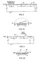
- a conventional membrane 10 of nitrocellulose of thickness t m of e.g. 12 to 15 micron is diagrammatically depicted upon the surface of a transparent, rigid support 12, e.g. a glass microscope slide of thickness t s of e.g. 1mm.
- the nitrocellulose layer of thickness t m is micro-porous in nature.
- biological material B of a deposit is shown to have migrated as the result of a spotting or other deposit technique.
- the biological material B deposited in a liquid suspension, migrates downwardly as the liquid is absorbed or progresses through the thickness of the membrane 10.
- the molecules of biological material bind to sites on the elements 10a of the substrate, see FIG. 1B , and are immobilized, while the carrier liquid disperses and evaporates.
- the depth of penetration t b of significant concentrations of biological material B depends upon factors such as degree of porosity of the nitrocellulose or other immobilizing membrane, size and configuration of the specific bio-material molecules in the suspension, overall viscosity of the liquid suspension, and method of deposit.
- depth of penetration t b of molecules B is substantially less than the overall thickness t m of the membrane, typically substantially less than half.
- the depth of penetration t b of significant quantities of the biological molecules is often of the order of one third or less than the thickness t m , e.g. t b is equal to 3 or 4 micron, though penetrations up to 6 or 7 micron at other times may be observed.
- immobilized molecules B 1 reside on the surface of a constituent element 10a of the micro-porous membrane.
- a fluorescently or luminenscently tagged molecule of reagent R t binds to molecule B 1 .
- an ultra-thin micro-porous immobilizing membrane 20, of thickness t ut e.g., of e.g. 2 to 3 micron
- the support 12 which again may be a glass microscope slide.
- Adhesion of the ultra-thin layer is enhanced by an intervening adhesion-promoting layer 14.
- Layer 14 may be, in the case of a glass support, silane or epoxy-silane (which offers a covalent bond to nitrocellulose and consequently is able to support a mono-layer of nitrocellulose molecules), or other common surface adhesion promoters such as PEI (Polyethylene imine), and GAP (gamma amino propylene).
- the fluorescent signal attributable to the tagged molecules will be equal in the two cases, but, because the volume of the nitrocellulose or other immobilizing substrate material, per unit area of FIG. 1A , is about four times greater than the volume per unit area of FIG. 2A , the self-fluorescent noise signal from the nitrocellulose or other immobilizing material will be significantly greater with the conventional prior art membrane of FIG. 1A . Even if the subtraction correction is employed, such correction is never perfect, the error generally being proportional to the size of the original error signal. Thus, improvement in corrected signal is obtainable with the embodiment of Figs. 2 and 2A .
- the continuous ultra-thin membrane of the embodiment of FIG. 2 and 2A is found to retain a key attribute of conventional much thicker nitrocellulose membranes of the prior art, that of enabling imaging the unoccupied membrane between spots to enable subtraction of a value representing detrimental background fluorescence. Therefore, it is seen that the embodiment of Figs. 2 and 2A has significant advantages over the spotted mixture approach recently proposed by Pinkel and by Audeh, et al., referred to earlier.
- a solid ultra-thin film of immobilizing substrate material 20' is formed by the techniques mentioned.
- an ultra-thin solid coating 20' of nitrocellulose or other protein-immobilizing polymer substrate material is formed of a thickness t uts of e.g. 0.1 to 0.5 micron.
- the resultant membrane being solid, i.e., substantially non porous, as well as being continuous in X, Y extent, presents a superficially planar array-receiving surface (albeit, as with any surface, the surface exhibits microscopic or submicroscopic roughness over which the binding sites of the material are distributed.)
- the embodiment of Figs. 3 and 3A also permits subtraction of background signal, and hence can represent a significant advantage over the Pinkel and Audeh et al., approach, as well as significant advantage over prior commercially available substrates.
- the substance of the ultra-thin substrate layer in both Figs. 2 and 3 is nitrocellulose suitable for immobilizing protein molecules such as viruses, peptides, antibodies, receptors, and other proteins or to a wide range of biological materials including, plant, animal, human, fungal and bacteria cell, cDNA, DNA probes, oligonucleotides, polymerase chain reactions (PCR) products, and chemicals.
- An ultra-thin substrate layer of polystyrene, according to the invention, is also particularly effective for such biological materials.
- glass slides 12 are exposed to vapor deposit conditions or sputter coating conditions for application of a metal-based coating, e.g., tantalum, which oxidizes to form tantalum oxide, or aluminum, which oxidizes to form aluminum oxide.
- a metal-based coating e.g., tantalum, which oxidizes to form tantalum oxide, or aluminum, which oxidizes to form aluminum oxide.
- the metal for the oxide coating applied e.g. by sputter coating can be of Angstrom range thickness.
- the metallizing conditions are determined according to the desired degree of transmissivity or opacity desired. Similar techniques are common in the design and production of optical coatings, to which reference is made. For present purposes, it has been shown that coatings 54 of tantalum, converted to tantalum oxide, that permit 90% transmission to almost no transmission have effective adhesion qualities for instance, to glass, to serve as the support 12, as well as to nitrocellulose and polystyrene, desirable materials for the bio-compatible substrate 56. At 70% transmission (blocking 30%) or less, e.g.
- an angstrom range thickness layer is effective to reduce or substantially eliminate from sensing in reflective mode, any fluorescence, luminescence or stray radiation that may originate in or enter through the substance of a glass microscope slide or other transparent, rigid support.
- the slides After application of such an oxide layer, or other adhesion promoting layer such as described below, or combination of such layers, the slides are stored in a controlled dry environment at room temperature, ready for the next step.
- the coatings described above ensure proper adhesion of the nitrocellulose or other ultra-thin immobilizing substrate polymer to the glass support 12.
- a number of other adhesion promoters can also be used, sodium silicate or colloidal silica presently being preferred among the alternatives.
- microscope slides coated with other adhesion promoters may be purchased from commercial houses such as Erie Scientific.
- an advantageous method of preparing thin-film or microporous membrane coated slides employs drawing slides from immersion in a polymeric solution. Generalized steps for the method are shown in FIG. 5 . Slides are prepared prior to immersion, are immersed and drawn from a polymeric solution, which is then followed in many advantageous cases by a post drawing surface treatment such as exposure to corona discharge, etc. As previously noted, the resultant coating is referred to herein as a "drawn" coating.
- the slide preparation can advantageously employ steps of applying one or more layers of adherence promoting layers and, as well, may employ surface treating the surface of the base support or one or more of the added layers to promote adhesion of the next layer.
- FIG. 6 illustrates the succession of preferred steps (with preferred alternatives) in a method used to prepare commercial glass slides for protein or nucleic acid processing. Alternative steps are indicated by dashed line in FIG. 6 .
- a slide is silk screened or coated with tantalum oxide, in preparation for marking and serialization.
- a silk-screened pattern 104 is applied. It covers the frosted side 102 of the slide 100 as well as providing any frame 106 that may be desired.
- a frame, tracing the outer periphery of the slide, may have a width of 1 to 3 mm (preferably 2 mm).
- the region over the frosted end 102 may be marked and serialized e.g. with a commercial laser marker.
- the peripheral frame may serve both for protection and aesthetic purposes.
- a uniform metal coating 112 e.g. of tantalum oxide, is applied by sputtering or vapor depositing atoms from a source 108 onto the slide 100 in a vacuum chamber 110. This is followed by air oxidation.
- the oxide coating thus prepared is preferably at least partially opaque and employed to permit laser marking and serialization, as well as serving as an efficient adhesion promoter.
- Laser ablation may also serve advantageously to separate the region to be spotted into a number of separate sub-regions. The ablation may be performed on a coated substrate, or performed on an adherence promoting layer that leads to segmentation of a fluid-applied layer, as later described.
- an opaque coating either the metal oxide, or other opaque layer applied e.g. by printing techniques, blocks light transmission between the support and the bio-material carrying substrate layer.
- an oxide coating 112 is omitted or applied very thinly and the object is laser-marked at the silk-screen pattern 104.
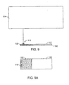
- FIG. 9 illustrates use of laser ablation 113 to mark the coating 112 over the frosted region 102 to serialize the slides 100 or add identification or registration markings 116 for automatic optical unit or information retrieval. Markings produced by laser ablation 113 may be used to enhance data acquisition reliability using various devices including, advantageously, commercial bar code readers.
- one ore more durable sensitivity and geometry calibration spots may be locally deposited on slide 100.
- reference spots may also be applied to the exterior surface of the substrate layer 20 or 20', here illustrated as in a pattern distributed across the array.
- Reference spots such as those at the corners of the array, may be employed as fiducial markings for geometrical reference, as by the imaging device.
- the same reference spots can serve as standards for the reading equipment to determine and accommodate long term variations in the optical instrumentation, such as light intensity or detector sensitivity. Likewise, they can be used to compensate for variation in illumination level over the area, e.g. to normalize the data across areas illuminated at different intensities.
- Temporally stable spotting material such as polyimide (Kapton) may be used as the calibration spots, deposited in solution in a solvent using a commercially available spot printer.
- the calibration compound is selected to have a broad fluorescence spectrum.
- Calibration markings 420 applied at the slide-manufacturing site, either below or on top of the substrate layer, can be employed in quality assurance steps whereby fluorescence of the ultra-thin film coated slides is measured following the final surface treatment step as indicated in FIG. 6 .
- fluorescence maybe measured from each unit or on a statistical sampling basis in accordance with quality control protocols.
- the slides are subsequently washed and, as shown in FIG. 12 , exposed to surface treatment to promote adhesion properties of the film or membrane.
- the slide 100 is translated under a jet of reactive species 124, e.g. ozone, produced by a corona treater 122 held at a distance d.
- reactive species 124 e.g. ozone
- a corona treater 122 held at a distance d.
- a suitable source of photons is used to process the surface, e.g. a UV laser beam may be moved across the surface in suitable raster scan.
- FIG. 13 immersion and drawing from a bath is employed for applying a layer to promote adhesion of the final substrate layer to be later applied.
- Drawing is preferably performed in a clean laboratory environment in a comfort humidity and temperature zone, preferably 33% humidity and 26°C.
- the cleaned and preferably recently (less than one day) corona treated slides 302 are immersed in a tank 300 of soluble silicate or colloidal silica, preferably a 3.3% solution of LUDOX CL from Sigma-Aldridge Co., and drawn out in the direction of the plane of the slide at a steady rate of approximately 0.5 in/ min.
- the result is a coating of uniform thickness that serves as an adhesion promoting layer.
- the tank 300 should be closed to avoid evaporation, and the liquid should be stirred a minimum of once per day.
- Slides not coated with metal oxide preferably receive such a silica-based coating. Slides with a metal oxide deposit may or may not receive such a coating.
- a number of slides 302 are suspended from a rack and processed simultaneously to apply the silica-based coating.
- the group of slides attached to a carriage 306, such as a one-axis, vibration-free carriage linear-transport from Sherline Products in Vista, CA., is translated, from the bath preferably at a uniform rate and between preset positions in a controlled manner.
- the slides thus coated with colloidal silica or silicate are air dried prior to being coated with the substrate layer material.
- the silica or silicate layer thus applied may be surface treated, e.g. according to FIG 12 , prior to application of the substrate layer.
- FIG. 14 shows a preferred embodiment of a coating station for application of the film or membrane substrate that is to receive the spotted array of biological material.
- the station is similar in construction and operation to the mechanism of FIG. 13 .
- the process is performed in a still environment (i.e., substantially no air currents or vibrations), in vibration-free conditions, with control parameters of temperature, humidity, and draw rate selected in accordance with the purposes of the composition and the desired coating thickness.
- Slides are immersed, then drawn from the bath as indicated in FIG. 14 .
- Figs. 15-18 diagrammatically illustrate aspects of the drawing process as well as post-drawing features. Slides 900 are shown edgewise along their thinnest dimension t (typically about 1mm for standard glass slides). Figs.
- 15 and 17 represent drawing an immersed slide 900 respectively from a thin film coating composition 902 and a microporous membrane coating composition 904.
- approximately 3 ⁇ 4 of the length of a slide 900 is immersed in the polymer composition 902 or 904, i.e. the portion intended to receive the spotted array.
- the polymeric compositions 902 and 904 adhere to the slides and form coatings 908 and 910 (stylized in the figures) on the surface of the slides 900.
- the newly formed coating composed of polymer and solvent begins to dry.
- the initial thickness of the wet coating is shown diagrammatically in Figs. 15 and 17 , comprising the sum of the resultant film thickness, t f or t mm , and thickness t v attributable to the volatile solvent.
- t f is much thinner than t mm by several orders of magnitude, indicated diagrammatically in Figs. 17 and 18 .
- slide 900 is shown broken away in Figs. 15-18 to emphasize the relative thinness of the film and microporous membrane structures.
- the dried coating may form lines of discontinuities or separation moats for purposes to be described later in reference to Figs. 23 and 24A-E , see especially moat M in FIG. 24C .
- the slides are subjected to surface modification with corona treatment (see FIG. 12 ) by translating the slide at a speed between 2 and 8 cm/min (preferably 4.4 cm/min) while maintaining the exposed surface to be treated normal and at a distance of between about 1 and 4 cm, (preferably 2 cm) from the jet of a standard 2.5 cm. round head of a corona treater, e.g. laboratory treater model BD-20AC from Electro-Technic Products Inc., of Chicago, 11 operating near its optimal level.
- a corona treater e.g. laboratory treater model BD-20AC from Electro-Technic Products Inc., of Chicago, 11 operating near its optimal level.
- the slides are transported between the various stations described by an operator or by suitable robots e.g. as part of standard commercial equipment or as part of a continuous production line.
- the coating process including drawing the adherence-promoting layer and drawing the substrate film or membrane, as well as the post-drawing treatment, are performed in a clean room or within a hood.
- the thus-formed substrate layers may also be subjected to other post forming treatments. For instance they may be treated to substrate-altering conditions, e.g. scanned under a laser or electron beam selected to provide porosity or otherwise to alter the overall bio-material binding characteristics or other structural features of the polymer membrane, such as for pore-forming with a laser or by an impinging fluid.
- substrate-altering conditions e.g. scanned under a laser or electron beam selected to provide porosity or otherwise to alter the overall bio-material binding characteristics or other structural features of the polymer membrane, such as for pore-forming with a laser or by an impinging fluid.
- the slides, when completed, may be packaged as single units or in multiples (such as 5 or 20 slides).
- the slides are ready to be spotted to form microarray A as shown in Figs. 11 , 19 , 22 and 23 .
- the techniques explained in U.S. Patent 6,269,846 which is hereby incorporated by reference in its entirety, may be used to form the array of spots 422.
- spots of reference material 420 may be strategically distributed throughout the array as suggested by Figs. 10, 11 , 22 and 23 .
- the array is subjected to assay conditions, such as are generally described in the above-cited Chin et al., patent. After washing they are ready to be imaged.
- imaging in a dark field reflectance mode may be accomplished with a CCD sensor 124 positioned to view the array along axis A normal to the plane of the array via collection optics 127, spaced a distance h from the substrate.
- the substrate layer may be microporous partially or throughout its depth or may be a solid film or a modified solid film.
- light for direct illumination enters along an illumination axis A', at an acute angle ⁇ to the plane of the array.
- Distance h must be selected to enable such direct illumination, with angle ⁇ ranging between about 20° and 50°, here shown at 45°.
- Light L originates from a source 112a, 112b or 112c of wavelength selected to excite the fluorophore tag of the array, passes via dichroic mirrors 156b, 156c to mirror 116 located to the side that directs the illumination along axis A' at angle ⁇ , onto the fluorophore-tagged array of spots resident on the ultra-thin substrate 20 or 20'.
- the fluorescent emissions are collected by lens 127, through a selected filter 128A, B or C, thence through lens 126 to CCD camera 124 under computer control 132.
- the background subtraction technique is used with this system.
- a confocal scanner imager 10 may also be employed.
- a confocal microscope may be constructed, for instance, according to Minsky, U.S. Patent 3,013,467 , or a scanning confocal microscope may be employed, such as the Affymetrix '428 Scanner, mentioned above.
- Such imagers may be in accordance with U.S. Patents 6,185,030 and 6,335,824 . The three patents of this paragraph are hereby incorporated by reference in their entireties.
- pin 400 which may be one of a set of simultaneously actuatable pins of a commercially available spot printer, is dipped into reference composition 440 held, for example, within one of the wells 442 of a microwell plate also being used for printing the biomaterial array.
- this particular well 400 holds a reference solution such as polyimide (Kapton) dissolved in a suitable solvent.
- a user-applied reference array is applied when spotting the array of biological material. (In other cases geometric reference spots or fiducials and intensity calibration spots may be applied during manufacture of the device, e.g. before or after applying the substrate layer.)
- Figs. 10,11 and 19 illustrate pin 400 contacting slide 100 to deposit composition 440 forming spot S.
- Typical diameters for spots 422 of biological material are 150 micron and 300 micron, and the same size spots may be used for the simultaneously-applied intensity calibration reference spots 420, using the previously mentioned synthetic resin material, such as a polyimide polymer (Kapton), which exhibits temporally stable broad fluorescence properties.
- Kapton polyimide polymer
- the same printer used to deposit the array 418 of biological material spots 422 may thus be used to deposit calibration spots 420 on the slide.
- the amount of material deposited for spots 420 is not critical since polymers such as Kapton are optically opaque, from which fluorescent emission 464 occurs at or near the surface, with the reproducible quantum yields.
- FIG. 21 shows a pre-spotted bio-cassette (cover not shown), having a protein-immobilizing substrate that may be offered to clinics, bearing a diagnostic protein array of spots 422 and intensity and/or registration calibration spots 420, see FIG 22 .
- the clinical laboratory may react a patient's fluid with the array to determine a disease condition.
- bio-immobilizing polymer may be applied to other surfaces such as by chemical vapor deposition upon the bottoms of wells of multi-well plates or to inside surfaces of hollow reaction tubes.
- a number of spotted micro arrays 418 are often placed upon the same microscope slide 10, intended to be reacted with different fluids, for different assays, for instance using extracts of blood from different subjects.
- a fluid-tight elastomeric gasket 430 in the form of a grid of upstanding walls 432, is pressed tightly against the face of the microscope slide. This defines individual wells at individual arrays 418.
- FIG. 24D Such an arrangement is shown in FIG. 24D , in which spotted arrays 418 are individually surrounded by walls 432 of the grid-form gasket 430 that is pressed tightly against the substrate layer 20" on the microscope slide surface.
- the gasket is removed, and the microscope slide placed beneath a microscope, its field of view suggested by the circle in FIG. 24E .
- the gasket sometimes adheres to the substrate layer more tenaciously than the substrate layer adheres to its support, and the substrate is lifted or disrupted. This can destroy readability of the micro arrays or introduce possibilities of error in their microscopic examination.
- a substrate layer 20 e.g. of nitrocellulose or polystyrene, is applied to a rigid support 12, as in the previous embodiments with an intervening adhesion promoting layer 14' being first applied to the rigid support, but in this instance, a pattern of disruptions or moats M is formed in the substrate layer 20", such that each portion of substrate on which an array is located is isolated from the portions of the substrate layer upon which the gasket walls press. It is found that a substrate layer so formed prevents the micro arrays from being disrupted when the gasket is removed.
- This segmentation may be achieved for instance by laser cutting or otherwise scoring a preformed continuous substrate layer to provide separation of the substrate of each array from adjoining substrate.
- the moats M are formed during formation of the substrate by a simple and inexpensive technique.
- the adhesion promoting layer is applied with a pattern of interruptions corresponding to the desired location of the moats M.
- the adhesion promoting layer is a metal oxide layer, this may be accomplished by metallizing the surface of the rigid support, as by sputter coating, through a grid-form mask, define lines in which no adhesion promoter reaches the rigid support, or by laser etching after metallization.
- FIGs. 25, 25A and 25B another system for producing an ultra-thin bio-immobilizing product is provided.
- Round, thin "CD" type discs 120 of relatively rigid material are formed at station A.
- This base support structure may be of PMMA or polystyrene.
- each automatically formed disc is introduced at station B to a vacuum chamber to receive a thin, adhesion promoting coating 121 of metal such as tantalum or aluminum, such as has been applied to semiconductor discs in the semiconductor industry.
- the coating is exposed to conditions forming an adherent oxide, e.g. tantalum oxide or aluminum oxide.
- the automatically formed discs 120 with adhesion promoting coating 121 are introduced to a spin coating station, C, formed of standard spinning equipment, e.g. from the semi-conductor industry.
- a layer of coating solution is either applied prior to introduction to each disc, or, as shown, is applied, first at slow rotation speed at the spin coating station, to the center of the disc, the disc being supported and spun from beneath.
- the so-coated disc is spun at high speed, to remove from the surface of the disc all of the solution except that thin layer that is retained by the inherent adhesion forces existing between the fluid and the metal oxide coating.
- the applied layer is dried.
- the formed layer may be subjected to a desired post-treatment, and then may be assembled with cover and other structure to complete a bio-cassette.
- FIG. 26 diagram of a composite is intended as a general illustration, e.g. to illustrate the cross-section of a planar microscope slide, a bio-cassette, a disc-form substrate, the bottom of a micro-well plate or other useful configuration for presenting material on a substrate for microscopic examination from the substrate side.
- a support 12 e.g. of glass of 1mm thickness, has a surface to which a thin adherent metal oxide layer 54 has been applied, in the example, tantalum oxide, as before.
- a bio-compatible substrate 56 e.g. of nitrocellulose or polystyrene, which may advantageously be of the ultra-thin dimension described above or, depending upon imaging requirements, may be thicker. Subsequently the bio-material spots are applied.
- a terminal 70 is associated with conductive layer 54'" underlying the substrate 56, and connected to a battery 72 or other controllable potential source.
- a controller, 74 e.g. a switch and rheostat, has settings #1 and #2, typically more.
- a positive electrical potential is applied to conductive layer 54"' of a level to increase the binding affinity of a target molecule as well as an accompanying molecule of lesser charge.
- the potential level may be changed to lower level, not shown, as by use of the rheostat.
- the target molecule remains bound, but binding force is so reduced or eliminated with respect to the accompanying molecule that it is washed away or otherwise detached from the substrate.
- the potential may be changed from positive to negative, setting #1, for use in situations where a selected negative potential will repel undesired molecules while still retaining the target molecule.
- a multiwell plate 90 is comprised of a bottomless upper structure 91 and a planar bottom glass plate member 95.
- the upper structure 91 is of extruded form, e.g., of polystyrene.
- an array of wells 92 is formed by a nest of tubular walls 94'.
- Other such honeycomb-type structures can be employed.
- wells of multiwell plates are intended to receive aliquots of unknowns and reagents, and fluorophore tags are excited and read by transmission of excitation light from an objective to and transmission of fluorescent radiation from the wells, across the transparent bottom plate, to an objective of a detection system.
- a layer of adherence-promoting material is applied on the bottom plate of glass (or a plate of polymer material such as polycarbonate also adhesively incompatible with polystyrene).
- the layer is formed in a pattern which matches the pattern of the lower edges 94a of the bottom-less upper structure 94 of the micro-well plate to be assembled.
- the layer is uniformly applied across the upper surface of bottom plate 95.
- the oxide coating is selected to be so thin as not to substantially impair light transmission qualities of the bottom plate.
- the portion of the applied layer beneath the lower edges facilitates the manufacture of the composite well-plate, as it enables the upper structure to be of material (e.g. polystyrene) that is adhesively incompatible with the bottom plate (e.g. glass).
- such an adhesively incompatible support plate 95 e.g. of glass for forming the bottom of a multi-well plate is uniformly coated with a film of an adhesion promoter 96, e.g. the tantalum oxide discussed, followed by application of a uniform upper film 97 of polystyrene or other substance that is adhesively compatible with the upper structure as well as suitable as a substrate for spots of bio-material.
- the bottom-less upper elements of the micro-well plate may thus be of polystyrene and joined to a uniformly coated glass.
- the union may be enhanced by heat or by the temporary presence of a solvent such as Amyl Acetate or the temporary presence of a solution of polystyrene in such a solvent.
- the glass surface, coated with a thin film of polystyrene may have its surface adhesion enhanced as described above, e.g. by corona treatment, to serve as a biomaterial receiving substrate at the bottom of the wells.
- the uniform film of polystyrene coated over the adhesion promoter on the glass plate may be an ultra-thin layer as previously described, and its areas within the grid of the multi-well plate may thus be suitable for receiving deposit of bio-molecules as previously discussed. Thus microscopic reading of the wells through the transparent bottom of the micro-well plate can be enhanced.
- a pattern 98 of tantalum oxide or other suitable mutually adherent composition is applied to the plate 95', matching the geometry of the grid 94.
- a material is applied, e.g. a composite of an adhesive promotion layer 56a of any of those mentioned, and a bio-receiving substrate 54a of any of those mentioned, see FIG. 34A .
- the composite may be an adherent oxide layer on the top of which a nitrocellulose or divinyl benzene substrate is applied.
Applications Claiming Priority (4)
| Application Number | Priority Date | Filing Date | Title |
|---|---|---|---|
| US40423702P | 2002-08-16 | 2002-08-16 | |
| US43029902P | 2002-12-02 | 2002-12-02 | |
| US47651203P | 2003-06-06 | 2003-06-06 | |
| EP03751862.8A EP1546721B2 (fr) | 2002-08-16 | 2003-08-18 | Substrats d'isolation, de reaction et d'analyse microscopique de matieres |
Related Parent Applications (2)
| Application Number | Title | Priority Date | Filing Date |
|---|---|---|---|
| EP03751862.8A Division-Into EP1546721B2 (fr) | 2002-08-16 | 2003-08-18 | Substrats d'isolation, de reaction et d'analyse microscopique de matieres |
| EP03751862.8 Division | 2003-08-18 |
Publications (1)
| Publication Number | Publication Date |
|---|---|
| EP2315027A1 true EP2315027A1 (fr) | 2011-04-27 |
Family
ID=31892097
Family Applications (3)
| Application Number | Title | Priority Date | Filing Date |
|---|---|---|---|
| EP03788571A Withdrawn EP1546723A4 (fr) | 2002-08-16 | 2003-08-18 | Lecture de reseaux fluorescents |
| EP03751862.8A Expired - Lifetime EP1546721B2 (fr) | 2002-08-16 | 2003-08-18 | Substrats d'isolation, de reaction et d'analyse microscopique de matieres |
| EP10184800A Withdrawn EP2315027A1 (fr) | 2002-08-16 | 2003-08-18 | Substrats pour isoler, pour réagir et pour analyser des matériaux au microscope |
Family Applications Before (2)
| Application Number | Title | Priority Date | Filing Date |
|---|---|---|---|
| EP03788571A Withdrawn EP1546723A4 (fr) | 2002-08-16 | 2003-08-18 | Lecture de reseaux fluorescents |
| EP03751862.8A Expired - Lifetime EP1546721B2 (fr) | 2002-08-16 | 2003-08-18 | Substrats d'isolation, de reaction et d'analyse microscopique de matieres |
Country Status (4)
| Country | Link |
|---|---|
| EP (3) | EP1546723A4 (fr) |
| JP (2) | JP2006515065A (fr) |
| AU (2) | AU2003269968A1 (fr) |
| WO (2) | WO2004017374A2 (fr) |
Cited By (1)
| Publication number | Priority date | Publication date | Assignee | Title |
|---|---|---|---|---|
| EP3951361A4 (fr) * | 2019-03-28 | 2022-11-16 | Hamamatsu Photonics K.K. | Dispositif d'observation de fluorescence |
Families Citing this family (80)
| Publication number | Priority date | Publication date | Assignee | Title |
|---|---|---|---|---|
| US7270960B2 (en) | 2001-08-29 | 2007-09-18 | Pacific Northwest Research Institute | Diagnosis of ovarian carcinomas |
| US20050046848A1 (en) * | 2003-08-26 | 2005-03-03 | Blueshift Biotechnologies, Inc. | Time dependent fluorescence measurements |
| BRPI0511003A (pt) | 2004-05-13 | 2007-11-20 | Applera Corp | estruturas de lámina compósita para ensaio micro analìtico, dispositivo compósito, e, método para fabricar um dispositivo compósito |
| EP1774024A4 (fr) | 2004-07-02 | 2012-04-04 | Blueshift Biotechnologies Inc | Exploration de micro-environnements des fluorophores |
| FR2873815B1 (fr) * | 2004-08-02 | 2006-11-24 | Inodiag Sa | Dispositif de lecture pour lames portant des micro depots supports de reaction biologique |
| US7615369B2 (en) * | 2004-09-22 | 2009-11-10 | The Regents Of The University Of Michigan | Reconfigurable protein patterning using electrowetting microelectrodes |
| US20060166305A1 (en) * | 2005-01-27 | 2006-07-27 | Genetix Limited | Animal cell confluence detection method and apparatus |
| WO2006132666A1 (fr) | 2005-06-06 | 2006-12-14 | Decision Biomarkers, Inc. | Epreuves fondees sur des agencements d'ecoulement liquide |
| JP4538746B2 (ja) * | 2005-09-21 | 2010-09-08 | 横河電機株式会社 | バイオチップおよび分析装置 |
| EP1801593A1 (fr) * | 2005-12-22 | 2007-06-27 | Koninklijke Philips Electronics N.V. | Une méthode d'imagérie d'échantillons biologiques au moyen des nanoparticules comme des agents de marquage |
| WO2007081768A2 (fr) * | 2006-01-04 | 2007-07-19 | Fujirebio America, Inc. | Utilisation de he4 et d'autres marqueurs biochimiques dans l'évaluation de cancers de l'ovaire |
| JP2009526993A (ja) * | 2006-02-15 | 2009-07-23 | リ−コール インコーポレーティッド | 分子撮像のための蛍光フィルタリングシステムおよび方法 |
| US7923054B2 (en) | 2006-04-19 | 2011-04-12 | Gore Enterprise Holdings, Inc. | Functional porous substrates for attaching biomolecules |
| EP2153211A4 (fr) * | 2007-05-02 | 2012-03-14 | Fluidyx Pty Ltd | Dispositif portatif de lecture d'une puce sur membrane à marquage fluorescent |
| WO2009039170A2 (fr) * | 2007-09-17 | 2009-03-26 | Gentel Biosurfaces, Inc. | Dosage de puce protéique intégré |
| US8623789B2 (en) * | 2009-09-21 | 2014-01-07 | Akonni Biosystems, Inc. | Integrated cartridge |
| JP5188228B2 (ja) * | 2008-03-25 | 2013-04-24 | 東洋鋼鈑株式会社 | 蛍光標識された生体関連分子の検出方法 |
| PT2291640T (pt) | 2008-05-20 | 2019-02-26 | Univ Health Network | Dispositivo e método para imagiologia e monitorização baseados em fluorescência |
| JP5139581B2 (ja) * | 2008-08-29 | 2013-02-06 | 紅電醫學科技股▲分▼有限公司 | 分析用ストリップ |
| WO2010121643A1 (fr) * | 2009-04-20 | 2010-10-28 | Agilent Technologies, Inc. | Identification de marqueurs d'étalonnage dans des canaux de détection multiples |
| US8835358B2 (en) | 2009-12-15 | 2014-09-16 | Cellular Research, Inc. | Digital counting of individual molecules by stochastic attachment of diverse labels |
| US9315857B2 (en) | 2009-12-15 | 2016-04-19 | Cellular Research, Inc. | Digital counting of individual molecules by stochastic attachment of diverse label-tags |
| WO2011143791A1 (fr) * | 2010-05-20 | 2011-11-24 | Honeywell International Inc. | Lecteur à microréseau basé sur la détection d'ondes évanescentes |
| JP2010281842A (ja) * | 2010-09-24 | 2010-12-16 | Yokogawa Electric Corp | 光量計測装置および光量計測方法 |
| JP2011017721A (ja) * | 2010-09-24 | 2011-01-27 | Yokogawa Electric Corp | 光量計測装置および光量計測方法 |
| CN102121898A (zh) * | 2011-01-19 | 2011-07-13 | 云南烟草科学研究院 | 一种近红外样品检测装置 |
| ITTO20110567A1 (it) | 2011-06-28 | 2012-12-29 | St Microelectronics Srl | Cartuccia per analisi biochimiche, sistema per analisi biochimiche e metodo per eseguire un processo biochimico |
| BR112014010718B1 (pt) | 2011-11-16 | 2020-12-22 | Becton, Dickinson And Company | métodos, sistemas, dispositivos e kits para detecção de analito em amostra |
| SG11201405274WA (en) | 2012-02-27 | 2014-10-30 | Cellular Res Inc | Compositions and kits for molecular counting |
| US11177020B2 (en) | 2012-02-27 | 2021-11-16 | The University Of North Carolina At Chapel Hill | Methods and uses for molecular tags |
| CN102927953B (zh) * | 2012-11-08 | 2015-06-10 | 西南石油大学 | 一种剪切流动下聚合物水力学尺寸的测试方法及其测试装置 |
| EP2943788B1 (fr) | 2013-01-11 | 2018-08-08 | Becton Dickinson and Company | Dispositif d'analyse hors laboratoire à bas coût |
| KR20230074639A (ko) | 2013-08-28 | 2023-05-30 | 벡톤 디킨슨 앤드 컴퍼니 | 대량의 동시 단일 세포 분석 |
| CN105745528A (zh) * | 2013-10-07 | 2016-07-06 | 赛卢拉研究公司 | 用于以数字方式对阵列上的特征进行计数的方法和系统 |
| BR112016009958B1 (pt) | 2013-11-06 | 2021-08-03 | Becton, Dickinson And Company | Dispositivo microfluídico, método, sistema e kit |
| JP6518245B2 (ja) | 2013-11-13 | 2019-05-22 | ベクトン・ディキンソン・アンド・カンパニーBecton, Dickinson And Company | 光学撮像システム及びそれを用いた方法 |
| US9541750B2 (en) | 2014-06-23 | 2017-01-10 | Li-Cor, Inc. | Telecentric, wide-field fluorescence scanning systems and methods |
| US11795423B2 (en) | 2014-06-26 | 2023-10-24 | The Trustees Of The University Of Pennsylvania | Micro-fabricated multi-well chips for long term automated imaging of C. elegans growth and behavior |
| CA2955976A1 (fr) | 2014-07-24 | 2016-01-28 | University Health Network | Collecte et analyse de donnees a des fins de diagnostic |
| ES2824700T3 (es) | 2015-02-19 | 2021-05-13 | Becton Dickinson Co | Análisis unicelular de alto rendimiento que combina información proteómica y genómica |
| ES2836802T3 (es) | 2015-02-27 | 2021-06-28 | Becton Dickinson Co | Códigos de barras moleculares espacialmente direccionables |
| WO2016160844A2 (fr) | 2015-03-30 | 2016-10-06 | Cellular Research, Inc. | Procédés et compositions pour codage à barres combinatoire |
| US11390914B2 (en) | 2015-04-23 | 2022-07-19 | Becton, Dickinson And Company | Methods and compositions for whole transcriptome amplification |
| WO2016196229A1 (fr) | 2015-06-01 | 2016-12-08 | Cellular Research, Inc. | Méthodes de quantification d'arn |
| CN108026524A (zh) | 2015-09-11 | 2018-05-11 | 赛卢拉研究公司 | 用于核酸文库标准化的方法和组合物 |
| US10379049B2 (en) | 2015-10-15 | 2019-08-13 | Lumos Diagnostics IP Pty Ltd | Device for reading an IVD assay |
| EP4224219A3 (fr) * | 2016-04-22 | 2023-08-30 | Illumina Inc | Dispositifs et compositions à base de structure photonique destinés à être utilisés dans l'imagerie luminescente de sites multiples à l'intérieur d'un pixel, et leurs procédés d'utilisation |
| JP6818346B2 (ja) * | 2016-04-28 | 2021-01-20 | 国立大学法人浜松医科大学 | 電子顕微鏡によるナノ粒子の直接的な同定・定量のための検出キットおよび方法 |
| CA3019589A1 (fr) | 2016-05-02 | 2017-11-09 | Cellular Research, Inc. | Codes a barres moleculaires precis |
| US10301677B2 (en) | 2016-05-25 | 2019-05-28 | Cellular Research, Inc. | Normalization of nucleic acid libraries |
| CN109074430B (zh) | 2016-05-26 | 2022-03-29 | 贝克顿迪金森公司 | 分子标记计数调整方法 |
| US10202641B2 (en) | 2016-05-31 | 2019-02-12 | Cellular Research, Inc. | Error correction in amplification of samples |
| US10640763B2 (en) | 2016-05-31 | 2020-05-05 | Cellular Research, Inc. | Molecular indexing of internal sequences |
| BR112018072475A2 (pt) * | 2016-07-15 | 2019-02-19 | Panasonic Intellectual Property Management Co., Ltd. | método para determinar se ou não uma amostra de teste possui fungo fitopatogênico |
| EP3510379B1 (fr) | 2016-09-08 | 2023-09-27 | PreSens - Precision Sensing GmbH | Procédé pour mesure de luminescence calibré et système associé |
| CA3034924A1 (fr) | 2016-09-26 | 2018-03-29 | Cellular Research, Inc. | Mesure d'expression de proteines a l'aide de reactifs avec des sequences d'oligonucleotides a code-barres |
| WO2018089378A1 (fr) | 2016-11-08 | 2018-05-17 | Cellular Research, Inc. | Procédés destinés à la classification de profil d'expression |
| SG11201903158RA (en) | 2016-11-08 | 2019-05-30 | Cellular Res Inc | Methods for cell label classification |
| EP3568677A4 (fr) * | 2017-01-10 | 2020-10-21 | Photoswitch Biosciences, Inc. | Systèmes et procédés de détection |
| JP7104048B2 (ja) | 2017-01-13 | 2022-07-20 | セルラー リサーチ, インコーポレイテッド | 流体チャネルの親水性コーティング |
| US11319583B2 (en) | 2017-02-01 | 2022-05-03 | Becton, Dickinson And Company | Selective amplification using blocking oligonucleotides |
| US10676779B2 (en) | 2017-06-05 | 2020-06-09 | Becton, Dickinson And Company | Sample indexing for single cells |
| WO2018230575A1 (fr) * | 2017-06-15 | 2018-12-20 | オリンパス株式会社 | Système de microscope |
| JP6994238B2 (ja) * | 2017-11-07 | 2022-01-14 | 村角工業株式会社 | 刻印フロストスライドガラス及びフロストスライドガラスの刻印方法 |
| EP3728636A1 (fr) | 2017-12-19 | 2020-10-28 | Becton, Dickinson and Company | Particules associées à des oligonucléotides |
| GB2571743A (en) * | 2018-03-07 | 2019-09-11 | Pop Bio Ltd | A method of capturing image data of a luminescent sample and apparatus for the same |
| EP4234717A3 (fr) | 2018-05-03 | 2023-11-01 | Becton, Dickinson and Company | Analyse multi-omique d'échantillons à haut débit |
| JP7358388B2 (ja) | 2018-05-03 | 2023-10-10 | ベクトン・ディキンソン・アンド・カンパニー | 反対側の転写物末端における分子バーコーディング |
| EP3861134A1 (fr) | 2018-10-01 | 2021-08-11 | Becton, Dickinson and Company | Détermination de séquences de transcripts 5 |
| CN112969789A (zh) | 2018-11-08 | 2021-06-15 | 贝克顿迪金森公司 | 使用随机引发的单细胞全转录组分析 |
| WO2020123384A1 (fr) | 2018-12-13 | 2020-06-18 | Cellular Research, Inc. | Extension sélective dans une analyse de transcriptome complet de cellule unique |
| US11371076B2 (en) | 2019-01-16 | 2022-06-28 | Becton, Dickinson And Company | Polymerase chain reaction normalization through primer titration |
| EP4242322A3 (fr) | 2019-01-23 | 2023-09-20 | Becton, Dickinson and Company | Oligonucléotides associés à des anticorps |
| WO2020214642A1 (fr) | 2019-04-19 | 2020-10-22 | Becton, Dickinson And Company | Procédés d'association de données phénotypiques et de données de séquençage monocellule |
| EP4004231A1 (fr) | 2019-07-22 | 2022-06-01 | Becton, Dickinson and Company | Dosage de séquençage par immunoprécipitation de la chromatine monocellulaire |
| US11773436B2 (en) | 2019-11-08 | 2023-10-03 | Becton, Dickinson And Company | Using random priming to obtain full-length V(D)J information for immune repertoire sequencing |
| CN115244184A (zh) | 2020-01-13 | 2022-10-25 | 贝克顿迪金森公司 | 用于定量蛋白和rna的方法和组合物 |
| US11661625B2 (en) | 2020-05-14 | 2023-05-30 | Becton, Dickinson And Company | Primers for immune repertoire profiling |
| US11932901B2 (en) | 2020-07-13 | 2024-03-19 | Becton, Dickinson And Company | Target enrichment using nucleic acid probes for scRNAseq |
| US11739443B2 (en) | 2020-11-20 | 2023-08-29 | Becton, Dickinson And Company | Profiling of highly expressed and lowly expressed proteins |
Citations (12)
| Publication number | Priority date | Publication date | Assignee | Title |
|---|---|---|---|---|
| US3013467A (en) | 1957-11-07 | 1961-12-19 | Minsky Marvin | Microscopy apparatus |
| EP0366241A2 (fr) * | 1988-10-04 | 1990-05-02 | Fisher Scientific Company | Dispositif avec surface adsorbante et méthode de fabrication |
| US4975366A (en) * | 1986-02-20 | 1990-12-04 | Fuji Photo Film Co., Ltd. | Multi-layered element for quantititative analysis of immuno reactant |
| US5552272A (en) * | 1993-06-10 | 1996-09-03 | Biostar, Inc. | Detection of an analyte by fluorescence using a thin film optical device |
| WO2000033078A1 (fr) * | 1998-12-01 | 2000-06-08 | Syntrix Biochip, Inc. | Revetements poreux porteurs de groupes de ligands |
| US6185030B1 (en) | 1998-03-20 | 2001-02-06 | James W. Overbeck | Wide field of view and high speed scanning microscopy |
| US6197599B1 (en) | 1998-07-30 | 2001-03-06 | Guorong Chin | Method to detect proteins |
| US6207369B1 (en) * | 1995-03-10 | 2001-03-27 | Meso Scale Technologies, Llc | Multi-array, multi-specific electrochemiluminescence testing |
| US6269846B1 (en) | 1998-01-13 | 2001-08-07 | Genetic Microsystems, Inc. | Depositing fluid specimens on substrates, resulting ordered arrays, techniques for deposition of arrays |
| US20020015958A1 (en) | 2000-05-04 | 2002-02-07 | Audeh Zuheir L. | Colloid compositions for solid phase biomolecular analytical, preparative and identification systems |
| US20020068157A1 (en) * | 2000-10-26 | 2002-06-06 | Glaucus Proteomics B.V. | Products with biofunctional coating |
| US20020085073A1 (en) * | 2000-12-28 | 2002-07-04 | Eastman Kodak Company | Ink jet apparatus having amplified asymmetric heating drop deflection |
Family Cites Families (30)
| Publication number | Priority date | Publication date | Assignee | Title |
|---|---|---|---|---|
| JPS61152700A (ja) * | 1984-12-26 | 1986-07-11 | Susumu Kogyo Kk | タンパク質固定用膜担体およびその製造法 |
| JPH079087Y2 (ja) * | 1987-04-13 | 1995-03-06 | 大日本印刷株式会社 | 検査シ−ト |
| JPS645486A (en) * | 1987-06-29 | 1989-01-10 | Hitachi Ltd | Cell culture method and apparatus therefor |
| JPH01240188A (ja) * | 1988-03-18 | 1989-09-25 | Fuji Photo Film Co Ltd | 機能性有機薄膜 |
| US5720928A (en) * | 1988-09-15 | 1998-02-24 | New York University | Image processing and analysis of individual nucleic acid molecules |
| US5491097A (en) * | 1989-06-15 | 1996-02-13 | Biocircuits Corporation | Analyte detection with multilayered bioelectronic conductivity sensors |
| AU6513790A (en) † | 1989-09-18 | 1991-04-18 | Biostar Medical Products, Inc. | Apparatus for detection of an immobilized analyte |
| JP2869866B2 (ja) * | 1989-10-06 | 1999-03-10 | ティーディーケイ株式会社 | 電気化学発光検出用容器 |
| US5096668A (en) * | 1990-04-26 | 1992-03-17 | Difco Laboratories | Diagnostic test slide |
| US5784162A (en) * | 1993-08-18 | 1998-07-21 | Applied Spectral Imaging Ltd. | Spectral bio-imaging methods for biological research, medical diagnostics and therapy |
| ES2123063T3 (es) * | 1992-09-14 | 1999-01-01 | Stanford Res Inst Int | Marcadores convertidores al alza para ensayos biologicos y otros mediante tecnicas de excitacion laser. |
| JP3144513B2 (ja) * | 1993-06-17 | 2001-03-12 | 富士写真フイルム株式会社 | 蛍光顕微鏡 |
| CN1192097C (zh) * | 1995-03-10 | 2005-03-09 | 梅索磅秤技术有限公司 | 多阵列、多特异性的电化学发光检验 |
| US6017496A (en) * | 1995-06-07 | 2000-01-25 | Irori | Matrices with memories and uses thereof |
| JPH0943147A (ja) * | 1995-07-28 | 1997-02-14 | Bunshi Bio Photonics Kenkyusho:Kk | 暗視野落射蛍光顕微鏡装置 |
| US6165798A (en) * | 1996-10-10 | 2000-12-26 | University Of British Columbia | Optical quantification of analytes in membranes |
| US6294327B1 (en) * | 1997-09-08 | 2001-09-25 | Affymetrix, Inc. | Apparatus and method for detecting samples labeled with material having strong light scattering properties, using reflection mode light and diffuse scattering |
| WO1999023466A2 (fr) * | 1997-10-31 | 1999-05-14 | Ljl Biosystems, Inc. | Appareil et procedes permettant de mesurer la polarisation de fluorescence |
| JPH11218690A (ja) * | 1998-02-04 | 1999-08-10 | Olympus Optical Co Ltd | 落射蛍光照明光学系を備えた顕微鏡 |
| US6406921B1 (en) * | 1998-07-14 | 2002-06-18 | Zyomyx, Incorporated | Protein arrays for high-throughput screening |
| WO2000033084A2 (fr) * | 1998-12-01 | 2000-06-08 | Syntrix Biochip, Inc. | Procedes et compositions permettant de former un reseau de reactions chimiques sur une surface support |
| JP2001215181A (ja) * | 2000-02-01 | 2001-08-10 | Fuji Photo Film Co Ltd | 顕微鏡観察用の高分子支持体 |
| CA2399163A1 (fr) * | 2000-02-18 | 2001-08-23 | Pall Corporation | Membranes |
| EP1264181B1 (fr) * | 2000-03-06 | 2007-06-06 | Dade Behring Marburg GmbH | Supports a revetement en polysaccharides, leur preparation et leur utilisation |
| JP2001235473A (ja) * | 2000-09-21 | 2001-08-31 | Biostar Inc | 固定化された分析物の検出装置 |
| US6905816B2 (en) * | 2000-11-27 | 2005-06-14 | Intelligent Medical Devices, Inc. | Clinically intelligent diagnostic devices and methods |
| EP1341934A4 (fr) * | 2000-12-12 | 2005-04-06 | Autogenomics Inc | Puce a adn amelioree |
| JP2002214232A (ja) * | 2001-01-12 | 2002-07-31 | Toray Ind Inc | 選択結合性物質固定化フィルム及びそれを用いた被検物質の測定方法 |
| US6573051B2 (en) * | 2001-03-09 | 2003-06-03 | Molecular Staging, Inc. | Open circle probes with intramolecular stem structures |
| EP2081396B1 (fr) † | 2006-11-03 | 2012-12-12 | Huawei Technologies Co., Ltd. | Procédé de communication mobile et entité d'accès |
-
2003
- 2003-08-18 WO PCT/US2003/025702 patent/WO2004017374A2/fr not_active Application Discontinuation
- 2003-08-18 EP EP03788571A patent/EP1546723A4/fr not_active Withdrawn
- 2003-08-18 AU AU2003269968A patent/AU2003269968A1/en not_active Abandoned
- 2003-08-18 JP JP2005502064A patent/JP2006515065A/ja active Pending
- 2003-08-18 JP JP2005501757A patent/JP4678516B2/ja not_active Expired - Fee Related
- 2003-08-18 EP EP03751862.8A patent/EP1546721B2/fr not_active Expired - Lifetime
- 2003-08-18 AU AU2003276852A patent/AU2003276852A1/en not_active Abandoned
- 2003-08-18 WO PCT/US2003/025685 patent/WO2004018623A2/fr active Application Filing
- 2003-08-18 EP EP10184800A patent/EP2315027A1/fr not_active Withdrawn
Patent Citations (13)
| Publication number | Priority date | Publication date | Assignee | Title |
|---|---|---|---|---|
| US3013467A (en) | 1957-11-07 | 1961-12-19 | Minsky Marvin | Microscopy apparatus |
| US4975366A (en) * | 1986-02-20 | 1990-12-04 | Fuji Photo Film Co., Ltd. | Multi-layered element for quantititative analysis of immuno reactant |
| EP0366241A2 (fr) * | 1988-10-04 | 1990-05-02 | Fisher Scientific Company | Dispositif avec surface adsorbante et méthode de fabrication |
| US5552272A (en) * | 1993-06-10 | 1996-09-03 | Biostar, Inc. | Detection of an analyte by fluorescence using a thin film optical device |
| US6207369B1 (en) * | 1995-03-10 | 2001-03-27 | Meso Scale Technologies, Llc | Multi-array, multi-specific electrochemiluminescence testing |
| US6269846B1 (en) | 1998-01-13 | 2001-08-07 | Genetic Microsystems, Inc. | Depositing fluid specimens on substrates, resulting ordered arrays, techniques for deposition of arrays |
| US6335824B1 (en) | 1998-03-20 | 2002-01-01 | Genetic Microsystems, Inc. | Wide field of view and high speed scanning microscopy |
| US6185030B1 (en) | 1998-03-20 | 2001-02-06 | James W. Overbeck | Wide field of view and high speed scanning microscopy |
| US6197599B1 (en) | 1998-07-30 | 2001-03-06 | Guorong Chin | Method to detect proteins |
| WO2000033078A1 (fr) * | 1998-12-01 | 2000-06-08 | Syntrix Biochip, Inc. | Revetements poreux porteurs de groupes de ligands |
| US20020015958A1 (en) | 2000-05-04 | 2002-02-07 | Audeh Zuheir L. | Colloid compositions for solid phase biomolecular analytical, preparative and identification systems |
| US20020068157A1 (en) * | 2000-10-26 | 2002-06-06 | Glaucus Proteomics B.V. | Products with biofunctional coating |
| US20020085073A1 (en) * | 2000-12-28 | 2002-07-04 | Eastman Kodak Company | Ink jet apparatus having amplified asymmetric heating drop deflection |
Non-Patent Citations (3)
| Title |
|---|
| E. FINSON AND STEPHEN L. KAPLAN: "Surface treatment", 1 January 1997 (1997-01-01), XP002626427, Retrieved from the Internet <URL:www.plasmatechsystems.com/about/pubs/surfacetreatment.asp> [retrieved on 20110302] * |
| PINKEL, NATURE GENETICS, vol. 20, October 1998 (1998-10-01) |
| ROBERT KESTING: "Synthetic Polymeric Membranes", 1971, MCGRAW-HILL |
Cited By (2)
| Publication number | Priority date | Publication date | Assignee | Title |
|---|---|---|---|---|
| EP3951361A4 (fr) * | 2019-03-28 | 2022-11-16 | Hamamatsu Photonics K.K. | Dispositif d'observation de fluorescence |
| US11921043B2 (en) | 2019-03-28 | 2024-03-05 | Hamamatsu Photonics K.K. | Fluorescence observation device |
Also Published As
| Publication number | Publication date |
|---|---|
| WO2004018623A3 (fr) | 2004-04-15 |
| EP1546721A2 (fr) | 2005-06-29 |
| EP1546721B2 (fr) | 2017-05-17 |
| JP2005535909A (ja) | 2005-11-24 |
| AU2003269968A1 (en) | 2004-03-11 |
| AU2003269968A8 (en) | 2004-03-11 |
| AU2003276852A1 (en) | 2004-03-03 |
| EP1546723A4 (fr) | 2007-03-07 |
| WO2004017374A2 (fr) | 2004-02-26 |
| JP2006515065A (ja) | 2006-05-18 |
| EP1546721A4 (fr) | 2006-10-18 |
| WO2004017374A3 (fr) | 2004-06-10 |
| EP1546723A2 (fr) | 2005-06-29 |
| EP1546721B1 (fr) | 2012-08-01 |
| WO2004018623A2 (fr) | 2004-03-04 |
| AU2003276852A8 (en) | 2004-03-03 |
| JP4678516B2 (ja) | 2011-04-27 |
Similar Documents
| Publication | Publication Date | Title |
|---|---|---|
| US7297497B2 (en) | Substrates for isolating, reacting and microscopically analyzing materials | |
| EP1546721B1 (fr) | Substrats d'isolation, de reaction et d'analyse microscopique de matieres | |
| AU713388B2 (en) | Device and apparatus for the simultaneous detection of multiple analytes | |
| US6653151B2 (en) | Dry deposition of materials for microarrays using matrix displacement | |
| US7258837B2 (en) | Microfluidic device and surface decoration process for solid phase affinity binding assays | |
| US6846635B1 (en) | Microarrays and their manufacture | |
| EP0874242B1 (fr) | Dispositif et appareil pour la détection simultanée de plusieurs analytes | |
| JP6297065B2 (ja) | 低蛍光器具 | |
| US6756014B2 (en) | Biochemical sensor and biochemical testing system using the same | |
| WO2002010761A1 (fr) | Microreseaux et leur fabrication par tranchage | |
| KR20150117110A (ko) | 랩온어칩 및 이의 제조 방법 | |
| EP1460424A2 (fr) | Appareil d'analyse biochimique | |
| Shiue et al. | Preparation of substrates for microarray protein chips with different ending functional groups | |
| EP1530723A1 (fr) | Microreseau 3d |
Legal Events
| Date | Code | Title | Description |
|---|---|---|---|
| PUAI | Public reference made under article 153(3) epc to a published international application that has entered the european phase |
Free format text: ORIGINAL CODE: 0009012 |
|
| AC | Divisional application: reference to earlier application |
Ref document number: 1546721 Country of ref document: EP Kind code of ref document: P |
|
| AK | Designated contracting states |
Kind code of ref document: A1 Designated state(s): CH DE FR GB LI |
|
| RIN1 | Information on inventor provided before grant (corrected) |
Inventor name: MONTAGU, JEAN I. Inventor name: ROOT, DAVID Inventor name: DOWD, ROGER |
|
| 17P | Request for examination filed |
Effective date: 20111026 |
|
| STAA | Information on the status of an ep patent application or granted ep patent |
Free format text: STATUS: THE APPLICATION IS DEEMED TO BE WITHDRAWN |
|
| 18D | Application deemed to be withdrawn |
Effective date: 20111028 |