EP2301788A2 - Gaspedalvorrichtung - Google Patents
Gaspedalvorrichtung Download PDFInfo
- Publication number
- EP2301788A2 EP2301788A2 EP10177933A EP10177933A EP2301788A2 EP 2301788 A2 EP2301788 A2 EP 2301788A2 EP 10177933 A EP10177933 A EP 10177933A EP 10177933 A EP10177933 A EP 10177933A EP 2301788 A2 EP2301788 A2 EP 2301788A2
- Authority
- EP
- European Patent Office
- Prior art keywords
- pedal arm
- arm
- pedal
- axis line
- rotation axis
- Prior art date
- Legal status (The legal status is an assumption and is not a legal conclusion. Google has not performed a legal analysis and makes no representation as to the accuracy of the status listed.)
- Granted
Links
- 238000006243 chemical reaction Methods 0.000 claims abstract description 35
- 230000007246 mechanism Effects 0.000 claims abstract description 28
- 238000005096 rolling process Methods 0.000 claims description 2
- 230000004044 response Effects 0.000 abstract description 7
- 230000009467 reduction Effects 0.000 description 11
- 239000000446 fuel Substances 0.000 description 6
- 230000006872 improvement Effects 0.000 description 5
- 230000006835 compression Effects 0.000 description 3
- 238000007906 compression Methods 0.000 description 3
- 230000000881 depressing effect Effects 0.000 description 3
- 230000003213 activating effect Effects 0.000 description 2
- 239000000696 magnetic material Substances 0.000 description 2
- 239000000463 material Substances 0.000 description 2
- 239000011347 resin Substances 0.000 description 2
- 229920005989 resin Polymers 0.000 description 2
- 238000004904 shortening Methods 0.000 description 2
- 229910000639 Spring steel Inorganic materials 0.000 description 1
- 230000002776 aggregation Effects 0.000 description 1
- 238000004220 aggregation Methods 0.000 description 1
- 238000005452 bending Methods 0.000 description 1
- 230000000994 depressogenic effect Effects 0.000 description 1
- 238000001514 detection method Methods 0.000 description 1
- 238000006073 displacement reaction Methods 0.000 description 1
- 238000005516 engineering process Methods 0.000 description 1
- 230000004907 flux Effects 0.000 description 1
- 230000007257 malfunction Effects 0.000 description 1
- 230000004048 modification Effects 0.000 description 1
- 238000012986 modification Methods 0.000 description 1
- 230000002035 prolonged effect Effects 0.000 description 1
- 230000001629 suppression Effects 0.000 description 1
Images


Classifications
-
- B—PERFORMING OPERATIONS; TRANSPORTING
- B60—VEHICLES IN GENERAL
- B60K—ARRANGEMENT OR MOUNTING OF PROPULSION UNITS OR OF TRANSMISSIONS IN VEHICLES; ARRANGEMENT OR MOUNTING OF PLURAL DIVERSE PRIME-MOVERS IN VEHICLES; AUXILIARY DRIVES FOR VEHICLES; INSTRUMENTATION OR DASHBOARDS FOR VEHICLES; ARRANGEMENTS IN CONNECTION WITH COOLING, AIR INTAKE, GAS EXHAUST OR FUEL SUPPLY OF PROPULSION UNITS IN VEHICLES
- B60K26/00—Arrangements or mounting of propulsion unit control devices in vehicles
- B60K26/02—Arrangements or mounting of propulsion unit control devices in vehicles of initiating means or elements
- B60K26/021—Arrangements or mounting of propulsion unit control devices in vehicles of initiating means or elements with means for providing feel, e.g. by changing pedal force characteristics
-
- G—PHYSICS
- G05—CONTROLLING; REGULATING
- G05G—CONTROL DEVICES OR SYSTEMS INSOFAR AS CHARACTERISED BY MECHANICAL FEATURES ONLY
- G05G5/00—Means for preventing, limiting or returning the movements of parts of a control mechanism, e.g. locking controlling member
- G05G5/03—Means for enhancing the operator's awareness of arrival of the controlling member at a command or datum position; Providing feel, e.g. means for creating a counterforce
-
- G—PHYSICS
- G05—CONTROLLING; REGULATING
- G05G—CONTROL DEVICES OR SYSTEMS INSOFAR AS CHARACTERISED BY MECHANICAL FEATURES ONLY
- G05G1/00—Controlling members, e.g. knobs or handles; Assemblies or arrangements thereof; Indicating position of controlling members
- G05G1/30—Controlling members actuated by foot
- G05G1/44—Controlling members actuated by foot pivoting
-
- Y—GENERAL TAGGING OF NEW TECHNOLOGICAL DEVELOPMENTS; GENERAL TAGGING OF CROSS-SECTIONAL TECHNOLOGIES SPANNING OVER SEVERAL SECTIONS OF THE IPC; TECHNICAL SUBJECTS COVERED BY FORMER USPC CROSS-REFERENCE ART COLLECTIONS [XRACs] AND DIGESTS
- Y10—TECHNICAL SUBJECTS COVERED BY FORMER USPC
- Y10T—TECHNICAL SUBJECTS COVERED BY FORMER US CLASSIFICATION
- Y10T74/00—Machine element or mechanism
- Y10T74/20—Control lever and linkage systems
- Y10T74/20528—Foot operated
- Y10T74/20534—Accelerator
Definitions
- the present invention relates to an accelerator pedal apparatus applied to vehicles and the like having a drive-by-wire system, and in particular, relates to an accelerator pedal apparatus capable of performing active control to generate reaction force (i.e., resistance force or press-back force) against tread force of a pedal arm for danger avoidance, danger notification, fuel consumption improvement, and the like.
- reaction force i.e., resistance force or press-back force
- An accelerator pedal apparatus adopted to an electronically controlled throttle system (i.e., a drive-by-wire system) for an engine mounted on an automobile and the like includes a pedal arm (i.e., a pedal element) being rotatably supported to a housing (i.e., a pedal holding member) between a rest position and a maximum depression position while integrally having an accelerator pedal, an active control mechanism to control the accelerator pedal so as to be pressed-back against depression operation of a driver as being contacted to an upper end portion of the pedal arm, and the like.
- a pedal arm i.e., a pedal element
- a housing i.e., a pedal holding member
- the active control mechanism disclosed in Japanese Patent Laid-open 2007-526177 includes a movable operation member (i.e., an operation push rod, a bowl-shaped yoke, and a ring-shaped magnet) linearly reciprocating in the approximate horizontal direction, a bowl-shaped coil bearing member fixed to the housing to exert electromagnetic drive force to the movable operation member, a coil wound around the coil bearing member, a spring urging the movable operation member so that the movable operation member (i.e., the operation push-rod thereof) is continuously contacted to the top end portion of the pedal arm, and the like.
- a movable operation member i.e., an operation push rod, a bowl-shaped yoke, and a ring-shaped magnet
- the active control mechanism adopts a solenoid type electromagnetic drive system as a drive source.
- the movable operation member contacted to the top end portion of the pedal arm is shaped elongated to reciprocate linearly in the approximate horizontal direction, so that the apparatus is upsized in the horizontal direction.
- the movable operation member transmits the electromagnetic drive force due to the solenoid type directly to the top end portion of the pedal arm. Therefore, variation in the electromagnetic drive force is directly transmitted to the pedal arm to cause a fear that stable active control operation cannot be performed.
- the spring included in the active control mechanism is utilized for a return spring to return the pedal arm toward the rest position. Therefore, when the movable operation member is fixed to be non-movable in a state that the spring is compressed, there is a fear that the pedal arm cannot be returned completely to the rest position.
- another accelerator pedal apparatus includes a pedal arm (i.e., a pedal element) being rotatably supported to a housing between a rest position and a maximum depression position while integrally having an accelerator pedal, an active control mechanism to control the accelerator pedal so as to press back against depression operation of a driver as being contacted to an upper end portion of the pedal arm, and then, the active control mechanism includes a plunger element linearly reciprocating in the approximate horizontal direction, a torque motor exerting reciprocating drive force to the plunger element, a coil spring urging the plunger element to be continuously contacted to the top end portion of the pedal arm, and the like (see German Patent Laid-open DE102004025829A1 ).
- the plunger element contacted to the top end portion of the pedal arm is shaped elongated to reciprocate linearly in the approximate horizontal direction, so that the apparatus is upsized in the horizontal direction.
- a rotation type torque motor is adopted as a drive source of the plunger element and the rotational drive force of the torque motor is converted into linear drive force of the plunger element via a pin to set arm length of the rotation torque to be approximately constant. Therefore, variation in the drive force (i.e., the torque) within the operational range of the torque motor is directly transmitted to the pedal arm via the plunger element to cause a fear that stable active control operation cannot be performed.
- the spring included in the active control mechanism is utilized for a return spring to return the pedal arm toward the rest position. Therefore, when the plunger element is fixed to be non-movable in a state that the spring is compressed, there is a fear that the pedal arm cannot be returned completely to the rest position.
- the present invention provides an accelerator pedal apparatus capable of performing active control with quick response while achieving structural simplification, parts count reduction, cost reduction, entire apparatus miniaturization, and the like.
- An accelerator pedal apparatus of the present invention includes a pedal arm interlocked with an accelerator pedal, a housing to support the pedal arm between a rest position and a maximum depression position as being rotatable around a first rotation axis line, a return spring to return the pedal arm toward the rest position, and a reaction force adding mechanism which includes a drive source arranged at the housing and a rotation member having a contact portion being contacted detachably attachable to the pedal arm and being rotated around a second rotation axis line in the same direction as the pedal arm in a state of being contacted to the pedal arm and in which the rotation member adds reaction force in the direction to return the pedal arm to the rest position with drive force of the drive source.
- first distance from a contact position of the pedal arm with the contact portion to the first rotation axis line is formed longer than second distance from the contact position of the pedal arm with the contact portion to the second rotation axis line
- the pedal arm includes a contact section formed so that the contact portion is displaced to be farther from the first rotation axis line while being contacted to the contact section when the pedal arm is rotated toward the maximum depression position and so that the contact portion is displaced to be closer to the first rotation axis line while being contacted to the contact section when the pedal arm is rotated toward the rest position.
- reaction force i.e., resistance force or press-back force
- tread force i.e., the driver
- the pedal arm is reliably returned to the rest position with urging force of the return spring.
- the reaction force adding mechanism is configured to include the drive source and the rotation member having the contact portion being contacted detachably attachable to the pedal arm and being rotated in the same direction as the pedal arm in a state of being contacted to the pedal arm, and then, is configured that the rotation member adds reaction force in the direction to return the pedal arm to the rest position with drive force of the drive source. Accordingly, active control with quick response can be performed while achieving structural simplification, parts count reduction, cost reduction, entire apparatus miniaturization, and the like.
- the first distance from the contact position of the pedal arm with the contact portion of the rotation member to the first rotation axis line of the pedal arm is formed longer than the second distance from the contact position of the pedal arm with the contact portion of the rotation member to the second rotation axis line of the rotation member.
- the pedal arm includes the contact section formed so that the contact portion is displaced to be farther from the first rotation axis line while being contacted to the contact section when the pedal arm is rotated toward the maximum depression position and so that the contact portions is displaced to be closer to the first rotation axis line while being contacted to the contact section when the pedal arm is rotated toward the rest position. Accordingly, the operational angle can be widened as shortening arm length of rotation torque exerted to the pedal arm by the rotation member. Therefore, stable drive force, that is, reaction force (i.e., resistance force) can be generated while achieving miniaturization of the drive source and the entire apparatus.
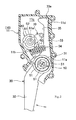
- the accelerator pedal apparatus includes a housing 10 fixed to a vehicle body of an automobile and the like, an accelerator pedal 20 supported swingably to a floor face F of the vehicle body, a pedal arm 30 supported rotatably having a predetermined first rotation axis line S1 defined by the housing 10 as the center between a rest position to a maximum depression position (i.e., a rotation range) while being interlocked with the accelerator pedal 20, a return spring 40 to exert urging force to return the pedal arm 30 toward the rest position, a position sensor 50 to detect a rotational angle position of the pedal arm 30, a drive source 60 and a rotation member 70 being rotatable around a second rotation axis line S2 defined by a drive shaft 61a of the drive source 60 while having a contact portion 71 to contact to the pedal arm 30 (i.e., a contact section 35 thereof) as a reaction force adding mechanism to add reaction force in the direction
- the housing 10 is formed of resin material as a whole. As illustrated in FIGs. 1 and 2 , the housing 10 is constituted with a housing main body 11 and a housing cover 12 which are mutually coupled with screws. As illustrated in FIG. 2 , the housing main body 11 includes a support shaft 11 a to support the pedal arm 30 rotatably around the first rotation axis line S1, a receiving portion 11 b to receive one end part of the return spring 40, a concave portion 11c to accommodate a part of the pedal arm 30 and the rotation member 70 and the drive source 60, a rest stopper 11d to stop the pedal arm 30 at the rest position, and the like. As illustrated in FIG. 1 , the housing cover 12 includes an accommodating portion 12a to accommodate the drive source 60, a sensor accommodating portion 12b to accommodate the position sensor 50, a cover portion 12c to cover the control unit 80, and the like.
- the accelerator pedal 20 is connected to the pedal arm 30 (i.e., a pedal side arm 32 thereof) via a link member 21 connected to the rear face of the upper section thereof having the lower end portion connected swingably to the floor face F. Further, the accelerator pedal 20 has a full-open stopper 22 to be contacted to the floor face F to define the maximum depressing position of the pedal arm 30.
- the pedal arm 30 is formed of resin material as a whole. As illustrated in FIGs. 1 to 3 , the pedal arm 30 includes a cylindrical portion 31 rotatably supported by the support shaft 11a of the housing 10 (defining the first rotation axis line S1), the pedal side arm 32 integrally formed as extending downward (i.e., to one side) from the cylindrical portion 31 (i.e., the first rotation axis line S1), a contact side arm 33 integrally formed as extending upward (i.e.
- a receiving portion 34 to receive the other end part of the return spring 40 formed at the front face side of the contact side arm 33 as being closer to the cylindrical portion 31, the contact section 35 formed at the front face side in a range between the receiving portion 34 and an upper end portion 33a of the contact side arm 33 to which the contact portion 71 of the rotation member 70 is contacted, and the like.
- the pedal arm 30 is rotatable around the first rotation axis line S1 as the cylindrical portion 31 being fitted to the support shaft 11a of the housing 10. Further, the lower end portion of the pedal side arm 32 is connected to the link member 21, as illustrated in FIG. 1 . Further, as illustrated in FIGs. 2 and 4 , the pedal arm 30 is rotatable in a rotation range between the rest position where the upper end portion 33a contacts to the rest stopper 11d and the maximum depression position where the full-open stopper 22 contacts to the floor face F. As illustrated in FIG.
- the contact section 35 is formed to define a cam profile so that the contact portion 71 of the rotation member 70 is displaced to be farther from the first rotation axis line S1 while being contacted to the contact section 35 when the pedal arm 30 is rotated toward the maximum depression position and so that the contact portion 71 of the rotation member 70 is displaced to be closer to the first rotation axis line S1 while being contacted to the contact section 35 when the pedal arm 30 is rotated toward the rest position.
- the return spring 40 is a compression type coil spring formed of spring steel and the like. As illustrated in FIGs. 2 and 4 , the return spring 40 is arranged in a state of being compressed to have a predetermined compression amount as the one end part thereof being engaged with the receiving portion 11 b of the housing 10 and the other end part thereof being directly engaged with the receiving portion 34 of the pedal arm 30. Accordingly, the return spring 40 directly exerts urging force to the pedal arm 30 to return toward the rest position. Therefore, even in the case that the reaction force adding mechanism (i.e., the drive source 60 and the rotation member 70) becomes non-movable as being fixed at some midpoint, the pedal arm 30 can be reliably returned to the rest position by the urging force of the return spring 40 when tread force is released.
- the reaction force adding mechanism i.e., the drive source 60 and the rotation member 70
- the position sensor 50 is arranged in the cylindrical portion 31 of the pedal arm 30 and the sensor accommodating portion 12b of the housing cover 12 at the area around the first rotation axis line S1.
- the position sensor 50 is a non-contact type magnetic sensor, for example, and is provided with a circular armature (not illustrated) made of magnetic material arranged at the area of the cylindrical portion 31 of the pedal arm 30, a pair of arc-shaped permanent magnets 51 connected to an inner circumferential face of the armature, two stators (not illustrated) made of magnetic material embedded in the housing cover 12, two hall elements (not illustrated) arranged between the two stators, and the like.
- a circuit board having terminals and various electronic parts mounted is provided as a part relating thereto. Then, when the pedal arm 30 is rotated, the position sensor 50 detects variation of magnetic flux density with the hall elements and outputs as a voltage signal. In this manner, the angular position of the pedal arm 30 is detected.
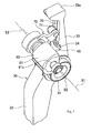
- the drive source 60 is a torque motor including a rotor 61 having the drive shaft 61a defining the second rotation axis line S2 (i.e., the drive shaft 61a being coaxial to the second rotation axis line S2) at the vicinity of the contact side arm 33 of the pedal arm 30 in the upper area from the first rotation axis line S1 of the pedal arm 30. Further, the drive source 60 is provided with an angle sensor (not illustrated) to detect the rotation angle of the rotor 61 (i.e., the rotation member 70).
- the rotor 61 of the drive source 60 is configured to be rotated in an angular range (i.e., the operational angle) between a rest angle ⁇ 0 corresponding to when the pedal arm 30 is located at the rest position and a maximum rotation angle ⁇ max corresponding to when the pedal arm 30 is located at the maximum depression position via an intermediate angle ⁇ m corresponding to when the pedal arm 30 is located at an intermediate depression position.
- the rotor 61 integrally rotates the rotation member 70 as directly connecting one end part of the rotation member 70 to the drive shaft 61a.
- the characteristics of the rotational drive force (i.e., the motor torque) of the drive source 60 (i.e., the torque motor) against the rotation angle indicate that values in a range of the small motor rotation angle corresponding to the rest angle ⁇ 0 and in a range of the large motor rotation angle corresponding to the maximum rotation angle ⁇ max are smaller than a value in an intermediate rotation range of the motor rotation angle corresponding to the intermediate angle ⁇ m .
- the rotation member 70 is formed to be a lever-shaped rotation lever by bending a plate-shaped metallic member.
- the rotation member 70 is directly connected to the drive shaft 61a of the drive source 60 at one end part thereof and includes the contact portion 71 having a roller contacted to the pedal arm 30 (i.e., the contact section 35 thereof) being detachably attachable at the free end part.
- the rotation member 70 is rotatable around the second rotation axis line S2 (i.e., the drive shaft 61a) so as to be rotated in the same direction as the pedal arm 30 in a state that the contact portion (i.e., the roller) 71 is contacted to the contact section 35 of the pedal arm 30.
- the rotation member 70 When the drive source 60 does not exert rotational drive force (i.e., rotational torque), the rotation member (i.e., the rotation lever) 70 is rotated to follow the rotation of the pedal arm 30, that is, to follow freely without exerting resistance force against movement of the contact side arm 33 in a state that the contact portion 71 is contacted to the contact section 35. Meanwhile, when the drive source 60 exerts rotational drive force (i.e., rotational torque), the rotation member 70 exerts reaction force (i.e., resistance force or press-back force) in the direction to return the pedal arm 30 to the rest position against the tread force.
- rotational drive force i.e., rotational torque
- reaction force i.e., resistance force or press-back force
- the rotation member 70 exerts reaction force (i.e., resistance force or press-back force) as rotating in the same direction as the rotation direction of the pedal arm 30 toward the rest position, the first rotation axis line S 1 of the pedal arm 30 and the second rotation axis line S2 of the rotation member 70 can be arranged to be mutually closed. Accordingly, aggregation of the structure and miniaturization of the apparatus can be achieved.
- the contact portion 71 of the rotation member 70 includes the rolling roller as being contacted to the contact section 35, so that the rotation member (i.e., the rotation lever) 70 is contacted to the contact section 3 5 of the pedal arm 30 via the roller. Accordingly, friction and resistance at the contact boundary face can be suppressed and energy loss can be reduced, so that active control can be performed effectively and smoothly.
- the drive source 60 is a torque motor having the drive shaft 61a being integrally rotated coaxially to the second rotation axis line S2.
- the rotation member 70 is a rotation lever defining the contact portion 71 at the free end thereof.
- the torque motor being the drive source 60 is a direct-drive type to directly rotate the rotation lever being the rotation member 70. Accordingly, structural simplification can be achieved due to reduction of a parts count and the rotational drive force of the torque motor (i.e., the drive source 60) can be effectively converted into the rotation torque of the rotation lever (i.e., the rotation member 70) with little loss.
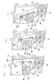
- first distance D1 from a position P at which the contact portion 71 is contacted to the pedal arm 30 (i.e., the contact section 35 thereof) to the first rotation axis line S1 is formed (i.e., arranged) to be longer than second distance D2 from the position P at which the contact portion 71 is contacted to the pedal arm 30 (i.e., the contact section 35 thereof) to the second rotation axis line S2. Further, as illustrated in FIG.
- the contact portion 71 is displaced to be farther from the first rotation axis line S 1 while maintaining the contact when the pedal arm 30 is rotated toward the maximum depression position (from the rest position) and that the contact portion 71 is displaced to be closer to the first rotation axis line S1 while maintaining the contact when the pedal arm 30 is rotated toward the rest position (from the maximum depression position). That is, the contact section 35 of the pedal arm 30 is formed to have a cam profile shape to cause the abovementioned displacement of the contact portion 71. According to the above arrangement configuration, the operational angle can be widened as shortening arm length of rotation torque exerted to the pedal arm 30 by the rotation member 70. Therefore, stable drive force, that is, reaction force (i.e., resistance force or press-back force) can be generated while achieving miniaturization of the drive source and the entire apparatus.
- reaction force i.e., resistance force or press-back force
- the contact section 35 of the pedal arm 30 is formed so that arm length R from the second rotation axis line S2 to a normal line N at the position P to which the contact portion 71 contacts varies in a rotation range between the rest position and the maximum depression position.
- the arm length R of rotation torque exerted to the pedal arm 30 by the rotation member 70 varies corresponding to the rotation range of the pedal arm 30.
- the arm length R is shortened in a range where drive force of the drive source 60 is small and the arm length R is prolonged in a range where drive force of the drive source 60 is large, for example. Accordingly, reliable active control having quick response can be performed without a fear that the rotation member 70 becomes difficult to be operated due to excessive load.
- the contact section 35 of the pedal arm 30 is formed so that the arm length R at the vicinities of both ends of the rotation range as illustrated in FIGs. 5A and 5C (i.e., the vicinity of the rest position and the vicinity of the maximum depression position) is shorter than the arm length R at the vicinity of a midpoint of the rotation range as illustrated in FIG. 5B .
- the rotation member in the case that drive force of the drive source is small in an operation area corresponding to vicinities of both ends of a rotation range between the rest position and the maximum depression position and is large in an operation area corresponding to an intermediate area of the rotation range, the rotation member can be smoothly rotated without causing excessive load in the operation area corresponding to the vicinities of the both ends and large reaction force or press-back force can be obtained in accordance with the drive force in the operation area corresponding to the intermediate area.
- the control unit 80 is to control driving of the drive source 60 of the reaction force adding mechanism. As illustrated in FIG. 1 , the control unit 80 is attached to the inside of a cover portion 12c of the housing cover 12. By integrating the control unit 80 with the housing 10 as mentioned above, wiring and the like are shortened and reliability is enhanced. Further, the accelerator pedal apparatus having a mechanism (i.e., the reaction force adding mechanism) capable of performing active control can be easily mounted without accompanying major modification at the vehicle side.
- a mechanism i.e., the reaction force adding mechanism
- reaction force i.e., resistance force or press-back force
- tread force i.e., resistance force or press-back force
- the pedal arm is reliably returned to the rest position with urging force of the return spring.
- the reaction force adding mechanism includes the drive source 60 and the rotation member 70 having the contact portion 71 being contacted detachably attachable to the pedal arm 30 and being rotated in the same direction as the pedal arm 30 in a state of being contacted to the pedal arm 30, and then, the rotation member 70 is formed to add reaction force in the direction to return the pedal arm 30 to the rest position with drive force of the drive source 60.
- reaction force i.e., resistance force or press-back force
- tread force of the accelerator pedal 30 can be generated quickly and stably for danger avoidance, danger notification, fuel consumption improvement or the like while achieving structural simplification, parts count reduction, cost reduction, entire apparatus miniaturization, and the like. In this manner, active control having quick response can be performed.
- the pedal arm 30 is stopped at the rest position as illustrated in FIGs. 2 and 5A as the upper end portion 33a of the pedal arm 30 being contacted to the rest stopper 11d with urging force of the return spring 40.
- the contact portion 71 of the rotation member 70 is kept contacted to the contact section 35 in a state of not exerting reaction force to the pedal arm 30.
- the pedal arm 30 When the operator (i.e., the driver) depresses the accelerator pedal 20 from the above state, the pedal arm 30 is rotated counterclockwise in FIGs. 2 , 5A, 5B and 5C against urging force of the return spring 40.
- the pedal arm 30 is rotated to the maximum depression position (i.e., the full-open position) via an intermediate depression position and is stopped as the full-open stopper 22 of the accelerator pedal 20 is contacted to the floor face F.
- the rotation member 70 follows movement of the pedal arm 30 without exerting any load (i.e., resistance force or press-back force).
- the pedal arm 30 is moved toward the rest position due to urging force of the return spring 40 and is stopped as the upper end portion 33a being contacted to the rest stopper 11d of the housing 10 (i.e., the housing main body 11).
- the rotation member 70 follows movement of the pedal arm 30 without exerting any load (i.e., resistance force or press-back force).
- the accelerator pedal 20 is depressed by the operator (i.e., the driver), it is assumed, for example, that press-back for danger avoidance or danger notification or suppression of depressing for fuel consumption improvement is determined to be required, that is, it is assumed being under predetermined conditions.
- the drive source 60 of the reaction force adding mechanism is activated and drive control is performed to generate rotational torque clockwise in FIGs.
- reaction force i.e., resistance force or press-back force
- the determination is to be performed by a separate inter-vehicular distance detection system and the like. In this manner, the responsibility can be enhanced when the active control is required for danger avoidance, danger notification or fuel consumption improvement.
- the contact portion 71 of the rotation member 70 is detachably attachable to the contact section 35 of the pedal arm 30 and the return spring 40 exerts urging force directly to the pedal arm 30. Accordingly, even in a case that operational malfunction occurs with the reaction force adding mechanism (i.e. the drive source 60 and the rotational member 70), the pedal arm 30 can be reliably ensured to return toward the safety side (i.e., the rest position).
- the description of the above embodiment is performed on the case that only the active control mechanism (i.e., the reaction force adding mechanism) is adopted.
- the present invention may be adopted to a configuration to include a hysteresis generating mechanism to generate hysteresis on the tread force.
- the pedal arm 30 integrally includes the pedal side arm 32 at the lower side and the contact side arm 33 at the upper side as the first rotation axis line S1 being the center.
- the present invention is not limited to this.
- a contact section is arranged at an intermediate area and a rotation member having a contact portion contacted to the contact section and a drive source are arranged at the vicinity of the back side of the pedal arm.
- a lever-shaped rotation lever is adopted as the rotation member 70 constituting the reaction force adding mechanism.
- other shapes may be adopted as long as having a contact portion contacted in a detachably attachable manner to the contact section 35 of the pedal arm 30 and being rotated around the second rotation axis line S2.
- the contact portion 71 of the rotation member 70 includes the roller.
- the top end portion thereof is formed being curved to be arc-shaped so as to be directly contacted to the contact section 35 without the roller.
- the rotation member 70 is directly coupled to the drive shaft 61a as the drive source 60 constituting the reaction force adding mechanism.
- other types may be adopted as long as rotational drive force can be exerted to the rotation member 70.
- the pedal arm 30 is connected to the accelerator pedal 20 via the link member 21 as the pedal arm 30 interlocked with the accelerator pedal 20.
- the present invention may be adopted to a configuration that the accelerator pedal is integrally arranged with the pedal arm.
- a compression type coil spring is adopted as the return spring 40 urging the pedal arm 30 toward the rest position.
- a torsion type spring may be adopted being arranged around the first rotation axis line S1.
- the control unit 80 is attached integrally to the housing 10. However, not limited to this, the control unit 80 may be separated from the housing as a separate unit.
- the active control i.e., the reaction force adding mechanism
- the active control capable of generating reaction force or press-back force opposing to tread force of the accelerator pedal
- the accelerator pedal apparatus capable of performing the active control with quick response can be obtained. Therefore, in addition to natural adoptability to various types of automobiles, the present invention is advantageous for other vehicles and the like.
Landscapes
- Engineering & Computer Science (AREA)
- Chemical & Material Sciences (AREA)
- Combustion & Propulsion (AREA)
- Transportation (AREA)
- Mechanical Engineering (AREA)
- Physics & Mathematics (AREA)
- General Physics & Mathematics (AREA)
- Automation & Control Theory (AREA)
- Auxiliary Drives, Propulsion Controls, And Safety Devices (AREA)
- Mechanical Control Devices (AREA)
Applications Claiming Priority (1)
| Application Number | Priority Date | Filing Date | Title |
|---|---|---|---|
| JP2009218639A JP5491115B2 (ja) | 2009-09-24 | 2009-09-24 | アクセルペダル装置 |
Publications (3)
| Publication Number | Publication Date |
|---|---|
| EP2301788A2 true EP2301788A2 (de) | 2011-03-30 |
| EP2301788A3 EP2301788A3 (de) | 2013-07-10 |
| EP2301788B1 EP2301788B1 (de) | 2014-08-13 |
Family
ID=43296937
Family Applications (1)
| Application Number | Title | Priority Date | Filing Date |
|---|---|---|---|
| EP10177933.8A Active EP2301788B1 (de) | 2009-09-24 | 2010-09-21 | Gaspedalvorrichtung |
Country Status (4)
| Country | Link |
|---|---|
| US (1) | US9457660B2 (de) |
| EP (1) | EP2301788B1 (de) |
| JP (1) | JP5491115B2 (de) |
| CN (1) | CN102029907B (de) |
Cited By (6)
| Publication number | Priority date | Publication date | Assignee | Title |
|---|---|---|---|---|
| EP2607139A1 (de) * | 2011-12-19 | 2013-06-26 | Robert Bosch Gmbh | Aktives Fahrpedal mit winkelabhängiger Drehmomentübertragung |
| WO2014072111A2 (de) * | 2012-11-08 | 2014-05-15 | Robert Bosch Gmbh | Aktives fahrpedal |
| WO2014151233A1 (en) * | 2013-03-15 | 2014-09-25 | Cts Corporation | Active force pedal assembly |
| DE102015014686A1 (de) | 2015-11-12 | 2017-05-18 | Audi Ag | Sicherheitsvorrichtung an einem Kraftfahrzeugsitz |
| FR3100625A1 (fr) * | 2019-09-09 | 2021-03-12 | FTE automotive | Système de génération d’effort pour pédale de commande et dispositif capteur de position associé |
| IT202100012374A1 (it) * | 2021-05-13 | 2022-11-13 | Bitron Spa | Acceleratore a pedale, particolarmente per autoveicoli |
Families Citing this family (15)
| Publication number | Priority date | Publication date | Assignee | Title |
|---|---|---|---|---|
| BR112012019497A2 (pt) * | 2010-02-04 | 2017-06-27 | Ksr Tech Co | aparelho de freio eletromecanico |
| KR101145533B1 (ko) * | 2010-04-23 | 2012-05-15 | 주식회사 동희산업 | 능동형 가속페달의 엑츄에이터 장치 |
| JP5466086B2 (ja) * | 2010-06-04 | 2014-04-09 | 株式会社ミクニ | アクセルペダル装置 |
| DE102011088277A1 (de) * | 2011-12-12 | 2013-06-13 | Robert Bosch Gmbh | Verfahren und Steuergerät zum Steuern eines haptischen Fahrpedals eines Kraftfahrzeugs mit einer Lageregelung |
| JP5510753B2 (ja) * | 2011-12-21 | 2014-06-04 | 株式会社デンソー | アクセル装置 |
| DE102012217541A1 (de) * | 2012-09-27 | 2014-03-27 | Robert Bosch Gmbh | Kupplungspedaleinrichtung |
| KR101427823B1 (ko) * | 2013-02-27 | 2014-08-08 | (주)오앤케이테크 | 오르간 타입의 가속페달 장치 |
| JP6524850B2 (ja) * | 2015-08-14 | 2019-06-05 | 株式会社デンソー | アクセル装置 |
| SI25563A (sl) | 2017-11-13 | 2019-05-31 | SIEVA, d.o.o., PE Lipnica | Aktuator z nastavljivo pasivno karakteristiko in aktivnim prilagajanjem karakteristike |
| DE102019105271A1 (de) * | 2018-03-08 | 2019-09-12 | Kyung Chang Industrial Co., Ltd. | Pedalkrafterzeuger mit nocke |
| JP7115278B2 (ja) * | 2018-12-11 | 2022-08-09 | 株式会社デンソー | アクセル装置 |
| KR20200118925A (ko) * | 2019-04-08 | 2020-10-19 | 현대자동차주식회사 | 가속페달용 킥 다운 스위치 및 이를 이용한 가속페달의 오조작시 제어방법 |
| JP7311316B2 (ja) * | 2019-06-12 | 2023-07-19 | 株式会社ミクニ | アクセルペダル装置 |
| JP7255502B2 (ja) * | 2020-01-23 | 2023-04-11 | トヨタ自動車株式会社 | 車両用ペダル装置 |
| CN112224019B (zh) * | 2020-09-17 | 2022-05-20 | 东风汽车集团有限公司 | 一种悬挂式加速踏板 |
Citations (1)
| Publication number | Priority date | Publication date | Assignee | Title |
|---|---|---|---|---|
| DE102004025829A1 (de) | 2004-05-24 | 2005-12-22 | Ab Elektronik Gmbh | Pedaleinheit, Pedalbaugruppe und Kraftfahrzeug |
Family Cites Families (32)
| Publication number | Priority date | Publication date | Assignee | Title |
|---|---|---|---|---|
| US2411167A (en) * | 1945-02-05 | 1946-11-19 | Nelson I Perry | Combined foot brake and accelerator |
| US3999641A (en) * | 1972-08-14 | 1976-12-28 | Caterpillar Tractor Co. | Vehicle transmission neutralizing system |
| JPH05112217A (ja) * | 1991-10-22 | 1993-05-07 | Toyota Autom Loom Works Ltd | 車両用ブレーキペダル装置 |
| JP2848078B2 (ja) * | 1992-01-09 | 1999-01-20 | トヨタ自動車株式会社 | ブレーキ操作装置 |
| JP4148553B2 (ja) * | 1998-02-20 | 2008-09-10 | 株式会社ミクニ | 車両用アクセルペダル機構 |
| DE19848087A1 (de) * | 1998-10-19 | 2000-04-20 | Mannesmann Vdo Ag | Fahrpedalmodul |
| JP2001090601A (ja) * | 1999-09-20 | 2001-04-03 | Unisia Jecs Corp | アクセル操作量検出装置 |
| JP2001310648A (ja) * | 2000-04-28 | 2001-11-06 | Oiles Ind Co Ltd | 自動車のアクセルペダル装置 |
| JP4370681B2 (ja) * | 2000-04-28 | 2009-11-25 | オイレス工業株式会社 | 自動車のアクセルペダル装置 |
| JP2002114052A (ja) * | 2000-10-06 | 2002-04-16 | Toyota Motor Corp | リンクレスアクセル構造 |
| DE10121317B4 (de) * | 2001-05-02 | 2010-12-09 | Volkswagen Ag | Pedaleinrichtung |
| US7770491B2 (en) * | 2001-11-05 | 2010-08-10 | Continental Teves Ag & Co. Ohg | Device with additional restoring force on the gas pedal based on the deviation of a vehicle parameter from the set value |
| FR2833723B1 (fr) * | 2001-12-19 | 2004-02-13 | Siemens Vdo Automotive | Pedale a retour d'effort immediat |
| US20060283282A1 (en) * | 2003-02-07 | 2006-12-21 | Toyoda Iron Works Co., Ltd. | Apparatus for applying a reaction force to a pivotally supported pedal member upon depression thereof |
| JP2005014896A (ja) * | 2003-06-05 | 2005-01-20 | Mikuni Corp | アクセルペダル装置 |
| JP4217567B2 (ja) * | 2003-09-04 | 2009-02-04 | 豊田鉄工株式会社 | ペダル反力装置 |
| JP4609637B2 (ja) * | 2004-01-28 | 2011-01-12 | 株式会社デンソー | ペダル踏力検出装置 |
| JP4822221B2 (ja) * | 2004-03-04 | 2011-11-24 | コンティ テミック マイクロエレクトロニック ゲゼルシャフト ミット ベシュレンクテル ハフツング | 車両の速度を制御する装置 |
| JP4509175B2 (ja) | 2004-03-08 | 2010-07-21 | コーニンクレッカ フィリップス エレクトロニクス エヌ ヴィ | 集積回路及びパケット交換制御方法 |
| DE102004027610A1 (de) * | 2004-06-05 | 2006-01-05 | Ab Elektronik Gmbh | Pedaleinheit und Pedalbaugruppe für Kraftfahrzeug |
| EP1768010A4 (de) * | 2004-06-21 | 2011-08-03 | Hitachi Ltd | Betriebseingabesystem |
| US20060117902A1 (en) * | 2004-11-29 | 2006-06-08 | Tom Martin | Pedal assembly with an integrated non-contact rotational position sensor |
| KR100605009B1 (ko) * | 2004-12-27 | 2006-07-28 | 두산인프라코어 주식회사 | 차량용 공용 페달 장치 |
| US20070289402A1 (en) * | 2005-01-22 | 2007-12-20 | Daimlerchrylser Ag | Accelerator Pedal Module And Full Load Indicator For Said Accelerator Pedal Module |
| JP2007191009A (ja) * | 2006-01-18 | 2007-08-02 | Denso Corp | 車両用アクセルペダル装置 |
| KR101180924B1 (ko) * | 2006-05-09 | 2012-09-07 | 현대자동차주식회사 | 전자식 액셀페달 |
| KR100844561B1 (ko) * | 2006-12-08 | 2008-07-08 | 현대자동차주식회사 | 가속 페달 시스템 |
| JP5012685B2 (ja) * | 2008-06-20 | 2012-08-29 | 日産自動車株式会社 | ペダル装置 |
| DE102008038808A1 (de) * | 2008-08-13 | 2010-02-25 | Zf Friedrichshafen Ag | Fußpedalmodul |
| JP5452108B2 (ja) * | 2008-10-06 | 2014-03-26 | 株式会社ミクニ | アクセルペダル装置 |
| JP4985664B2 (ja) * | 2009-01-26 | 2012-07-25 | 日産自動車株式会社 | アクセルペダル踏力制御装置 |
| DE102009021585A1 (de) * | 2009-05-15 | 2010-12-02 | Conti Temic Microelectronic Gmbh | Kompaktes Pedalsystem für ein Kraftfahrzeug |
-
2009
- 2009-09-24 JP JP2009218639A patent/JP5491115B2/ja active Active
-
2010
- 2010-09-21 CN CN201010290649.3A patent/CN102029907B/zh active Active
- 2010-09-21 US US12/923,442 patent/US9457660B2/en active Active
- 2010-09-21 EP EP10177933.8A patent/EP2301788B1/de active Active
Patent Citations (1)
| Publication number | Priority date | Publication date | Assignee | Title |
|---|---|---|---|---|
| DE102004025829A1 (de) | 2004-05-24 | 2005-12-22 | Ab Elektronik Gmbh | Pedaleinheit, Pedalbaugruppe und Kraftfahrzeug |
Cited By (8)
| Publication number | Priority date | Publication date | Assignee | Title |
|---|---|---|---|---|
| EP2607139A1 (de) * | 2011-12-19 | 2013-06-26 | Robert Bosch Gmbh | Aktives Fahrpedal mit winkelabhängiger Drehmomentübertragung |
| WO2014072111A2 (de) * | 2012-11-08 | 2014-05-15 | Robert Bosch Gmbh | Aktives fahrpedal |
| WO2014072111A3 (de) * | 2012-11-08 | 2014-10-23 | Robert Bosch Gmbh | Aktives fahrpedal für ein fahrzeug und fahrzeug, das damit ausgestattet ist |
| WO2014151233A1 (en) * | 2013-03-15 | 2014-09-25 | Cts Corporation | Active force pedal assembly |
| US9459649B2 (en) | 2013-03-15 | 2016-10-04 | Cts Corporation | Active force pedal assembly |
| DE102015014686A1 (de) | 2015-11-12 | 2017-05-18 | Audi Ag | Sicherheitsvorrichtung an einem Kraftfahrzeugsitz |
| FR3100625A1 (fr) * | 2019-09-09 | 2021-03-12 | FTE automotive | Système de génération d’effort pour pédale de commande et dispositif capteur de position associé |
| IT202100012374A1 (it) * | 2021-05-13 | 2022-11-13 | Bitron Spa | Acceleratore a pedale, particolarmente per autoveicoli |
Also Published As
| Publication number | Publication date |
|---|---|
| JP5491115B2 (ja) | 2014-05-14 |
| JP2011068175A (ja) | 2011-04-07 |
| CN102029907A (zh) | 2011-04-27 |
| CN102029907B (zh) | 2015-09-02 |
| EP2301788B1 (de) | 2014-08-13 |
| EP2301788A3 (de) | 2013-07-10 |
| US20110083528A1 (en) | 2011-04-14 |
| US9457660B2 (en) | 2016-10-04 |
Similar Documents
| Publication | Publication Date | Title |
|---|---|---|
| EP2301788B1 (de) | Gaspedalvorrichtung | |
| EP2301787B1 (de) | Gaspedalvorrichtung | |
| EP2256581B1 (de) | Gaspedalvorrichtung | |
| JP5452108B2 (ja) | アクセルペダル装置 | |
| EP2492130B1 (de) | Gaspedalvorrichtung | |
| EP2724884B1 (de) | Beschleunigerpedalvorrichtung | |
| US7246598B2 (en) | Accelerator pedal device | |
| US20140238181A1 (en) | Accelerator pedal device | |
| US20060112931A1 (en) | Accelerator pedal device | |
| US20070289402A1 (en) | Accelerator Pedal Module And Full Load Indicator For Said Accelerator Pedal Module | |
| JP2013119264A (ja) | アクセルペダル装置 |
Legal Events
| Date | Code | Title | Description |
|---|---|---|---|
| PUAI | Public reference made under article 153(3) epc to a published international application that has entered the european phase |
Free format text: ORIGINAL CODE: 0009012 |
|
| AK | Designated contracting states |
Kind code of ref document: A2 Designated state(s): AL AT BE BG CH CY CZ DE DK EE ES FI FR GB GR HR HU IE IS IT LI LT LU LV MC MK MT NL NO PL PT RO SE SI SK SM TR |
|
| AX | Request for extension of the european patent |
Extension state: BA ME RS |
|
| PUAL | Search report despatched |
Free format text: ORIGINAL CODE: 0009013 |
|
| AK | Designated contracting states |
Kind code of ref document: A3 Designated state(s): AL AT BE BG CH CY CZ DE DK EE ES FI FR GB GR HR HU IE IS IT LI LT LU LV MC MK MT NL NO PL PT RO SE SI SK SM TR |
|
| AX | Request for extension of the european patent |
Extension state: BA ME RS |
|
| RIC1 | Information provided on ipc code assigned before grant |
Ipc: G05G 1/38 20080401ALI20130604BHEP Ipc: G05G 5/03 20080401ALI20130604BHEP Ipc: G05G 1/44 20080401ALI20130604BHEP Ipc: B60K 26/02 20060101AFI20130604BHEP |
|
| 17P | Request for examination filed |
Effective date: 20131205 |
|
| RBV | Designated contracting states (corrected) |
Designated state(s): AL AT BE BG CH CY CZ DE DK EE ES FI FR GB GR HR HU IE IS IT LI LT LU LV MC MK MT NL NO PL PT RO SE SI SK SM TR |
|
| GRAP | Despatch of communication of intention to grant a patent |
Free format text: ORIGINAL CODE: EPIDOSNIGR1 |
|
| INTG | Intention to grant announced |
Effective date: 20140313 |
|
| GRAS | Grant fee paid |
Free format text: ORIGINAL CODE: EPIDOSNIGR3 |
|
| GRAA | (expected) grant |
Free format text: ORIGINAL CODE: 0009210 |
|
| AK | Designated contracting states |
Kind code of ref document: B1 Designated state(s): AL AT BE BG CH CY CZ DE DK EE ES FI FR GB GR HR HU IE IS IT LI LT LU LV MC MK MT NL NO PL PT RO SE SI SK SM TR |
|
| REG | Reference to a national code |
Ref country code: GB Ref legal event code: FG4D |
|
| REG | Reference to a national code |
Ref country code: CH Ref legal event code: EP Ref country code: AT Ref legal event code: REF Ref document number: 682000 Country of ref document: AT Kind code of ref document: T Effective date: 20140815 |
|
| REG | Reference to a national code |
Ref country code: IE Ref legal event code: FG4D |
|
| REG | Reference to a national code |
Ref country code: DE Ref legal event code: R096 Ref document number: 602010018165 Country of ref document: DE Effective date: 20140925 |
|
| REG | Reference to a national code |
Ref country code: NL Ref legal event code: VDEP Effective date: 20140813 |
|
| REG | Reference to a national code |
Ref country code: AT Ref legal event code: MK05 Ref document number: 682000 Country of ref document: AT Kind code of ref document: T Effective date: 20140813 |
|
| REG | Reference to a national code |
Ref country code: LT Ref legal event code: MG4D |
|
| PG25 | Lapsed in a contracting state [announced via postgrant information from national office to epo] |
Ref country code: GR Free format text: LAPSE BECAUSE OF FAILURE TO SUBMIT A TRANSLATION OF THE DESCRIPTION OR TO PAY THE FEE WITHIN THE PRESCRIBED TIME-LIMIT Effective date: 20141114 Ref country code: LT Free format text: LAPSE BECAUSE OF FAILURE TO SUBMIT A TRANSLATION OF THE DESCRIPTION OR TO PAY THE FEE WITHIN THE PRESCRIBED TIME-LIMIT Effective date: 20140813 Ref country code: BG Free format text: LAPSE BECAUSE OF FAILURE TO SUBMIT A TRANSLATION OF THE DESCRIPTION OR TO PAY THE FEE WITHIN THE PRESCRIBED TIME-LIMIT Effective date: 20141113 Ref country code: SE Free format text: LAPSE BECAUSE OF FAILURE TO SUBMIT A TRANSLATION OF THE DESCRIPTION OR TO PAY THE FEE WITHIN THE PRESCRIBED TIME-LIMIT Effective date: 20140813 Ref country code: ES Free format text: LAPSE BECAUSE OF FAILURE TO SUBMIT A TRANSLATION OF THE DESCRIPTION OR TO PAY THE FEE WITHIN THE PRESCRIBED TIME-LIMIT Effective date: 20140813 Ref country code: PT Free format text: LAPSE BECAUSE OF FAILURE TO SUBMIT A TRANSLATION OF THE DESCRIPTION OR TO PAY THE FEE WITHIN THE PRESCRIBED TIME-LIMIT Effective date: 20141215 Ref country code: NO Free format text: LAPSE BECAUSE OF FAILURE TO SUBMIT A TRANSLATION OF THE DESCRIPTION OR TO PAY THE FEE WITHIN THE PRESCRIBED TIME-LIMIT Effective date: 20141113 Ref country code: FI Free format text: LAPSE BECAUSE OF FAILURE TO SUBMIT A TRANSLATION OF THE DESCRIPTION OR TO PAY THE FEE WITHIN THE PRESCRIBED TIME-LIMIT Effective date: 20140813 |
|
| PG25 | Lapsed in a contracting state [announced via postgrant information from national office to epo] |
Ref country code: LV Free format text: LAPSE BECAUSE OF FAILURE TO SUBMIT A TRANSLATION OF THE DESCRIPTION OR TO PAY THE FEE WITHIN THE PRESCRIBED TIME-LIMIT Effective date: 20140813 Ref country code: AT Free format text: LAPSE BECAUSE OF FAILURE TO SUBMIT A TRANSLATION OF THE DESCRIPTION OR TO PAY THE FEE WITHIN THE PRESCRIBED TIME-LIMIT Effective date: 20140813 Ref country code: HR Free format text: LAPSE BECAUSE OF FAILURE TO SUBMIT A TRANSLATION OF THE DESCRIPTION OR TO PAY THE FEE WITHIN THE PRESCRIBED TIME-LIMIT Effective date: 20140813 Ref country code: CY Free format text: LAPSE BECAUSE OF FAILURE TO SUBMIT A TRANSLATION OF THE DESCRIPTION OR TO PAY THE FEE WITHIN THE PRESCRIBED TIME-LIMIT Effective date: 20140813 Ref country code: IS Free format text: LAPSE BECAUSE OF FAILURE TO SUBMIT A TRANSLATION OF THE DESCRIPTION OR TO PAY THE FEE WITHIN THE PRESCRIBED TIME-LIMIT Effective date: 20141213 |
|
| PG25 | Lapsed in a contracting state [announced via postgrant information from national office to epo] |
Ref country code: NL Free format text: LAPSE BECAUSE OF FAILURE TO SUBMIT A TRANSLATION OF THE DESCRIPTION OR TO PAY THE FEE WITHIN THE PRESCRIBED TIME-LIMIT Effective date: 20140813 |
|
| PG25 | Lapsed in a contracting state [announced via postgrant information from national office to epo] |
Ref country code: EE Free format text: LAPSE BECAUSE OF FAILURE TO SUBMIT A TRANSLATION OF THE DESCRIPTION OR TO PAY THE FEE WITHIN THE PRESCRIBED TIME-LIMIT Effective date: 20140813 Ref country code: DK Free format text: LAPSE BECAUSE OF FAILURE TO SUBMIT A TRANSLATION OF THE DESCRIPTION OR TO PAY THE FEE WITHIN THE PRESCRIBED TIME-LIMIT Effective date: 20140813 Ref country code: CZ Free format text: LAPSE BECAUSE OF FAILURE TO SUBMIT A TRANSLATION OF THE DESCRIPTION OR TO PAY THE FEE WITHIN THE PRESCRIBED TIME-LIMIT Effective date: 20140813 Ref country code: RO Free format text: LAPSE BECAUSE OF FAILURE TO SUBMIT A TRANSLATION OF THE DESCRIPTION OR TO PAY THE FEE WITHIN THE PRESCRIBED TIME-LIMIT Effective date: 20140813 Ref country code: SK Free format text: LAPSE BECAUSE OF FAILURE TO SUBMIT A TRANSLATION OF THE DESCRIPTION OR TO PAY THE FEE WITHIN THE PRESCRIBED TIME-LIMIT Effective date: 20140813 |
|
| REG | Reference to a national code |
Ref country code: CH Ref legal event code: PL |
|
| REG | Reference to a national code |
Ref country code: DE Ref legal event code: R097 Ref document number: 602010018165 Country of ref document: DE |
|
| PG25 | Lapsed in a contracting state [announced via postgrant information from national office to epo] |
Ref country code: PL Free format text: LAPSE BECAUSE OF FAILURE TO SUBMIT A TRANSLATION OF THE DESCRIPTION OR TO PAY THE FEE WITHIN THE PRESCRIBED TIME-LIMIT Effective date: 20140813 Ref country code: MC Free format text: LAPSE BECAUSE OF FAILURE TO SUBMIT A TRANSLATION OF THE DESCRIPTION OR TO PAY THE FEE WITHIN THE PRESCRIBED TIME-LIMIT Effective date: 20140813 |
|
| REG | Reference to a national code |
Ref country code: IE Ref legal event code: MM4A |
|
| PLBE | No opposition filed within time limit |
Free format text: ORIGINAL CODE: 0009261 |
|
| STAA | Information on the status of an ep patent application or granted ep patent |
Free format text: STATUS: NO OPPOSITION FILED WITHIN TIME LIMIT |
|
| PG25 | Lapsed in a contracting state [announced via postgrant information from national office to epo] |
Ref country code: BE Free format text: LAPSE BECAUSE OF NON-PAYMENT OF DUE FEES Effective date: 20140930 |
|
| 26N | No opposition filed |
Effective date: 20150515 |
|
| PG25 | Lapsed in a contracting state [announced via postgrant information from national office to epo] |
Ref country code: LI Free format text: LAPSE BECAUSE OF NON-PAYMENT OF DUE FEES Effective date: 20140930 Ref country code: CH Free format text: LAPSE BECAUSE OF NON-PAYMENT OF DUE FEES Effective date: 20140930 |
|
| PG25 | Lapsed in a contracting state [announced via postgrant information from national office to epo] |
Ref country code: IE Free format text: LAPSE BECAUSE OF NON-PAYMENT OF DUE FEES Effective date: 20140921 |
|
| PG25 | Lapsed in a contracting state [announced via postgrant information from national office to epo] |
Ref country code: SI Free format text: LAPSE BECAUSE OF FAILURE TO SUBMIT A TRANSLATION OF THE DESCRIPTION OR TO PAY THE FEE WITHIN THE PRESCRIBED TIME-LIMIT Effective date: 20140813 |
|
| PG25 | Lapsed in a contracting state [announced via postgrant information from national office to epo] |
Ref country code: SM Free format text: LAPSE BECAUSE OF FAILURE TO SUBMIT A TRANSLATION OF THE DESCRIPTION OR TO PAY THE FEE WITHIN THE PRESCRIBED TIME-LIMIT Effective date: 20140813 |
|
| PG25 | Lapsed in a contracting state [announced via postgrant information from national office to epo] |
Ref country code: MT Free format text: LAPSE BECAUSE OF FAILURE TO SUBMIT A TRANSLATION OF THE DESCRIPTION OR TO PAY THE FEE WITHIN THE PRESCRIBED TIME-LIMIT Effective date: 20140813 |
|
| PG25 | Lapsed in a contracting state [announced via postgrant information from national office to epo] |
Ref country code: HU Free format text: LAPSE BECAUSE OF FAILURE TO SUBMIT A TRANSLATION OF THE DESCRIPTION OR TO PAY THE FEE WITHIN THE PRESCRIBED TIME-LIMIT; INVALID AB INITIO Effective date: 20100921 Ref country code: BE Free format text: LAPSE BECAUSE OF FAILURE TO SUBMIT A TRANSLATION OF THE DESCRIPTION OR TO PAY THE FEE WITHIN THE PRESCRIBED TIME-LIMIT Effective date: 20140813 Ref country code: LU Free format text: LAPSE BECAUSE OF NON-PAYMENT OF DUE FEES Effective date: 20140921 Ref country code: TR Free format text: LAPSE BECAUSE OF FAILURE TO SUBMIT A TRANSLATION OF THE DESCRIPTION OR TO PAY THE FEE WITHIN THE PRESCRIBED TIME-LIMIT Effective date: 20140813 |
|
| REG | Reference to a national code |
Ref country code: FR Ref legal event code: PLFP Year of fee payment: 7 |
|
| REG | Reference to a national code |
Ref country code: FR Ref legal event code: PLFP Year of fee payment: 8 |
|
| PG25 | Lapsed in a contracting state [announced via postgrant information from national office to epo] |
Ref country code: MK Free format text: LAPSE BECAUSE OF FAILURE TO SUBMIT A TRANSLATION OF THE DESCRIPTION OR TO PAY THE FEE WITHIN THE PRESCRIBED TIME-LIMIT Effective date: 20140813 |
|
| REG | Reference to a national code |
Ref country code: FR Ref legal event code: PLFP Year of fee payment: 9 |
|
| PG25 | Lapsed in a contracting state [announced via postgrant information from national office to epo] |
Ref country code: AL Free format text: LAPSE BECAUSE OF FAILURE TO SUBMIT A TRANSLATION OF THE DESCRIPTION OR TO PAY THE FEE WITHIN THE PRESCRIBED TIME-LIMIT Effective date: 20140813 |
|
| PGFP | Annual fee paid to national office [announced via postgrant information from national office to epo] |
Ref country code: IT Payment date: 20180919 Year of fee payment: 9 |
|
| PGFP | Annual fee paid to national office [announced via postgrant information from national office to epo] |
Ref country code: GB Payment date: 20180919 Year of fee payment: 9 |
|
| RIC2 | Information provided on ipc code assigned after grant |
Ipc: B60K 26/02 20060101AFI20130604BHEP Ipc: G05G 1/44 20080401ALI20130604BHEP Ipc: G05G 1/38 20080401ALI20130604BHEP Ipc: G05G 5/03 20080401ALI20130604BHEP |
|
| PG25 | Lapsed in a contracting state [announced via postgrant information from national office to epo] |
Ref country code: IT Free format text: LAPSE BECAUSE OF NON-PAYMENT OF DUE FEES Effective date: 20190921 |
|
| GBPC | Gb: european patent ceased through non-payment of renewal fee |
Effective date: 20190921 |
|
| PG25 | Lapsed in a contracting state [announced via postgrant information from national office to epo] |
Ref country code: GB Free format text: LAPSE BECAUSE OF NON-PAYMENT OF DUE FEES Effective date: 20190921 |
|
| PGFP | Annual fee paid to national office [announced via postgrant information from national office to epo] |
Ref country code: FR Payment date: 20200812 Year of fee payment: 11 |
|
| PG25 | Lapsed in a contracting state [announced via postgrant information from national office to epo] |
Ref country code: FR Free format text: LAPSE BECAUSE OF NON-PAYMENT OF DUE FEES Effective date: 20210930 |
|
| PGFP | Annual fee paid to national office [announced via postgrant information from national office to epo] |
Ref country code: DE Payment date: 20230802 Year of fee payment: 14 |