EP2292499B1 - Vehicle - Google Patents
Vehicle Download PDFInfo
- Publication number
- EP2292499B1 EP2292499B1 EP09773146.7A EP09773146A EP2292499B1 EP 2292499 B1 EP2292499 B1 EP 2292499B1 EP 09773146 A EP09773146 A EP 09773146A EP 2292499 B1 EP2292499 B1 EP 2292499B1
- Authority
- EP
- European Patent Office
- Prior art keywords
- switch
- handle grip
- horn switch
- horn
- vehicle body
- Prior art date
- Legal status (The legal status is an assumption and is not a legal conclusion. Google has not performed a legal analysis and makes no representation as to the accuracy of the status listed.)
- Not-in-force
Links
Images

Classifications
-
- B—PERFORMING OPERATIONS; TRANSPORTING
- B62—LAND VEHICLES FOR TRAVELLING OTHERWISE THAN ON RAILS
- B62K—CYCLES; CYCLE FRAMES; CYCLE STEERING DEVICES; RIDER-OPERATED TERMINAL CONTROLS SPECIALLY ADAPTED FOR CYCLES; CYCLE AXLE SUSPENSIONS; CYCLE SIDECARS, FORECARS, OR THE LIKE
- B62K11/00—Motorcycles, engine-assisted cycles or motor scooters with one or two wheels
- B62K11/14—Handlebar constructions, or arrangements of controls thereon, specially adapted thereto
-
- B—PERFORMING OPERATIONS; TRANSPORTING
- B62—LAND VEHICLES FOR TRAVELLING OTHERWISE THAN ON RAILS
- B62K—CYCLES; CYCLE FRAMES; CYCLE STEERING DEVICES; RIDER-OPERATED TERMINAL CONTROLS SPECIALLY ADAPTED FOR CYCLES; CYCLE AXLE SUSPENSIONS; CYCLE SIDECARS, FORECARS, OR THE LIKE
- B62K23/00—Rider-operated controls specially adapted for cycles, i.e. means for initiating control operations, e.g. levers, grips
- B62K23/02—Rider-operated controls specially adapted for cycles, i.e. means for initiating control operations, e.g. levers, grips hand actuated
-
- H—ELECTRICITY
- H01—ELECTRIC ELEMENTS
- H01H—ELECTRIC SWITCHES; RELAYS; SELECTORS; EMERGENCY PROTECTIVE DEVICES
- H01H9/00—Details of switching devices, not covered by groups H01H1/00 - H01H7/00
- H01H9/02—Bases, casings, or covers
- H01H9/06—Casing of switch constituted by a handle serving a purpose other than the actuation of the switch, e.g. by the handle of a vacuum cleaner
- H01H2009/068—Casing of switch constituted by a handle serving a purpose other than the actuation of the switch, e.g. by the handle of a vacuum cleaner with switches mounted on a handlebar, e.g. for motorcycles, fork lift trucks, etc.
Definitions
- the present invention relates to a handle switch of a vehicle and, in particular, it is to provide a vehicle comprising a handle switch which is easy in operating a horn switch and also easily distinguished from other switches.
- Patent Document 1 on which the preamble of claim 1 is based has disclosed such a handle switch that in a switch box attached to the handlebar on the left side, a turn signal switch is arranged in the vicinity of the lower end of the switch box, and a horn switch outside in the vehicle-width direction and a dimmer switch (optical-axis changing switch) inside in the vehicle-width direction are arranged adjacently at a position there above along an axis line direction of the handlebar. According to this constitution, it is possible to dispose the horn switch at a position adjacent to the left hand of a rider.
- Patent Document 1 JP-A-2005-53452
- Patent Application Publication EP 1 842 765 A1 shows a handle switch device of a vehicle with a switch casing which surrounds a bar handle accommodating a switch in the inside of the switch casing.
- a manipulation knob for manipulating the switch is mounted on the rear of the switch casing. The manipulation knob is arranged substantially at the same height as the bar handle.
- Patent Application Publication JP 2003 072616 A discloses a vehicular turn indicator structure.
- the structure is compact due to providing turn indicators in a vehicular body front side of a switch case.
- a jog dial switch is provided thereby various switches can serve a double purpose.
- An object of the present invention is to provide a vehicle comprising a handle switch which solves the above-described problem of a conventional technology and is easy in operating a horn switch and also easily distinguished from other switches.
- the present invention has a first feature according to claim 1.
- the present invention has a second feature in that a lever for brake or clutch which is operated with the handle grip being held and also swings about a pivot shaft in a vehicle body front-back direction is installed adjacent to the switch housing; and the horn switch is disposed at a position which is overlaid on a line linking an axis line of the handle grip with a center position of the pivot shaft when the switch housing is projected from the axis line direction of the handle grip.
- the present invention has a third feature in that the horn switch is disposed so as to protrude outward from the switch housing; and the horn switch protrudes from the switch housing to a greater extend toward a vehicle body center side along the axis line of the handle grip from the end thereof closer to the handle grip.
- the present invention has a fourth feature in that the horn switch hardly protrudes at the end closer to the handle grip.
- the present invention has a fifth feature in that the horn switch is increased in area of an operating surface toward a vehicle boy center side along the axis line of the handle grip from the end closer to the handle grip.
- the present invention has a sixth feature in that a vehicle body inward part of the horn switch is disposed closer to a vehicle body center than the other switches.
- the present invention has a seventh feature in that the horn switch is shaped so as to have its longitudinal direction on the axis line of the handle grip.
- the present invention has an eighth feature in that the at least one other switche includes at least a turn signal switch or a dimmer switch for a headlight.
- the handle switch of the vehicle comprises a switch housing having a horn switch and at least one of other switches is arranged adjacent to a handle grip attached to an end of a handlebar; wherein the horn switch is disposed at a position which is overlaid on an axis line of the handle grip when the switch housing is projected from a driver's front view direction and also on a vehicle body rear side further than the other switches. Therefore, the horn switch is disposed at a position where a rider effortlessly extends his or her thumb along the axis line direction of a handle grip on a state that the rider holds the handle grip, thereby giving an improved operability to the horn switch.
- the present invention has a feature in that the other switches are disposed so as to deviate vertically with respect to the horn switch. Therefore, since there are no other switches in the axis line direction of the handle grip, it is possible to reduce the possibility that the other switches may be touched during the operation of the horn switch.
- the horn switch is constituted so as to swing about a swing shaft installed on an end of the horn switch closer to the handle grip by being pressed toward the axis line of the handle grip. Therefore, there is obtained a swing-type horn switch actuated by pressing a part closer to the vehicle body center.
- the horn switch may be pressed due to vibrations or the like while traveling, with the thumb placed on the horn switch, and also, by extending the thumb slightly in the vehicle body inside direction, a rider is able to actuate only the horn switch strictly as he or she intends. Therefore, it is possible to shift smoothly to the operation of other switches on a state that a finger is placed on the horn switch.
- the horn switch is increased in area of an operating surface toward a vehicle body center side along the axis line of the handle grip from the end closer to the handle grip.
- the horn switch is decreased in area of an operating surface toward the handle grip, and when the thumb is moved up and down to operate other switches, with the handle grip kept held, the tip of the finger is less likely to be caught by the horn switch. Further, the operating surface is smaller in area on the handle grip, thereby a swing shaft can be made shorter. It is, therefore, possible to reduce friction resistance of the swing shaft to improve the actuation performance.
- the present invention has the second feature in that a lever for brake or clutch which is operated with the handle grip being held and also swings about a pivot shaft in a vehicle body front-back direction is installed adjacent to the switch housing; and the horn switch is disposed at a position which is overlaid on a line linking an axis line of the handle grip with a center position of the pivot shaft when the switch housing is projected from the axis line direction of the handle grip. Therefore, it is possible to dispose the horn switch in such a range that a rider effortlessly extends his or her thumb to the axis line direction of the handle grip on a state that the rider holds the handle grip.
- the present invention has the third feature in that the horn switch is disposed so as to protrude outward from the switch housing; and the horn switch protrudes from the switch housing to a greater extent toward a vehicle body center side along the axis line of the handle grip from the end thereof closer to the handle grip. Therefore, it is possible to easily perceive which position of the horn switch is touched by the thumb. Further, the horn switch protrudes to a greater extend toward the vehicle body center. More specifically, the horn switch protrudes to a lesser extend toward the handle grip. Therefore, when the thumb is moved up and down with the handle grip kept held, the tip of the thumb is less likely to be caught by the horn switch, thus making it possible to operate the horn switch smoothly.
- the present invention has the fourth feature in that the horn switch hardly protrudes at the end closer to the handle grip. Therefore, the tip of a finger is further less likely to be caught by the horn switch, thus making it possible to operate other switches smoothly.
- the horn switch has two contour lines to vertically oppose each other across the axis line of the handle grip; and a clearance between the two contour lines is gradually increased towards a vehicle body center along the axis line of the handle grip from the end closer to the handle grip. Therefore, the end of the operation part is larger in area than the end of the swing shaft, and the horn switch can be easily pressed and operated. Further, the thumb moves laterally, by which the shape of the horn switch can be easily perceived. Still further, it is possible to obtain a unprecedented, uniquely designed horn switch.
- one side adjacent to the horn switch is formed so as to run along one of the two contour lines of the horn switch. Therefore, a clearance formed between the horn switch and other switches is to be formed with a certain width kept, thus making it possible to further reduce a possibility that the other switches may be touched on operation of the horn switch.
- the present invention has the sixth feature in that a vehicle body inward part of the horn switch is disposed closer to a vehicle body center than the other switches. Therefore, it is possible to easily dispose all switches along a locus of the tip of the finger formed when the thumb is moved up and down with the handle grip kept held. Thereby, each of the switches is further improved in operability.
- the present invention has the seventh feature in that the horn switch is shaped so as to have its longitudinal direction on the axis line of the handle grip. Therefore, there is obtained a horn switch the shape of which can be easily perceived when the horn switch is moved in the axis line direction with a finger placed on the horn switch, and therefore operated easily.
- the present invention has the eighth feature in that the other switches include at least a turn signal switch or a dimmer switch for a headlight. Therefore, switches used more frequently are arranged adjacent to a horn switch, thereby providing a handle switch higher in operability.
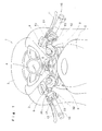
- FIG. 1 is a partially enlarged view of a two-wheeled motorcycle 1 to which a handle switch of one embodiment of the present invention is applied.
- This drawing illustrates a handle and its vicinity as viewed from above and rear of the vehicle body, giving a state which is substantially the same as that as viewed by a rider seated on the motorcycle.
- a steering handle 15 for steering the front wheel (not illustrated) is covered at the vehicle body front side with a cowling 2 as an exterior component.
- a transparent or a semi-transparent windshield screen 3 is attached at the upper central part of the cowling 2, and a meter unit 4 including a speedmeter and a tachometer is disposed below thereof.
- the front wheel of the two-wheeled motorcycle 1 is pivotally supported at the lower ends of a pair of right and left front forks 8 so as to rotate freely.
- An upper part of the front fork 8 is fixed by a top bridge 6 having a key cylinder 7.
- the top bridge 6 is pivotally supported on a vehicle body frame (not illustrated) of the two-wheeled motorcycle 1 so as to move rotationally.
- a pair of right and left handlebars 9 which constitute the steering handle 15 are fixed at the upper ends of the front forks 8. Thereby, the steering handle 15 can be used to steer the front wheel.
- a fuel tank 5 is disposed between the top bridge 6 and a seat (not illustrated).
- a handle grip 10 formed with cylindrical rubber or the like and held by a rider is attached at the ends of the right and left handlebars 9.
- Levers positioned on the vehicle body front side of the handle grip 10 are a front wheel brake lever 11 on the right side and a clutch lever 12 on the left side.
- the handle grip 10 on the right side is supported so as to move rotationally with respect to the handlebar 9 and constituted so as to adjust the output of a power source through rotational operation.
- a handle switch unit Adjacent to the vehicle body center side of the handle grip 10, a handle switch unit provided with switches of various types of electrical components is attached to the right and left handlebars 9.
- An engine stop switch 51, a hazard flasher switch 52 and a starter switch 53 are installed at the handle switch 50 on the right side, whereas a dimmer switch (optical-axis changing switch) 31 for a headlight, a horn switch 32, a turn signal switch 33 are installed at the handle switch 30 on the left side.
- the handle switch of the present invention is applied to the handle switch 30 on the left side having the horn switch 32.
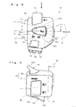
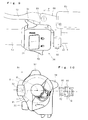
- Fig. 2 is a front elevational view of the handle switch 30.
- the handle switch 30 is attached to the handlebar 9 so that the face indicated by the front elevational view turns to the rider side (the driver side).
- Fig. 3 is a top view as viewed in the direction of A in Fig. 2
- Fig. 4 is a side elevational view as viewed in the direction of B in Fig. 2
- Fig. 5 is a cross sectional view taken along the line E-E in Fig. 3 .
- the same symbols as those described previously indicate the same or similar parts.
- a housing 60 formed with a resin or the like is constituted with a front-side (vehicle body rear side) half body 61 and a back-side (vehicle body front side) half body 62 regarding to the rider (driver) which are divided into two portions in the vehicle body front-back direction across the handlebar 9.
- a seesaw-type dimmer switch 31, a swing pressing-type horn switch 32 and a turn signal switch 33 which is tilted laterally as illustrated are installed at the front-side half body 61. These three switches can be operated only by moving the thumb with the handle grip 10 kept held.
- a passing light switch 34 which can be operated by the index finger, with the handle grip 10 kept held, is installed at the back-side half body 62 of the housing 60.
- the passing light switch 34 is constituted so as to be swung and actuated by pulling forward a projected part 34a extending outward in the vehicle-width direction in such a manner as to catch the projected part with the tip of the finger.
- a drain hole 35 having internally a labyrinth structure is installed at the lower part of the front-side half body 61.
- the three switches to be attached on the front-side half body 61 are constituted so that, with respect to the horn switch 32 positioned approximately at the center in the vertical direction, the other two switches are arranged above and below when the handle switch 30 is viewed from the front. More specifically, the horn switch 32 is disposed at a position which is overlaid on the axis line (D) of the handle grip 10 when projected so as to be viewed from the front and also disposed so as to be positioned on the vehicle body rear side further than the other two switches.
- the horn switch 32 is disposed at a position where a rider effortlessly extends his or her thumb along the direction of the axis line (D) on a state that the rider holds the handle grip 10, thereby improving the operability of the horn switch 32. Further, since there are no other switches in the direction of the axis line (D), it is possible to easily distinguish the horn switch 32 from the other switches.
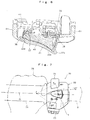
- Fig. 9 is a top view of the handle switch 30, showing arrangement relationships with peripheral components.
- Fig. 10 is a side elevational view of the handle switch 30 including a cross sectional view taken along the line F-F in Fig. 9 .
- a holder 80 for pivotally supporting a clutch lever 12 so as to swing freely is attached in the vicinity of the handle switch 30 which is fixed on the handlebar 9.
- a master cylinder (not illustrated) for a hydraulic clutch in association with the clutch lever 12 is internally installed on the holder 80.
- a reserve tank 83 for clutch fluid is installed at one end of the holder 80.
- a holder half-body 81 is fixed by using a bolt 82, by which a pivot shaft 85 of the clutch lever 12 is attached to the holder 80 clamped to the handlebar 9.
- the pivot shaft 85 is arranged on the vehicle body front side of the handle switch 30 with its axis line directed in the vehicle body vertical direction. Thereby, the clutch lever 12 is pivotally supported so as to swing in the vehicle body front-back direction.
- the horn switch 32 is disposed so as to be overlaid on a line (H) which links an axis line (D) of the handle grip 10 with a center position G of the pivot shaft 85 when the handle switch 30 is viewed as projected from the axis line direction of the handle grip 10.
- the horn switch 32 is disposed in a range where a driver effortlessly extends his or her thumb along the axis line direction of the handle grip on a state that the driver holds the handle grip 10, thus making it possible to provide high operability.
- the horn switch 32 is to be positioned at a position which is overlaid on a swing face formed when the clutch lever 12 swings.
- the horn switch 32 is disposed at a position where the line (H) is substantially in alignment with an approximately central position of the horn switch 32 in the vertical direction, that is, approximately at the center of the housing 60. As shown by the dotted lines (O) and (P), the disposing position is allowed to move vertically within a range at which the horn switch 32 is at least partially overlaid on the line (H). Further, instead of the clutch lever 12, a brake lever may be attached to the holder 80.
- the horn switch 32 is constituted so as to swing about the swing shaft 36 installed at the end closer to the vehicle body outer side.
- the swing shaft 36 is disposed approximately in a perpendicular direction with respect to the axis line (D) when viewed from the front in Fig. 2 . Therefore, the horn switch 32 is swung and actuated by pressing an operating surface 32e closer to the vehicle body inner side, toward the center of the axis line (D), that is, toward the vehicle body front side. According to this constitution, a part closer to the vehicle body center is pressed to actuate the horn switch 32.
- the horn switch 32 is shaped so as to give a longitudinal direction along the direction of the axis line (D).
- a vehicle body inward part (a part at the vehicle body center side) 32c is constituted so as to protrude from the surface of the front-side half body 61 to the rider side.
- This protrusion is set to gradually increase in extent toward vehicle body inward part 32c along the longitudinal direction of the horn switch 32, that is, along the direction of the axis line (D), from vehicle body outward part 32d at which the swing shaft 36 is installed.
- the horn switch 32 is formed so as to be increased in area of the operating surface 32e toward the vehicle body inward part 32c from the vehicle body outward part 32d.
- a contour line of a vehicle body upper part 32a of the horn switch 32 and that of a vehicle body lower part 32b are formed so as to make a pair with an upper part and a lower part across the axis line (D). Then, a clearance between the upper and the lower contour lines is gradually increased from the vehicle body outward part 32d toward the vehicle body inward part 32c, and the horn switch 32 is to be formed approximately in a sector form which is spread out greatly from the swing shaft 36 toward the vehicle body center side.
- a part to be pressed is secured in a sufficient area, by which the horn switch 32 can be easily pressed. Further, the thumb is moved laterally to easily perceive the shape of the switch. Still further, the horn switch 32 is decreased in area of the vehicle body outward part, by which the tip of the thumb is less likely to be caught by the horn switch 32 when the thumb is moved up and down.
- a lower contour line 31a adjacent to the horn switch 32 is formed along an inclined angle of the contour line of the vehicle body upper part 32a of the horn switch 32.
- an upper contour line 33a adjacent to the horn switch 32 is formed with an inclined angle along the contour line of the vehicle body lower part 32b of the horn switch 32.
- the present embodiment deals with a case where two other switches are installed.
- this switch may be disposed on either an upper side or a lower side of the horn switch 32.
- the switches may be arranged in various ways, for example, two switches are disposed on the upper side and one is disposed on the lower side.
- a plate member 43 formed with a metal or the like is arranged between a front-side half body 61 and a back-side half body 62 of the housing 60.
- a projection 44 which is engaged with a positioning hole (not illustrated) provided on handlebar 9 is formed on the plate member 43.
- the projection 44 of the plate member 43 is positioned with respect to the positioning hole on the handlebar 9 so as to make an engagement.
- the handlebar 9 is held between the front-side half body 61 and the back-side half body 62 and connected by using a tapping screw or the like which is inserted into a thread hole 46.
- a through hole 45 is to be approximately equal in diameter to the handlebar 9.
- Fig. 6 is a cross sectional view taken along the line C-C in Fig. 2 . Only the front-side half body 61 is illustrated in this drawing.
- the horn switch 32 will swing by pressing its part closer to the vehicle body inward part 32c, that is, an operating surface 32e closer to the vehicle body center side.
- an inner pressing member 40 at the back of the hom switch 32 is pressed, by which a moving contact 38 moves toward a fixed contact 39.
- the moving contact 38 connected to a wiring 41 is in contact with the fixed contact 39 fixed on the front-side half body 61, thereby actuating a horn.
- An elastic member 37 wound around the swing shaft 36 is fixed on the inner pressing member 40 at one end thereof and also fixed on the front-side half body 61 at the other end thereof.
- the horn switch 32 will return to an initial position illustrated in the drawing due to a resilient force of the elastic member 37, when a rider decreases a force for pressing the operating surface 32e.
- Fig. 7 is a drawing for explaining a positional relationship of the handle switch 30 with the left hand 70 of a rider.
- a vehicle body inward part of the horn switch 32 is disposed at a part closer to the vehicle body center than other switches so that operation can be easily shifted to other switches on a state that the tip of a finger is placed on the horn switch 32.
- Such an arrangement can be realized, for example, by operating surfaces of the dimmer switch 31, the horn switch 32 and the turn signal switch 33 arranged respectively at (K), (L) and (M) points positioned on the same circular arc centering a predetermined position (J) on the handle grip 10.
- the predetermined position (J) is set at a position close to the swinging center of the thumb, by which the operating surfaces of the three switches are to be located on a locus of the tip of the finger formed when the thumb is allowed to swing up and down with the handle grip 10 kept held, thereby each of the switches is further increased in operability.
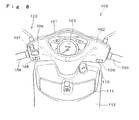
- Fig. 8 is a partially enlarged view of a two-wheeled motorcycle 100 to which a handle switch 120 of a second embodiment of the present invention is applied.
- the two-wheeled motorcycle 100 is a motor scooter-type vehicle having a low-level floor (not illustrated) on which a rider places his or her feet, and a leg shield 112 opposed to the legs of the rider is installed above the low-level floor.
- a lid member 111 for a storage space and an ignition key cylinder 110 are attached to the leg shield 112.
- a handle cover 102 in which a instrument panel 103 is embedded is installed above the leg shield 112.
- the handle cover 102 is an exterior component for covering, from the vehicle body rear side, a steering handle 104 which steers the front wheel, and a front cover 101 which embeds a headlight and a turn signal unit is attached to the vehicle body front side of the handle cover 102 so as to oppose thereto.
- a starter switch 109 is installed on the handle cover 102 in the vicinity of the right handle grip.
- the handle switch 120 of the present embodiment is free of a switch housing separated independently on the right and left sides but constituted to arrange a vertically tilting-type dimmer switch 107, a swinging pressing-type horn switch 106 and a laterally tilting-type turn signal switch 108 in the vicinity of the handle grip on the left side of the handle cover 102 as a switch housing.
- These three switches are similar in arrangement and constitution as with the previously described first embodiment, by which the horn switch 106 is increased in operability and also the handle switch 120 allowing the horn switch 106 to be easily distinguishable is achieved.
- the handle switch of the present invention is applicable to any shape of a switch housing or any type of a vehicle.
- a shape of the switch housing, a shape or structure of the horn switch, structures of other switches and the number thereof shall not be limited to the above-described embodiments but may be modified in various ways.
- the horn switch is included in the handle switch on the left side of the vehicle body.
- the horn switch may be attached to the handle switch on the right side of the vehicle body.
- the handle switch of the present invention shall not be limited to a two-wheeled motorcycle but may be applied to a three-wheeled vehicle, a four-wheeled vehicle or others.
Landscapes
- Engineering & Computer Science (AREA)
- Mechanical Engineering (AREA)
- Rotary Switch, Piano Key Switch, And Lever Switch (AREA)
- Steering Devices For Bicycles And Motorcycles (AREA)
- Mechanical Control Devices (AREA)
- Steering Controls (AREA)
- Push-Button Switches (AREA)
- Mechanisms For Operating Contacts (AREA)
Applications Claiming Priority (2)
| Application Number | Priority Date | Filing Date | Title |
|---|---|---|---|
| JP2008173329A JP5213551B2 (ja) | 2008-07-02 | 2008-07-02 | 車両のハンドルスイッチ |
| PCT/JP2009/002965 WO2010001568A1 (ja) | 2008-07-02 | 2009-06-26 | 車両のハンドルスイッチ |
Publications (3)
| Publication Number | Publication Date |
|---|---|
| EP2292499A1 EP2292499A1 (en) | 2011-03-09 |
| EP2292499A4 EP2292499A4 (en) | 2012-06-06 |
| EP2292499B1 true EP2292499B1 (en) | 2014-10-08 |
Family
ID=41465675
Family Applications (1)
| Application Number | Title | Priority Date | Filing Date |
|---|---|---|---|
| EP09773146.7A Not-in-force EP2292499B1 (en) | 2008-07-02 | 2009-06-26 | Vehicle |
Country Status (9)
| Country | Link |
|---|---|
| US (1) | US8686305B2 (https=) |
| EP (1) | EP2292499B1 (https=) |
| JP (1) | JP5213551B2 (https=) |
| CN (1) | CN102105346B (https=) |
| AR (1) | AR072372A1 (https=) |
| BR (1) | BRPI0913645B8 (https=) |
| ES (1) | ES2516016T3 (https=) |
| MX (1) | MX2010014143A (https=) |
| WO (1) | WO2010001568A1 (https=) |
Families Citing this family (17)
| Publication number | Priority date | Publication date | Assignee | Title |
|---|---|---|---|---|
| EP2657121B1 (en) * | 2012-04-23 | 2015-02-18 | Campagnolo S.r.l. | Bar-end electric actuation device of a bicycle gearshift |
| USD729710S1 (en) * | 2013-06-03 | 2015-05-19 | Toyo Denso Kabushiki Kaisha | Handle switch |
| CN103489732B (zh) * | 2013-09-16 | 2015-05-27 | 温州盛世机车业有限公司 | 迷你型组合开关 |
| JP6214351B2 (ja) * | 2013-11-18 | 2017-10-18 | 朝日電装株式会社 | ハンドルバー用スイッチ装置 |
| JP6194271B2 (ja) * | 2014-03-28 | 2017-09-06 | 本田技研工業株式会社 | 車両用ハンドルスイッチ |
| JP1518184S (https=) * | 2014-08-29 | 2015-02-23 | ||
| JP1518185S (https=) * | 2014-08-29 | 2015-02-23 | ||
| JP2016192252A (ja) * | 2015-03-30 | 2016-11-10 | 本田技研工業株式会社 | 車両用のハンドルスイッチ |
| US9499230B1 (en) * | 2015-05-27 | 2016-11-22 | Sensata Technologies, Inc. | Fixation adapter for handlebar |
| USD841160S1 (en) | 2016-04-01 | 2019-02-19 | Deka Products Limited Partnership | Endoscope |
| JP1585660S (https=) * | 2017-03-24 | 2018-01-09 | ||
| USD856855S1 (en) * | 2018-02-08 | 2019-08-20 | Matthew J Steele | Handlebar switch |
| CN113748078B (zh) * | 2019-04-04 | 2023-08-08 | 捷尔杰产业公司 | 用于紧凑型车辆的控制站 |
| USD913166S1 (en) * | 2019-11-04 | 2021-03-16 | Ktm Ag | Motor vehicle switch |
| USD915950S1 (en) * | 2019-11-04 | 2021-04-13 | Ktm Ag | Motor vehicle switch |
| WO2022074742A1 (ja) * | 2020-10-06 | 2022-04-14 | ヤマハ発動機株式会社 | 鞍乗型車両 |
| US12060130B1 (en) * | 2020-12-28 | 2024-08-13 | Keith Edward Conger | Device and software that provides handlebar control and motorcycle performance data wirelessly to a portable computing device |
Family Cites Families (12)
| Publication number | Priority date | Publication date | Assignee | Title |
|---|---|---|---|---|
| JPH07397Y2 (ja) * | 1987-01-14 | 1995-01-11 | 本田技研工業株式会社 | 自動二輪車等のスイッチ装置 |
| JP3662659B2 (ja) | 1996-02-23 | 2005-06-22 | 朝日電装株式会社 | 圧着摺動スイッチ |
| JP2000016366A (ja) * | 1998-06-29 | 2000-01-18 | Asahi Denso Co Ltd | チョーク操作装置付ハンドルスイッチ |
| JP2001247070A (ja) * | 2000-03-03 | 2001-09-11 | Honda Motor Co Ltd | 鞍乗り型車両のスイッチパネル装置 |
| US6538221B1 (en) * | 2000-09-14 | 2003-03-25 | Shimano Inc. | Key guard for a function key on a bicycle control panel |
| US6695090B2 (en) * | 2001-02-15 | 2004-02-24 | Motorcycle Riders Holdings Corp. | Back-lit handlebar control assembly |
| JP3663366B2 (ja) * | 2001-04-26 | 2005-06-22 | 朝日電装株式会社 | プッシュスイッチ |
| JP4580129B2 (ja) | 2001-09-04 | 2010-11-10 | 本田技研工業株式会社 | 車両のウインカ構造 |
| JP2003312564A (ja) * | 2002-04-19 | 2003-11-06 | Yamaha Motor Co Ltd | 自動二輪車のハンドルスイッチ取付構造 |
| JP4166586B2 (ja) * | 2003-01-23 | 2008-10-15 | 朝日電装株式会社 | ハンドルスイッチ |
| JP2005053452A (ja) * | 2003-07-31 | 2005-03-03 | Daytona:Kk | ハンドルスイッチ |
| JP4890074B2 (ja) | 2006-04-03 | 2012-03-07 | 東洋電装株式会社 | 車両のハンドルスイッチ装置 |
-
2008
- 2008-07-02 JP JP2008173329A patent/JP5213551B2/ja not_active Expired - Fee Related
-
2009
- 2009-06-26 US US13/001,572 patent/US8686305B2/en not_active Expired - Fee Related
- 2009-06-26 MX MX2010014143A patent/MX2010014143A/es active IP Right Grant
- 2009-06-26 WO PCT/JP2009/002965 patent/WO2010001568A1/ja not_active Ceased
- 2009-06-26 ES ES09773146.7T patent/ES2516016T3/es active Active
- 2009-06-26 EP EP09773146.7A patent/EP2292499B1/en not_active Not-in-force
- 2009-06-26 AR ARP090102374A patent/AR072372A1/es active IP Right Grant
- 2009-06-26 BR BRPI0913645A patent/BRPI0913645B8/pt active IP Right Grant
- 2009-06-26 CN CN200980125023.2A patent/CN102105346B/zh active Active
Also Published As
| Publication number | Publication date |
|---|---|
| CN102105346B (zh) | 2014-12-17 |
| ES2516016T3 (es) | 2014-10-30 |
| AR072372A1 (es) | 2010-08-25 |
| EP2292499A4 (en) | 2012-06-06 |
| US8686305B2 (en) | 2014-04-01 |
| WO2010001568A1 (ja) | 2010-01-07 |
| BRPI0913645A2 (pt) | 2015-10-13 |
| MX2010014143A (es) | 2011-03-04 |
| BRPI0913645B8 (pt) | 2022-05-31 |
| EP2292499A1 (en) | 2011-03-09 |
| JP2010012862A (ja) | 2010-01-21 |
| JP5213551B2 (ja) | 2013-06-19 |
| US20110108397A1 (en) | 2011-05-12 |
| CN102105346A (zh) | 2011-06-22 |
| BRPI0913645B1 (pt) | 2019-05-14 |
Similar Documents
| Publication | Publication Date | Title |
|---|---|---|
| EP2292499B1 (en) | Vehicle | |
| JP5403804B2 (ja) | ハンドルスイッチ | |
| JP5131103B2 (ja) | 自動二輪車のハンドルスイッチ | |
| US20150274246A1 (en) | Vehicle handle switch and vehicle incorporating same | |
| US9941079B2 (en) | Handle switch for vehicle | |
| JP2020179753A (ja) | ハンドルスイッチ | |
| JP6300743B2 (ja) | 鞍乗り型車両におけるスクリーン可動装置 | |
| JP2009056872A (ja) | ハンドル用変速スイッチ | |
| US9018551B2 (en) | Handlebar switch for motorcycle | |
| EP1323955A1 (en) | An ergonomic manual switch arrangement for motorcycles | |
| JP4729509B2 (ja) | 車両運転席の衝撃吸収構造 | |
| JP5015614B2 (ja) | 車両走行系コンビネーションスイッチ装置 | |
| JP2014061853A (ja) | 鞍乗型車両の前部構造 | |
| JP5124855B2 (ja) | 自動二輪車用ハンドルスイッチ装置 | |
| JP2023131553A (ja) | 車両 | |
| JP4887087B2 (ja) | 変速シフト用ハンドルスイッチ | |
| JP2016159719A (ja) | 鞍乗り型車両におけるスクリーン可動装置 | |
| JP2009101902A (ja) | ハンドルバー用スイッチ装置 | |
| JP4453963B2 (ja) | 車両用スイッチ構造 | |
| JP2025168915A (ja) | シフト装置 | |
| JP2016159718A (ja) | 鞍乗り型車両におけるスクリーン可動装置 | |
| JP3595919B2 (ja) | キーインタロックケーブルの配索構造 | |
| WO2022074742A1 (ja) | 鞍乗型車両 |
Legal Events
| Date | Code | Title | Description |
|---|---|---|---|
| PUAI | Public reference made under article 153(3) epc to a published international application that has entered the european phase |
Free format text: ORIGINAL CODE: 0009012 |
|
| 17P | Request for examination filed |
Effective date: 20101214 |
|
| AK | Designated contracting states |
Kind code of ref document: A1 Designated state(s): AT BE BG CH CY CZ DE DK EE ES FI FR GB GR HR HU IE IS IT LI LT LU LV MC MK MT NL NO PL PT RO SE SI SK TR |
|
| AX | Request for extension of the european patent |
Extension state: AL BA RS |
|
| DAX | Request for extension of the european patent (deleted) | ||
| REG | Reference to a national code |
Ref country code: DE Ref legal event code: R079 Ref document number: 602009027100 Country of ref document: DE Free format text: PREVIOUS MAIN CLASS: B62J0006160000 Ipc: B62K0011140000 |
|
| A4 | Supplementary search report drawn up and despatched |
Effective date: 20120507 |
|
| RIC1 | Information provided on ipc code assigned before grant |
Ipc: B62K 23/02 20060101ALI20120427BHEP Ipc: B62K 11/14 20060101AFI20120427BHEP |
|
| 17Q | First examination report despatched |
Effective date: 20131004 |
|
| GRAP | Despatch of communication of intention to grant a patent |
Free format text: ORIGINAL CODE: EPIDOSNIGR1 |
|
| INTG | Intention to grant announced |
Effective date: 20140424 |
|
| GRAS | Grant fee paid |
Free format text: ORIGINAL CODE: EPIDOSNIGR3 |
|
| GRAA | (expected) grant |
Free format text: ORIGINAL CODE: 0009210 |
|
| AK | Designated contracting states |
Kind code of ref document: B1 Designated state(s): AT BE BG CH CY CZ DE DK EE ES FI FR GB GR HR HU IE IS IT LI LT LU LV MC MK MT NL NO PL PT RO SE SI SK TR |
|
| REG | Reference to a national code |
Ref country code: GB Ref legal event code: FG4D |
|
| REG | Reference to a national code |
Ref country code: AT Ref legal event code: REF Ref document number: 690423 Country of ref document: AT Kind code of ref document: T Effective date: 20141015 Ref country code: CH Ref legal event code: EP |
|
| REG | Reference to a national code |
Ref country code: ES Ref legal event code: FG2A Ref document number: 2516016 Country of ref document: ES Kind code of ref document: T3 Effective date: 20141030 |
|
| REG | Reference to a national code |
Ref country code: IE Ref legal event code: FG4D |
|
| REG | Reference to a national code |
Ref country code: DE Ref legal event code: R096 Ref document number: 602009027100 Country of ref document: DE Effective date: 20141120 |
|
| REG | Reference to a national code |
Ref country code: NL Ref legal event code: VDEP Effective date: 20141008 |
|
| REG | Reference to a national code |
Ref country code: AT Ref legal event code: MK05 Ref document number: 690423 Country of ref document: AT Kind code of ref document: T Effective date: 20141008 |
|
| REG | Reference to a national code |
Ref country code: LT Ref legal event code: MG4D |
|
| PG25 | Lapsed in a contracting state [announced via postgrant information from national office to epo] |
Ref country code: NL Free format text: LAPSE BECAUSE OF FAILURE TO SUBMIT A TRANSLATION OF THE DESCRIPTION OR TO PAY THE FEE WITHIN THE PRESCRIBED TIME-LIMIT Effective date: 20141008 |
|
| PG25 | Lapsed in a contracting state [announced via postgrant information from national office to epo] |
Ref country code: FI Free format text: LAPSE BECAUSE OF FAILURE TO SUBMIT A TRANSLATION OF THE DESCRIPTION OR TO PAY THE FEE WITHIN THE PRESCRIBED TIME-LIMIT Effective date: 20141008 Ref country code: NO Free format text: LAPSE BECAUSE OF FAILURE TO SUBMIT A TRANSLATION OF THE DESCRIPTION OR TO PAY THE FEE WITHIN THE PRESCRIBED TIME-LIMIT Effective date: 20150108 Ref country code: LT Free format text: LAPSE BECAUSE OF FAILURE TO SUBMIT A TRANSLATION OF THE DESCRIPTION OR TO PAY THE FEE WITHIN THE PRESCRIBED TIME-LIMIT Effective date: 20141008 Ref country code: PT Free format text: LAPSE BECAUSE OF FAILURE TO SUBMIT A TRANSLATION OF THE DESCRIPTION OR TO PAY THE FEE WITHIN THE PRESCRIBED TIME-LIMIT Effective date: 20150209 Ref country code: IS Free format text: LAPSE BECAUSE OF FAILURE TO SUBMIT A TRANSLATION OF THE DESCRIPTION OR TO PAY THE FEE WITHIN THE PRESCRIBED TIME-LIMIT Effective date: 20150208 |
|
| PG25 | Lapsed in a contracting state [announced via postgrant information from national office to epo] |
Ref country code: AT Free format text: LAPSE BECAUSE OF FAILURE TO SUBMIT A TRANSLATION OF THE DESCRIPTION OR TO PAY THE FEE WITHIN THE PRESCRIBED TIME-LIMIT Effective date: 20141008 Ref country code: CY Free format text: LAPSE BECAUSE OF FAILURE TO SUBMIT A TRANSLATION OF THE DESCRIPTION OR TO PAY THE FEE WITHIN THE PRESCRIBED TIME-LIMIT Effective date: 20141008 Ref country code: PL Free format text: LAPSE BECAUSE OF FAILURE TO SUBMIT A TRANSLATION OF THE DESCRIPTION OR TO PAY THE FEE WITHIN THE PRESCRIBED TIME-LIMIT Effective date: 20141008 Ref country code: SE Free format text: LAPSE BECAUSE OF FAILURE TO SUBMIT A TRANSLATION OF THE DESCRIPTION OR TO PAY THE FEE WITHIN THE PRESCRIBED TIME-LIMIT Effective date: 20141008 Ref country code: HR Free format text: LAPSE BECAUSE OF FAILURE TO SUBMIT A TRANSLATION OF THE DESCRIPTION OR TO PAY THE FEE WITHIN THE PRESCRIBED TIME-LIMIT Effective date: 20141008 Ref country code: GR Free format text: LAPSE BECAUSE OF FAILURE TO SUBMIT A TRANSLATION OF THE DESCRIPTION OR TO PAY THE FEE WITHIN THE PRESCRIBED TIME-LIMIT Effective date: 20150109 Ref country code: LV Free format text: LAPSE BECAUSE OF FAILURE TO SUBMIT A TRANSLATION OF THE DESCRIPTION OR TO PAY THE FEE WITHIN THE PRESCRIBED TIME-LIMIT Effective date: 20141008 |
|
| REG | Reference to a national code |
Ref country code: DE Ref legal event code: R097 Ref document number: 602009027100 Country of ref document: DE |
|
| PG25 | Lapsed in a contracting state [announced via postgrant information from national office to epo] |
Ref country code: EE Free format text: LAPSE BECAUSE OF FAILURE TO SUBMIT A TRANSLATION OF THE DESCRIPTION OR TO PAY THE FEE WITHIN THE PRESCRIBED TIME-LIMIT Effective date: 20141008 Ref country code: DK Free format text: LAPSE BECAUSE OF FAILURE TO SUBMIT A TRANSLATION OF THE DESCRIPTION OR TO PAY THE FEE WITHIN THE PRESCRIBED TIME-LIMIT Effective date: 20141008 Ref country code: CZ Free format text: LAPSE BECAUSE OF FAILURE TO SUBMIT A TRANSLATION OF THE DESCRIPTION OR TO PAY THE FEE WITHIN THE PRESCRIBED TIME-LIMIT Effective date: 20141008 Ref country code: SK Free format text: LAPSE BECAUSE OF FAILURE TO SUBMIT A TRANSLATION OF THE DESCRIPTION OR TO PAY THE FEE WITHIN THE PRESCRIBED TIME-LIMIT Effective date: 20141008 Ref country code: RO Free format text: LAPSE BECAUSE OF FAILURE TO SUBMIT A TRANSLATION OF THE DESCRIPTION OR TO PAY THE FEE WITHIN THE PRESCRIBED TIME-LIMIT Effective date: 20141008 |
|
| PLBE | No opposition filed within time limit |
Free format text: ORIGINAL CODE: 0009261 |
|
| STAA | Information on the status of an ep patent application or granted ep patent |
Free format text: STATUS: NO OPPOSITION FILED WITHIN TIME LIMIT |
|
| 26N | No opposition filed |
Effective date: 20150709 |
|
| PG25 | Lapsed in a contracting state [announced via postgrant information from national office to epo] |
Ref country code: MC Free format text: LAPSE BECAUSE OF FAILURE TO SUBMIT A TRANSLATION OF THE DESCRIPTION OR TO PAY THE FEE WITHIN THE PRESCRIBED TIME-LIMIT Effective date: 20141008 |
|
| REG | Reference to a national code |
Ref country code: CH Ref legal event code: PL |
|
| GBPC | Gb: european patent ceased through non-payment of renewal fee |
Effective date: 20150626 |
|
| PG25 | Lapsed in a contracting state [announced via postgrant information from national office to epo] |
Ref country code: LU Free format text: LAPSE BECAUSE OF FAILURE TO SUBMIT A TRANSLATION OF THE DESCRIPTION OR TO PAY THE FEE WITHIN THE PRESCRIBED TIME-LIMIT Effective date: 20150626 Ref country code: SI Free format text: LAPSE BECAUSE OF FAILURE TO SUBMIT A TRANSLATION OF THE DESCRIPTION OR TO PAY THE FEE WITHIN THE PRESCRIBED TIME-LIMIT Effective date: 20141008 |
|
| REG | Reference to a national code |
Ref country code: IE Ref legal event code: MM4A |
|
| PG25 | Lapsed in a contracting state [announced via postgrant information from national office to epo] |
Ref country code: GB Free format text: LAPSE BECAUSE OF NON-PAYMENT OF DUE FEES Effective date: 20150626 Ref country code: CH Free format text: LAPSE BECAUSE OF NON-PAYMENT OF DUE FEES Effective date: 20150630 Ref country code: LI Free format text: LAPSE BECAUSE OF NON-PAYMENT OF DUE FEES Effective date: 20150630 Ref country code: IE Free format text: LAPSE BECAUSE OF NON-PAYMENT OF DUE FEES Effective date: 20150626 |
|
| REG | Reference to a national code |
Ref country code: FR Ref legal event code: PLFP Year of fee payment: 8 |
|
| PG25 | Lapsed in a contracting state [announced via postgrant information from national office to epo] |
Ref country code: MT Free format text: LAPSE BECAUSE OF FAILURE TO SUBMIT A TRANSLATION OF THE DESCRIPTION OR TO PAY THE FEE WITHIN THE PRESCRIBED TIME-LIMIT Effective date: 20141008 |
|
| REG | Reference to a national code |
Ref country code: FR Ref legal event code: PLFP Year of fee payment: 9 |
|
| PG25 | Lapsed in a contracting state [announced via postgrant information from national office to epo] |
Ref country code: BG Free format text: LAPSE BECAUSE OF FAILURE TO SUBMIT A TRANSLATION OF THE DESCRIPTION OR TO PAY THE FEE WITHIN THE PRESCRIBED TIME-LIMIT Effective date: 20141008 Ref country code: HU Free format text: LAPSE BECAUSE OF FAILURE TO SUBMIT A TRANSLATION OF THE DESCRIPTION OR TO PAY THE FEE WITHIN THE PRESCRIBED TIME-LIMIT; INVALID AB INITIO Effective date: 20090626 |
|
| REG | Reference to a national code |
Ref country code: DE Ref legal event code: R084 Ref document number: 602009027100 Country of ref document: DE |
|
| PG25 | Lapsed in a contracting state [announced via postgrant information from national office to epo] |
Ref country code: TR Free format text: LAPSE BECAUSE OF FAILURE TO SUBMIT A TRANSLATION OF THE DESCRIPTION OR TO PAY THE FEE WITHIN THE PRESCRIBED TIME-LIMIT Effective date: 20141008 |
|
| PG25 | Lapsed in a contracting state [announced via postgrant information from national office to epo] |
Ref country code: BE Free format text: LAPSE BECAUSE OF FAILURE TO SUBMIT A TRANSLATION OF THE DESCRIPTION OR TO PAY THE FEE WITHIN THE PRESCRIBED TIME-LIMIT Effective date: 20141008 |
|
| REG | Reference to a national code |
Ref country code: FR Ref legal event code: PLFP Year of fee payment: 10 |
|
| PG25 | Lapsed in a contracting state [announced via postgrant information from national office to epo] |
Ref country code: MK Free format text: LAPSE BECAUSE OF FAILURE TO SUBMIT A TRANSLATION OF THE DESCRIPTION OR TO PAY THE FEE WITHIN THE PRESCRIBED TIME-LIMIT Effective date: 20141008 |
|
| PGFP | Annual fee paid to national office [announced via postgrant information from national office to epo] |
Ref country code: FR Payment date: 20180511 Year of fee payment: 10 |
|
| PGFP | Annual fee paid to national office [announced via postgrant information from national office to epo] |
Ref country code: ES Payment date: 20180723 Year of fee payment: 10 |
|
| PGFP | Annual fee paid to national office [announced via postgrant information from national office to epo] |
Ref country code: IT Payment date: 20190620 Year of fee payment: 11 Ref country code: DE Payment date: 20190612 Year of fee payment: 11 |
|
| PG25 | Lapsed in a contracting state [announced via postgrant information from national office to epo] |
Ref country code: FR Free format text: LAPSE BECAUSE OF NON-PAYMENT OF DUE FEES Effective date: 20190630 |
|
| REG | Reference to a national code |
Ref country code: ES Ref legal event code: FD2A Effective date: 20201030 |
|
| REG | Reference to a national code |
Ref country code: DE Ref legal event code: R119 Ref document number: 602009027100 Country of ref document: DE |
|
| PG25 | Lapsed in a contracting state [announced via postgrant information from national office to epo] |
Ref country code: ES Free format text: LAPSE BECAUSE OF NON-PAYMENT OF DUE FEES Effective date: 20190627 |
|
| PG25 | Lapsed in a contracting state [announced via postgrant information from national office to epo] |
Ref country code: DE Free format text: LAPSE BECAUSE OF NON-PAYMENT OF DUE FEES Effective date: 20210101 |
|
| PG25 | Lapsed in a contracting state [announced via postgrant information from national office to epo] |
Ref country code: IT Free format text: LAPSE BECAUSE OF NON-PAYMENT OF DUE FEES Effective date: 20200626 |