EP2292427B1 - Feuille intercalaire pour vitrage feuilleté - Google Patents
Feuille intercalaire pour vitrage feuilleté Download PDFInfo
- Publication number
- EP2292427B1 EP2292427B1 EP20100180354 EP10180354A EP2292427B1 EP 2292427 B1 EP2292427 B1 EP 2292427B1 EP 20100180354 EP20100180354 EP 20100180354 EP 10180354 A EP10180354 A EP 10180354A EP 2292427 B1 EP2292427 B1 EP 2292427B1
- Authority
- EP
- European Patent Office
- Prior art keywords
- interlayer
- laminated glass
- embossment
- concave
- deaeration
- Prior art date
- Legal status (The legal status is an assumption and is not a legal conclusion. Google has not performed a legal analysis and makes no representation as to the accuracy of the status listed.)
- Expired - Lifetime
Links
Images


Classifications
-
- C—CHEMISTRY; METALLURGY
- C03—GLASS; MINERAL OR SLAG WOOL
- C03C—CHEMICAL COMPOSITION OF GLASSES, GLAZES OR VITREOUS ENAMELS; SURFACE TREATMENT OF GLASS; SURFACE TREATMENT OF FIBRES OR FILAMENTS MADE FROM GLASS, MINERALS OR SLAGS; JOINING GLASS TO GLASS OR OTHER MATERIALS
- C03C27/00—Joining pieces of glass to pieces of other inorganic material; Joining glass to glass other than by fusing
- C03C27/06—Joining glass to glass by processes other than fusing
- C03C27/10—Joining glass to glass by processes other than fusing with the aid of adhesive specially adapted for that purpose
-
- B—PERFORMING OPERATIONS; TRANSPORTING
- B32—LAYERED PRODUCTS
- B32B—LAYERED PRODUCTS, i.e. PRODUCTS BUILT-UP OF STRATA OF FLAT OR NON-FLAT, e.g. CELLULAR OR HONEYCOMB, FORM
- B32B17/00—Layered products essentially comprising sheet glass, or glass, slag, or like fibres
- B32B17/06—Layered products essentially comprising sheet glass, or glass, slag, or like fibres comprising glass as the main or only constituent of a layer, next to another layer of a specific material
- B32B17/10—Layered products essentially comprising sheet glass, or glass, slag, or like fibres comprising glass as the main or only constituent of a layer, next to another layer of a specific material of synthetic resin
- B32B17/10005—Layered products essentially comprising sheet glass, or glass, slag, or like fibres comprising glass as the main or only constituent of a layer, next to another layer of a specific material of synthetic resin laminated safety glass or glazing
- B32B17/1055—Layered products essentially comprising sheet glass, or glass, slag, or like fibres comprising glass as the main or only constituent of a layer, next to another layer of a specific material of synthetic resin laminated safety glass or glazing characterized by the resin layer, i.e. interlayer
- B32B17/10761—Layered products essentially comprising sheet glass, or glass, slag, or like fibres comprising glass as the main or only constituent of a layer, next to another layer of a specific material of synthetic resin laminated safety glass or glazing characterized by the resin layer, i.e. interlayer containing vinyl acetal
-
- B—PERFORMING OPERATIONS; TRANSPORTING
- B29—WORKING OF PLASTICS; WORKING OF SUBSTANCES IN A PLASTIC STATE IN GENERAL
- B29C—SHAPING OR JOINING OF PLASTICS; SHAPING OF MATERIAL IN A PLASTIC STATE, NOT OTHERWISE PROVIDED FOR; AFTER-TREATMENT OF THE SHAPED PRODUCTS, e.g. REPAIRING
- B29C59/00—Surface shaping of articles, e.g. embossing; Apparatus therefor
- B29C59/02—Surface shaping of articles, e.g. embossing; Apparatus therefor by mechanical means, e.g. pressing
- B29C59/022—Surface shaping of articles, e.g. embossing; Apparatus therefor by mechanical means, e.g. pressing characterised by the disposition or the configuration, e.g. dimensions, of the embossments or the shaping tools therefor
-
- B—PERFORMING OPERATIONS; TRANSPORTING
- B32—LAYERED PRODUCTS
- B32B—LAYERED PRODUCTS, i.e. PRODUCTS BUILT-UP OF STRATA OF FLAT OR NON-FLAT, e.g. CELLULAR OR HONEYCOMB, FORM
- B32B17/00—Layered products essentially comprising sheet glass, or glass, slag, or like fibres
- B32B17/06—Layered products essentially comprising sheet glass, or glass, slag, or like fibres comprising glass as the main or only constituent of a layer, next to another layer of a specific material
- B32B17/10—Layered products essentially comprising sheet glass, or glass, slag, or like fibres comprising glass as the main or only constituent of a layer, next to another layer of a specific material of synthetic resin
- B32B17/10005—Layered products essentially comprising sheet glass, or glass, slag, or like fibres comprising glass as the main or only constituent of a layer, next to another layer of a specific material of synthetic resin laminated safety glass or glazing
- B32B17/1055—Layered products essentially comprising sheet glass, or glass, slag, or like fibres comprising glass as the main or only constituent of a layer, next to another layer of a specific material of synthetic resin laminated safety glass or glazing characterized by the resin layer, i.e. interlayer
- B32B17/10559—Shape of the cross-section
- B32B17/10577—Surface roughness
- B32B17/10587—Surface roughness created by embossing
-
- B—PERFORMING OPERATIONS; TRANSPORTING
- B29—WORKING OF PLASTICS; WORKING OF SUBSTANCES IN A PLASTIC STATE IN GENERAL
- B29C—SHAPING OR JOINING OF PLASTICS; SHAPING OF MATERIAL IN A PLASTIC STATE, NOT OTHERWISE PROVIDED FOR; AFTER-TREATMENT OF THE SHAPED PRODUCTS, e.g. REPAIRING
- B29C59/00—Surface shaping of articles, e.g. embossing; Apparatus therefor
- B29C59/02—Surface shaping of articles, e.g. embossing; Apparatus therefor by mechanical means, e.g. pressing
- B29C59/022—Surface shaping of articles, e.g. embossing; Apparatus therefor by mechanical means, e.g. pressing characterised by the disposition or the configuration, e.g. dimensions, of the embossments or the shaping tools therefor
- B29C2059/023—Microembossing
-
- B—PERFORMING OPERATIONS; TRANSPORTING
- B29—WORKING OF PLASTICS; WORKING OF SUBSTANCES IN A PLASTIC STATE IN GENERAL
- B29C—SHAPING OR JOINING OF PLASTICS; SHAPING OF MATERIAL IN A PLASTIC STATE, NOT OTHERWISE PROVIDED FOR; AFTER-TREATMENT OF THE SHAPED PRODUCTS, e.g. REPAIRING
- B29C59/00—Surface shaping of articles, e.g. embossing; Apparatus therefor
- B29C59/02—Surface shaping of articles, e.g. embossing; Apparatus therefor by mechanical means, e.g. pressing
- B29C59/04—Surface shaping of articles, e.g. embossing; Apparatus therefor by mechanical means, e.g. pressing using rollers or endless belts
-
- B—PERFORMING OPERATIONS; TRANSPORTING
- B29—WORKING OF PLASTICS; WORKING OF SUBSTANCES IN A PLASTIC STATE IN GENERAL
- B29K—INDEXING SCHEME ASSOCIATED WITH SUBCLASSES B29B, B29C OR B29D, RELATING TO MOULDING MATERIALS OR TO MATERIALS FOR MOULDS, REINFORCEMENTS, FILLERS OR PREFORMED PARTS, e.g. INSERTS
- B29K2029/00—Use of polyvinylalcohols, polyvinylethers, polyvinylaldehydes, polyvinylketones or polyvinylketals or derivatives thereof as moulding material
- B29K2029/14—Polyvinylacetals
-
- Y—GENERAL TAGGING OF NEW TECHNOLOGICAL DEVELOPMENTS; GENERAL TAGGING OF CROSS-SECTIONAL TECHNOLOGIES SPANNING OVER SEVERAL SECTIONS OF THE IPC; TECHNICAL SUBJECTS COVERED BY FORMER USPC CROSS-REFERENCE ART COLLECTIONS [XRACs] AND DIGESTS
- Y10—TECHNICAL SUBJECTS COVERED BY FORMER USPC
- Y10T—TECHNICAL SUBJECTS COVERED BY FORMER US CLASSIFICATION
- Y10T428/00—Stock material or miscellaneous articles
- Y10T428/24—Structurally defined web or sheet [e.g., overall dimension, etc.]
- Y10T428/24355—Continuous and nonuniform or irregular surface on layer or component [e.g., roofing, etc.]
-
- Y—GENERAL TAGGING OF NEW TECHNOLOGICAL DEVELOPMENTS; GENERAL TAGGING OF CROSS-SECTIONAL TECHNOLOGIES SPANNING OVER SEVERAL SECTIONS OF THE IPC; TECHNICAL SUBJECTS COVERED BY FORMER USPC CROSS-REFERENCE ART COLLECTIONS [XRACs] AND DIGESTS
- Y10—TECHNICAL SUBJECTS COVERED BY FORMER USPC
- Y10T—TECHNICAL SUBJECTS COVERED BY FORMER US CLASSIFICATION
- Y10T428/00—Stock material or miscellaneous articles
- Y10T428/24—Structurally defined web or sheet [e.g., overall dimension, etc.]
- Y10T428/24479—Structurally defined web or sheet [e.g., overall dimension, etc.] including variation in thickness
- Y10T428/2457—Parallel ribs and/or grooves
-
- Y—GENERAL TAGGING OF NEW TECHNOLOGICAL DEVELOPMENTS; GENERAL TAGGING OF CROSS-SECTIONAL TECHNOLOGIES SPANNING OVER SEVERAL SECTIONS OF THE IPC; TECHNICAL SUBJECTS COVERED BY FORMER USPC CROSS-REFERENCE ART COLLECTIONS [XRACs] AND DIGESTS
- Y10—TECHNICAL SUBJECTS COVERED BY FORMER USPC
- Y10T—TECHNICAL SUBJECTS COVERED BY FORMER US CLASSIFICATION
- Y10T428/00—Stock material or miscellaneous articles
- Y10T428/24—Structurally defined web or sheet [e.g., overall dimension, etc.]
- Y10T428/24479—Structurally defined web or sheet [e.g., overall dimension, etc.] including variation in thickness
- Y10T428/24612—Composite web or sheet
-
- Y—GENERAL TAGGING OF NEW TECHNOLOGICAL DEVELOPMENTS; GENERAL TAGGING OF CROSS-SECTIONAL TECHNOLOGIES SPANNING OVER SEVERAL SECTIONS OF THE IPC; TECHNICAL SUBJECTS COVERED BY FORMER USPC CROSS-REFERENCE ART COLLECTIONS [XRACs] AND DIGESTS
- Y10—TECHNICAL SUBJECTS COVERED BY FORMER USPC
- Y10T—TECHNICAL SUBJECTS COVERED BY FORMER US CLASSIFICATION
- Y10T428/00—Stock material or miscellaneous articles
- Y10T428/24—Structurally defined web or sheet [e.g., overall dimension, etc.]
- Y10T428/24628—Nonplanar uniform thickness material
-
- Y—GENERAL TAGGING OF NEW TECHNOLOGICAL DEVELOPMENTS; GENERAL TAGGING OF CROSS-SECTIONAL TECHNOLOGIES SPANNING OVER SEVERAL SECTIONS OF THE IPC; TECHNICAL SUBJECTS COVERED BY FORMER USPC CROSS-REFERENCE ART COLLECTIONS [XRACs] AND DIGESTS
- Y10—TECHNICAL SUBJECTS COVERED BY FORMER USPC
- Y10T—TECHNICAL SUBJECTS COVERED BY FORMER US CLASSIFICATION
- Y10T428/00—Stock material or miscellaneous articles
- Y10T428/31504—Composite [nonstructural laminate]
- Y10T428/31511—Of epoxy ether
- Y10T428/31515—As intermediate layer
- Y10T428/31518—Next to glass or quartz
-
- Y—GENERAL TAGGING OF NEW TECHNOLOGICAL DEVELOPMENTS; GENERAL TAGGING OF CROSS-SECTIONAL TECHNOLOGIES SPANNING OVER SEVERAL SECTIONS OF THE IPC; TECHNICAL SUBJECTS COVERED BY FORMER USPC CROSS-REFERENCE ART COLLECTIONS [XRACs] AND DIGESTS
- Y10—TECHNICAL SUBJECTS COVERED BY FORMER USPC
- Y10T—TECHNICAL SUBJECTS COVERED BY FORMER US CLASSIFICATION
- Y10T428/00—Stock material or miscellaneous articles
- Y10T428/31504—Composite [nonstructural laminate]
- Y10T428/31551—Of polyamidoester [polyurethane, polyisocyanate, polycarbamate, etc.]
- Y10T428/31627—Next to aldehyde or ketone condensation product
- Y10T428/3163—Next to acetal of polymerized unsaturated alcohol [e.g., formal butyral, etc.]
Definitions
- the present invention relates to an interlayer for a laminated glass providing for improved deaeration and a laminated glass comprising the same.
- the laminated glass manufactured by interposing an interlayer comprising a sheet made of a thermoplastic resin such as plasticized polyvinyl butyral between glass sheets and bonding them together into an integral unit is in broad use for glazing the windows of automobiles, aircraft, and buildings.
- the glass When such a laminated glass is subjected to an external impact, the glass may break up but the interlayer sandwiched between the component glass sheets will not readily be destroyed and even after breakage, the glass remains glued to the interlayer so that its fragments will not be scattered. Therefore, the bodies of men in the vehicle or building are protected against the injury by fragments of the broken glass.
- Such a laminated glass is usually manufactured by interposing an interlayer between glass sheets, drawing the whole over a nip roll or placing it in a rubber bag and evacuating the bag to effect preliminary contact bonding with concurrent removal of the residual air entrapped between the glass and the interlayer under suction, and finally carrying out final contact bonding at elevated temperature and pressure in an autoclave.
- the interlayer mentioned above is required to satisfy not only the basic performance requirements such as good clarity, bondability, bullet resistance, weather resistance, etc. but also the requirement that it does not undergo blocking during storage, the requirement that it provides for good workability in the insertion thereof between glass sheets, and the requirement that it lends itself to efficient deaeration in preliminary contact bonding so that the formation of bubbles by entrapment of air may be precluded.
- thermoplastic resin interlayer comprising a flexible thermoplastic resin film or sheet having a fine concavo-convex (embossed) surface pattern for use as an interlayer for lamination characterized in that at least one side of which is provided with a multiplicity of discrete protruded portions integral with the film or sheet, with all the concave portions complementary to said protruded portions forming a continuum on the same level.
- the conventional embossment pattern is generally provided in a random fashion by using sand blasted roll, it hardly provides for sufficient deaeration.
- the moiré phenomenon mentioned above is not only undesirable from appearance points of view but the attention-distracting change of the interference fringes causes an eye strain and motion sickness-like symptoms in the working personnel involved in interlayer cutting and laminating operations, thus leading to the problem of poor workability. Moreover, even in the case of an interlayer provided with an orderly embossment pattern only on one side, the operation involving the stacking of a plurality of interlayer sheets causes appearance of the moiré phenomenon, thus detracting from workability in a similar manner.
- the moiré phenomenon is more liable to occur when the arrangement and pitch of the embossed pattern formed on the surface of an interlayer are more orderly, and in cases where the arrangement is such that the distance between at least two points of the convex portions of respective embossments is constant or where the arrangement of the embossment pattern on both sides of the interlayer are identical, the moiré phenomenon occurs in most instances.
- embossment patterns as a grid pattern, a stripe pattern, and a radiant pattern having a constant angular pitch may be mentioned as representative embossment patterns liable to give rise to the moiré phenomenon.
- Japanese Kokai Publication Hei-5-294679 discloses "a method which comprises providing the surface of an interlayer with a multiplicity of protruded portions in a controlled pattern and further with an embossment pattern of convex portions finer than these protruded portions in a random pattern.”
- the above method contributes in a considerablemeasure to attenuationof the above moiré phenomenon but since the embossment pattern of finer convex portions is formed to extend not only to surfaces of the larger protruded portions but also surfaces not formed with the larger protruded portions, the pooling of air occurs in concave portions of the embossment between the finer convex portions so that the deaeration in preliminary contact bonding becomes insufficient as a disadvantage.
- Japanese Kohyo Publication Hei-9-508078 discloses an interlayer having embossment patterns each having an orderly array of troughs, the pattern on one side being displaced from that on the other side by not less than 25 degrees, more preferably by 90 degrees, to thereby obviate the moiré phenomenon.
- the above prior art interlayer has been fairly improved in the tendency toward blocking during storage, handling workability, and the efficiency of deaeration in preliminary contact bonding but in the production of a laminated glass having a large surface area or a laminated glass with a large radius of curvature or in carrying out deaeration under the stringent conditions imposed by circumstances calling for increased productivity of laminated glass, for instance, there is the problem that the deaeration and sealing effects are not so satisfactory as desired.
- the preliminary contact bonding technology involving deaeration is generally classified into a draw deaeration method in which the glass-interlayer assembly is drawn over a rubber roll and a vacuum deaeration method inwhich the assembly is placed in a rubber bag and subj ected to a negative pressure to bleed air from the margin of the glass-interlayer assembly.
- the process starts with placing the glass/interlayer/glass assembly in a sufficiently cooled (e.g. 20°C) rubber bag and starting deaeration.
- the vacuum hold time is set to about 10 minutes and after the air is sufficiently removed from the whole glass/interiayer/glass assembly, the temperature is raised to heat the assembly to about 110°C.
- the interlayer and glass are bonded almost completely tight.
- the assembly is cooled to the neighborhood of room temperature and the preliminary laminated glass thus obtained is taken out and transferred to the final contact bonding stage.
- the vacuum deaeration method is adopted in the preliminary contact bonding stage, which comprises the above cycle of heating and cooling, it is necessary for enhanced productivity to set the initial temperature within the rubber bag at a high level and set the ultimate temperature at a low level.
- the marginal part of the assembly is the first to succumb to the pressure of contact bonding so that the air in the central part is prevented from escaping efficiently but remains entrapped. If the deaeration is sufficient in the preliminary contact bonding stage, any residual air, which is small in amount, is allowed to dissolve in the interlayer in the final contact bonding stage (e.g. 130°C x 1.3 MPa x 1 hr), with the result that a transparent laminated glass canbe obtained. However, if the residual amount of air is large, the air will not be completely dissolved in the final contact bonding stage so that air bubbles appear in the product laminated glass. On the other hand, if the ultimate temperature is set too low, an incomplete seal occurs locally in the marginal region and as the pressurized air finds its way into such localities in the final contact bonding stage, air bubbles are produced in the product laminate.
- Another factor contributory to the above phenomenon is that, in a laminated glass of the glass/interlayer/glass construction, there occur areas where one of the glass sheets is urged toward the other glass sheet and areas where one of the glass sheets is urged away from the other glass sheet depending on the accuracy of glass bending and the way in which the gravity of glass acts.
- embossed surface irregularities proposed so far includes random geometries (a hill and a valley are alternating) and orderly geometries comprising quadrangular pyramids or triangular pyramids.
- Japanese Kohyo Publication Hei-9-508078 teaches that providing a route for escape of air by means of troughs is effective in preventing the premature sealing in the course of deaeration.
- the heating may be carried out simply from an initial temperature of 20°C to an ultimate temperature of 85°C.
- the formation of air bubbles cannot be avoided unless the heating is performed from an initial temperature of 35°C to an ultimate temperature of 95°C so that even if the depth (height), width, and pitch of troughs or ridges are optimized, the embossments must be collapsed to a certain volume.
- US 5,425,977 A shows an interlayer for laminated glass according to the preamble of claim 1.
- the present invention has for its object to provide an interlayer for a laminated glass which does not give rise to the moiré phenomenon even when the arrangement and pitch of its embossments are orderly, hence providing for good workability in cutting and laminating operations and good deaeration in preliminary contact bonding, thus insuring the production of a laminated glass of high quality with a minimum of rejects for reasons of air bubbles, and a laminated glass containing said interlayer.
- the invention has for its further object to provide an interlayer for a laminated glass which provides for good deaeration without a risk for premature marginal sealing even if the temperature at initiation of deaeration at preliminary contact bonding is not critically controlled and which does not require raising of temperature for achieving a marginal seal of the glass-interlayer assembly, and a laminated glass containing said interlayer.
- the present invention has for its still further object to provide an interlayer for a laminated glass which is satisfactory in the resistance to blocking during storage, handling workability and productivity in the processing of glass, as well as deaeration and sealing properties at preliminary contact bonding and which is capable of adapting itself with ease and efficiently to varied processing needs of various users, and a laminated glass containing said interlayer.
- interlayer for a laminated glass which comprises a thermoplastic resin sheet provided with embossments comprising concave portions and convex portions onboth sides thereof (hereinafter referred to sometimes as "interlayer”) .
- the first aspect which is the aspect of the present invention is concerned with an interlayer for a laminated glass in which a pitch of embossments on one side is different from a pitch of embossments on the other side, wherein and it is preferable that bottoms of concave portions on at least one side are continual.
- the pitch (L1) of embossments on one side and the pitch (L2) of embossments on the other side satisfy the relation of (L1) ⁇ (L2), and the proportion of existence of a convex portion on the other side within the range (L1 x 0.25) of before and after a position of a convex portion on one side is not more than 50% of the number of convex portions on one side.
- concave portions on at least one side are provided in a linear pattern.
- a second aspect is an interlayer for a laminated glass in which said concave portions on at least one side have a trough-like geometry with a continual bottom while said convex portion on the same side has a plateau-forming top.
- fine concave and convex portions are provided on the plateau-forming top surface of the convex portion.
- a surface roughness Ra of the plateau-forming top surface is preferably not less than 2.5 ⁇ m, more preferably not less than 3.0 ⁇ m.
- a width of the plateau-forming top surface is preferably not less than 20% of a pitch of convex portions.
- the width of the plateau-forming top surface may be constant or random.
- the third aspect is concerned with an interlayer for a laminated glass in which said concave portions on at least one side have a trough-like geometry, and segmenting walls are formed within said trough-like geometry.
- a height of the segmenting wall is preferably smaller than a depth of the trough.
- the segmenting walls are preferably arranged at equal intervals.
- the fourth aspect is an interlayer for a laminated glass in which said concave portions on at least one side have a trough-like geometry and are not on one and the same level, and a ratio of a surface roughness (Rz) and a surface roughness (Rzv) of a negative model is Rzv/Rz ⁇ 0.25 on at least one side.
- troughs may be provided in a linear configuration or a grid configuration.
- the fifth aspect is concerned with an interlayer for a laminated glass in which said concave portions on at least one side have a continual trough-like geometry, and said convex portion on the same side has segmenting troughs while a bottom of said segmenting trough is not on one and the same level as a bottom of the continual trough-like geometry of said concave portion.
- the trough-like geometry of the concave portion and segmenting troughs of said convex portion may be provided in a grid configuration or a in random configuration.
- a depth of segmenting troughs of the convex portion may be uniform or random.
- the sixth aspect is concerned with an interlayer for a laminated glass in which at least one side is provided with concave troughs, and an angle between said concave trough and a direction of extrusion of said thermoplastic resin sheet is less than 25°.
- the seventh aspect is concerned with an interlayer for a laminated glass in which said concave portions on at least one side have a trough-like geometry, and said trough-like geometry is constant in sectional area while has a depth distribution of troughs having a depth of not less than 5% of the maximum trough depth.
- troughs having the depth of not less than 5% of the maximum trough depth are preferably provided at a pitch of not more than 10 mm.
- the trough-like geometry is preferably provided in parallel with the direction of flow of the interlayer for a laminated glass.
- thermoplastic resin sheet is preferably a plasticized polyvinyl acetal resin sheet.
- a laminated glass obtainable by interposing the interlayer for a laminated glass according to the invention between at least one pair of glass sheets and consolidating them into an integral unit also constitutes one aspect of the invention.
- a represents the pitch of convex portions
- b represents the width of the plateau-forming top surface of the convex portion
- c represents the width of the concave portion.
- 1 represents the trough-like configuration of the concave portion
- 2 represents the segmenting troughs of the convex portion
- 3 represents the depth of segmenting troughs of the convex portion.
- Fig. 20 shows an interlayer for a laminated glass according to the sixth aspect, where (a) is a plan view and (b) is a side elevation view.
- FIG. 20 4 represents a concave trough and 5 represents an embossment.
- the interlayer of the invention comprises a thermoplastic resin sheet.
- thermoplastic resin sheet to be used in the invention any of the known sheets available for use as laminated glass interlayers can be utilized; thus, for example, plasticized polyvinyl acetal resin sheet,' polyurethane resin sheet, ethylene-vinyl acetate resin sheet, ethylene-ethyl acrylate resin sheet, and plasticized vinyl chloride resin sheet can be mentioned. While these thermoplastic resin sheets are quite satisfactory in the basic properties required of a laminated glass interlayer, such as adhesion, weather resistance, bullet resistance, transparency, etc., the plasticized polyvinyl acetal resin sheet represented by plasticized polyvinyl butyral resin sheet can be used with particular advantage.
- the plasticized polyvinyl acetal resin mentioned above is preferably a resin composition predominantly composed of polyvinyl acetal resin and as the polyvinyl acetal resin, a polyvinyl butyral resin having a butyralization degree of 60 to 70 mol % and a polymerization degree of 1000 to 2000, for instance, can be used with advantage.
- the plasticizer which can be used for said plasticized polyvinyl acetal resin sheet includes ethylene glycol di-2-ethyl butyrate, 1,3-propylene glycol di-2-ethylbutyrate, 1,4-propylene glycol di-2-ethylbutyrate, 1,4-butylene glycol di-2-ethylbutyrate, 1,2-butylene glycol di-2-ethylbutyrate, diethylene glycol di-2-ethylbutyrate, diethylene glycol di-2-ethylhexoate, dipropylene glycol di-2-ethylbutyrate, triethylene gycol di-2-ethylpentoate, triethylene glycol di-2-ethylhexoate, tetraethylene glycol di-2-ethylbutyrate, diethylene glycol dicaprylate, and triethylene glycol dicaprylate.
- the addition level of such plasticizer is preferably within the range of 20 to 60 parts by weight per 100 parts by weight of polyvinyl acetal resin.
- the interlayer according to the invention may contain various additives such as heat stabilizer, ultraviolet absorber, adhesion modulating agent, and so forth.
- thermoplastic resin sheet can be selected accordingly in consideration of the bullet resistance and other properties required of laminated glass and is not particularly restricted but, just as it is the case with the conventional interlayer, the preferred thickness is 0.2 to 2 mm.
- thermoplastic resin sheet is provided with embossments comprising concave portions and convex portions on both sides.
- the above embossment pattern is not particularly restricted but encompasses a variety of concave and convex patterns having multiplicities of convex portions and complementary concave portions.
- the distribution of such convex and concave patterns may be orderly or random, although an orderly distribution is preferred.
- the above convex portions maybe equal or varying in height and the corresponding concave portions may also be equal or varying in depth.
- the geometry of the above convex portion is not particularly restricted but includes various cones inclusive of triangular pyramid, quadrangular pyramid, circular cone, etc.; truncated cones such as truncated triangular pyramid, truncated quadrangular pyramid, truncated circular cone, etc.; and pseudocones having a hill or hemispherical head.
- the geometry of the above concave portion is complementary to that of said convex portion.
- the technology of forming the embossment includes the embossing roll method, calender roll method, contour extrusion method, and extrusion-lip embossingmethod which takes advantage of melt fracture, among others. Particularly preferred among them is the embossing roll method by which an embossment quantitatively comprising constant and fine concave and convex portions can be produced.
- the embossing roll for use in the above embossing roll method includes the one manufactured by subjecting the surface of a metal roll to blasting with grits of aluminum oxide, silicon oxide or the like and, then, to lapping with a vertical grinder or the like to reduce excessive surface peaks to thereby form a fine embossment pattern (concave and convex patterns) on the roll surface, the one obtained by using an engraving mill (mother mill) and transferring the embossment pattern (concave and convex patterns) of this engraving mill to the surface of a metal roll to produce a fine embossment pattern (concave and convex patterns) on the roll surface, and the one obtained by forming a fine embossing pattern (concave and convex patterns) on the surface of a roll by etching, among other methods.
- the ease of release of air in deaeration at the preliminary contact bonding between the glass sheet and the interlayer is related to the continuity of the concave portions of the concavo-convex configuration, and the pitch and arrangement of concave portions have no important bearing on the ease of escape of air.
- the air in the concave portion of the concavo-convex configuration flows from the interface with the glass selectively into the trough comprised of the concave portions. Then, the air in the trough is forced out via the trough and the amount of air that remains in the trough is of the order which the interlayer can sufficiently absorb.
- the interval (pitch) of convex portions is preferably 10 ⁇ m to 1 cm, more preferably 50 to 1000 ⁇ m, particularly preferably 200 to 800 ⁇ m. Within the range of 200 to 800 ⁇ m, a still greater improvement in clarity is obtained.
- the height of the convex portion is preferably 5 to 500 ⁇ m, more preferably 20 to 100 ⁇ m.
- the length of the bottom of each convex portion is preferably 30 to 1000 ⁇ m. It should be understood that the term "pitch" as used in this specification means the distance from the center of a convex or concave portion to the center of the adjacent convex or concave portion.
- the collapsibility of the embossment at preliminary contact bonding is largely dependent on the volume of the embossment.
- the determinants of the volume of embossments are the pitch and arrangement of convex portions and the expanse of the plateau-forming top of the convex portion.
- the first aspect of the present invention is concerned with an interlayer for a laminated glass in which a pitch of embossments on one side is different from a pitch of embossments on the other side.
- the concave portions on at least one side are continual.
- the concave portions of the embossment on at least one side of an interlayer are continual.
- the pitch of embossments on one side of the interlayer is preferably not less than 1.25 times the pitch of embossments on the other side. If the pitch of embossments on one side is smaller than 1.25 times the pitch of embossments on the other side, the inhibitory effect on appearance of the moiré phenomenon tends to be insufficient.
- the more preferred ratio is not less than 1.3 times.
- the pitch (L1) of embossments on one side and the pitch (L2) of embossments on the other side satisfy the relation of (L1) ⁇ (L2), and the proportion of existence of a convex portion on the other side within the range (L1 x 0.25) of before and after a position of a convex portion on one side is not more than 50% of the number of convex portions on one side.
- the concave portions also satisfy the above topological conditions.
- the proportion of existence of a concave portion on the other side within the range (L1 x 0.25) of before and after the position of a concave portion on one side is preferably not more than 50% of the number of concave portions on one side.
- position of a convex portion or a concave portion means the position of the center of the convex or concave portion and the term "existence of a convex portion or a concave portion” means the existence of the center of a convex or concave portion.
- the more preferred proportion is not more than 30%, the still more preferred proportion is not more than 10%, and the particularly preferred proportion is 0%, that is the case where, within the range (L1 x 0.25) of before and after the position of a convex or concave portion on one side, there exists not a single convex portion or concave portion, as the case may be, on the other side.
- the concave portions on at least one side are provided in a linear pattern.
- emboss pattern of depressions is not limited to a linear one but may for example be a grid pattern, a radiant pattern, or a hemispherical pattern
- a further improvement in the deaeration efficiency at preliminary contact bonding can be realized by adopting a linear pattern for concave portions on at least one side of the interlayer.
- the pitch of embossments on one side is different from the pitch of embossments on the other side.
- this difference is intentionally created between the pitch of embossments on one side and the pitch of embosses pattern on the other side, the moiré phenomenon does not take place even when the arrangement and pitch of embosses are orderly, so that the workability in cutting and laminating operations are improved.
- the concave portions of the embossment are intercommunicable so that the deaeration efficiency at preliminary contact bonding in laminated glass processing is improved. Therefore, the resulting laminated glass is of high quality with a minimized incidence of rejects for reasons of inclusion of air bubbles.
- the pitch of the embossments on one side will be not smaller than 1.25 times the pitch of the embossments on the other side or the proportion of existence of a convex portion on the other side within the range (L1 x 0.25) of before and after the position of a convex portion on one side will be not more than 50% of the number of convex portions on one side, the inhibitory effect on the moire phenomenon is still further improved.
- the second aspect is concerned with an interlayer for a laminated glass in which the concave portion on at least one side has a trough-like geometry with a continual bottom while the convex portion on the same side has a plateau-forming top.
- the projecting top of the convex portion is flattened.
- the interlayer will be sufficiently fluid at the ordinary temperature which is necessary for effecting a marginal seal of the glass-interlayer assembly in the preliminary contact bonding stage and, therefore, to effect a sufficient marginal seal at such an ordinary temperature
- the average surface roughness of the embossment is preferably not greater than 100 ⁇ m, more preferably not greater than 70 ⁇ m.
- the concave portion on at least one side has a trough-like geometry with a continual bottom while the convex portion on the same side has the plateau-forming top
- the section perpendicular to the direction of extension of the convex portion has a trapezoid configuration with an increased top area of the convex portion and the consequently increased volume of the convex portion so that the premature marginal sealing of the glass-interlayer assembly is effectively precluded in the preliminary contact bonding stage. Therefore, the air present in the central area of the glass-interlayer assembly can be effectively removed in the preliminary contact bonding stage.
- the above-mentioned convex portion preferably has fine concave and convex portions on the plateau-forming top surface. Flattening the top of the convex portion may result in an increased self-adhesion of the interlayer but this self-adhesion can be suppressed for improved handleability by forming such fine concave and convex portions on said plateau.
- Ra is not less than 2.5 ⁇ m, the sheet-to-sheet contact area of the interlayer is so small that even when the interlayer is stored as a stack in the conventional manner, self-adhesion will not be a matter of concern. More preferably, Ra is not less than 3.0 ⁇ m.
- Fig. 7 is a schematic diagram showing the emboss pattern (concave and convex patterns) of the interlayers obtained in Example 8 and Example 9 which are described hereinafter.
- a represents the interval (pitch) of convex portions of the embossment and b represents the width of the plateau-forming top of the convex portion of the embossment.
- said width (b) of the plateau is preferably not less than 20% of the pitch of convex portions, i.e. b/a is preferably not less than 20%. If b/a is less than 20%, there may not be obtained a sufficient increase in said volume of convex portions so that said premature marginal sealing may not be well inhibited. On the other hand, if b/a is as great as 100%, there will exist substantially no concave portion of the embossment. Therefore, b/a is preferably less than 100%, more preferably not more than 90%.
- the width of said plateau may all be constant or may vary locally, i.e. may be of random width.
- the pitch of concave and convex patterns on one side is different from the pitch of concave and convex patterns on the other side. If these are equal, the moiré phenomenon tends to take place.
- the embossment pattern (concave and convex patterns) in the second aspect is not particularly restricted but includes linear, grid-like, radial and hemispherical, among others.
- said concave portions on at least one side of the interlayer form a trough-like geometry which is continual at the bottom, the bottom of said concave portions is continual so that good deaeration can be achieved in preliminary contact bonding.
- the top of said convex portion forms a plateau
- the area of the top of said convex portion and the volume of said convex portion are increased so that the premature marginal sealing of the glass-interlayer assembly in preliminary contact bonding is effectively inhibited. Therefore, the air present in the central part of the glass-interlayer assembly is also effectively purged out.
- the above characteristics are further improved when the ratio of the width of said plateau at top of said convex portion relative to the pitch of said convex portions is not less than 20%.
- the third aspect of the invention is concerned with an interlayer for a laminated glass in which said concave portion on at least one side has a trough-like geometry and segmenting walls are formed in said trough-like geometry.
- said trough has segmenting walls therein.
- the segmenting walls lying above the level of the bottom of necessity help to insure apositive seal between the interlayer and the glass sheet, thus allowing milder sealing conditions to be employed.
- the height of the above segmenting wall is preferably smaller than the depth of the trough. If the height of the segmenting wall is greater than the depth of the trough, there maybe cases in which deaeration and sealing will be insufficient.
- the above segmentingwalls are preferably arranged at equal intervals. If the interval of the above segmenting walls is not uniform, it may happen that deaeration does not proceed with efficiency.
- the pitch of the concave and convex patterns on one side is preferably different from the pitch of the concave and convex patterns on the other side. If the pitches are similar, the moiré phenomenon is liable to take place.
- the fourth aspect is concerned with an interlayer for a laminated glass in which said concave portion on at least one side has a trough-like geometry and is not on one and the same level, and a ratio of a surface roughness (Rz) and a surface roughness (Rzv) of a negative model is Rzv/Rz ⁇ 0.25 on at least one side.
- Rz represents the surface roughness of the embossments on at least one side and it is a 10-point average roughness as measured with a conical tracer (tip radius of curvature 5 ⁇ m, vertex angle 90°) in accordance with JIS B 0601.
- Rzv represents the surface roughness of the negative model used for the embossment on at least one side and it is a 10-point average roughness as measured with a wedge-shaped tracer shown in Fig. 17 (tip width 1000 ⁇ m, opposite face angle 90°) shifted in a direction normal to the tip width in accordance with JIS B 0601.
- the term "not on one and the same level" means that the trough is not uniform in depth.
- Rz represents the well-known ordinary 10-point average roughness and is generally measured with a digital tracer-type electric surface roughness analyzer.
- Rzv is also generally measured with a digital tracer-type electric surface roughness analyzer.
- said Rzv is the 10-point average roughness as measured with a wedge-shaped tracer (tip width 1000 ⁇ m) assuming that the convex portion of the embossment on the sheet surface is a concave portion and the concave portion of the embossment is a convex portion.
- the tip width of the wedge-shaped tracer is set to 1000 ⁇ m in consideration of the pitch of the convex portion and concave portion of the embossment (which is usually 200 to 1000 ⁇ m).
- the above-mentioned Rzv serves also as a parameter representing the level of the concave portion of the embossment and is closely related to the ease of escape of air in deaeration and the sealing effect.
- said Rz serves also as a parameter representing the condition of the convex portion of the embossment and is not only related to the resistance to movement of air but is closely related to the ease of collapse of the embossment in laminating work.
- Blocking of the interlayer depends on the number of the interlayer stacked during storage but generally an interlayer having a 10-point average roughness (Rz) value of 20 to 100 ⁇ m is employed and for such an interlayer, it is only necessary to take into consideration a gravity of the order of about 500 to 1000 sheets. It has been found that the interlayer satisfying the above-defined conditions shows satisfactory blocking resistance under a load of such magnitude and can be easily handled in storage and laminating work.
- Rz 10-point average roughness
- the preferred interlayer is one having a defined surface roughness on both sides thereof but an interlayer having a defined surface roughness only on one side with the other side having the conventional embossment comprising fine concave and convex patterns is also acceptable.
- the trough may be provided in a linear configuration or in a grid configuration.
- the fifth aspect of the invention is an interlayer for a laminated glass in which the concave portion on at least one side has a continual trough-like geometry and said convex portion on the same side has segmenting troughs while a bottom of said segmenting troughs is not on one and the same level as the bottom of the continual trough-like geometry of said concave portion.
- the main function of the segmenting troughs of the convex portion is to control the magnitude of the concave and convex.
- the volume of the concave and convex is decreased to facilitate sealing particularly at the marginal part of the glass-interlayer assembly and conversely when the number of said segmenting troughs is decreased, the volume of surface irregularities is increased so that the premature marginal sealing and consequent entrapment of air in the central region of the glass-interlayer assembly can be effectively precluded.
- the geometry of said segmenting trough in the convex portion can be freely controlled so that an interlayer having both a good deaeration characteristic due to the continual trough-like geometry of the concave portion and the good sealing characteristic due to the above segmenting troughs of the convex portion can be provided easily and efficiently in response to varied processing needs of various users.
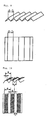
- Fig. 18 is a perspective view showing the emboss design of an interlayer for a laminated glass according to the fifth aspect and Fig. 19 is a plan view of the same.
- the trough-like geometry 1 of the concave portion and segmenting troughs 2 of the convex portion may be provided in a grid or a random configuration but the grid configuration is preferred.
- the depth of segmenting troughs 3 in the convex portion may be uniform or random, although a uniform depth is preferred.
- both sides of the interlayer preferably have an embossment satisfying the herein-defined conditions but an interlayer having an embossment satisfying defined conditions only on one side with the other side having the conventional embossment is also acceptable.
- the concave portions on at least one side have a continual trough-like geometry and even when the geometry of the embossment is destroyed under heat and pressure in the preliminary contact bonding of the glass-interlayer assembly, the continual trough-like geometry of the concave portion persists to the last. Therefore, sufficient deaeration can be achieved.
- the convex portion complementary to the concave portion has segmenting walls and, moreover, the bottom of the segmenting trough is not on one and the same level as the bottom of the continual trough-like geometry of the concave portion, the sealing performance in laminated glass processing canbe improved by controlling the geometry of the segmenting trough of the convex portion. Furthermore, through such control of the geometry of the segmenting trough of the convex portion, the different processing needs of various users can be met with ease and efficiency.
- the sixth aspect is concerned with an interlayer for a laminated glass in which at least one side is provided with concave troughs, and an angle between said concave trough and a direction of extrusion of the thermoplastic resin sheet is less than 25°.
- this angle between the concave trough provided on the thermoplastic resin sheet used in sixth aspect and the extrusion direction of the thermoplastic sheet is too large, bubbling (formation of air bubbles) tends to occur in the laminated glass particularly when the preliminary contact bonding is performed by the drawdeaeration method and, moreover, if the concave trough extends to the edge of the sheet, a sealing defect occurs to entrap air in the final contact bonding which is carried out under heat and pressure in an autoclave. Therefore, said angle is restricted to less than 25°, preferably less than 15°.
- the concave trough mentioned above is a continual trough and when a plurality of troughs are present, they are preferably identical in depth, width and pitch, although there may be a moderate undulation at the bottom of the trough or they may be randomly present, varying in depth, width, and/or pitch.
- the sectional configuration of the concave trough is not particularly restrictedbut each troughmay for example be V-shaped, U-shaped, or bracket-shaped.
- the depth of the trough is preferably 5 to 500 ⁇ m, more preferably 20 to 70 ⁇ m.
- the width of the trough is preferably 20 to 100 ⁇ m, for if it is too narrow, the deaeration performance will be poor and if it is too broad, a sealing defect tends to develop.
- the interval (pitch) of concave troughs is preferably 0.1 to 10 mm, more preferably 0.2 to 1 mm, for if the interval is too small, the deaeration performance will be poor and if it is too large, a sealing defect tends to develop.
- concave troughs need only be formed on at least one side of a thermoplastic resin sheet.
- troughs are preferably formed on both sides.
- thermoplastic resin sheet is formed not only with concave troughs but also with a multiplicity of fine depressions and convex portions as embossed on both sides.
- the distribution of these fine concave and convex may be orderly or not orderly.
- the depth and height of concave and convex may each be uniform throughout or varying.
- concave troughs persist even after the concave and convex of the embossment are abolished by heat and pressure in preliminary contact bonding, particularly in the draw deaeration process in processing laminated glass. Therefore, sufficient deaeration can be insured.
- a route for air can be insured even when, for example, the convex portion is in the form of a mountain ridge, the deaeration passageway is arranged in a grid form, and deaeration is performed at right angles with the mountain ridge. Therefore, even when the deaeration is carried out at right angles with said mountain ridge, the air will not be dammed and, hence, no air pool will be formed.
- the seventh aspect is concerned with an interlayer for a laminated glass in which concave portion on at least one side has a trough-like geometry, and said trough-like geometry is constant in sectional area while has a depth distribution of troughs having a depth of not less than 5% of the maximum trough depth.
- the concave portion on at least one side has the trough-like geometry and, with the depth of the trough being reduced locally, has a depth distribution of troughs having a depth of not less than 5% of the maximum trough depth, while the sectional area of the trough-like geometry is kept constant. Therefore, in the deaeration by the vacuumdeaeration technique, an effective route for air is insured at initiation of deaeration and the shallow parts become more ready to adhere to the glass so that the sealability is improved.
- Troughs having a depth distribution of not less than 5% of the maximum trough depth as mentioned above are preferably provided at an interval (pitch) of not more than 10 mm. If this pitch exceeds 10 mm, the trouble of bubble formation in the marginal part of the glass-interlayer assembly may occur in the course of deaeration.
- the more preferred pitch is not more than 2 mm.
- the trough-like geometry is preferably provided in the direction of flow of the interlayer.
- the "flow direction” means the direction of travel of the glass-interlayer assembly on a laminated glass production line.
- this arrangement not only the molding of the roll to be used for transfer of the trough-like geometry to the interlayer but also the transfer to the substrate interlayer sheet is facilitated.
- this arrangement is preferred in view of the fact that the direction of deaeration in the draw deaeration technique is the flow direction of the interlayer.
- the above trough-like geometry need only be formed on one side of the interlayer in accordance with the seventh aspect of the invention but is preferably present on both sides.
- the trough-like geometry is present on at least one side of the interlayer of the invention, the formation of air bubbles can be prevented by using the interlayer of the invention when, for example, the inner side of the glass has a distribution of roughness or the interlayer is to be used only on the side for absorbing the steps due to black ceramics printing or the like.
- the interlayer according to the seventh aspect can be used with advantage when the deaeration is performed by the vacuum deaeration technique but by increasing the fineness of the trough, for example by reducing the depth of the trough to less than about 30 ⁇ m, it can be used with success when the deaeration is performed by the draw deaeration technique as well.
- the technology of creating said trough-like geometry includes, for example, the method which comprises processing the surface of a metal roll or a flat plate (pressed plate) into a convex (ridge-like) form and transfer the form to a substrate interlayer.
- the depth of the trough can be varied with its sectional area kept constant by indenting the surface ridge of a metal roll or flat plate (pressed plate) locally and particularly the method which comprises biasing a mill having a defined geometry against said surface to vary the depth of the trough is preferred in that the sectional area of the trough can be easily kept constant.
- the surface ridge of a metal roll or flat plate (pressed plate) is machined with a bit or the like to reduce its height, the sectional area of that portion will be decreased.
- the interlayer according to the present invention is used for the manufacture of laminated glass products.
- Such a laminated glass can be obtained by interposing the interlayer of the invention between at least one pair of glass sheets and consolidating the assembly into an integral unit.
- the glass sheet mentioned above is not particularly restrictedbutincludes inorganicglass sheets; andorganicglass sheets such as the polycarbonate sheet, polymethyl methacrylate sheet, and so forth.
- the structure of said laminated glass need only be such that the interlayer of the invention is interposed between two glass sheets and is otherwise not particularly restricted.
- the structure is not restricted to the 3-layer structure of sheet glass/ interlayer/sheet glass but may be a multilayer structure of, for example, sheet glass/interlayer/sheet glass/interlayer/sheet glass.
- the technology of manufacturing a laminated glass product using the interlayer of the invention is not particularly restricted.
- the desired laminated glass can be obtained by the same production technology as used in the manufacture of the conventional laminated glass, for example by interposing the interlayer between at least one pair of glass sheets, subjecting the whole to preliminary contact bonding for deaeration and provisional adhesion, and subjecting it to final contact bonding, for example, in an autoclave.
- the preliminary contact bonding and final contact bonding can for example be carried out in accordance with the following procedures.
- the preliminary contact bonding procedure may comprise interposing the interlayer between two transparent inorganic glass sheets and passing the assembly over a nip roll for preliminary contact bonding with concurrent deaeration for example at a pressure of 2 to 1000 kPa and a temperature of 50 to 100°C (draw deaeration technique) or accommodating said assembly in a rubber bag, connecting the bag to a vacuum system, and evacuating the bag to a vacuum of -40 to -75 kPa (absolute pressure 36 to 1 kPa) while increasing the temperature for preliminary contact bonding at 60 to 100°C (vacuum deaeration technique) .
- the assembly subj ected to the preliminary contact bonding procedure is further subjected to final contact bonding in an autoclave in the conventional manner or by means of a press set to a temperature of 120 to 150°C under a pressure of 200 to 1500 kPa to give the laminated glass.
- polyvinyl butyral resin (average degree of polymerization 1700, residual acetyl group 1 mol %, butyralization degree 65 mol %) was added 40 parts by weight of the plasticizer triethylene glycol-di-2-ethylbutyrate, and using an extruder, the resulting mixture was melt-kneaded and extruded in a sheet form from the extrusion die to give a 0.76 mm-thick polyvinyl butyral resin sheet (PVB sheet).
- PVB sheet polyvinyl butyral resin sheet
- An engraving mill (mother mill) having a linear embossment design (concave and convex patterns) for embossing use was forced against the surface of one of a pair of metal embossing rolls and this metal roll and the engraving roll were driven in association to transfer the embossment design of the engraving mill to the metal roll. Then, the engraving mill was shifted in the axial direction of the metal roll in steps of the unit embossment design to transfer the embossment design of the engraving mill to the metal roll in the same manner as above to construct an embossing roll having an orderly array of linear embossment designs.
- the embossment pitch of the engraving mill was 250 ⁇ m.
- An engraving mill (mother mill) having a linear embossment design was forced against the surface of the other metal roll of saidpair of emboss ing rolls and the metal roll and the engraving mill were driven in association to transfer the embossment design of the engraving mill to the metal roll. Then, the engraving mill was shifted in the axial direction of the metal roll in steps of the unit embossment design to transfer the embossment design of the engraving mill serially to the metal roll in the same manner as the above to construct an embossing roll with an orderly array of linear embossment designs.
- the pitch of the emboss design of said engraving mill was 320 ⁇ m.
- the PVB sheet (0.76 mm thick) obtained as above was passed over the embossing roll pair obtained as above to manufacture an interlayer sheet for laminated glass having an orderly array of linear embossment designs on both sides but varying in the pitch of designs from one side to the other side.
- Example 1 Except that the pitch of the embossment of one engraving mill (mother mill) was changed to 300 ⁇ m and the pitch of the embossment of the other engraving mill (mother mill) was changed to 375 ⁇ m, the procedure of Example 1 was repeated to manufacture an interlayer for a laminated glass having an orderly array of linear embossments on both sides and varying in the pitch of embossments from one side to the other side.
- Example 1 Except that the pitch of the embossments of one engraving mill (mother mill) was changed to 300 ⁇ m and the pitch of the embossments of the other engraving mill (mother mill) was changed to 430 ⁇ m, the procedure of Example 1 was repeated to manufacture an interlayer for a laminated glass having an orderly array of linear embossments on both sides and varying in the pitch of embossments from one side to the other side.
- Example 1 Except that the pitch of the embossments was set to 300 ⁇ m for both engraving mills (mother mills), the procedure of Example 1 was repeated to manufacture an interlayer for a laminated glass having an orderly array of linear embossments on both sides with the same pitch of embossments for both sides.
- polyvinyl butyral resin (average degree of polymerization 1700, residual acetyl group 1 mol %, butyralization degree 65 mol %) was added 40 parts by weight of the plasticizer triethylene glycol-di-2-ethylbutyrate (3GH), and, using an extruder, the resulting mixture was melt-kneaded and extruded in a sheet form from the extrusion die to give a 0.76 mm-thick polyvinyl butyral resin sheet (PVB sheet).
- PVB sheet polyvinyl butyral resin sheet
- An engraving mill (mother mill) having a hemispherical embossment design was forced against the surface of one of a pair of metal embossing rolls and this metal roll and the engraving mill were driven in association to transfer the embossment design of the engraving mill to the metal roll. Then, the engraving mill was shifted in the axial direction of the metal roll in steps of the unit embossment design to transfer the embossment design of the engraving mill to the metal roll in the same manner as above to construct an embossing roll having an orderly array of hemispherical embossments.
- the pitch of the embossments of the engraving mill was 200 ⁇ m.
- An engraving mill (mother mill) having a hemispherical embossment design was forced against the surface of the other metal roll of said pair of embossing rolls and the metal roll and the engraving mill were driven in association to transfer the embossment design of the engraving mill to the metal roll. Then, the engraving mill was shifted in the axial direction of the metal roll in steps of the unit embossment design to transfer the embossment design of the engraving mill serially to the metal roll to construct an embossing roll having an orderly array of hemispherical embossments.
- the pitch of embossments of said engraving mill was 300 ⁇ m.
- the PVB sheet (0.76 mm thick) obtained as above was passed over the embossing roll pair obtained as above to manufacture an interlayer for a laminated glass having an orderly array of hemispherical embossments on both sides but varying in the pitch of embossments from one side to the other side.
- the face side, reverse side and cross-section views of the embossment pattern of the interlayer thus obtained are shown in Fig. 3 .
- Example 4 Except that a linear embossment design was used for engraving mills (mother mills) and the pitch of embossments of one of the engraving mills was set to 250 ⁇ m and that of the other engraving mill to 300 ⁇ m, the procedure of Example 4 was otherwise repeated to manufacture an interlayer for a laminated glass having a linear embossment pattern on both sides and varying in the pitch of embossments from one side to the other side.
- the face side, reverse side, and cross-section views of the embossment design of the interlayer thus obtained are shown in Fig. 4 .
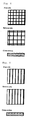
- Example 4 Except that a grid embossment design was used for engraving mills (mother mills) and the pitch of embossments of one of the engraving mills was set to 200 ⁇ m and that of the other engraving mill to 400 ⁇ m, the procedure of Example 4 was otherwise repeated to manufacture an interlayer for a laminated glass having a grid pattern of embossments on either side and varying in the pitch of embossments from one side to the other side.
- the face side, reverse side, and cross-section views of the embossment design of the interlayer thus obtained are shown in Fig. 5 .
- Example 4 Except that a linear embossment design with a pitch of 220 ⁇ m was used for one of the engraving mills (mother mills) and the grid embossment design with a pitch of 320 ⁇ m was used for the other engraving mill, the procedure of Example 4 was otherwise repeated to manufacture an interlayer for a laminated glass having an orderly array of linear embossments on one side and an orderly array of grid embossments on the other side and varying in the pitch of embossments from one side to the other.
- Example 4 Except that a linear embossment design with a pitch of 210 ⁇ m was used for both engraving mills (mother mills), the procedure of Example 4 was otherwise repeated to manufacture an interlayer for a laminated glass having an orderly linear embossment pattern on both sides at the same pitch of embossments for both sides.
- the face side, reverse side, and cross-section views of the embossment design of the interlayer thus obtained are shown in Fig. 6 .
- the interlayer was moved slowly and continuously and the appearance of the moiré phenomenon was visually monitored.
- preliminary contact bonding was carried out by the following two alternative methods (draw deaeration and vacuum deaeration), followed by final contact bonding to fabricate 9 kinds of laminated glass sheets.
- the interlayer was sandwiched between two sheets of transparent float glass (30 cm long x 30 cm wide x 3 mm thick) and the superfluous part was trimmed off.
- the resulting assembly was heated in an oven to an article temperature (preliminary contact bonding temperature) of 60°C, 70°C or 80°C and passed over a nip roll (air cylinder pressure 350 kPa, linear velocity 10 m/min) for preliminary contact bonding.
- the interlayer was sandwiched between two sheets of transparent float glass (30 cm long x 30 cm wide x 3 mm thick) and the superfluous part was trimmed off.
- the resulting assembly was transferred into a rubber bag and, with the rubber bag connected to a suction system, heated by external heating while maintaining at a negative pressure of -60 kPa (absolute pressure 16 kPa) for 10 minutes. After the assembly had been heated to an article temperature (preliminary contact bonding temperature) of 60°C, 80°C or 100°C, the pressure was returned to atmospheric pressure to complete preliminary contact bonding.
- the assembly subjected to preliminary contact bonding by the above method (a) or (b) was held in an autoclave at a temperature of 140°C and a pressure of 1.3 MPa for 10 minutes, at the end of which time the temperature was lowered to 50°C and the pressure was returned to atmospheric pressure to complete the final contact bonding and provide a laminated glass.
- the laminated glass was heated in an oven at 140°C for 2 hours. Then, the glass was taken out of the oven, allowed to cool over 3 hours, and was visually inspected to count the number of sheets with air bubbles and evaluate the deaeration performance. The number of sheets tested was 100 for each glass product. The fewer the number of glass sheets with air bubbles is, the superior is the deaeration and sealing performance. Table 1 Example 1 Example 2 Example 3 Compar. Ex.
- thermoplastic resin sheet "DXN film” (polyvinyl butyral resin sheet, product of Sekisui Chemical) was used.
- a pair of rolls namely a metal roll subjected to surface milling with a triangular oblique line type mill (product of Yuri Roll Co.) and a rubber roll having a JIS hardness of 45 to 75, was used as the surface irregularity transfer device and said DXD film was passed over this surface irregularity transfer device to apply an embossed depression forming a trough design with a continual bottom on one side of the DXN film.
- the transfer conditions used were as follows. Temperature of DXN film: room temperature Roll temperature: 130°C Linear velocity: 10 m/min. Press linear pressure: 500 kPa
- the other side of the DXN film was also subjected to the above treatment to give an interlayer having an orderly linear pattern comprising concave portions with a trough-like configuration continual at the bottom and convex portions each having a plateau-forming top onboth sides.
- the interval (pitch) of the embossed convex portions of the interlayer was 300 ⁇ m
- the width of the plateau-forming top of the embossed convex portion was 250 ⁇ m
- the width of the embossed concave portion was 50 ⁇ m.
- Example 8 Except that the pitch of the embossed convex portions was set to 300 ⁇ m, the width of the plateau-forming topof the embossed convex portion was set to 160 ⁇ m, and the width of the embossed concave portion was set to 140 ⁇ m, the procedure of Example 8 was otherwise repeated to give an interlayer having an orderly linear pattern comprising embossed concave portions having a trough-like configuration continual at the bottom and embossed convex portions each having a plateau-forming top on both sides.
- the procedure of Reference Example 8 was otherwise repeated to give an interlayer having an orderly grid embossment pattern comprising embossed concave portions having a trough-like configuration continual at the bottom and embossed convex portions each having a plateau-forming configuration on both sides.
- Example 8 Except that the interval (pitch) of the embossed convex portions was set to 500 ⁇ m, the width of the plateau-forming top of the embossed convex portion was set to 400 ⁇ m, the width of the embossed concave portion was set to 100 ⁇ m, and a grid configuration was selected for the emboss design, the procedure of Example 8 was otherwise repeated to give an interlayer having an orderly grid embossment pattern comprising embossed concave portions having a trough-like geometry continual at the bottom and embossed convex portions each having a plateau-forming top on both sides.
- the interlayer was sandwiched between two transparent float glass sheets (30 cm long x 30 cm wide x 30 cm thick) and the superfluous part was trimmed off to fabricate a glass-interlayer assembly.
- the assembly was transferred into a rubber bag.
- the rubber bag was connected to a vacuum suction system and heated externally and held at a negative pressure of -60 kPa (absolute pressure 16 kPa) for 10 minutes. The heating was performed until the temperature of the assembly (preliminary contact bonding temperature) had reached 70°C and the pressure was then returned to atmospheric pressure to complete preliminary contact bonding.
- the three different deaeration start temperatures of 40°C, 50°C and 60°C were used at preliminary contact bonding.
- the glass assembly subjected to preliminary contact bonding in the above manner was placed in an autoclave and held at a temperature of 140°C and a pressure of 1300 kPa for 10 minutes. The temperature was then lowered to 50°C and the pressure was returned to atmospheric pressure to complete final contact bonding and give a laminated glass.
- thermoplastic resin sheets DXN films (polyvinyl butyral resin sheet, product of Seisui Chemical) was provided.
- the Ra values of the DXN films used in Reference Examples 12 to 16 are shown in Table 4.
- the above DXN film was passed over this surface irregularity transfer device to give an interlayer for a laminated glass having an embossment pattern on both sides.
- the transfer conditions used namely an embossing roll and a rubber roll, as the surface irregularity transfer device.
- the embossment patterns (concave and convex patterns) of the interlayers for laminated glass as obtained in Reference Examples 12 to 16 are shown in Table 4.
- Fig. 10 shows the embossment pattern (concave and convex patterns) of the interlayers for laminated glass as obtained in Reference Example 12 and Reference Example 13;
- Fig. 11 shows the embossment pattern (concave and convex patterns) of the interlayers for laminated glass as obtained in Reference Example 14 and Reference Example 15; and
- Fig. 12 shows the embossment pattern (concave and convex patterns) of the interlayer for a laminated glass as obtained in Reference Example 16.
- thermoplastic resin sheet polyvinyl butyral resin sheet
- the procedure of Examples was otherwise repeated to give an interlayer for a laminated glass having an embossment pattern on both sides.
- the embossment pattern (concave and convex patterns) of the interlayer for a laminated glass as obtained in Comparative Example 4 is shown in Table 4.
- Fig. 13 is a schematic representation of the embossment pattern (concave and convex patterns) of the interlayer for a laminated glass as obtained in Comparative Example 4.
- the average surface roughness (Ra) of the embossment was measured by the method described below and the average surface roughness (Rz) was measured as in Example 1 for the evaluation of handling workability and self-adhesiveness of the interlayer. The results are shown in Table 4.
- the interlayers for laminated glass according to Reference Examples 15 and 16 where the Ra of the plateau of the convex portion was less than 2.5 um showed slightly higher self-adhesiveness than the interlayers for laminated glass according to Reference Examples to 14 but was of the order which does not matter from practical points of view.
- the interlayer for a laminated glass having no fine irregularities according to Comparative Example in which the ratio (b/a) of the width of the plateau to the pitch of convex portions was less than 20% showed exceedingly high self-adhesiveness as compared with the interlayer for a laminated glass according to the above Examples and the laminated glass manufactured by using this interlayer for a laminated glass showed many sheets with air bubbles (rejects) owing to bubbling in the bake test as compared with the Examples when the deaeration start temperature in preliminary contact bonding was 50°C or higher.
- This result indicates that unless the deaeration start temperature for preliminary contact bonding is strictly controlled to at least below 50°C, the premature marginal sealing of the glass-interlayer assembly takes place so that the air present in the central part of the assembly is not sufficiently removed.
- a longitudinal pattern-engraving mill (mother mill) was pressed against one metal roll of a pair of embossing rolls and the metal roll and the engraving mill were driven in association to transfer the concave and convex patterns of the engraving mill to the metal roll. Then, the engraving mill was shifted serially in the axial direction of the metal roll in steps of the unit design of the concave and convex patterns to construct an embossing roll carrying an orderly array of longitudinal linear patterns. Further, in Reference Example 19 and Reference Example 20, a transverse pattern-engraving mill was used to transfer the transverse design to said metal roll under a load corresponding to 1/10 of the transfer pressure of said longitudinal-pattern engraving mill. In this procedure, the arrangement and size of the respective patterns were monitored under the microscope.
- thermoplastic resin sheet "DXN film” (polyvinyl butyral resin sheet, product of Sekisui Chemical) was used.
- the above embossing roll was paired with a rubber roll and with the embossing roll controlled at 130°C, the above thermosetting resin sheet was passed over the roll set to apply the predetermined emboss pattern.
- the embossed pattern formed on the interlayers for laminated glass as obtained in Reference Example 17 and Reference Example 18 is illustrated in Fig. 14 ; the embossed pattern formed on the interlayers for laminated glass as obtained in Example 19 and Example 20 is illustrated in Fig. 15 ; and the embossed pattern formed on the interlayer for a laminated glass as obtained in Comparative Example 5 is illustrated in Fig. 16 .
- the pitch of convex portions, depth of troughs, pitch of segmenting walls, and height of the segmenting wall of each embossment are shown in Table 5.
- the interlayer was sandwiched between two transparent sheets of transparent float glass (30 cm long x 30 cm wide x 3 mm thick) and the superfluous part was trimmed off.
- the resulting glass-interlayer assembly was transferred into a rubber bag and the rubber bag was connected to a vacuum suction system.
- the bag was heated externally under a negative pressure of -60 kPa (absolute pressure 16 kPa) for 10 minutes, whereby the temperature of the glass-interlayer assembly (preliminary contact bonding temperature) was brought to a predetermined temperature.
- the negative pressure was then returned to atmospheric pressure to complete preliminary contact bonding.
- the deaeration start temperature for the above preliminary contact bonding was set to 50°C and the preliminary contact bonding temperature was set to one of the three levels, 60°C, 65°C, or 70°C.
- the glass-interlayer assembly provisionally bonded by the above procedure was placed in an autoclave and held at a temperature of 140°C and a pressure of 1300 kPa for 10 minutes. Then, the temperature was lowered to 50°C and the pressure was returned to atmospheric pressure to complete final contact bonding and thereby provide a laminated glass.
- the surface of a metal roll was machined with an engraving mill (a linear triangular oblique line cup mill) to form concave and convex patterns (orderly) comprising a multiplicity of concave troughs (linear) triangular in section and the corresponding multiplicity of convex ridges (linear) . Further, using glass beads (#46), the roll was blasted from a distance of about 30 cm at an air pressure of 100 kPa to fabricate an embossing roll.
- an engraving mill a linear triangular oblique line cup mill
- polyvinyl butyral resin 100 parts by weight of polyvinyl butyral resin (average degree of polymerization 1700, residual acetyl group 1 mol %, butyralization degree 65 mol%) was blended with 40 parts by weight of the plasticizer triethylene glycol di-2-ethylbutyrate and 0.2 part by weight of the bond strength modulatormagnesiumacetate, and using an extruder, the resulting mixture was melt-kneaded and extruded from a die in a sheet form to give a 0.76 mm-thick polyvinyl butyral sheet.
- an interlayer was produced by the conventional method, which interlayer consisted of a polyvinyl butyral sheet and, as formed on both sides thereof, concave and convex patterns (orderly) comprising a multiplicity of convex ridges (linear) triangular in cross-section and the corresponding multiplicity of convex troughs (linear), said troughs being not on the same level.
- the water content of this interlayer was adjusted to 0.4 to 0.5 weight %.
- the surface of a metal roll was machined with an engraving mill (pyramidcupmill) to formamultiplicityof concave portions each in the form of a quadrangular pyramid and the corresponding multiplicity of convex portions.
- the roll was further blasted with glass beads (#20) from a distance of about 30 cm at an air pressure of 100 kPa to fabricate an embossing roll.
- the surface of a metal roll was machined with an engraving mill (wavy triangular oblique line cup mill) to form concave and convex patterns (not orderly) comprising a multiplicity of concave troughs (wavy) triangular in cross-section and the corresponding multiplicity of complementary convex ridges (wavy).
- the roll was further blasted with glass beads (#20) from a distance of about 30 cm at an air pressure of 1 kg to fabricate an embossing roll.
- the surface of a metal roll was machined with an engraving mill (linear triangular oblique line cup mill) to form concave and convex patterns (orderly) comprising a multiplicity of concave troughs (linear) triangular in cross-section and the corresponding multiplicity of complementary convex ridges (linear) to thereby fabricate an embossing roll.
- an engraving mill linear triangular oblique line cup mill
- the surface roughness (Rz) of the emboss design was measured by the same method as used in Example 1 and the Rzv of the negative model of the embossment was measured by the method described below.
- laminated glass sheets were manufactured by the following method and subjected to the same bake test as in Example 1 to evaluate deaeration and sealing performances in the preliminary contact bonding stage. The results are collectively shown in Table 6.
- the emboss negative model was taken from each of the above interlayers and the surface roughness Rzv of this negative model was measured using the wedge-shaped tracer (tip width 1000 ⁇ m, opposite face angle 90 ° ) by scanning with the tracer shifted in the direction normal to its tip width in accordance with JIS B 0601.
- Preliminary contact bonding was performed by the following alternative techniques (draw deaeration and vacuum deaeration) and final contact drawing was then performed to manufacture laminated glass sheets.
- the interlayer was sandwiched between two sheets of transparent float glass (30 cm long x 30 cm wide x 2 mm thick; the margin of each glass sheet was curved by 1 mm with respect to the center) and the superfluous part of the interlayer was trimmed off.
- the resulting glass-interlayer assembly was heated in an oven until the temperature of the assembly (preliminary contact bonding temperature) had reached 60°C, 70°C or 80°C and, then, passed over a pair of nip rollers (air cylinder pressure 350 kPa, linear velocity 10 m/min) for preliminary contact bonding.
- the interlayer was sandwiched between two sheets of transparent float glass (30 cm long x 30 cm wide x 2 mm thick; the margin of each panel is curved by 1 mm with respect of the center) and the superfluous part of the interlayer was trimmed off.
- the resulting glass-interlayer assembly was transferred into a rubber bag and the rubber bag was connected to a vacuum suction system. It was then heated externally and held at a negative pressure of -60 kPa (absolute pressure 16 kPa) for 10 minutes, the heating being carried out until the temperature of the assembly (preliminary contact bonding temperature) reached 60°C, 80°C or 100°C. Then, the pressure was returned to atmospheric pressure to complete preliminary contact bonding.
- thermoplastic resin sheet As the thermoplastic resin sheet, DX film (product of Sekisui Chemical) was used.
- the DX film was passed through the surface irregularity transfer device to form a trough-shaped embossment pattern of continual concave portions on one side of the DX film.
- the transfer conditions were as follows. Temperature of DX film: room temperature Roll temperature: 140°C Linear velocity: 10 m/min. Press linear pressure: 2500 kPa
- the other side of the DX film was subjected to the same treatment as above to give an interlayer for a laminated glass having an embossment pattern comprising embossed concave portions with a continual trough-like geometry and embossed convex portions with segmented portions on both sides.
- the interlayer cut to 50 cm x 50 cm was placed in horizontal position on a smooth-surfaced glass plate (50 cm long x 50 cm wide) and a slip glass sheet (10 cm long x 10 cm wide x 2.5 mm thick) was placed in superposition. After 30 seconds, the slip glass sheet was pulled horizontally with a spring balance and the maximum frictional resistance was determined from the spring scale reading. The measurement was made in 5 replicates and the average value was taken as maximum frictional resistance (g). The measurement was performed in an atmosphere of 20°C, 40% RH. The smaller the maximum frictional resistance value is, the superior is the slippage between the glass sheet and the interlayer, which means that the relative positioning of the glass sheet and the interlayer is facilitated in the laminating operation and hence the handling workability is improved.
- Preliminary contact bonding was performed by the two alternative techniques, viz. (a) draw deaeration and (b) vacuum deaeration, just as in Reference Example 21, followed by final contact bonding to produce laminated glass sheets and these sheets were subjected to the bake test.
- the laminated glass sheets of Reference Examples 24 to 26 as manufactured by using the interlayers according to Reference Examples 24 to 26 showed fewer sheets with air bubbles (fewer rejects) in the bake test, regardless of the preliminary contact bonding temperature used in the draw deaeration process or in the vacuum deaeration process. These results indicate good deaeration and sealing in the preliminary contact bonding stage.
- the laminated glass of Comparative Example 7 which was manufactured by using the interlayer for a laminated glass according to Comparative Example 7 without providing segmentation to convex portions of the embossment showed many sheets with air bubbles (many rejects) in the bake test when the preliminary contact bonding temperature was low, whether in the draw deaeration process or in the vacuum deaeration process. This means that the sealing in the preliminary contact bonding stage was not wholesome, thus causing insufficient deaeration. Moreover, the result indicates that there are limitations on the manufacturing conditions which can be used in the preliminary contact bonding stage.
- Fig. 20 shows an interlayer embodying the principles of the present invention, where (a) is a plan view and (b) is a side elevation view.
- the interlayer 1 of the invention comprises an extrusion-molded thermoplastic resin sheet provided with a plurality of embossments 3 comprising fine concave portions and convex portions (not shown) on both sides and concave troughs 2 on one side, said concave troughs 2 being disposed generally in parallel with the direction of extrusion X of the thermoplastic resin sheet.
- thermoplastic resin sheet as obtained by extrusion of plasticized polyvinyl butyral resin (product of Sekisui Chemical: trade name "S-Rec Film DXN", 760 ⁇ m thick) was passed through a surface irregularity transfer device comprising a pair of rolls, namely a metal roll formed with prismatic ridges (height: 120 ⁇ m, base 150 ⁇ m, pitch: 300 ⁇ m) complementary with the concave troughs 2 illustrated in Fig.
- plasticized polyvinyl butyral resin product of Sekisui Chemical: trade name "S-Rec Film DXN”, 760 ⁇ m thick
- a surface irregularity transfer device comprising a pair of rolls, namely a metal roll formed with prismatic ridges (height: 120 ⁇ m, base 150 ⁇ m, pitch: 300 ⁇ m) complementary with the concave troughs 2 illustrated in Fig.
- the interlayer was sandwiched between two sheets of transparent float glass (30 cm long x 30 cm wide x 2 mm thick; glass sheets with the margin curved by 1 mm with respect to the center) and the superfluous part was trimmed off.
- the resulting assembly was heated in an oven until the temperature of the assembly had reached 70°C, 80°C or 90°C and, then, passed over a nip roll (air cylinder pressure 35.5 MPa, linear velocity 10 m/min) for preliminary contact bonding.
- the interlayer was sandwiched between two sheets transparent float glass (30 cm long x 30 cm wide x 2 mm thick; glass sheets with the margin curved by 1 mm with respect to the center) and the superfluous part was trimmed off.
- the resulting assembly was transferred into a rubber bag and the rubber bag was connected to a vacuum system.
- the assembly was heated externally under a negative pressure of -60 kPa (absolute pressure 16 kPa) for 10 minutes until the temperature of the assembly (preliminary contact bonding temperature) had reached 70°C, 80°C or 90°C. The pressure was then returned to atmospheric pressure to complete preliminary contact bonding.
- the surface of another metal roll was impressed with a triangular mill to form 200 ⁇ m-deep troughs on the surface of the metal roll and further impres sed wi th a perpendicular triangular mill to prepare a roll surface reduced by 15 ⁇ m in depth of the troughs (corresponding to the bottom surface in the interlayer) .
- this roll surface was geometrically transferred to the surface of the interlayer having said random embossment to give an interlayer having 40 ⁇ m-deep, 80 ⁇ m-wide troughs at a pitch of 500 ⁇ m within 55 ⁇ m-deep, 60 ⁇ m-wide troughs formed at a trough pitch of 300 ⁇ m.
- Example 28 Except that the pressure used for the geometric transfer of the metal roll surface to the substrate interlayer surface was altered, the procedure of Example 28 was otherwise repeated to give an interlayer having a random embossment with a roughness of 30 ⁇ m as well as 50 ⁇ m-deep, 70 ⁇ m-wide troughs formed at a pitch of 500 ⁇ m within 55 ⁇ m-deep, 60 ⁇ m-wide troughs.
- Example 28 The pressure used for the geometric transfer of the metal roll surface to the substrate interlayer surface was altered and the troughs were not formed, the procedure of Example 28 was repeated to give an interlayer having a random embossment with a surface roughness of 55 ⁇ m.
- a metal roll was machined to form the embossing pattern consisting of a uniform array of quadrangular pyramids and the surface of this metal roll was geometrically transferred to a substrate interlayer sheet surface to give an interlayer with a surface roughness of 70 ⁇ m.
- each interlayer was sandwiched between two transparent 2 mm-thick glass sheets and the resulting glass-interlayer assembly was put in a rubber bag set to the initial temperature indicated in Table 9.
- the rubber bag was connected to a vacuum suction system and the evacuation was started. The reduced pressure was maintained for about 10 minutes and the assembly was heated to the ultimate temperature indicated in Table 9. After cooling, the laminated glass was taken out and examined for air bubbles. The case in which no air bubble was found was rate O and the case in which air bubbles were observed was rated X.
- the evacuation initial temperature can be set high and the ultimate temperature can be set low, so that an improved deaeration efficiency can be obtained in preliminary contact bonding.
- the present invention is constituted as described above, there is no moiré phenomenon so that there can be provided an interlayer for a laminated glass with good workability in cutting and laminating operations and excellent deaeration characteristic in preliminary contact bonding.
- the trouble of premature marginal sealing does not take place even if the deaeration initial temperature in preliminary contact bonding is not critically controlled so that an interlayer for a laminated glass with an excellent deaeration effect can be provided. Moreover, since the self-adhesion of the interlayer can be controlled, the interlayer has good handling characteristics.
- the invention provides an interlayer for a laminated glass which is not only good in workability in terms of blocking resistance during storage and handling in laminating work but also excellent in the deaeration and sealing characteristics in preliminary contact bonding. Therefore, particularly in the manufacture of large-area or large-radius-of-curvature laminated glass or for increased productivity of laminated glass production, both deaeration and sealing between the glass and interlayer are sufficiently effected so that the trouble of formation of air bubbles between the glass and interlayer due to infiltration of pressuri zed air through the sealing defect in the final contact bonding under heating and pressure in an autoclave and the consequent incidence of rejects can be largely obviated, thus laminated glass products with particularly high transparency can be obtained.
- the laminated glass products, manufactured by using the interlayer for a laminated glass according to the invention are of high quality almost free of the air bubble problem even when manufactured under rigorously restricted conditions and can be used with advantage in the glazing of the windows of cars, rolling stock, aircraft, buildings and so forth.
Claims (4)
- Couche intermédiaire pour un verre feuilleté
qui comprend une feuille de résine thermoplastique pourvue de reliefs comprenant des parties concaves et des parties convexes sur les deux côtés de celle-ci,
un pas de reliefs sur un côté étant différent d'un pas de reliefs sur l'autre côté,
caractérisée en ce que les parties concaves sur au moins un côté sont continues. - Couche intermédiaire pour un verre feuilleté selon la revendication 1,
dans laquelle les fonds des parties concaves sur au moins un côté sont continus. - Couche intermédiaire pour un verre feuilleté selon l'une quelconque des revendications 1 à 2,
dans laquelle le pas (L1) de reliefs sur un côté et le pas (L2) de reliefs sur l'autre côté satisfont la relation (L1 < (L2), et
la proportion d'existence d'une partie convexe sur l'autre côté dans la plage (L1 x 0,25) d'avant et après une position d'une partie convexe sur un côté n'est pas supérieure à 50 % du nombre de parties convexes sur un côté. - Couche intermédiaire pour un verre feuilleté selon l'une quelconque des revendications 1 à 3,
dans laquelle les parties concaves sur au moins un côté sont formées dans une configuration linéaire.
Applications Claiming Priority (10)
| Application Number | Priority Date | Filing Date | Title |
|---|---|---|---|
| JP18762799A JP5013629B2 (ja) | 1999-07-01 | 1999-07-01 | 合わせガラス用中間膜 |
| JP11201747A JP2001026468A (ja) | 1999-07-15 | 1999-07-15 | 合わせガラス用中間膜 |
| JP11218796A JP2001048599A (ja) | 1999-08-02 | 1999-08-02 | 合わせガラス用中間膜 |
| JP34217299A JP3913948B2 (ja) | 1999-12-01 | 1999-12-01 | 熱可塑性樹脂中間膜 |
| JP34767599A JP2001163641A (ja) | 1999-12-07 | 1999-12-07 | 熱可塑性樹脂中間膜 |
| JP2000000900A JP2001192244A (ja) | 2000-01-06 | 2000-01-06 | 合わせガラス用中間膜 |
| JP2000004685 | 2000-01-13 | ||
| JP2000026652A JP2001220182A (ja) | 2000-02-03 | 2000-02-03 | 合わせガラス用中間膜 |
| EP08152804.4A EP1932661B1 (fr) | 1999-07-01 | 2000-07-03 | Couche intermédiaire pour vitrages feuilletés |
| EP00940918A EP1233007B1 (fr) | 1999-07-01 | 2000-07-03 | Couche intermédiaire pour vitrages feuilletés |
Related Parent Applications (3)
| Application Number | Title | Priority Date | Filing Date |
|---|---|---|---|
| EP00940918.6 Division | 2000-07-03 | ||
| EP08152804.4A Division-Into EP1932661B1 (fr) | 1999-07-01 | 2000-07-03 | Couche intermédiaire pour vitrages feuilletés |
| EP08152804.4 Division | 2008-03-14 |
Publications (2)
| Publication Number | Publication Date |
|---|---|
| EP2292427A1 EP2292427A1 (fr) | 2011-03-09 |
| EP2292427B1 true EP2292427B1 (fr) | 2012-05-23 |
Family
ID=27573382
Family Applications (3)
| Application Number | Title | Priority Date | Filing Date |
|---|---|---|---|
| EP08152804.4A Expired - Lifetime EP1932661B1 (fr) | 1999-07-01 | 2000-07-03 | Couche intermédiaire pour vitrages feuilletés |
| EP00940918A Expired - Lifetime EP1233007B1 (fr) | 1999-07-01 | 2000-07-03 | Couche intermédiaire pour vitrages feuilletés |
| EP20100180354 Expired - Lifetime EP2292427B1 (fr) | 1999-07-01 | 2000-07-03 | Feuille intercalaire pour vitrage feuilleté |
Family Applications Before (2)
| Application Number | Title | Priority Date | Filing Date |
|---|---|---|---|
| EP08152804.4A Expired - Lifetime EP1932661B1 (fr) | 1999-07-01 | 2000-07-03 | Couche intermédiaire pour vitrages feuilletés |
| EP00940918A Expired - Lifetime EP1233007B1 (fr) | 1999-07-01 | 2000-07-03 | Couche intermédiaire pour vitrages feuilletés |
Country Status (9)
| Country | Link |
|---|---|
| US (4) | US6863956B1 (fr) |
| EP (3) | EP1932661B1 (fr) |
| KR (2) | KR100665906B1 (fr) |
| AU (1) | AU780388B2 (fr) |
| BR (1) | BR0012098B1 (fr) |
| CA (1) | CA2376547C (fr) |
| DE (1) | DE60039250D1 (fr) |
| MX (1) | MXPA02000125A (fr) |
| WO (1) | WO2001002316A1 (fr) |
Families Citing this family (73)
| Publication number | Priority date | Publication date | Assignee | Title |
|---|---|---|---|---|
| US7351468B2 (en) * | 2000-10-26 | 2008-04-01 | E. I. Du Pont De Nemours And Company | Interlayers for laminated safety glass with superior de-airing and laminating properties and process for making the same |
| JP4754099B2 (ja) * | 2001-06-05 | 2011-08-24 | 日本合成化学工業株式会社 | 水溶性エンボスフィルムの製造方法 |
| JP4754100B2 (ja) * | 2001-06-05 | 2011-08-24 | 日本合成化学工業株式会社 | 水溶性エンボスフィルムの製造方法 |
| US7704342B2 (en) | 2001-12-27 | 2010-04-27 | Solutia, Inc. | Glass lamination process |
| JP2004250704A (ja) * | 2003-02-19 | 2004-09-09 | Newfrey Llc | 合成熱可塑性プラスチック材料のディスク形状物体及びこれを製造する方法 |
| DE10346505A1 (de) * | 2003-10-02 | 2005-01-05 | Eckelt Glas Gmbh | Lichtdurchlässige Scheibe mit Muster und optischem Effekt |
| US8551600B2 (en) | 2005-02-22 | 2013-10-08 | Solutia Inc. | Low distortion interlayer |
| US7678441B2 (en) | 2005-12-02 | 2010-03-16 | E.I. Du Pont De Nemours And Company | Interlayers for laminated safety glass with superior de-airing and laminating properties and process for making the same |
| ATE422408T1 (de) * | 2006-04-03 | 2009-02-15 | Kuraray Europe Gmbh | Verfahren zur herstellung einer einseitig geprägten folie auf basis von teilacetalisiertem polyvinylalkohol |
| JP4739108B2 (ja) * | 2006-04-27 | 2011-08-03 | 東芝機械株式会社 | 精密ロール旋盤 |
| JP4837448B2 (ja) * | 2006-06-14 | 2011-12-14 | 東芝機械株式会社 | 精密ロール旋盤 |
| JP4786432B2 (ja) * | 2006-06-15 | 2011-10-05 | 東芝機械株式会社 | 精密ロール旋盤 |
| EP1876016A1 (fr) * | 2006-07-07 | 2008-01-09 | Kuraray Europe GmbH | Feuille en plastique gaufré pour vitrage feuilleté |
| US7851694B2 (en) * | 2006-07-21 | 2010-12-14 | E. I. Du Pont De Nemours And Company | Embossed high modulus encapsulant sheets for solar cells |
| US7768598B2 (en) * | 2007-03-06 | 2010-08-03 | Toppan Printing Co., Ltd. | Substrate having pattern, color filter, liquid crystal display and method of manufacturing color filter |
| TW200920521A (en) * | 2007-04-05 | 2009-05-16 | Toshiba Machine Co Ltd | Method and apparatus for machining surface of roll |
| US20080254302A1 (en) * | 2007-04-13 | 2008-10-16 | David Paul Bourcier | Multiple layer polymer interlayers having a melt fractured surface |
| US20080268204A1 (en) * | 2007-04-29 | 2008-10-30 | David Paul Bourcier | Multiple layer polymer interlayers having an embossed surface |
| US20080268270A1 (en) * | 2007-04-30 | 2008-10-30 | Wenjie Chen | High impact polymer interlayers |
| JP5344116B2 (ja) * | 2008-01-09 | 2013-11-20 | セントラル硝子株式会社 | プラスチックフィルム挿入合せガラス |
| WO2009131195A1 (fr) * | 2008-04-23 | 2009-10-29 | 積水化学工業株式会社 | Film intermédiaire pour verre feuilleté et verre feuilleté |
| JP5355950B2 (ja) | 2008-07-17 | 2013-11-27 | 東芝機械株式会社 | V溝加工方法および装置 |
| US20100112355A1 (en) * | 2008-11-06 | 2010-05-06 | Cessna Aircraft Company | Aircraft Transparency |
| KR100984136B1 (ko) | 2008-12-02 | 2010-09-28 | 에스케이씨 주식회사 | 태양전지 모듈용 봉지재 시트 및 이를 포함하는 태양전지 모듈 |
| KR101899412B1 (ko) * | 2010-01-12 | 2018-09-17 | 니폰 덴키 가라스 가부시키가이샤 | 유리 필름 적층체와 그 제조 방법 및 유리 필름의 제조 방법 |
| DE102012209939A1 (de) | 2012-06-13 | 2013-12-19 | Kuraray Europe Gmbh | Geprägte Kunststofffolien für Verbundverglasungen |
| WO2014021459A1 (fr) * | 2012-08-02 | 2014-02-06 | 積水化学工業株式会社 | Film intermédiaire pour verre stratifié, et verre stratifié |
| US9248628B2 (en) | 2013-02-07 | 2016-02-02 | Solutia Inc. | Glass laminate using textured adhesive |
| US9574028B2 (en) * | 2013-04-09 | 2017-02-21 | Solutia Inc. | Embossed polymer sheet |
| KR20140141815A (ko) * | 2013-05-31 | 2014-12-11 | 삼성전자주식회사 | 전자기기용 케이스 및 이의 표면 처리방법 |
| WO2015015601A1 (fr) * | 2013-07-31 | 2015-02-05 | 株式会社クラレ | Film de poly(acétal de vinyle) ayant une transparence et une résistance au phénomène de fissuration thermique exceptionnelles |
| US10870254B2 (en) | 2013-08-01 | 2020-12-22 | Sekisui Chemical Co., Ltd. | Interlayer film for laminated glass and laminated glass |
| KR20160040137A (ko) * | 2013-08-01 | 2016-04-12 | 세키스이가가쿠 고교가부시키가이샤 | 합판 유리용 중간막 및 합판 유리 |
| CN105431394B (zh) | 2013-08-01 | 2019-06-04 | 积水化学工业株式会社 | 车辆用挡风玻璃 |
| EP3029003A4 (fr) * | 2013-08-01 | 2017-03-22 | Sekisui Chemical Co., Ltd. | Couche intermédiaire pour verre feuilleté et verre feuilleté |
| WO2015084902A1 (fr) * | 2013-12-06 | 2015-06-11 | Corning Incorporated | Procédés de formation de motifs dans des structures feuilletées en verre fin |
| CN111763017A (zh) * | 2014-04-09 | 2020-10-13 | 积水化学工业株式会社 | 夹层玻璃用中间膜、辊状体、夹层玻璃及夹层玻璃的制造方法 |
| US9969145B2 (en) * | 2014-04-09 | 2018-05-15 | Sekisui Chemical Co., Ltd. | Vehicle-windshield-glass intermediate film, rolled body, and vehicle windshield glass |
| MX2016015601A (es) * | 2014-06-25 | 2017-02-27 | Sekisui Chemical Co Ltd | Lamina de resina termoplastica con relieve, rodillo grabado, metodo de fabricacion de rodillo grabado, capa intermedia de vidrio laminado, y vidrio laminado. |
| EP3186059B1 (fr) * | 2014-08-25 | 2018-11-28 | Kuraray Europe GmbH | Procédé de production de films gaufrés à base de poly(acétal de vinyle) plastifié |
| US10913234B2 (en) * | 2014-08-29 | 2021-02-09 | Clopay Plastic Products Company, Inc. | Embossed matte and glossy plastic film and methods of making same |
| MX2017003743A (es) | 2014-09-30 | 2017-06-30 | Sekisui Chemical Co Ltd | Pelicula intercapa para vidrio laminado, y vidrio laminado. |
| CN106164009A (zh) * | 2014-09-30 | 2016-11-23 | 积水化学工业株式会社 | 夹层玻璃用中间膜、卷状体、夹层玻璃、夹层玻璃用中间膜的制造方法、以及卷状体的制造方法 |
| CN106164010B (zh) * | 2014-09-30 | 2021-02-05 | 积水化学工业株式会社 | 夹层玻璃用中间膜及夹层玻璃 |
| US11453194B2 (en) | 2014-10-10 | 2022-09-27 | Sekisui Chemical Co., Ltd. | Interlayer film for laminated glass, and laminated glass |
| US20160297169A1 (en) * | 2015-04-08 | 2016-10-13 | Asahi Glass Company, Limited | Laminated plate |
| CA2977440A1 (fr) * | 2015-04-10 | 2016-10-13 | Sekisui Chemical Co., Ltd. | Couche intermediaire pour verre feuillete, verre feuillete, procede de production de rouleau gaufreur, et procede de production de couche intermediaire pour verre feuillete |
| EP3851275A1 (fr) * | 2015-04-10 | 2021-07-21 | Sekisui Chemical Co., Ltd. | Couche intermédiaire pour verre feuilleté, verre feuilleté et procédé de production d'une couche intermédiaire pour verre feuilleté |
| KR20230066131A (ko) | 2015-04-15 | 2023-05-12 | 세키스이가가쿠 고교가부시키가이샤 | 합판 유리용 중간막 및 합판 유리 |
| US10300681B2 (en) * | 2015-07-31 | 2019-05-28 | Sekisui Chemical Co., Ltd. | Intermediate film for laminated glass, method for producing intermediate film for laminated glass, and laminated glass |
| JP6720741B2 (ja) * | 2015-08-07 | 2020-07-08 | Agc株式会社 | 積層板および中間膜 |
| US10596784B2 (en) * | 2015-09-28 | 2020-03-24 | Sekisui Chemical Co., Ltd. | Interlayer for laminated glass and laminated glass |
| AU2016332384A1 (en) * | 2015-09-30 | 2018-03-15 | Sekisui Chemical Co., Ltd. | Interlayer for laminated glass, and laminated glass |
| EP3438070B1 (fr) * | 2016-03-31 | 2021-01-06 | Sekisui Chemical Co., Ltd. | Couche intermédiaire pour verre feuilleté et verre feuilleté |
| MX2018010692A (es) * | 2016-03-31 | 2019-01-17 | Sekisui Chemical Co Ltd | Capa intermedia para vidrio laminado, y vidrio laminado. |
| JP2020503192A (ja) * | 2016-12-29 | 2020-01-30 | サン−ゴバン グラス フランス | ヘッドアップディスプレイ(hud)用pvbフィルム、並びにその成形型及び成形方法 |
| JP2020536832A (ja) * | 2017-10-12 | 2020-12-17 | トレデガー フィルム プロダクツ エルエルシー | 基材間のインターリーフとして使用されるフィルム |
| KR102046252B1 (ko) * | 2018-04-30 | 2019-11-18 | 에스케이씨 주식회사 | 접합유리용 필름, 이를 포함하는 접합유리 및 이의 제조방법 |
| KR102041046B1 (ko) * | 2018-04-30 | 2019-11-05 | 에스케이씨 주식회사 | 접합유리용 필름, 이를 포함하는 접합유리 및 이의 제조방법 |
| KR102066796B1 (ko) * | 2018-07-06 | 2020-01-15 | 에스케이씨 주식회사 | 유리접합필름의 패턴 제조방법 및 이를 포함하는 전사장치 |
| BR112021014303A2 (pt) * | 2019-01-22 | 2022-02-15 | Tredegar Surface Prot Llc | Películas para uso como entrefolhas entre substratos |
| KR102250607B1 (ko) * | 2019-10-04 | 2021-05-10 | 에스케이씨 주식회사 | 유리접합용 필름 및 이를 포함하는 광투과 적층체 |
| KR102281628B1 (ko) * | 2019-11-25 | 2021-07-23 | 에스케이씨 주식회사 | 접합용 필름 및 이를 포함하는 광투과 적층체 |
| CN113207287A (zh) * | 2019-11-28 | 2021-08-03 | 法国圣戈班玻璃厂 | 具有嵌入在热塑性中间层中的功能元件和排气结构的复合玻璃板 |
| US11136441B2 (en) * | 2019-11-29 | 2021-10-05 | Chang Chun Petrochemical Co., Ltd. | Polymer film and uses of the same |
| US11426981B2 (en) * | 2019-11-29 | 2022-08-30 | Chang Chun Petrochemical Co., Ltd. | Polymer film and uses of the same |
| CN112876794B (zh) * | 2019-11-29 | 2023-02-28 | 长春石油化学股份有限公司 | 聚合物膜及其应用 |
| WO2021112625A2 (fr) * | 2019-12-06 | 2021-06-10 | 에스케이씨 주식회사 | Film de liaison et stratifié transmettant la lumière comprenant ce dernier |
| KR102363360B1 (ko) * | 2019-12-06 | 2022-02-14 | 에스케이씨 주식회사 | 접합용 필름 및 이를 포함하는 광투과 적층체 |
| WO2021204550A1 (fr) | 2020-04-07 | 2021-10-14 | Saint-Gobain Glass France | Couche intermédiaire thermoplastique colorée à section transversale en forme de coin |
| US20230127785A1 (en) | 2020-04-07 | 2023-04-27 | Saint-Gobain Glass France | Multilayer colored intermediate layer having a wedge-shaped cross-section |
| US20230117573A1 (en) * | 2021-10-18 | 2023-04-20 | Chang Chun Petrochemical Co., Ltd. | Polymer film and uses of the same |
| CN116277825A (zh) * | 2023-03-14 | 2023-06-23 | 中山博锐斯新材料股份有限公司 | 一种排气型夹胶玻璃用tpu薄膜生产方法 |
Family Cites Families (27)
| Publication number | Priority date | Publication date | Assignee | Title |
|---|---|---|---|---|
| US2512310A (en) * | 1949-01-28 | 1950-06-20 | William G Corson | Rubber floor mat |
| US3911187A (en) * | 1973-12-26 | 1975-10-07 | Ethyl Corp | Embossed plastic film |
| US4135023A (en) * | 1974-06-21 | 1979-01-16 | Smith & Nephew Plastics Ltd. | Embossed film product and adhesive coated strip formed therefrom |
| US4035549A (en) | 1975-05-19 | 1977-07-12 | Monsanto Company | Interlayer for laminated safety glass |
| GB1603865A (en) * | 1977-07-08 | 1981-12-02 | Smith & Nephew Plastics | Production of net |
| JPS57150532A (en) | 1981-03-12 | 1982-09-17 | Mitsubishi Monsanto Chem Co | Intermediate membrane made of thermoplastic resin |
| JPS5939748A (ja) * | 1982-08-31 | 1984-03-05 | Asahi Glass Co Ltd | 合せガラスの製法 |
| JPS60204643A (ja) * | 1984-03-30 | 1985-10-16 | Sekisui Chem Co Ltd | 合せガラス用中間膜 |
| US4925725A (en) * | 1984-03-30 | 1990-05-15 | Sekisui Kagaku Kogyo Kabushiki Kaisha | Interlayer for laminated glass |
| JPS6432776A (en) | 1987-07-29 | 1989-02-02 | Toshiba Corp | Liquid crystal panel driving signal generating circuit |
| AU621471B2 (en) * | 1989-03-31 | 1992-03-12 | Sekisui Kagaku Kogyo Kabushiki Kaisha | A method for the manufacture of thermoplastic resin sheets |
| US5091258A (en) | 1990-08-20 | 1992-02-25 | Monsanto Company | Laminate for a safety glazing |
| JPH05294679A (ja) | 1992-04-16 | 1993-11-09 | Sekisui Chem Co Ltd | 合わせガラス用中間膜及び製造方法 |
| JPH06127983A (ja) | 1992-10-20 | 1994-05-10 | Sekisui Chem Co Ltd | 合わせガラス用中間膜 |
| JP3327990B2 (ja) * | 1992-11-13 | 2002-09-24 | 積水化学工業株式会社 | 合わせガラス用中間膜 |
| US5425977A (en) * | 1993-08-16 | 1995-06-20 | Monsanto Company | Rough-surfaced interlayer |
| US5455103A (en) * | 1994-01-24 | 1995-10-03 | Monsanto Company | Rough-surfaced interlayer |
| BE1008385A3 (nl) * | 1994-05-30 | 1996-04-02 | Tale Consultants Ltd | Werkwijze voor het vervaardigen van gelaagd glas en werkwijze voor het vervaardigen van een daarbij gebruikt vel van polyvinylbutyral. |
| CA2162243A1 (fr) | 1994-11-07 | 1996-05-08 | Jiro Miyai | Pellicule intercouche et verre feuillete fabrique d'apres la meme methode |
| JP3414592B2 (ja) | 1996-03-07 | 2003-06-09 | 積水化学工業株式会社 | 合わせガラス用中間膜 |
| US5888650A (en) * | 1996-06-03 | 1999-03-30 | Minnesota Mining And Manufacturing Company | Temperature-responsive adhesive article |
| US6042928A (en) | 1996-09-02 | 2000-03-28 | Mitsubishi Plastics Inc. | Fluorocarbon resin sheet and glass laminate |
| JPH11147735A (ja) * | 1997-11-13 | 1999-06-02 | Sekisui Chem Co Ltd | 合わせガラス用中間膜 |
| JP2000007390A (ja) | 1998-06-18 | 2000-01-11 | Sekisui Chem Co Ltd | 合わせガラス用中間膜 |
| US6093471A (en) * | 1999-02-08 | 2000-07-25 | Solutia Inc. | Polyvinyl butyral sheet |
| JP2000256044A (ja) * | 1999-03-08 | 2000-09-19 | Sekisui Chem Co Ltd | 合わせガラス用中間膜の製造方法 |
| JP2000256043A (ja) * | 1999-03-09 | 2000-09-19 | Sekisui Chem Co Ltd | 合わせガラス用中間膜および合わせガラス |
-
2000
- 2000-07-03 US US10/019,656 patent/US6863956B1/en not_active Expired - Lifetime
- 2000-07-03 EP EP08152804.4A patent/EP1932661B1/fr not_active Expired - Lifetime
- 2000-07-03 KR KR1020017016819A patent/KR100665906B1/ko active IP Right Grant
- 2000-07-03 BR BRPI0012098-7A patent/BR0012098B1/pt not_active IP Right Cessation
- 2000-07-03 EP EP00940918A patent/EP1233007B1/fr not_active Expired - Lifetime
- 2000-07-03 KR KR1020067021276A patent/KR100680578B1/ko active IP Right Grant
- 2000-07-03 CA CA 2376547 patent/CA2376547C/fr not_active Expired - Lifetime
- 2000-07-03 EP EP20100180354 patent/EP2292427B1/fr not_active Expired - Lifetime
- 2000-07-03 MX MXPA02000125A patent/MXPA02000125A/es active IP Right Grant
- 2000-07-03 DE DE60039250T patent/DE60039250D1/de not_active Expired - Lifetime
- 2000-07-03 AU AU23080/01A patent/AU780388B2/en not_active Ceased
- 2000-07-03 WO PCT/JP2000/004383 patent/WO2001002316A1/fr active IP Right Grant
-
2004
- 2004-02-26 US US10/786,367 patent/US20040191482A1/en not_active Abandoned
-
2005
- 2005-09-01 US US11/216,125 patent/US7150905B2/en not_active Expired - Lifetime
-
2006
- 2006-10-26 US US11/586,577 patent/US7378142B2/en not_active Expired - Lifetime
Also Published As
| Publication number | Publication date |
|---|---|
| EP1233007A4 (fr) | 2004-05-06 |
| WO2001002316A8 (fr) | 2001-03-22 |
| EP1932661B1 (fr) | 2016-03-16 |
| AU780388B2 (en) | 2005-03-17 |
| MXPA02000125A (es) | 2002-07-30 |
| US7150905B2 (en) | 2006-12-19 |
| EP1233007B1 (fr) | 2008-06-18 |
| KR100680578B1 (ko) | 2007-02-08 |
| DE60039250D1 (de) | 2008-07-31 |
| KR100665906B1 (ko) | 2007-01-09 |
| AU2308001A (en) | 2001-01-22 |
| US20070042160A1 (en) | 2007-02-22 |
| US7378142B2 (en) | 2008-05-27 |
| EP2292427A1 (fr) | 2011-03-09 |
| US6863956B1 (en) | 2005-03-08 |
| EP1932661A1 (fr) | 2008-06-18 |
| BR0012098A (pt) | 2003-04-29 |
| BR0012098B1 (pt) | 2009-05-05 |
| US20050287341A1 (en) | 2005-12-29 |
| US20040191482A1 (en) | 2004-09-30 |
| CA2376547A1 (fr) | 2001-11-01 |
| WO2001002316A1 (fr) | 2001-01-11 |
| CA2376547C (fr) | 2006-09-12 |
| EP1233007A1 (fr) | 2002-08-21 |
| KR20060110016A (ko) | 2006-10-23 |
| KR20020020759A (ko) | 2002-03-15 |
Similar Documents
| Publication | Publication Date | Title |
|---|---|---|
| EP2292427B1 (fr) | Feuille intercalaire pour vitrage feuilleté | |
| JPH05147981A (ja) | 合わせガラス用中間膜 | |
| CN105473527A (zh) | 层合玻璃用中间膜及层合玻璃 | |
| JP3913948B2 (ja) | 熱可塑性樹脂中間膜 | |
| ZA200200307B (en) | Interlayer for laminated glass and laminated glass. | |
| JP3895950B2 (ja) | 合わせガラス用中間膜 | |
| AU2005200410B2 (en) | Interlayer for laminated glass and laminated glass | |
| JP2001048599A (ja) | 合わせガラス用中間膜 | |
| JP2000203901A (ja) | 合わせガラス用中間膜 | |
| JP2001163641A (ja) | 熱可塑性樹脂中間膜 | |
| CA2549785C (fr) | Couche intermediaire pour verres stratifies et verre stratifie | |
| JP2000007390A (ja) | 合わせガラス用中間膜 | |
| JP2001261385A (ja) | 合わせガラス用中間膜 | |
| JP2001192244A (ja) | 合わせガラス用中間膜 | |
| JP2000203902A (ja) | 合わせガラス用中間膜 | |
| JP2002037648A (ja) | 合わせガラス用中間膜及び合わせガラス | |
| JPH10231150A (ja) | 合わせガラス用中間膜 | |
| CN114096407B (zh) | 接合用层合薄膜、包括该薄膜的透光层叠体及包括该透光层叠体的交通工具 | |
| JP2000319045A (ja) | 合わせガラス用中間膜及び合わせガラス | |
| JP2000256044A (ja) | 合わせガラス用中間膜の製造方法 | |
| JPH1017338A (ja) | 合わせガラス用中間膜 | |
| JPH08143346A (ja) | 合わせガラス用中間膜の製造方法 | |
| JPH11147735A (ja) | 合わせガラス用中間膜 | |
| JP2003286049A (ja) | 合わせガラス用中間膜及び合わせガラス | |
| JP2001026468A (ja) | 合わせガラス用中間膜 |
Legal Events
| Date | Code | Title | Description |
|---|---|---|---|
| PUAI | Public reference made under article 153(3) epc to a published international application that has entered the european phase |
Free format text: ORIGINAL CODE: 0009012 |
|
| 17P | Request for examination filed |
Effective date: 20100927 |
|
| AC | Divisional application: reference to earlier application |
Ref document number: 1233007 Country of ref document: EP Kind code of ref document: P Ref document number: 1932661 Country of ref document: EP Kind code of ref document: P |
|
| AK | Designated contracting states |
Kind code of ref document: A1 Designated state(s): BE DE FR GB IT NL |
|
| GRAP | Despatch of communication of intention to grant a patent |
Free format text: ORIGINAL CODE: EPIDOSNIGR1 |
|
| GRAS | Grant fee paid |
Free format text: ORIGINAL CODE: EPIDOSNIGR3 |
|
| GRAA | (expected) grant |
Free format text: ORIGINAL CODE: 0009210 |
|
| AC | Divisional application: reference to earlier application |
Ref document number: 1233007 Country of ref document: EP Kind code of ref document: P Ref document number: 1932661 Country of ref document: EP Kind code of ref document: P |
|
| AK | Designated contracting states |
Kind code of ref document: B1 Designated state(s): BE DE FR GB IT NL |
|
| REG | Reference to a national code |
Ref country code: GB Ref legal event code: FG4D |
|
| REG | Reference to a national code |
Ref country code: DE Ref legal event code: R096 Ref document number: 60047215 Country of ref document: DE Effective date: 20120719 |
|
| REG | Reference to a national code |
Ref country code: NL Ref legal event code: T3 |
|
| REG | Reference to a national code |
Ref country code: NL Ref legal event code: T3 |
|
| PLBE | No opposition filed within time limit |
Free format text: ORIGINAL CODE: 0009261 |
|
| STAA | Information on the status of an ep patent application or granted ep patent |
Free format text: STATUS: NO OPPOSITION FILED WITHIN TIME LIMIT |
|
| 26N | No opposition filed |
Effective date: 20130226 |
|
| REG | Reference to a national code |
Ref country code: DE Ref legal event code: R097 Ref document number: 60047215 Country of ref document: DE Effective date: 20130226 |
|
| REG | Reference to a national code |
Ref country code: FR Ref legal event code: PLFP Year of fee payment: 17 |
|
| REG | Reference to a national code |
Ref country code: FR Ref legal event code: PLFP Year of fee payment: 18 |
|
| REG | Reference to a national code |
Ref country code: FR Ref legal event code: PLFP Year of fee payment: 19 |
|
| PGFP | Annual fee paid to national office [announced via postgrant information from national office to epo] |
Ref country code: NL Payment date: 20190612 Year of fee payment: 20 |
|
| PGFP | Annual fee paid to national office [announced via postgrant information from national office to epo] |
Ref country code: BE Payment date: 20190617 Year of fee payment: 20 Ref country code: FR Payment date: 20190619 Year of fee payment: 20 |
|
| PGFP | Annual fee paid to national office [announced via postgrant information from national office to epo] |
Ref country code: DE Payment date: 20190618 Year of fee payment: 20 Ref country code: IT Payment date: 20190719 Year of fee payment: 20 |
|
| PGFP | Annual fee paid to national office [announced via postgrant information from national office to epo] |
Ref country code: GB Payment date: 20190703 Year of fee payment: 20 |
|
| REG | Reference to a national code |
Ref country code: DE Ref legal event code: R071 Ref document number: 60047215 Country of ref document: DE |
|
| REG | Reference to a national code |
Ref country code: NL Ref legal event code: MK Effective date: 20200702 |
|
| REG | Reference to a national code |
Ref country code: GB Ref legal event code: PE20 Expiry date: 20200702 |
|
| REG | Reference to a national code |
Ref country code: BE Ref legal event code: MK Effective date: 20200703 |
|
| PG25 | Lapsed in a contracting state [announced via postgrant information from national office to epo] |
Ref country code: GB Free format text: LAPSE BECAUSE OF EXPIRATION OF PROTECTION Effective date: 20200702 |