EP2289675A2 - Schneide- und Aufzeichnungsvorrichtung - Google Patents
Schneide- und Aufzeichnungsvorrichtung Download PDFInfo
- Publication number
- EP2289675A2 EP2289675A2 EP20100174393 EP10174393A EP2289675A2 EP 2289675 A2 EP2289675 A2 EP 2289675A2 EP 20100174393 EP20100174393 EP 20100174393 EP 10174393 A EP10174393 A EP 10174393A EP 2289675 A2 EP2289675 A2 EP 2289675A2
- Authority
- EP
- European Patent Office
- Prior art keywords
- blade
- movable blade
- module
- cutting
- cutter
- Prior art date
- Legal status (The legal status is an assumption and is not a legal conclusion. Google has not performed a legal analysis and makes no representation as to the accuracy of the status listed.)
- Granted
Links
Images


Classifications
-
- B—PERFORMING OPERATIONS; TRANSPORTING
- B26—HAND CUTTING TOOLS; CUTTING; SEVERING
- B26D—CUTTING; DETAILS COMMON TO MACHINES FOR PERFORATING, PUNCHING, CUTTING-OUT, STAMPING-OUT OR SEVERING
- B26D1/00—Cutting through work characterised by the nature or movement of the cutting member or particular materials not otherwise provided for; Apparatus or machines therefor; Cutting members therefor
- B26D1/01—Cutting through work characterised by the nature or movement of the cutting member or particular materials not otherwise provided for; Apparatus or machines therefor; Cutting members therefor involving a cutting member which does not travel with the work
- B26D1/12—Cutting through work characterised by the nature or movement of the cutting member or particular materials not otherwise provided for; Apparatus or machines therefor; Cutting members therefor involving a cutting member which does not travel with the work having a cutting member moving about an axis
- B26D1/25—Cutting through work characterised by the nature or movement of the cutting member or particular materials not otherwise provided for; Apparatus or machines therefor; Cutting members therefor involving a cutting member which does not travel with the work having a cutting member moving about an axis with a non-circular cutting member
- B26D1/34—Cutting through work characterised by the nature or movement of the cutting member or particular materials not otherwise provided for; Apparatus or machines therefor; Cutting members therefor involving a cutting member which does not travel with the work having a cutting member moving about an axis with a non-circular cutting member moving about an axis parallel to the line of cut
- B26D1/38—Cutting through work characterised by the nature or movement of the cutting member or particular materials not otherwise provided for; Apparatus or machines therefor; Cutting members therefor involving a cutting member which does not travel with the work having a cutting member moving about an axis with a non-circular cutting member moving about an axis parallel to the line of cut and coacting with a fixed blade or other fixed member
- B26D1/385—Cutting through work characterised by the nature or movement of the cutting member or particular materials not otherwise provided for; Apparatus or machines therefor; Cutting members therefor involving a cutting member which does not travel with the work having a cutting member moving about an axis with a non-circular cutting member moving about an axis parallel to the line of cut and coacting with a fixed blade or other fixed member for thin material, e.g. for sheets, strips or the like
-
- B—PERFORMING OPERATIONS; TRANSPORTING
- B26—HAND CUTTING TOOLS; CUTTING; SEVERING
- B26D—CUTTING; DETAILS COMMON TO MACHINES FOR PERFORATING, PUNCHING, CUTTING-OUT, STAMPING-OUT OR SEVERING
- B26D5/00—Arrangements for operating and controlling machines or devices for cutting, cutting-out, stamping-out, punching, perforating, or severing by means other than cutting
- B26D5/20—Arrangements for operating and controlling machines or devices for cutting, cutting-out, stamping-out, punching, perforating, or severing by means other than cutting with interrelated action between the cutting member and work feed
- B26D5/30—Arrangements for operating and controlling machines or devices for cutting, cutting-out, stamping-out, punching, perforating, or severing by means other than cutting with interrelated action between the cutting member and work feed having the cutting member controlled by scanning a record carrier
- B26D5/34—Arrangements for operating and controlling machines or devices for cutting, cutting-out, stamping-out, punching, perforating, or severing by means other than cutting with interrelated action between the cutting member and work feed having the cutting member controlled by scanning a record carrier scanning being effected by a photosensitive device
-
- B—PERFORMING OPERATIONS; TRANSPORTING
- B41—PRINTING; LINING MACHINES; TYPEWRITERS; STAMPS
- B41J—TYPEWRITERS; SELECTIVE PRINTING MECHANISMS, i.e. MECHANISMS PRINTING OTHERWISE THAN FROM A FORME; CORRECTION OF TYPOGRAPHICAL ERRORS
- B41J11/00—Devices or arrangements of selective printing mechanisms, e.g. ink-jet printers or thermal printers, for supporting or handling copy material in sheet or web form
- B41J11/66—Applications of cutting devices
- B41J11/70—Applications of cutting devices cutting perpendicular to the direction of paper feed
- B41J11/706—Applications of cutting devices cutting perpendicular to the direction of paper feed using a cutting tool mounted on a reciprocating carrier
-
- B—PERFORMING OPERATIONS; TRANSPORTING
- B26—HAND CUTTING TOOLS; CUTTING; SEVERING
- B26D—CUTTING; DETAILS COMMON TO MACHINES FOR PERFORATING, PUNCHING, CUTTING-OUT, STAMPING-OUT OR SEVERING
- B26D7/00—Details of apparatus for cutting, cutting-out, stamping-out, punching, perforating, or severing by means other than cutting
-
- Y—GENERAL TAGGING OF NEW TECHNOLOGICAL DEVELOPMENTS; GENERAL TAGGING OF CROSS-SECTIONAL TECHNOLOGIES SPANNING OVER SEVERAL SECTIONS OF THE IPC; TECHNICAL SUBJECTS COVERED BY FORMER USPC CROSS-REFERENCE ART COLLECTIONS [XRACs] AND DIGESTS
- Y10—TECHNICAL SUBJECTS COVERED BY FORMER USPC
- Y10T—TECHNICAL SUBJECTS COVERED BY FORMER US CLASSIFICATION
- Y10T83/00—Cutting
- Y10T83/141—With means to monitor and control operation [e.g., self-regulating means]
-
- Y—GENERAL TAGGING OF NEW TECHNOLOGICAL DEVELOPMENTS; GENERAL TAGGING OF CROSS-SECTIONAL TECHNOLOGIES SPANNING OVER SEVERAL SECTIONS OF THE IPC; TECHNICAL SUBJECTS COVERED BY FORMER USPC CROSS-REFERENCE ART COLLECTIONS [XRACs] AND DIGESTS
- Y10—TECHNICAL SUBJECTS COVERED BY FORMER USPC
- Y10T—TECHNICAL SUBJECTS COVERED BY FORMER US CLASSIFICATION
- Y10T83/00—Cutting
- Y10T83/869—Means to drive or to guide tool
- Y10T83/8798—With simple oscillating motion only
- Y10T83/8812—Cutting edge in radial plane
Definitions
- the present invention relates to a cutter (cutting apparatus) that cuts an object of cutting and to a recorder (recording apparatus) including the cutter.
- FIGS. 1A and 1B are schematic diagrams illustrating part of a conventional cutter.
- a platen roller 103 presses a sheet of paper 108 such as heat sensitive paper against a thermal head 104.
- the platen roller 103 rotates to draw the sheet of paper 108, on which the thermal head 104 performs printing.
- a movable blade 8 slides linearly to cut the sheet of paper 108.
- the sheet of paper 108 is cut by a fixed blade 106 and the sliding movable blade 8.
- a cutter includes a cutting part including a movable blade and a fixed blade, the movable blade being configured to be moved by a drive mechanism; an operation part configured to cause an edge of the movable blade to move in an arc by causing the drive mechanism to be driven; and a blade pressure generation part configured to cause a blade pressure to be generated between the movable blade and the fixed blade.
- a recorder includes a cutter including a cutting part including a movable blade and a fixed blade, the movable blade being configured to be moved by a drive mechanism; an operation part configured to cause an edge of the movable blade to move in an arc by causing the drive mechanism to be driven; and a blade pressure generation part configured to cause a blade pressure to be generated between the movable blade and the fixed blade.
- the movable blade 8 slides linearly. However, this movement of the movable blade 8 makes it necessary to reserve a sliding distance L for the movable blade 8, which makes it difficult to reduce the size of the cutter.
- a cutter is provided that is reduced in size while retaining the sheet cutting capability of the conventional cutter, and a recorder including the cutter is provided.
- FIGS. 2A and 2B are diagrams illustrating an embodiment of the present invention.
- a cutter according to this embodiment includes a cutting part including a movable blade that is configured to move and a fixed blade. An object of cutting is cut by the cutting part.
- FIG. 2A illustrates a state before an object of cutting is cut by the cutting part
- FIG. 2B illustrates a state after the object of cutting is cut by the cutting part.
- the cutter includes a movable blade 18 and a fixed blade 6.
- a blade pressure is generated between the movable blade 18 and the fixed blade 6.
- the cutter includes a cutting part 40 that cuts an object of cutting A.
- the cutting part 40 includes an edge 18e of the movable blade 18 and an edge 6a of the fixed blade 6.
- the object of cutting A which is an object cut by the cutting part 40, may be, for example, a sheet or roll of paper such as heat sensitive paper.
- the object of cutting A is described as "paper A.”
- a printing unit 50 includes a platen roller 2 and a thermal head 4.
- the platen roller 2 presses the paper A against the thermal head 4.
- the platen roller 2 rotates to draw a part to be subjected to printing of the paper A into where the platen roller 2 and the thermal head 4 are in press contact, and the thermal head 4 performs printing on (the part of) the drawn paper A.
- a control part 500 ( FIG. 35 ) transmits a CUT command to the cutter.
- the movable blade 18 moves in an arc or a curved path as illustrated in FIG. 2B .
- the paper A subjected to printing is cut by the cutting part 40, or the movable blade 18 that has moved in an arc and the fixed blade 6.
- the cutter is described as being configured to cut a sheet or roll of paper subjected to printing by the printing unit 50 of a thermal head type. However, the cutter may also be configured to cut a sheet or roll of paper subjected to printing by other types of printing units than the thermal-head-type printing unit 50.
- FIG. 2A the paper A is not cut. Accordingly, the state of the cutting part 40 illustrated in FIG. 2A is hereinafter referred to as "pre-cutting state.”
- FIG. 2B the paper A is cut. Accordingly, the state of the cutting part 40 illustrated in FIG. 2B is hereinafter referred to as "post-cutting state.”
- the movable blade 18 is moved in an arc. Accordingly, unlike in the conventional cutter, it is not necessary to reserve a space that allows the sliding distance L ( FIG. 1B ). Therefore, the cutter of this embodiment is reduced in size compared with the conventional cutter.
- FIG. 3 is a diagram for illustrating an arc ⁇ , which is the trail or movement path of the movable blade 18.
- the arc ⁇ passes through the widthwise center of the movable blade 18 to extend in the moving (traveling) direction of the movable blade 18.
- the phrase "inside the arc ⁇ " indicates the area inside a circle ⁇ formed by extending the arc ⁇
- the phrase "outside the arc ⁇ " indicates the area outside the circle ⁇ , of which a portion is the arc ⁇ .
- the center of the circle ⁇ is denoted by O in FIG. 3 .
- FIGS. 4A through 4D illustrate arrangements of the movable blade 18, the fixed blade 6, etc.
- FIG. 4A illustrates the case where the fixed blade 6 is positioned inside the arc ⁇ (circle ⁇ ) and the platen roller 2 is placed inside the arc ⁇ (circle ⁇ ).
- FIG. 4B illustrates the case where the fixed blade 6 is positioned outside the arc ⁇ and the platen roller 2 is placed inside the arc ⁇ .
- FIG. 4C illustrates the case where the fixed blade 6 is positioned outside the arc ⁇ and the platen roller 2 is placed outside the arc ⁇ .
- FIG. 4D illustrates the case where the fixed blade 6 is positioned inside the arc ⁇ and the platen roller 2 is placed outside the arc ⁇ .
- a platen rotary shaft 2a of the platen roller 2 be positioned at or near the center O of the circle ⁇ (arc ⁇ ) ( FIG. 3 ), that is, the platen rotary shaft 2a of the platen roller 2 pass through the center O or its vicinity, as illustrated in FIG. 4A , because this makes it possible to further reduce the size of the cutter.
- FIG. 5 is a perspective view of a recorder 100 including the cutter according to this embodiment.
- the recorder 100 has the shape of a substantially rectangular parallelepiped. Further, in addition to the cutter of this embodiment, the recorder 100 contains the printing unit 50 and the paper A ( FIGS. 2A and 2B ).
- the printing unit 50 includes the platen roller 2 and the thermal head 4.
- the printing unit 50 performs printing on the paper A, and the paper A, which has been subjected to printing, is cut by the cutter and discharged from a discharge opening 102.
- the widthwise directions of the paper A discharged from the discharge opening 102 are determined as the widthwise directions of the recorder 100, and the direction in which the paper A is discharged and its opposite direction are determined as the lengthwise directions of the recorder 100.
- the lengthwise directions of the recorder 100 are referred to as X1 and X2 directions
- the widthwise directions of the recorder 100 are referred to as Y1 and Y2 directions
- the heightwise directions of the recorder 100 are referred to as Z1 and Z2 directions.
- the recorder 100 includes a first module 200 and a second module 300.
- the second module 300 may be turned on a first rotation shaft 302 in a direction away from the first module 200 and then in a direction toward the first module 200.
- the first module 200 and the second module 300 are integrated (connected or combined).
- the first module 200 and the second module 300 are integrated to form the cutting part 40 ( FIGS. 2A and 2B ).
- the state of the cutting part 40 immediately after its formation is the above-described pre-cutting state.
- the first module 200 and the second module 300 are separated. This separation dissolves or disintegrates the cutting part 40 (so that there is no formation of the cutting part 40).
- the first module 200 houses the rolled-up paper A, the thermal head 4, and the fixed blade 6, and the second module 300 houses the movable blade 18 and the platen roller 2.
- the movable blade 18 is not graphically illustrated in the second module 300 of FIG. 6 in order to show the platen roller 2.
- the second module 300 After rotating the second module 300 in the direction away from the first module 200 (that is, separating the first module 200 and the second module 300), a user loads the first module 200 with the paper A or takes out the paper A that has been used and reduced in amount. That is, the second module 300 also serves as the lid or sheet cover of the first module 200.
- the recorder 100 which is divided into the first module 200 and the second module 300, if the paper A is rolled up.
- the recorder 100 is used as, for example, a receipt issuing device used in automatic teller machines of banks.
- the paper A is not rolled up but is planar, it is preferable to use a recorder that is not divided into multiple modules such as the first module 200 and the second module 300.
- a recorder is hereinafter referred to as an inseparable recorder.
- the inseparable recorder is used as, for example, a ticket printer.
- the cutter according to this embodiment may also be applied to the inseparable recorder. In the following, a description is given of a case where the cutter of this embodiment is applied to the recorder 100.
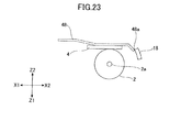
- FIG. 5 and FIG. 6 a retreating (retracting) operation part 700 illustrated in FIG. 5 and FIG. 6 is also described below.
- FIG. 7A is a cross-sectional view of the recorder 100 where the first module 200 and the second module 300 are integrated.
- a roll holding part 202 configured to hold the roll of paper A is formed inside the recorder 100.
- a platen rotating motor (drive source) 204 (hereinafter simply referred to as "motor”) for rotating the platen roller 2 is provided on the upper left of (obliquely upward from) the roll holding part 202.
- the motor 204 is driven to rotate a rotor (not graphically illustrated) supported by a rotor bearing 206.
- the rotation (rotational driving) is transmitted to the platen roller 2 through a gear 208 and a gear 210, so that the platen roller 2 is rotated.
- the integration of the first module 200 and the second module 300 forms the cutting part 40 and causes the platen rotary shaft 2a, which is the rotating shaft of the platen roller 2, to be rotatably supported by a shaft support member 212.
- the platen rotary shaft 2a is rotatably housed inside a bearing member 2c (bearing tube) larger in diameter than the platen rotary shaft 2a. Accordingly, the bearing member 2c is fit to the shaft support member 212, so that the platen rotary shaft 2a is rotatably supported by the shaft support member 212.
- the platen rotary shaft 2a and the bearing member 2c may be omitted for convenience of graphical representation.
- FIG. 7A an end part 212a of the shaft support member 212 is illustrated.
- the end part 212a whose cross section has a U-letter shape or an inverted U-letter shape, includes an air gap (space) 212b ( FIG. 7C ).
- the platen rotary shaft 2a passes through the air gap 212b to be supported by the end part 212a of the shaft support member 212. In the following, this is described as the platen rotary shaft 2a being supported by the shaft support member 212.
- FIG. 7B is a simplified version of FIG. 7A . It is preferable that the shaft support member 212 have the air gap 212b formed (to be open) in a direction toward the upper right in FIG. 7B . This is for the following reasons. First, when a user integrates the first module 200 and the second module 300, the bearing member 2c of the platen roller 2 is caused to fit into the shaft support member 212, pushing up the thermal head 4. Accordingly, it is possible to give a user a feeling of clicking. Further, by directing a bottommost part 212d of the air gap 212b (the shaft support member 212), which has a substantially U-shaped cross section, toward the lower left in FIG. 7B , the bearing member 2c is fixed to the bottommost part 212d, thus being stably fit to the shaft support member 212.
- the air gap 212b the shaft support member 212
- the air gap 212b is formed in the direction toward the upper right. Accordingly, the rotation of the first rotation shaft 302 alone does not cause the bearing member 2c to properly fit to the shaft support member 212 through the air gap 212b. Accordingly, a movable blade block 370 is provided inside the second module 300.
- the movable blade block 370 includes the movable blade 18 and the platen roller 2. As illustrated in FIG. 7C , the movable blade block 370 is configured to rotate (pivot) on a second rotation shaft 304 in a direction away from and in a direction toward (to approach) the first module 200. The distance of this rotation is small. By thus providing the movable blade block 370 inside the second module 300, the bearing member 2c is stably supported by the shaft support member 212. In FIG. 7A , the movable blade block 370 is the upper portion of the second module 300 defined by a broken line a and a one-dot chain line b .
- the platen rotary shaft 2a (the bearing member 2c) is positioned at the bottommost part 212d ( FIG. 7B ) through the air gap 212b ( FIG. 7C ), so that the platen rotary shaft 2a is supported by the shaft support member 212. Further, when the first module 200 and the second module 300 are separated, the platen rotary shaft 2a (the bearing member 2c) positioned at the bottommost part 212d passes through the air gap 212b so that the platen rotary shaft 2a is disengaged from and unsupported by the shaft support member 212.
- FIG. 8 is a perspective view of the movable blade unit 20.
- the second module 300 includes the movable blade unit 20, which is indicated by a broken-line circle X in FIG. 6 .
- the movable unit 20 includes the movable blade 18 and the platen roller 2. As described above, the movable blade 18 is not graphically illustrated in FIG. 6 .
- the movable blade 18 includes a body part 18d and an arm part 18a provided at one end of the body part 18d.
- a through hole 18b for inserting (penetrating) the bearing member 2c of the platen roller 2 is formed in the center portion of the arm part 18a.
- the through hole 18b is slightly larger in diameter than the bearing member 2c. Accordingly, the platen rotary shaft 2a of the platen roller 2 is rotatably supported in the through hole 18b.
- the turning (rotation) of the movable blade 18 does not cause the platen rotary shaft 2a to rotate, nor does the rotation of the platen rotary shaft 2a cause the movable blade 18 to turn (rotate).
- the movable unit 20 further includes a platen gear 2b.
- the platen roller 2 is rotated by the rotation of the platen gear 2b.
- the drive source for the rotation of the platen gear 2b is the motor 204 ( FIG. 7A ).
- the movable blade 18 further includes a second gear 18c provided at the end of the arm part 18a.
- the second gear 18c engages a first gear 220 provided in the first module 200 ( FIG. 6 ).
- the first gear 220 is caused to rotate to transmit a drive force to the second gear 18c, so that the movable blade 18 is caused to turn along the arc ⁇ (for example, FIG. 3 ).
- the recorder 100 of this embodiment includes a drive mechanism 222 for the movable blade 18, and the drive mechanism 222 includes the first gear 220 and the second gear 18c.
- the drive mechanism 222 be formed of only the first gear 220 and the second gear 18c.
- the drive mechanism 222 is provided on one end side of the movable blade 18.
- the drive mechanism 222 is described as including the first gear 220 and the second gear 18c.
- other drive mechanisms may also be employed as long as the other drive mechanisms cause the movable blade 18 to move along the arc ⁇ .
- the movable blade 18 further includes a blade part 18e provided on the body part 18d.
- the blade part 18e forms the edge of the movable blade 18.
- the blade part 18e comes into contact with the paper A to cut the paper A. That is, the blade part 18e (edge) of the movable blade 18 comes into sliding contact with a blade part 6a (edge) of the fixed blade ( FIG. 10 ) to cut the paper A.
- the blade part 6a of the fixed blade 6 and the blade part 18e of the movable blade 18 may be referred to as "first blade part" and "second blade part,” respectively.
- the movable blade 18 further includes a pair of finger parts 18f.
- the finger parts 18f are provided one at each end of the blade part 18e.
- the edge (blade part 18e) of the movable blade 18 has a V-letter shape.
- the movable blade 18 further includes a cut part 18g formed at the center of the blade part 18e, that is, at the bottom of the V-letter shape of the blade part 18e.
- the cut part 18g is provided to perform "partial cutting" on the paper A.
- the "partial cutting” refers to cutting the paper A with part of the paper A left uncut.
- the movable blade 18 or the blade part 18e which is the edge of the movable blade 18 in its moving (traveling) direction, have a cross-sectional shape curving along the arc ⁇ (for example, FIG. 3 ). This ensures stable cutting because the movable blade 18 moves along the arc ⁇ .
- a member curved along the arc ⁇ and having a planar blade may be caused to move along the arc ⁇ . That is, it is satisfactory if the edge of the movable blade 18 (that is, the blade part 18e) is caused to move in an arc.
- FIG. 9A is a schematic plan view of the configuration of FIG. 8 .
- FIG. 9A illustrates the case where the drive mechanism 222 is formed at one end of the movable blade 18.
- FIG. 9B is a schematic plan view of a variation of the configuration of FIG. 8 .
- FIG. 9B illustrates a case where a drive mechanism 222 1 and a drive mechanism 222 2 are provided at a first end and a second end, respectively, of the movable blade 18.
- the drive mechanism 222 1 includes a first gear 220 1 and a second gear 18c 1
- the drive mechanism 222 2 includes a first gear 220 2 and a second gear 18c 2
- the first gear 220 1 and the first gear 220 2 are provided in the first module 200 of the recorder 100.
- FIG. 9A In the case of forming a drive mechanism at one end of the movable blade 18 as illustrated in FIG. 9A , it is possible to reduce the number of components, so that it is possible to reduce the cost of components. On the other hand, in the case of forming a drive mechanism at each end of the movable blade 18 as illustrated in FIG. 9B , it is possible to increase a force for moving the movable blade 18. Accordingly, the configuration of FIG. 9B is effective if the paper A is thick, that is, in the case of cutting thick paper.
- FIG. 10 is a perspective view of the cutter unit 30.
- the cutter of this embodiment may include the cutter unit 30.
- the cutter unit 30 includes the movable blade and the fixed blade 6.
- FIG. 10 graphical illustration of the platen roller 2 is omitted, and the movable blade 18 and the fixed blade 6 are illustrated.
- the fixed blade 6 is a thin plate having a T-letter shape.
- the fixed blade 6 includes the blade part 6a (edge) and a pair of projecting parts 6b.
- the blade part 6a is linear (straight), and the projecting parts 6b are provided one at each end of the blade part 6a to project (extend) outward (in the Y1 and the Y2 direction).
- the finger parts 18f of the movable blade 18 are placed on the upper surfaces of the corresponding projecting parts 6b of the fixed blade 6. This prevents a faulty contact between the movable blade 18 and the fixed blade 6. For example, the movable blade 18 is prevented from sliding under the fixed blade 6. Further, as described above, the blade part 18e of the movable blade 18 has a V-letter shape and the blade part 6a of the fixed blade 6 is linear. Accordingly, an air gap (space) B is formed between the blade part 6a and the blade part 18e. An end portion of the paper A subjected to printing by the printing unit 50 ( FIGS. 2A and 2B ) is caused to project from the air gap B.
- the movable blade 18 moves in the arc ⁇ , so that the sheet A is cut with the movable blade 18 and the fixed blade 6 (or the cutting part 40 illustrated in FIGS. 2A and 2B ). Further, as illustrated in FIG. 10 , the edge (blade part 18e) of the movable blade 18 comes into sliding contact with the edge (blade part 6a) of the fixed blade 6 to move in an arc in a direction J perpendicular to (the longitudinal directions of) the blade part 6a of the fixed blade 6.
- the blade part 18e of the movable blade 18 moves in an arc in the direction J perpendicular to a cross section of the fixed blade 6 taken along a plane parallel to the longitudinal and the thickness directions of the fixed blade 6. That the blade part 18e of the movable blade 18 comes into sliding contact with the blade part 6a of the fixed blade 6 means that the blade part 18e of the movable blade 18 slides on the blade part 6a of the fixed blade 6.
- the blade part 6a of the fixed blade 6 is positioned inside the blade part 18e of the movable blade 18 when the paper A is cut in the cutting part 40. Further, according to the configurations of FIGS. 4B and 4D , the blade part 6a of the fixed blade 6 is positioned outside the blade part 18e of the movable blade 18 when the paper A is cut in the cutting part 40.
- a blade pressure is caused (generated) between the movable blade 18 and the fixed blade 6.
- a blade pressure is generated at the fixed blade in a direction toward the movable blade.
- the platen rotary shaft 2a the bearing member 2c
- the arm part 18a of the movable blade 18 as illustrated in FIG. 8 , the movable blade 18 is prevented from being displaced or caused to deviate without providing a holding member even in the case of a large blade pressure. Accordingly, it is possible to reduce the cost and the size of the cutter.
- the movable blade 18 be moved to a position where the blade part 18e of the movable blade 18 is not exposed outside in the second module 300 when the first module 200 and the second module 300 are separated. This is for the following reason.
- the lid of the recorder 100 is open as described above. If the blade part 18e of the movable blade 18 is exposed outside in this state, this is a problem to the safety of users. Accordingly, when the first module 200 and the second module 300 are separated, the movable blade 18 is moved to a position where the blade part 18e of the movable blade 18 is not exposed outside.
- the position where the blade part 18e of the movable blade 18 is not exposed outside is referred to as the initial position of the movable blade 18.
- the cutting part 40 is formed.
- the formation of the cutting part 40 refers to the placement of the finger parts 18f on the upper surfaces of the corresponding projecting parts 6b with a blade pressure being generated between the movable blade 18 and the fixed blade 6 as illustrated in FIG. 10 .
- forming the cutting part 40 with the movable blade 18 being in the initial position causes the stroke of the movable blade 18 to be longer for the cutting part 40 to enter the post-cutting state ( FIG. 2B ), thus increasing time for cutting the paper A.
- the movable blade 18 may be moved a predetermined amount (distance) in the arc ⁇ from the initial position while ensuring (securing) the air gap B where the paper A is caused to project. This reduces the stroke of the movable blade 18 against the fixed blade 6, thus making it possible to reduce time for cutting the paper A.
- the position to which the movable blade 18 is moved a predetermined amount (distance) (from the initial position) is referred to as "home position.” That is, the home position refers to the position of the movable blade 18 that forms the air gap B where the paper A is caused to project between the movable blade 18 and the fixed blade 6 and minimizes the stroke of the movable blade 18 to cause the cutting part 40 to enter the post-cutting state.
- the state of the cutting part 40 formed with the movable blade 18 in the home position is the above-described pre-cutting state.
- the return part 42 causes the movable blade 18 to return to the home position or the initial position when the blade pressure between the movable blade 18 and the fixed blade 6 is reduced by a predetermined amount.
- a predetermined amount For example, in the case of the recorder 100, when the first module 200 and the second module 300 are separated, the fixed blade 6 and the movable blade 18 are also separated, so that the blade pressure becomes zero. In this case, the movable blade 18 automatically returns (moves) to the initial position with the return part 42.
- a jam (a paper jam at the cutting part 40) may occur in the inseparable recorder (a recorder not divided into the first module 200 and the second module 300) or the recorder 100.
- the blade pressure is reduced by a blade pressure reduction part (not graphically illustrated), which is, for example, a member for pressing down the fixed blade.
- the movable blade 18 may be caused to return to the home position by the return part 42.
- a coil spring may be used for the return part 42 as illustrated in FIG. 10 .
- the coil spring has one end 42a fixed to a predetermined position in the first module 200 (for example, the inner wall of the first module 200) and has another end 42b fixed to the arm part 18a of the movable blade 18.
- a through hole 18i is provided in the arm part 18a, and the end 42b is passed through and fixed to the through hole 18i.
- the return part 42 urges the movable blade 18 in a direction to return the movable blade 18 to the home position or the initial position (in a direction away from the fixed blade 6).
- the drive mechanism 222 causes the movable blade 18 to move to cut the paper A against the urging of the return part 42.
- the blade pressure is reduced by the blade pressure reduction part.
- the movable blade 18 is caused to return to the home position by the urging of the return part 42, thereby escaping from the jam.
- the return part 42 urges the movable blade 18 to return the movable blade 18 to the initial position.
- the drive mechanism 222 causes the movable blade 18 to move against the urging of the return part 42.
- the blade pressure between the movable blade 18 and the fixed blade 6 becomes zero. Accordingly, the movable blade 18 is caused to return to the initial position by the urging of the return part 42.
- FIG. 11 illustrates a variation of the movable blade 18.
- a movable blade 19 may be mounted on a mounting base 32.
- the movable blade 19 is detachably fixed to the mounting base 32 with the screws 32c.
- the mounting base 32 includes a pair of arm parts 32d one at each end of the mounting base 32. The arm parts 32d are equal in shape to the arm parts 18a illustrated in FIG. 8 . Accordingly, the mounting base 32 with the movable blade 19 attached has substantially the same shape as the movable blade 18 illustrated in FIG. 8 .
- the mounting base 32 may have an arc shape along the arc ⁇ with the movable blade 19 having either a flat shape or an arc shape along the arc ⁇ .
- FIG. 12 is a perspective view of a movable blade 18', which is another variation of the movable blade 18.
- the movable blade 18 illustrated in FIG. 8 has a V-shaped edge, while a blade part (edge) 18e' of the movable blade 18' is inclined in a widthwise direction indicated by arrow Q (in the Y2 direction).
- An air gap (not graphically illustrated) is also formed between the fixed blade 6 and the movable blade 18'. Accordingly, it is possible to stably cut the paper A with this movable blade 18' as well.
- FIG. 13 illustrates another variation of the movable blade 18.
- the blade part (edge) 18e of the movable blade 18 has a width indicated by double-headed arrow L greater than the width (or a dimension in the longitudinal directions of the platen rotary shaft 2a) of the paper A ( FIG. 6 ).
- This shape of the movable blade 18 makes it possible to cut the paper A completely to its sides in the widthwise directions (the Y1 and the Y2 direction).
- the movable blade 18 includes a base part 18x and a wide part 18y wider than the base part 18x.
- the blade part 18e is formed at the end of the wide part 18y.
- the movable blade 18 illustrated in FIG. 13 has a substantial T-letter shape in a plan view.
- a blade pressure generation part generates a blade pressure between the movable blade 18 and the fixed blade 6.
- the blade pressure generated at the fixed blade 6 in the direction toward the movable blade 18 by the blade pressure generation part is referred to as "fixed-blade blade pressure.”
- the blade pressure generated at the movable blade 18 in the direction toward the fixed blade 6 by the blade pressure generation part is referred to as "movable-blade blade pressure.” That is, the blade pressure generation part generates at least one of the movable-blade blade pressure and the fixed-blade blade pressure.
- FIG. 14 is a perspective view of a configuration including the cutter unit 30 and the platen roller 2.
- a fixed blade spring 62 is provided as the blade pressure generation part.
- the fixed blade spring 62 includes a pair of finger parts 62a and a base part 62b.
- the finger parts 62b are provided one at each end of the base part 62b.
- the finger parts 62a are in contact with the fixed blade 6 to urge the fixed blade 6 in the direction toward the movable blade 18.
- a blade pressure is generated between the movable blade 18 and the fixed blade 6 by the fixed blade spring 62 urging the fixed blade 6 toward the movable blade 18. That is, the fixed blade spring 62 (the blade pressure generation part) generates the fixed-blade blade pressure.
- the fixed blade spring 62 is held by a spring holding member 64.
- the base part 62b of the fixed blade spring 62 is held by the spring holding member 64.
- multiple screw holes 66 may be formed in the base part 62b so that the base part 62b is held by the spring holding member 64 with screws inserted into the screw holes 66.
- the spring holding member 64 includes multiple (for example, two) through holes 64a.
- the spring holding member 64 is attached to a support member 70 ( FIG. 16 ) such as the inner wall of the first module 200.
- the fixed blade spring 62 may be held by, for example, the inner wall of the first module 200 instead of being held by the spring holding member 64.
- FIG. 15 is a perspective view of the configuration of FIG. 14 , taken from a different angle.
- the movable blade 18 is supported by a movable blade support plate 182 so as to prevent its displacement or deviation.
- FIG. 15 illustrates a case where the first gears 220 1 and 220 2 are provided (that is, the drive mechanisms 222 1 and 222 2 [ FIG. 9B ] are provided) one at each longitudinal end of the movable blade 18.
- the first gears 220 1 and 220 2 are connected by a gear shaft 223.
- a graphical representation of the teeth of the first gears 220 1 and 220 2 and the second gears 18c 1 and 18c 2 is omitted.
- FIG. 16 is a schematic plan view of the configuration illustrated in FIG. 14 and FIG. 15 .
- a graphical representation of the spring holding member 64 is omitted in FIG. 16 .
- one end of the fixed blade spring 62 (the finger parts 62a) is in press contact with the fixed blade 6.
- the other end of the fixed blade spring 62 (the base part 62b), that is, the spring holding member 64, is attached to the support member 70.
- the fixed-blade blade pressure is to be increased in order to increase the cutting force of the cutting part 40, it is necessary to increase the elastic force of the fixed blade spring 62.
- it is necessary to increase the thickness of the support member 70 which results in an increase in the size of the cutter.
- the fixed blade spring 620 as a whole has elasticity, and is used as the blade pressure generation part that generates the fixed-blade blade pressure.
- FIG. 17 and FIG. 18 are a side view and a perspective view, respectively, of the fixed blade spring 620.
- a pair of (two) narrow fixed blade springs 620 are attached one to each end of the bearing member 2c.
- FIG. 17 and FIG. 18 only one end of the bearing member 2c is illustrated, but the narrow fixed blade spring 620 is also attached to the other end of the bearing member 2c.
- the fixed blade spring 620 has a flat part 620a at one end and a curved part 620c at the other end.
- the fixed blade spring 620 includes a bent part 620b between the flat part 620a and the curved part 620c.
- the fixed blade 6 is placed on the flat part 620a.
- the curved part 620c is curved along the bearing member 2c so as to be in contact with the bearing member 2c, which serves as the support member 70.
- the fixed blade 6 is placed on the flat parts 620a of the two fixed blade springs 620.
- the U-shaped shaft support member 212 and the fixed blade spring 620 are disposed in this order from the platen roller 2 side.
- the shaft support member 212 is formed with such rigidity as to sustain a pressure from the thermal head 4. Accordingly, increasing the resilience of the fixed blade spring 620 to increase the fixed-blade blade pressure does not necessitate an increase in the thickness of the shaft support member 212. Accordingly, increasing the fixed-blade blade pressure does not necessitate an increase in the thickness of the support member 70. That is, the bearing member 2c and the movable blade 18 mounted on the bearing member 2c ( FIG. 8 ) cancel out an urging force F 1 ( FIG. 17 ) to urge the fixed blade 6 toward the movable blade 18 side and a pressing force F 2 ( FIG. 17 ) (a repulsive force) to press the platen rotary shaft 2a.
- the elasticity of the fixed blade spring 620 allows the bearing member 2c to push aside the curved part 620c to fit into the shaft support member 212.
- the fixed blade spring 620 further serves to hold the bearing member 2c to the bottommost part 212d ( FIG. 7B ). This pressing by the fixed blade spring 620 prevents the bearing member 2c from coming easily off the bottommost part 212d of the shaft support member 212.
- the platen rotary shaft 2a it is preferable to cause the platen rotary shaft 2a to pass through the center O of the arc ⁇ (the circle P) ( FIG. 3 ) using the fixed blade spring 620 because this facilitates the positioning of the movable blade 18 and the fixed blade 6.
- FIG. 19 is a perspective view of an arrangement for causing the movable-blade blade pressure to be generated at the movable blade 18.
- the mounting base 32 FIG. 11
- the movable blade pressurizing springs 32b have elasticity.
- the movable blade 18 is attached and fixed to the end portions of the two movable blade pressurizing springs 32b.
- the movable blade 18 is fixed to the two movable blade pressurizing springs 32b with the screws 32c.
- the movable blade pressurizing springs 32b urge the movable blade 18 in the direction toward the fixed blade 6, so that it is possible to generate the movable-blade blade pressure.
- both the movable-blade blade pressure and the fixed-blade blade pressure may be generated. In this case, it is possible to increase the blade pressure, so that it is possible to cut thick paper.
- FIG. 20 is a perspective view of the printing unit 50.
- FIG. 21 is a schematic side view of the printing unit 50.
- the printing unit 50 includes the platen roller 2 and the thermal head 4 as schematically illustrated in FIGS. 2A and 2B .
- FIG. 20 a graphical representation of the fixed blade 6 and the movable blade 18 is omitted.
- the thermal head 4 is held by a head holding member 43.
- the head holding member 43 has a flat plate shape, and has projecting parts 43a formed one at each of its longitudinal (Y1 and Y2) ends to project (extend) outward. Further, the head holding member 43 also serves as a heat sink (a heat radiation member) to radiate heat from the thermal head 4. Further, the projecting parts 43a engage corresponding recesses (not graphically illustrated) in the first module 200 so that the head holding member 43 to which the thermal head 4 is attached is held.
- a head pressurizing spring 44 is attached on a side of the head holding member 43 which side is opposite to the side on which the thermal head 4 is attached.
- the head pressurizing spring 44 urges the thermal head 4 against the platen roller 2 through the head holding member 43, thereby causing the thermal head 4 to be in press contact with the platen roller 2.
- This press contact force is determined to be such a value as to allow the platen roller 2 to rotate.
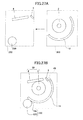
- FIG. 22 is a diagram illustrating a variation of the arrangement (configuration) illustrated in FIG. 21 .
- the number of components is reduced compared with the arrangement of FIG. 21 .
- the fixed blade 6 and the head holding member 43 are provided separately.
- an end portion 46a of a head holding member 46 is turned into the fixed blade 6. That is, the head holding member 46 integrates the function of the head holding member 43 and the function of the fixed blade 6. This configuration makes it possible to reduce the number of components compared with the case illustrated in FIG. 21 .
- FIG. 23 is a diagram illustrating a variation of the arrangement (configuration) illustrated in FIG. 21 .
- the thermal head 4 is held by a head holding elastic member 48.
- the head holding member 48 has elasticity, which causes the thermal head 4 to be in press contact with the platen roller 2.
- the head holding elastic member 48 has an end portion 48a serve as the fixed blade 6. That is, the head holding elastic member 48 integrates the functions of the head pressurizing spring 44, the head holding member 43, and the fixed blade 6 illustrated in FIG. 21 .
- Using this head holding elastic member 48 makes it possible to reduce the number of components compared with the case of FIG. 22 .
- FIG. 24 is a perspective view of an arrangement including the printing unit 50 of FIG. 20 .
- FIG. 25 is a perspective view of the arrangement of FIG. 24 with the paper A in a rolled-up state placed below the platen roller 2, taken from the same angle as FIG. 24 .
- the head pressurizing spring 44 is fixed to the head holding member 43 or a support member (not graphically illustrated) of the first module 200 with screws 44a passed through two screw holes in the head pressurizing spring 44.
- a flexible plate 4a for transmitting printing information to the thermal head 4 ( FIG. 20 ) is attached to the rear of the thermal head 4.
- the motor 204 ( FIG. 7A ) is provided on the platen gear 2b (X1) side on the rear side of the thermal head 4.
- a gear housing part 252 is provided on the platen gear 2b side of the thermal head 4 in its longitudinal directions (the X1 and the X2 direction).
- the gears 208 and 210 ( FIG. 7A ) are provided in the gear housing part 252.
- the gears 208 and 210 may be replaced with a timing belt.
- the shaft support member 212 is provided on the side of the thermal head 4 opposite to the platen gear 2b side in its longitudinal directions. As illustrated with reference to FIG. 7A , the platen rotary shaft 2a is rotatably supported by the end part 212a of the shaft support member 212.
- FIG. 26 is a perspective view of the printer unit 400.
- the printer unit 400 integrates the printing unit 50 (for example, FIG. 20 ) and the cutter unit 30 (for example, FIG. 10 ).
- the spring holding member 64 of the cutting part 40 is placed so that the lower surface of the spring holding member 64 is in contact with the upper surface of the head pressurizing spring 44 of the printing unit 50.
- the drive mechanism 222 and a cutter drive motor 224 for driving the drive mechanism are placed on the side of the printer unit 400 opposite to the gear housing part 252 in its longitudinal directions (the X1 and the X2 direction).
- FIGS. 27A and 27B illustrate a process of formation of the printer unit 400 in a simplified manner.
- a graphical representation of the teeth of the first gear 220 and the second gear 18c ( FIG. 10 ) is omitted.
- the first module 200 and the second module 300 are integrated to form the printing unit 50, the cutting part 40, and the drive mechanism 222.
- the lock part 60 prevents the first module 100 and the second module 200 from being separated unless a user releases the lock set by the lock part 60 when the first module 200 and the second module 300 are integrated.
- FIG. 28 and FIG. 29 are a schematic side view and a perspective view, respectively, of an arrangement including the lock part 60. Further, FIGS. 30A and 30B illustrate a locking process of the lock part 60. FIG. 28 illustrates a state immediately before the lock part 60 performs locking.
- the first module 200 includes a fixed blade block 250.
- the fixed blade block 250 includes a pair of (two) thin-plate arm members 280, a second rotation shaft 252, and the fixed blade 6.
- Each of the arm members 280 includes a cut 280a.
- the fixed blade 6 has its projecting parts 6b engaging the corresponding cuts 280a, so that the fixed blade 6 is placed across the gap between the arm members 280.
- the fixed blade spring 62 ( FIG. 14 ) is provided as the blade pressure generation part.
- the second rotation shaft 252 is provided at first ends of the arm members 280, and lock claws 256 are provided at second ends of the arm members 280.
- the fixed blade block 250 is rotatable (pivotable) in a direction toward (to approach) the second module 300 and in a direction away from the second module 300 on the second rotation shaft 252.
- the fixed blade block 250 is urged in the direction toward the second module 300 (in the Z1 direction) by an elastic member 254 such as a spring.
- the above-described first rotation shaft 302 (for example, FIG. 7A ) is provided at one end of the second module 300, and a lock shaft 350 is provided at the other end of the second module 300.
- Each of the lock claws 256 includes a curved guide part (surface) 256a on the side facing the lock shaft 350 and an engagement part 256b to engage the lock shaft 350 on the other side (the side opposite to the guide part 256a).
- the lock shaft 350 is guided by the guide parts 256a (that is, slides on the curves of the guide parts 256a) to push the fixed blade block 250 upward (in the Z2 direction) against the urging of the elastic member 254, so that the elastic member 254 is bent.
- the lock shaft 350 engages the engagement parts 256b so that the fixed blade block 250 is caused to move downward (in the Z1 direction) by the urging of the elastic member 254 as illustrated in FIG. 31 .
- the first module 200 and the second module 300 are integrated and locked by the lock shaft 350 engaging the lock claws 256 (the engagement parts 256b).
- the platen rotary shaft 2a is supported by the shaft support member 212, and a blade pressure is generated between the movable blade 18 and the fixed blade 6 by the blade pressure generation part, which is the fixed blade spring 62 in the illustrated case.
- the engagement parts 256b are disengaged from the lock shaft 350 because of a blade pressure between the fixed blade 6 and the movable blade 18. Then, the lock shaft 350 is caused to move in the direction away from the fixed blade block 250 (in the X2 direction). This movement of the lock shaft 350 releases the lock set by the lock part 60. Further, the blade pressure between the fixed blade 6 and the movable blade 18 causes the platen rotary shaft 2a to pass the air gap 212b of the shaft support member 212 to be unsupported by the shaft support member 212.
- the blade pressure causes the second module 300 to turn in the direction away from the first module 200, so that the first module 200 and the second module 300 are separated.
- a press button may be provided as a lock release (unlocking) part to cause the fixed blade block 250 to turn (rotate) in the direction away from the second module 300.
- the fixed blade block 250 may be turned in the direction away from the second module 300 by pressing this press button. Further, the fixed blade block 250 may be turned in the direction away from the second module 300 by a user's direct operation (for example, pressing) of a predetermined part of the first module 200.
- the first module 200 and the second module 300 are automatically separated (because of a blade pressure between the movable blade 18 and the fixed blade 6) in response to the release of a lock by a user, thus increasing convenience.
- FIG. 31 illustrates a variation of the arrangement illustrated in, for example, FIG. 28 .
- the fixed blade block 250 is urged by the elastic member 254.
- the fixed blade springs 620 FIG. 17 may be employed as the blade pressure generation part. In this case, it is possible to omit the elastic member 254.
- an end returning part 640 is employed. It is preferable to use the end returning part 640 in configurations where the blade part (edge) 6a of the fixed blade 6 is positioned outside the blade part (edge) 18e of the movable blade 18 when cutting the paper A in the cutting part 40 ( FIGS. 4B and 4D ).
- FIG. 32 and FIG. 33 are a schematic side view and a perspective view, respectively, of an arrangement including the end returning part 640.
- the end returning part 640 returns an end A1 of the paper A conveyed by the movable blade 18 to a position where cutting is performable by the cutting part 40 (a position where the end A1 projects from the air gap B). This position is hereinafter referred to as "cutting performable position.”
- the end A1 of the paper A (the end of the remaining portion of the paper A after a portion of the paper A is cut) is conveyed by an end part 18p (the blade part 18e) of the movable blade 18, formed by the thickness of the movable blade 18, so that the end A1 is not at the cutting performable position. Then, the end A1 collides with the fixed blade 6, thus resulting in the occurrence of a jam. As a result, the cutting part 40 is prevented from performing cutting properly in the next cutting. By returning the end A1 to the cutting performable position with the end returning part 640, it is possible to perform cutting in the next cutting as well. In the case illustrated in FIG.
- the end returning part 640 is formed of an elastic member such as a spring.
- the end returning part 640 includes multiple (for example, three) tongue piece parts 640a.
- the end returning part 640 further includes upward warping parts 640b provided at the respective ends of the tongue piece parts 640a.
- the end returning part 640 may be attached on the fixed blade block 250. In the case illustrated in FIG. 33 , the end returning part 640 is fixed to the upper side of the fixed blade block 250 ( FIG. 29 ) with screws 640c.
- the end 18p of the movable blade 18 is in contact with or almost in contact with the upward warping parts 640b.
- the end 18p of the movable blade 18 conveys the end A1 of the paper A
- the conveyed end A1 collides with the upward warping parts 640b.
- the movable blade 18 returns to the home position after cutting the paper A.
- the end A1 that has collided is moved (flipped) in the direction opposite to the conveying direction by the elastic force of the end returning part 640 so as to be at the cutting performable position.
- this retreating operation part 700 ( FIG. 6 ). It is preferable to provide this retreating operation part 700 in configurations where the blade part (edge) 6a of the fixed blade 6 is positioned on the downstream side in the direction in which the paper A is discharged (that is, outside the blade part [edge] 18e of the movable blade 18) ( FIGS. 4B and 4D ).
- FIG. 34 is a diagram for illustrating the retreating operation part 700.
- FIG. 34 is substantially equal to FIG. 4B , but schematically illustrates one of the finger parts 18f (for example, FIG. 8 ) of the movable blade 18. That is, in FIG. 34 , the finger parts 18f and the projecting parts 6b (for example, FIG. 10 ) of the fixed blade 6 are in contact.
- the path of the movable blade 18 at the time of separating the second module 300 from the first module 200 is indicated by arrow C and is referred to as a separation path C.
- the movable blade 18 is blocked by the fixed blade 6 to prevent the second module 300 from being turned (rotated) because the finger parts 18f and the projecting parts 6b are in contact.
- the retreating operation part 700 is provided on an exterior side of the recorder 100 as illustrated in FIG. 5 .
- the retreating operation part 700 is operated at the time of separating the first module 200 and the second module 300, the fixed blade 6 is retracted to a position where the fixed blade 6 is prevented from contacting the movable blade 18. That is, the fixed blade 6 is retracted outside the separation path C.
- the retreating operation part 700 may be, for example, a push-down lever.
- the fixed blade 6 may be retracted, for example, in the Z2 direction (the direction away from the movable blade 18, which is the upward direction in the plane of the paper of FIG. 34 ) in conjunction with a user's pushing down the push-down lever.
- This retreat (retraction) makes it possible to cause the second module 300 to turn in the direction away from the first module 200 without the fixed blade 6 blocking the movable blade 18.
- the direction of the retreat is not limited to the Z2 direction, and may be any other direction as long as the fixed blade 6 is retracted outside the separation path C.
- retreating operation part 700 and the above-described lock release part may be integrated into a retreating operation and lock release part, which may be in the form of a push-down lever.
- a retreating operation and lock release part which may be in the form of a push-down lever.
- a cutting blade sensor that senses (detects) the status of a cutting blade
- a platen sensor that senses (detects) the fitting of a platen roller to a shaft (the support of a platen roller by a shaft) (the integration or separation of a first module and a second module)
- a paper sensor that senses (detects) the presence or absence of (a sheet of) paper are provided as separate bodies.
- the sensors may be, for example, switches or photosensors (photodetectors). According to this configuration, three sensors are necessary, which causes an increase in cost and an increase in apparatus size.
- the detection part 510 serves as a cutting blade sensor and a platen sensor.
- FIG. 35 is a diagram illustrating a functional configuration of a control part 500, to which the detection part 510 is connected.
- the control part 500 includes a motor drive part 502, an operation part 504, a recognition part 506, and a transmission part 508.
- the recognition part 506 recognizes (determines) the integration or separation of the first module 200 and the second module 300 (the support [fitting] of the platen roller 2 by [to] the shaft support member 212 or the disengagement of the platen roller 2 [the platen rotary shaft 2a] from the shaft support member 212), the presence or absence of the movable blade 18 (a movable blade detection process determining the presence or absence of the movable blade 18), and the presence or absence of cutting by the cutting part 40 (a cutting detection process determining the presence or absence of cutting by the cutting part 40).
- a photosensor or a switch may be used as the detection part 510.
- the detection part 510 is a photosensor.
- the motor drive part 502 drives the motor 204 ( FIG. 7A ), thereby rotating the platen roller 2.
- the operation part 504 drives the drive mechanism 222, thereby moving the movable blade 18 in the arc ⁇ .
- FIGS. 36A, 36B, and 36C are diagrams for illustrating a detecting operation performed by the detection part 510.
- the movable blade 18 includes a block part 18q.
- the block part 18q is illustrated in a simplified manner.
- the block part 18q may be provided on the rear (the side opposite to the blade part 18e) of the body part 18d of the movable blade 18. That is, the block part 18q may be provided at an end of the movable blade 18 opposite to the end at which the blade part 18e is provided.
- the detection part 510 includes an emission part 510a to emit light and an entrance part 510b ( FIG. 36C ) which the emitted light enters (a reception part to receive the emitted light).
- the entrance part 510b may be provided across a space (into which the block part 18q is allowed) from the emission part 510a.
- the region between the initial position (indicated by a one-dot chain line in FIG. 36B ) and the home position (indicated by a solid line in FIG. 36B ) of the movable blade 18 may be referred to as "a detection region D."
- the block part 18q blocks light as illustrated in FIG. 36B .
- the detection region D also includes the initial position and the home position of the movable blade 18.
- the light block part 18q does not block light emitted from the emission part 510a. Accordingly, the entrance part 510b receives the emitted light, so that the detection part 510 detects the absence of the movable blade 18 in the detection region and determines that the movable blade 18 is not in the detection region.
- the block part 18q blocks light emitted from the emission part 510a. Accordingly, the detection part 510 detects the presence of the movable blade 18 in the detection region D and determines that the movable blade 18 is in the detection region D.
- the detection part 510 transmits information indicating the presence (detected state) or absence (undetected state) of the movable blade 18 to the recognition part 506.
- the recognition part 506 recognizes (determines) various states from the transmitted detection information.
- the detected state of the movable blade 18 is referred to as “an OFF state” and the undetected state of the movable blade 18 is referred to as "an ON state.”
- FIGS. 37A and 37B are timing charts of an operation according to this embodiment.
- FIGS. 38A and 38B are flowcharts for illustrating the operation according to this embodiment.
- the amount of driving includes a first amount of driving, a second amount of driving, a third amount of driving, and a fourth amount of driving.
- the amount of driving refers to the amount of rotation (the rotation [turning] angle) of the first gear 220 if the drive mechanism 222 is formed of the first gear 220 and the second gear 18c.
- (d) indicates the amount of movement (traveling) of the movable blade 18, which includes a first predetermined amount and a second predetermined amount in this case)
- (e) indicates the positional relationship between the movable blade 18 and the detection part 510 with miniature versions of FIGS. 36A and 36B (in which the block part 18q is indicated by hatching)
- (f) indicates the state recognized by the recognition part 506, and (g) indicates a time axis.
- State M1 the first module 200 and the second module 300 are separated, so that the movable blade 18 is not in the detection region D ( FIG. 36B ). Therefore, in step S2 of FIG. 38A , the detection part 510 detects an ON state (hereinafter, a first ON state). Then, in step S4 of FIG. 38A , the recognition part 506 recognizes (determines) the separation (separated state) of the first module 200 and the second module 300.
- a first ON state hereinafter, a first ON state
- the recognition part 506 recognizes (determines) the separation (separated state) of the first module 200 and the second module 300.
- State M2 the first module 200 and the second module 300 are integrated.
- the movable blade 18 is in the detection region D, being first positioned at the initial position and then moved to the home position. Accordingly, the detection part 510 detects an OFF state (hereinafter, a first OFF state) (YES in step S6 of FIG. 38A ). Then, in step S8, the recognition part 506 recognizes (determines) the integration of the first module 200 and the second module 300.
- a first OFF state hereinafter, a first OFF state
- the operation part 504 does not cause the drive mechanism 222 to be driven. That is, when the operation part 504 does not cause the drive mechanism 222 to be driven, the detection part 510 detects the absence of the movable blade 18 in the detection region D (step S4, State M1), and thereafter, the detection part 510 detects the presence of the movable blade 18 in the detection region D (YES in step S6, State M2), the recognition part 506 recognizes the integration of the first module 200 and the second module 300 (step S8). If the detection part 510 does not detect the first OFF state (NO in step S6), the operation returns to step S6.
- control part 500 performs a movable blade detection process V 1 (steps S10 through S18 of FIG. 38A and States M3 through M6 of FIG. 37A ), where the presence or absence of the movable blade 18 is detected and it is determined whether the movable blade 18 moves normally.
- step S10 of FIG. 38A the operation part 504 causes the drive mechanism 222 to be driven by the first amount of driving (State M3).
- the operations part 504 is in the middle of causing the drive mechanism 222 to be driven by the first amount of driving (to move the movable blade 18).
- the movable blade 18 moves in the arc ⁇ from the home position by the first predetermined amount (State M4).
- the movable blade 18 has moved the first predetermined amount (the movable blade 18 has finished moving the first predetermined amount).
- the detection part 510 detects an ON state (hereinafter, a second ON state) (YES in step S12, State M4), and the operation proceeds to step S14.
- a second ON state hereinafter, a second ON state
- step S14 the operation part 504 causes the drive mechanism 222 to be driven by the second amount of driving (State M5).
- the operation part 504 is in the middle of causing the drive mechanism 222 to be driven by the second amount of driving.
- the movable blade 18 returns the first predetermined amount from its position after the (previous) movement of the first predetermined amount to move (return) to the home position (State M6).
- the movable blade 18 has moved the first predetermined amount (the movable blade 18 has returned to the home position).
- Driving by the second amount of driving means causing the first gear 220 to rotate in the reverse direction compared with driving by the first amount of driving.
- the detection part 510 detects an OFF state (hereinafter, a second OFF state) (YES in step S16, State M6), and the operation proceeds to step S18.
- a second OFF state hereinafter, a second OFF state
- the recognition part 506 recognizes (determines) the presence of the movable blade 18 in the detection region D.
- the operation part 504 causes the drive mechanism 222 to be driven by the first amount of driving so that the detection part 510 detects the absence of the movable blade 18 in the detection region D (steps S10 and S12, States M3 and M4), and the operation part 504 causes the drive mechanism 222 to be driven by the second amount of driving after driving by the first amount of driving so that the detection part 510 detects the presence of the movable blade 18 in the detection region D (steps S14 and S16, States M5 and M6), the recognition part 506 recognizes (determines) the presence of the movable blade 18 in the detection region D and that the movable blade 18 moves normally.
- the cutter After completion of the movable blade detection process V 1 , the cutter is in a standby state until the printing unit 50 finishes printing on the paper A and a CUT command is transmitted from the control part 500 to the cutter (State M7, step S19). In response to transmission of a CUT command from the control part 500 to the cutter (YES in step S19), the operation proceeds to the subsequent cutting detection process V 2 .
- the cutting process is a process for performing an operation necessary for the paper A to be cut by the cutting part 40. That is, the cutting process is a process where the movable blade 18 moves from its position (home position) in the pre-cutting state of the cutting part 40 to its position (post-movable-blade-cutting position) in the post-cutting state of the cutting part 40, and then returns to the home position. If the cutting process ends properly when the paper A is in the cutting performable position, the paper A is cut.
- step S20 of FIG. 38B the operation part 504 causes the drive mechanism 222 to be driven by the third amount of driving (State M7).
- state M7 the operation part 504 is in the middle of causing the drive mechanism 222 to be driven by the third amount of driving.
- the movable blade 18 moves the second predetermined amount from the home position along the arc ⁇ to the post-movable-blade-cutting position (State M8).
- State M8 the movable blade 18 has moved the second predetermined amount along the arc ⁇ (the movable blade 18 is at the post-movable-blade-cutting position).
- the second predetermined amount is when the cutting part 40 enters the post-cutting state, that is, when the cutting part 40 cuts the paper A if the paper A is in the cutting performable position.
- the detection part 510 detects an ON state (hereinafter, a third ON state) (YES in step S22), and the operation proceeds to step S24.
- a third ON state hereinafter, a third ON state
- step S24 the operation part 504 causes the drive mechanism 222 to be driven by the fourth amount of driving (State M9).
- the operation part 504 is in the middle of causing the drive mechanism 222 to be driven by the fourth amount of driving.
- the movable blade 18 returns the second predetermined amount from its position after the (previous) movement of the second predetermined amount to move (return) to the home position (State M10).
- the movable blade 18 has moved (returned) to the home position.
- Driving by the fourth amount of driving means causing the first gear 220 to rotate in the reverse direction compared with driving by the third amount of driving.
- the detection part 510 detects an OFF state (hereinafter, a third OFF state) (YES in step S26), and the operation proceeds to step S28.
- a third OFF state hereinafter, a third OFF state
- the cutting process refers to a process where the operation part 504 causes driving by the third amount of driving to move the movable blade 18 by the second predetermined amount (to move the movable blade 18 to the post-movable-blade-cutting position), and thereafter, causes driving by the fourth amount of driving to return the movable blade 18 by the second predetermined mount (to place the movable blade 18 at the home position).
- step S28 the recognition part 506 recognizes the completion of the cutting process of the cutting part 40. That is, when the recognition part 506 recognizes the presence of the movable blade 18 (step S18, State M8), the operation part 504 causes the drive mechanism 222 to be driven by the third amount of driving so that the detection part 510 detects the absence of the movable blade 18 in the detection region D (YES in step S22, State M8), and the operation part 504 causes the drive mechanism 222 to be driven by the fourth amount of driving after driving by the third amount of driving so that the detection part 510 detects the presence of the movable blade 18 in the detection region D (YES in step S26, State M10), in step S28, the recognition part 506 recognizes the completion of the cutting process of the cutting part 40.
- step S30 if it is determined in step S30 that there is another printing and cutting operation to follow (NO in step S30), the operation returns to step S20. If there is no subsequent printing or cutting (YES in step S30), the operation ends.
- the separation detection process may be a process for determining whether the platen roller 2 has moved.
- the recognition part 506 recognizes (determines) the separation of the first module 200 and the second module 300.
- the movable blade 28 is in State M2
- the standby state after State M6 and the standby state after State M10 ( FIGS. 37A and 37B ) that the operation part 504 is not driving the drive mechanism 222. That is, "when the operation part 504 is not driving the drive mechanism 222" refers to the states other than the state of performing the movable blade detection process V 1 (States M3 through M6) and the state of performing the cutting detection process V 2 .
- the detection part 510 is in a standby state, detecting the presence (positioning) of the movable blade 18 in the detection region D unless the movable blade detection process V 1 or the cutting detection process V 2 is performed. (See (e) of State M2 and Standby State in FIGS. 37A and 37B .) However, if the detection part 510 detects the absence of the movable blade 18 in the detection region D in this state (that is, when the operation part 504 is not driving the drive mechanism 222), this means that the first module 200 and the second module 300 are separated so that the movable blade 18 is not positioned in the detection region D.
- the recognition part 506 recognizes (determines) the separation of the first module 200 and the second module 300.
- the detection part 510 asynchronously detects or cannot detect a state (ON state or OFF state) in response to the driving of a predetermined amount of driving (each of the first through fourth amount of driving) by the operation part 504, the recognition part 506 recognizes a malfunction of the movable blade 18.
- the recognition part 506 recognizes a malfunction of the movable blade 18.
- the malfunction of the movable blade 18 include the inability of the movable blade 18 to move properly due to improper formation of the drive mechanism 222.
- the recognition part 506 recognizes a malfunction of the movable blade 18. This is because the movable blade 18 is not supposed to be positioned in the detection region D and the detection part 510 is supposed to detect an ON state after the operation part 504 causes the drive mechanism 222 to be driven by the first amount of driving.
- the detection part 510 does not detect an OFF state (the second OFF state) (that is, if the detection part 510 detects an ON state) in response to the driving of the drive mechanism 222 by the second amount of driving by the operation part 504 (NO in step S16 of FIG. 38A ), if the detection part 510 does not detect an ON state (the third ON state) (that is, if the detection part 510 detects an OFF state) in response to the driving of the drive mechanism 222 by the third amount of driving by the operation part 504 (NO in step S22 of FIG.
- the transmission part 508 ( FIG. 35 ) transmits error information.
- the recognition part 506 recognizes a malfunction of the movable blade 18.
- the transmission part 508 may be configured to transmit error information in response to the recognition part 506 recognizing a malfunction of the movable blade 18.
- a display part may be provided on the exterior of the recorder 100 ( FIG. 5 ), and the transmitted error information may be displayed on the display part.
- the display part is an error lamp, the error lamp may be turned on.
- the first amount of driving and the third amount of driving may be equalized, and the second amount of driving and the fourth amount of driving may be equalized. This makes it possible to simplify the configuration of the operation part 504. In this case, the first predetermined amount and the second predetermined amount are equal.
- providing the detection part 510 and the recognition part 506 makes it possible to recognize (determine) the state of a cutting blade (the movable blade 18) and the state of the fitting (the shaft-supported state) of the platen roller 2 (the integration or separation of the first module 200 and the second module 300). Accordingly, it is possible to recognize (determine) the remaining amount of the paper A, the state of a cutting blade, and the state of the fitting (the shaft-supported state) of the platen roller 2 (the integration or separation of the first module 200 and the second module 300) with two sensors, that is, a paper sensor and the detection part 510. Accordingly, it is possible to reduce the cost and the size of the cutter and the recorder.
- the recognition part 506 and the detection part 510 may recognize (determine) the completion of the cutting process and a malfunction of the movable blade 18.
- Embodiments of the invention extend to a cutter, characterized by a cutting part including a movable blade and a fixed blade, the movable blade being configured to be moved by a drive mechanism; an operation part configured to cause an edge of the movable blade to move in an arc by causing the drive mechanism to be driven; and a blade pressure generation part configured to cause a blade pressure to be generated between the movable blade and the fixed blade.
- the cutter may be further characterized by a first module including the fixed blade; and a second module including the movable blade, the second module being configured to rotate on a first rotation shaft to be integrated with and separated from the first module, wherein the first module and the second module are configured to be integrated to form the cutting part.
- the cutter may be further characterized by a detection part configured to detect a presence or absence of the movable blade in a detection region; and a recognition part configured to recognize an integration of the first module and the second module if there is an absence of a driving of the drive mechanism caused by the operation part and the detection part detects the presence of the movable blade in the detection region after detecting the absence of the movable blade in the detection region.
- the cutter may be further, characterized in that the recognition part is configured to recognize a presence of the movable blade if the recognition part recognizes the integration of the first module and the second module; the operation part causes the drive mechanism to be driven by a first amount of driving, so that the detection part detects the absence of the movable blade in the detection region; and the operation part causes the drive mechanism to be driven by a second amount of driving after the driving of the drive mechanism by the first amount of driving, so that the detection part detects the presence of the movable blade in the detection region.
- the cutter may be further characterized in that the recognition part is configured to recognize a completion of a cutting process of the cutting part if the recognition part recognizes the presence of the movable blade; the operation part causes the drive mechanism to be driven by a third amount of driving, so that the detection part detects the absence of the movable blade in the detection region; and the operation part causes the drive mechanism to be driven by a fourth amount of driving after the driving of the drive mechanism by the third amount of driving, so that the detection part detects the presence of the movable blade in the detection region.
- the cutter may be further characterized in that the recognition part is configured to recognize a malfunction of the movable blade if the detection part detects the presence of the movable blade in the detection region in response to the operation part causing the drive mechanism to be driven by one of the first amount of driving and the second amount of driving; or the detection part detects the absence of the movable blade in the detection region in response to the operation part causing the drive mechanism to be driven by one of the second amount of driving and the fourth amount of driving.
- the cutter may be further characterized in that the recognition part is configured to recognize a separation of the first module and the second module if the detection part detects the absence of the movable blade in the detection region when there is no driving of the drive mechanism caused by the operation part.
- the cutter may be further characterized by a lock part configured to lock the integrated first and second modules so as to prevent a separation of the first module and the second module
- the first module includes a fixed blade block including the fixed blade, an edge of the fixed blade is positioned inside the edge of the movable blade when an object of cutting is cut in the cutting part
- the fixed blade block is configured to rotate on a second rotation shaft in a direction toward the second module and in a direction away from the second module, and a rotation of the fixed blade block causes the lock part to lock the integrated first and second modules.
- the cutter may be further characterized in that the rotation of the fixed blade block in the direction away from the second module unlocks and separates the locked first and second modules.
- the cutter may be further characterized in that the cutting part is configured to cut an object of cutting on which printing is performed by a printing unit including a platen roller and a thermal head.
- the cutter may be further characterized by a shaft support member configured to support a platen rotary shaft of the platen roller in such a manner as to allow the platen rotary shaft to rotate, wherein the blade pressure generation part is an elastic member having a first end attached to the shaft support member and having a second end attached to the fixed blade.
- the cutter maybe further characterized in that the platen roller has a platen rotary shaft positioned at or near a center of the arc.
Landscapes
- Life Sciences & Earth Sciences (AREA)
- Forests & Forestry (AREA)
- Engineering & Computer Science (AREA)
- Mechanical Engineering (AREA)
- Handling Of Sheets (AREA)
- Knives (AREA)
- Details Of Cutting Devices (AREA)
- Nonmetal Cutting Devices (AREA)
Applications Claiming Priority (1)
| Application Number | Priority Date | Filing Date | Title |
|---|---|---|---|
| JP2009197320A JP5538778B2 (ja) | 2009-08-27 | 2009-08-27 | 切断装置、記録装置 |
Publications (3)
| Publication Number | Publication Date |
|---|---|
| EP2289675A2 true EP2289675A2 (de) | 2011-03-02 |
| EP2289675A3 EP2289675A3 (de) | 2011-05-11 |
| EP2289675B1 EP2289675B1 (de) | 2015-10-07 |
Family
ID=43243254
Family Applications (1)
| Application Number | Title | Priority Date | Filing Date |
|---|---|---|---|
| EP10174393.8A Not-in-force EP2289675B1 (de) | 2009-08-27 | 2010-08-27 | Schneide- und Aufzeichnungsvorrichtung |
Country Status (4)
| Country | Link |
|---|---|
| US (1) | US9364964B2 (de) |
| EP (1) | EP2289675B1 (de) |
| JP (1) | JP5538778B2 (de) |
| CN (1) | CN102001101B (de) |
Cited By (1)
| Publication number | Priority date | Publication date | Assignee | Title |
|---|---|---|---|---|
| CN104859317A (zh) * | 2015-05-04 | 2015-08-26 | 新会江裕信息产业有限公司 | 具有内嵌式滚刀切纸装置的打印机 |
Families Citing this family (14)
| Publication number | Priority date | Publication date | Assignee | Title |
|---|---|---|---|---|
| JP2014217959A (ja) * | 2013-05-01 | 2014-11-20 | 富士通コンポーネント株式会社 | プリンタ装置の制御方法及びプリンタ装置 |
| JP6293439B2 (ja) * | 2013-08-28 | 2018-03-14 | 富士通コンポーネント株式会社 | プリンタ装置 |
| WO2016013569A1 (ja) * | 2014-07-23 | 2016-01-28 | 富士通コンポーネント株式会社 | プリンタ装置 |
| CN104616388B (zh) * | 2015-02-04 | 2017-05-03 | 北京雷格科技股份有限公司 | 一种自动出票器 |
| US10556486B2 (en) * | 2017-05-30 | 2020-02-11 | Hanon Systems | Axial retention means |
| KR102045737B1 (ko) * | 2017-11-29 | 2019-11-19 | 제이스테판 주식회사 | 가동날 위치 인식 모듈 및 이를 구비한 인쇄장치 |
| CN108372535A (zh) * | 2018-04-20 | 2018-08-07 | 深圳市乐州光电技术有限公司 | 一种切票机 |
| JP7091957B2 (ja) * | 2018-09-11 | 2022-06-28 | セイコーエプソン株式会社 | カッター装置およびこのカッター装置を備えたプリンター |
| JP7155775B2 (ja) * | 2018-09-11 | 2022-10-19 | セイコーエプソン株式会社 | カッター装置およびこのカッター装置を備えたプリンター |
| CN110331570B (zh) * | 2019-06-26 | 2024-03-12 | 湖南莎丽袜业股份有限公司 | 一种防割裂袜子加工用快剪机 |
| JP7379922B2 (ja) * | 2019-08-09 | 2023-11-15 | セイコーエプソン株式会社 | 印刷装置 |
| WO2023065028A1 (en) | 2021-10-22 | 2023-04-27 | Ring Rescue Inc. | Ring cutter for safely transecting a ring trapped on an appendage |
| JP2024145791A (ja) * | 2023-03-31 | 2024-10-15 | ブラザー工業株式会社 | 画像形成装置 |
| USD1089340S1 (en) | 2023-06-22 | 2025-08-19 | Ring Rescue Inc. | Ring cutter |
Citations (1)
| Publication number | Priority date | Publication date | Assignee | Title |
|---|---|---|---|---|
| JP2005271204A (ja) | 2004-03-22 | 2005-10-06 | Fujitsu Component Ltd | プリンタ装置 |
Family Cites Families (47)
| Publication number | Priority date | Publication date | Assignee | Title |
|---|---|---|---|---|
| US2836241A (en) * | 1953-05-18 | 1958-05-27 | George H Fritzinger | Scissors cutters |
| FR2260413B1 (de) * | 1974-02-08 | 1976-11-26 | Promecan Sisson Lehmann | |
| FR2278440A1 (fr) * | 1974-02-07 | 1976-02-13 | Promecan Sisson Lehmann | Cisaille oscillante |
| US4114491A (en) * | 1974-09-24 | 1978-09-19 | Hitachi Metals, Ltd. | Full rotation type paper web cutting device |
| FR2348023A1 (fr) * | 1976-04-13 | 1977-11-10 | Chambon Machines | Appareil de coupe transversale d'une nappe |
| JPS54156890U (de) * | 1978-04-24 | 1979-10-31 | ||
| JPH0643224B2 (ja) | 1984-06-20 | 1994-06-08 | 株式会社東芝 | 記録装置 |
| US5223940A (en) * | 1987-11-13 | 1993-06-29 | Canon Kabushiki Kaisha | Image recording apparatus with control of cutter blades and retraction of recording medium web in response to detection of a cut sheet |
| DE4033152C2 (de) * | 1989-11-10 | 1993-10-21 | Hitachi Metals Ltd | Bahnmaterial-Schneidevorrichtung |
| JPH03227877A (ja) * | 1990-01-31 | 1991-10-08 | Mita Ind Co Ltd | 記録装置 |
| US5186090A (en) * | 1991-06-28 | 1993-02-16 | B. Bunch Company, Inc. | Sheeting apparatus |
| JP3204764B2 (ja) * | 1992-12-28 | 2001-09-04 | 日立金属株式会社 | ロータリシート切断装置およびその製造方法 |
| TW226004B (en) * | 1993-05-10 | 1994-07-01 | Siemens Nixdorf Inf Syst | A cutting device for cutting prints in the printing machine |
| US5359915A (en) * | 1993-06-09 | 1994-11-01 | Datametrics Corporation | Web cutter |
| JP3698184B2 (ja) * | 1997-04-04 | 2005-09-21 | セイコーエプソン株式会社 | 紙切断装置 |
| JP3874040B2 (ja) * | 1997-06-04 | 2007-01-31 | セイコーエプソン株式会社 | オートカッタの制御方法 |
| US6102590A (en) * | 1998-03-12 | 2000-08-15 | International Business Machines Corporation | Cover-platen opening mechanism |
| JP2000280574A (ja) * | 1999-03-29 | 2000-10-10 | Seiko Epson Corp | プリンタ及びその制御方法 |
| JP3800891B2 (ja) | 1999-10-29 | 2006-07-26 | スター精密株式会社 | プリンタ |
| JP4483106B2 (ja) * | 2000-03-30 | 2010-06-16 | セイコーエプソン株式会社 | プリンタ |
| US20030033922A1 (en) * | 2001-08-14 | 2003-02-20 | Scott Larry S. | Cutter assembly and housing |
| JP2003089247A (ja) * | 2001-09-19 | 2003-03-25 | Seiko Epson Corp | オートカッタおよびそれを用いたプリンタ |
| JP2003312072A (ja) * | 2002-04-23 | 2003-11-06 | Fujitsu Component Ltd | プリンタ |
| JP3687912B2 (ja) * | 2002-08-29 | 2005-08-24 | 東芝テック株式会社 | プリンタユニット |
| JP2004098625A (ja) * | 2002-09-12 | 2004-04-02 | Toshiba Tec Corp | プリンタ及び商品情報処理装置 |
| JP3647832B2 (ja) * | 2002-09-20 | 2005-05-18 | 東芝テック株式会社 | ロータリカッタ装置及びプリンタ |
| JP3644637B2 (ja) * | 2002-09-20 | 2005-05-11 | 東芝テック株式会社 | ロータリカッタ装置及びプリンタ |
| JP4093876B2 (ja) * | 2003-02-05 | 2008-06-04 | 富士通コンポーネント株式会社 | カッタ部を備えたプリンタ |
| TW200418619A (en) | 2003-02-28 | 2004-10-01 | F & F Ltd | Cutter device and printer |
| JP2004291219A (ja) * | 2003-03-28 | 2004-10-21 | Sato Corp | 切断装置 |
| US7273325B2 (en) * | 2003-08-12 | 2007-09-25 | Fujitsu Component Limited | Thermal printer and cutter |
| JP3959055B2 (ja) * | 2003-08-19 | 2007-08-15 | セイコーエプソン株式会社 | カッタユニットおよびテーププリンタ |
| DE10351877B4 (de) | 2003-10-29 | 2006-12-07 | Bizerba Gmbh & Co. Kg | Schneidvorrichtung zum Abtrennen von Etiketten, Verfahren zum Abtrennen von Etiketten und Druckvorrichtung |
| JP4455091B2 (ja) * | 2004-02-20 | 2010-04-21 | スター精密株式会社 | 用紙カッター |
| JP4424200B2 (ja) * | 2004-12-28 | 2010-03-03 | ブラザー工業株式会社 | 印刷装置 |
| JP2006212784A (ja) * | 2005-02-01 | 2006-08-17 | Canon Inc | 画像記録装置 |
| JP4174489B2 (ja) * | 2005-04-13 | 2008-10-29 | Necインフロンティア株式会社 | カッタ装置及びカッタ装置を備えたプリンタ |
| US20060266179A1 (en) * | 2005-05-16 | 2006-11-30 | Koyo Jidoki Co., Ltd. | Rotary cutter and method for adjusting fixing angle of stationary blade in rotary cutter |
| JP4815931B2 (ja) * | 2005-08-01 | 2011-11-16 | セイコーエプソン株式会社 | 紙切断装置およびプリンタ |
| JP2007038367A (ja) * | 2005-08-04 | 2007-02-15 | Seiko Instruments Inc | シート材切断ユニット、および印刷装置 |
| JP4715457B2 (ja) * | 2005-11-16 | 2011-07-06 | セイコーエプソン株式会社 | シート切断装置、およびこれを備えた印刷装置 |
| JP4945148B2 (ja) * | 2006-02-28 | 2012-06-06 | セイコーインスツル株式会社 | シート切断装置およびプリンタ |
| JP5001057B2 (ja) * | 2007-04-23 | 2012-08-15 | 富士通コンポーネント株式会社 | プリンタ装置 |
| US8550733B2 (en) * | 2007-09-19 | 2013-10-08 | Fujitsu Component Limited | Printing apparatus with sealed gear drive mechanism |
| JP2009226554A (ja) * | 2008-03-24 | 2009-10-08 | Citizen Systems Japan Co Ltd | カッタ装置および当該カッタ装置を備えたプリンタ |
| JP5106238B2 (ja) * | 2008-05-08 | 2012-12-26 | セイコーインスツル株式会社 | カッター付きプリンタ |
| JP5265972B2 (ja) * | 2008-06-18 | 2013-08-14 | セイコーインスツル株式会社 | カッター付きプリンタ |
-
2009
- 2009-08-27 JP JP2009197320A patent/JP5538778B2/ja not_active Expired - Fee Related
-
2010
- 2010-08-20 US US12/860,087 patent/US9364964B2/en not_active Expired - Fee Related
- 2010-08-27 CN CN201010267399.1A patent/CN102001101B/zh not_active Expired - Fee Related
- 2010-08-27 EP EP10174393.8A patent/EP2289675B1/de not_active Not-in-force
Patent Citations (1)
| Publication number | Priority date | Publication date | Assignee | Title |
|---|---|---|---|---|
| JP2005271204A (ja) | 2004-03-22 | 2005-10-06 | Fujitsu Component Ltd | プリンタ装置 |
Cited By (1)
| Publication number | Priority date | Publication date | Assignee | Title |
|---|---|---|---|---|
| CN104859317A (zh) * | 2015-05-04 | 2015-08-26 | 新会江裕信息产业有限公司 | 具有内嵌式滚刀切纸装置的打印机 |
Also Published As
| Publication number | Publication date |
|---|---|
| EP2289675B1 (de) | 2015-10-07 |
| JP5538778B2 (ja) | 2014-07-02 |
| JP2011045969A (ja) | 2011-03-10 |
| EP2289675A3 (de) | 2011-05-11 |
| US9364964B2 (en) | 2016-06-14 |
| CN102001101A (zh) | 2011-04-06 |
| CN102001101B (zh) | 2016-04-13 |
| US20110048198A1 (en) | 2011-03-03 |
Similar Documents
| Publication | Publication Date | Title |
|---|---|---|
| EP2289675B1 (de) | Schneide- und Aufzeichnungsvorrichtung | |
| US10569568B2 (en) | Printer and tape cartridge | |
| EP1380433B1 (de) | Aufzeichnungsgerät mit einer Ablage für Aufzeichnugnsmaterial und einer Ablagenführung | |
| CN102259506B (zh) | 打印机 | |
| JP2008222395A (ja) | 用紙穿孔装置、用紙搬送装置、用紙処理装置、及び画像形成装置 | |
| JP2018015942A (ja) | サーマルプリンタ及び携帯型端末 | |
| JP2002144655A (ja) | プリンタ | |
| JP2009045921A (ja) | 用紙処理装置 | |
| US20220227598A1 (en) | Printing apparatus | |
| US6782784B2 (en) | Paper cutting device | |
| CN111070904B (zh) | 热敏打印机 | |
| JP5402299B2 (ja) | 画像形成装置及び記録材処理装置 | |
| JP6545600B2 (ja) | 印字ユニットおよびプリンタ | |
| EP4681926A1 (de) | Drucker | |
| CN116100965B (zh) | 一种按键偏移的切刀机构 | |
| KR20150076117A (ko) | 프린터 | |
| JP2003159843A (ja) | プリンタ装置 | |
| JP5074344B2 (ja) | プリンタ | |
| JP7188059B2 (ja) | 印刷装置 | |
| JPH0811372A (ja) | 印刷装置 | |
| JP2023072571A (ja) | カッターユニット及びプリンタ | |
| JP4416559B2 (ja) | 用紙検知装置及びこれを搭載した給紙装置 | |
| CN115107378A (zh) | 印字单元和热敏打印机 | |
| JP2008013265A (ja) | 送りローラ、送り検出装置および印刷装置 | |
| JP3169158B2 (ja) | バースタ |
Legal Events
| Date | Code | Title | Description |
|---|---|---|---|
| PUAI | Public reference made under article 153(3) epc to a published international application that has entered the european phase |
Free format text: ORIGINAL CODE: 0009012 |
|
| AK | Designated contracting states |
Kind code of ref document: A2 Designated state(s): AL AT BE BG CH CY CZ DE DK EE ES FI FR GB GR HR HU IE IS IT LI LT LU LV MC MK MT NL NO PL PT RO SE SI SK SM TR |
|
| AX | Request for extension of the european patent |
Extension state: BA ME RS |
|
| PUAL | Search report despatched |
Free format text: ORIGINAL CODE: 0009013 |
|
| AK | Designated contracting states |
Kind code of ref document: A3 Designated state(s): AL AT BE BG CH CY CZ DE DK EE ES FI FR GB GR HR HU IE IS IT LI LT LU LV MC MK MT NL NO PL PT RO SE SI SK SM TR |
|
| AX | Request for extension of the european patent |
Extension state: BA ME RS |
|
| 17P | Request for examination filed |
Effective date: 20111107 |
|
| 17Q | First examination report despatched |
Effective date: 20130605 |
|
| GRAP | Despatch of communication of intention to grant a patent |
Free format text: ORIGINAL CODE: EPIDOSNIGR1 |
|
| INTG | Intention to grant announced |
Effective date: 20150327 |
|
| GRAS | Grant fee paid |
Free format text: ORIGINAL CODE: EPIDOSNIGR3 |
|
| GRAA | (expected) grant |
Free format text: ORIGINAL CODE: 0009210 |
|
| AK | Designated contracting states |
Kind code of ref document: B1 Designated state(s): AL AT BE BG CH CY CZ DE DK EE ES FI FR GB GR HR HU IE IS IT LI LT LU LV MC MK MT NL NO PL PT RO SE SI SK SM TR |
|
| REG | Reference to a national code |
Ref country code: GB Ref legal event code: FG4D |
|
| REG | Reference to a national code |
Ref country code: AT Ref legal event code: REF Ref document number: 753459 Country of ref document: AT Kind code of ref document: T Effective date: 20151015 Ref country code: CH Ref legal event code: EP |
|
| REG | Reference to a national code |
Ref country code: IE Ref legal event code: FG4D |
|
| REG | Reference to a national code |
Ref country code: DE Ref legal event code: R096 Ref document number: 602010028023 Country of ref document: DE |
|
| REG | Reference to a national code |
Ref country code: NL Ref legal event code: MP Effective date: 20151007 |
|
| REG | Reference to a national code |
Ref country code: AT Ref legal event code: MK05 Ref document number: 753459 Country of ref document: AT Kind code of ref document: T Effective date: 20151007 |
|
| REG | Reference to a national code |
Ref country code: LT Ref legal event code: MG4D |
|
| PG25 | Lapsed in a contracting state [announced via postgrant information from national office to epo] |
Ref country code: IT Free format text: LAPSE BECAUSE OF FAILURE TO SUBMIT A TRANSLATION OF THE DESCRIPTION OR TO PAY THE FEE WITHIN THE PRESCRIBED TIME-LIMIT Effective date: 20151007 Ref country code: LT Free format text: LAPSE BECAUSE OF FAILURE TO SUBMIT A TRANSLATION OF THE DESCRIPTION OR TO PAY THE FEE WITHIN THE PRESCRIBED TIME-LIMIT Effective date: 20151007 Ref country code: ES Free format text: LAPSE BECAUSE OF FAILURE TO SUBMIT A TRANSLATION OF THE DESCRIPTION OR TO PAY THE FEE WITHIN THE PRESCRIBED TIME-LIMIT Effective date: 20151007 Ref country code: NO Free format text: LAPSE BECAUSE OF FAILURE TO SUBMIT A TRANSLATION OF THE DESCRIPTION OR TO PAY THE FEE WITHIN THE PRESCRIBED TIME-LIMIT Effective date: 20160107 Ref country code: IS Free format text: LAPSE BECAUSE OF FAILURE TO SUBMIT A TRANSLATION OF THE DESCRIPTION OR TO PAY THE FEE WITHIN THE PRESCRIBED TIME-LIMIT Effective date: 20160207 Ref country code: NL Free format text: LAPSE BECAUSE OF FAILURE TO SUBMIT A TRANSLATION OF THE DESCRIPTION OR TO PAY THE FEE WITHIN THE PRESCRIBED TIME-LIMIT Effective date: 20151007 Ref country code: HR Free format text: LAPSE BECAUSE OF FAILURE TO SUBMIT A TRANSLATION OF THE DESCRIPTION OR TO PAY THE FEE WITHIN THE PRESCRIBED TIME-LIMIT Effective date: 20151007 |
|
| PG25 | Lapsed in a contracting state [announced via postgrant information from national office to epo] |
Ref country code: FI Free format text: LAPSE BECAUSE OF FAILURE TO SUBMIT A TRANSLATION OF THE DESCRIPTION OR TO PAY THE FEE WITHIN THE PRESCRIBED TIME-LIMIT Effective date: 20151007 Ref country code: PT Free format text: LAPSE BECAUSE OF FAILURE TO SUBMIT A TRANSLATION OF THE DESCRIPTION OR TO PAY THE FEE WITHIN THE PRESCRIBED TIME-LIMIT Effective date: 20160208 Ref country code: AT Free format text: LAPSE BECAUSE OF FAILURE TO SUBMIT A TRANSLATION OF THE DESCRIPTION OR TO PAY THE FEE WITHIN THE PRESCRIBED TIME-LIMIT Effective date: 20151007 Ref country code: PL Free format text: LAPSE BECAUSE OF FAILURE TO SUBMIT A TRANSLATION OF THE DESCRIPTION OR TO PAY THE FEE WITHIN THE PRESCRIBED TIME-LIMIT Effective date: 20151007 Ref country code: SE Free format text: LAPSE BECAUSE OF FAILURE TO SUBMIT A TRANSLATION OF THE DESCRIPTION OR TO PAY THE FEE WITHIN THE PRESCRIBED TIME-LIMIT Effective date: 20151007 Ref country code: LV Free format text: LAPSE BECAUSE OF FAILURE TO SUBMIT A TRANSLATION OF THE DESCRIPTION OR TO PAY THE FEE WITHIN THE PRESCRIBED TIME-LIMIT Effective date: 20151007 Ref country code: GR Free format text: LAPSE BECAUSE OF FAILURE TO SUBMIT A TRANSLATION OF THE DESCRIPTION OR TO PAY THE FEE WITHIN THE PRESCRIBED TIME-LIMIT Effective date: 20160108 |
|
| REG | Reference to a national code |
Ref country code: DE Ref legal event code: R097 Ref document number: 602010028023 Country of ref document: DE |
|
| REG | Reference to a national code |
Ref country code: FR Ref legal event code: PLFP Year of fee payment: 7 |
|
| PG25 | Lapsed in a contracting state [announced via postgrant information from national office to epo] |
Ref country code: CZ Free format text: LAPSE BECAUSE OF FAILURE TO SUBMIT A TRANSLATION OF THE DESCRIPTION OR TO PAY THE FEE WITHIN THE PRESCRIBED TIME-LIMIT Effective date: 20151007 |
|
| PLBE | No opposition filed within time limit |
Free format text: ORIGINAL CODE: 0009261 |
|
| STAA | Information on the status of an ep patent application or granted ep patent |
Free format text: STATUS: NO OPPOSITION FILED WITHIN TIME LIMIT |
|
| PG25 | Lapsed in a contracting state [announced via postgrant information from national office to epo] |
Ref country code: DK Free format text: LAPSE BECAUSE OF FAILURE TO SUBMIT A TRANSLATION OF THE DESCRIPTION OR TO PAY THE FEE WITHIN THE PRESCRIBED TIME-LIMIT Effective date: 20151007 Ref country code: RO Free format text: LAPSE BECAUSE OF FAILURE TO SUBMIT A TRANSLATION OF THE DESCRIPTION OR TO PAY THE FEE WITHIN THE PRESCRIBED TIME-LIMIT Effective date: 20151007 Ref country code: SK Free format text: LAPSE BECAUSE OF FAILURE TO SUBMIT A TRANSLATION OF THE DESCRIPTION OR TO PAY THE FEE WITHIN THE PRESCRIBED TIME-LIMIT Effective date: 20151007 Ref country code: EE Free format text: LAPSE BECAUSE OF FAILURE TO SUBMIT A TRANSLATION OF THE DESCRIPTION OR TO PAY THE FEE WITHIN THE PRESCRIBED TIME-LIMIT Effective date: 20151007 Ref country code: SM Free format text: LAPSE BECAUSE OF FAILURE TO SUBMIT A TRANSLATION OF THE DESCRIPTION OR TO PAY THE FEE WITHIN THE PRESCRIBED TIME-LIMIT Effective date: 20151007 |
|
| 26N | No opposition filed |
Effective date: 20160708 |
|
| PG25 | Lapsed in a contracting state [announced via postgrant information from national office to epo] |
Ref country code: SI Free format text: LAPSE BECAUSE OF FAILURE TO SUBMIT A TRANSLATION OF THE DESCRIPTION OR TO PAY THE FEE WITHIN THE PRESCRIBED TIME-LIMIT Effective date: 20151007 |
|
| PG25 | Lapsed in a contracting state [announced via postgrant information from national office to epo] |
Ref country code: BE Free format text: LAPSE BECAUSE OF FAILURE TO SUBMIT A TRANSLATION OF THE DESCRIPTION OR TO PAY THE FEE WITHIN THE PRESCRIBED TIME-LIMIT Effective date: 20151007 |
|
| PG25 | Lapsed in a contracting state [announced via postgrant information from national office to epo] |
Ref country code: MC Free format text: LAPSE BECAUSE OF FAILURE TO SUBMIT A TRANSLATION OF THE DESCRIPTION OR TO PAY THE FEE WITHIN THE PRESCRIBED TIME-LIMIT Effective date: 20151007 |
|
| REG | Reference to a national code |
Ref country code: CH Ref legal event code: PL |
|
| PG25 | Lapsed in a contracting state [announced via postgrant information from national office to epo] |
Ref country code: CH Free format text: LAPSE BECAUSE OF NON-PAYMENT OF DUE FEES Effective date: 20160831 Ref country code: LI Free format text: LAPSE BECAUSE OF NON-PAYMENT OF DUE FEES Effective date: 20160831 |
|
| REG | Reference to a national code |
Ref country code: IE Ref legal event code: MM4A |
|
| REG | Reference to a national code |
Ref country code: FR Ref legal event code: PLFP Year of fee payment: 8 |
|
| PG25 | Lapsed in a contracting state [announced via postgrant information from national office to epo] |
Ref country code: IE Free format text: LAPSE BECAUSE OF NON-PAYMENT OF DUE FEES Effective date: 20160827 |
|
| PG25 | Lapsed in a contracting state [announced via postgrant information from national office to epo] |
Ref country code: LU Free format text: LAPSE BECAUSE OF NON-PAYMENT OF DUE FEES Effective date: 20160827 |
|
| PG25 | Lapsed in a contracting state [announced via postgrant information from national office to epo] |
Ref country code: CY Free format text: LAPSE BECAUSE OF FAILURE TO SUBMIT A TRANSLATION OF THE DESCRIPTION OR TO PAY THE FEE WITHIN THE PRESCRIBED TIME-LIMIT Effective date: 20151007 Ref country code: HU Free format text: LAPSE BECAUSE OF FAILURE TO SUBMIT A TRANSLATION OF THE DESCRIPTION OR TO PAY THE FEE WITHIN THE PRESCRIBED TIME-LIMIT; INVALID AB INITIO Effective date: 20100827 |
|
| PG25 | Lapsed in a contracting state [announced via postgrant information from national office to epo] |
Ref country code: MK Free format text: LAPSE BECAUSE OF FAILURE TO SUBMIT A TRANSLATION OF THE DESCRIPTION OR TO PAY THE FEE WITHIN THE PRESCRIBED TIME-LIMIT Effective date: 20151007 Ref country code: TR Free format text: LAPSE BECAUSE OF FAILURE TO SUBMIT A TRANSLATION OF THE DESCRIPTION OR TO PAY THE FEE WITHIN THE PRESCRIBED TIME-LIMIT Effective date: 20151007 Ref country code: MT Free format text: LAPSE BECAUSE OF NON-PAYMENT OF DUE FEES Effective date: 20160831 |
|
| REG | Reference to a national code |
Ref country code: FR Ref legal event code: PLFP Year of fee payment: 9 |
|
| PG25 | Lapsed in a contracting state [announced via postgrant information from national office to epo] |
Ref country code: BG Free format text: LAPSE BECAUSE OF FAILURE TO SUBMIT A TRANSLATION OF THE DESCRIPTION OR TO PAY THE FEE WITHIN THE PRESCRIBED TIME-LIMIT Effective date: 20151007 |
|
| PG25 | Lapsed in a contracting state [announced via postgrant information from national office to epo] |
Ref country code: AL Free format text: LAPSE BECAUSE OF FAILURE TO SUBMIT A TRANSLATION OF THE DESCRIPTION OR TO PAY THE FEE WITHIN THE PRESCRIBED TIME-LIMIT Effective date: 20151007 |
|
| PGFP | Annual fee paid to national office [announced via postgrant information from national office to epo] |
Ref country code: FR Payment date: 20180712 Year of fee payment: 9 Ref country code: DE Payment date: 20180814 Year of fee payment: 9 |
|
| PGFP | Annual fee paid to national office [announced via postgrant information from national office to epo] |
Ref country code: GB Payment date: 20180822 Year of fee payment: 9 |
|
| REG | Reference to a national code |
Ref country code: DE Ref legal event code: R119 Ref document number: 602010028023 Country of ref document: DE |
|
| GBPC | Gb: european patent ceased through non-payment of renewal fee |
Effective date: 20190827 |
|
| PG25 | Lapsed in a contracting state [announced via postgrant information from national office to epo] |
Ref country code: FR Free format text: LAPSE BECAUSE OF NON-PAYMENT OF DUE FEES Effective date: 20190831 Ref country code: DE Free format text: LAPSE BECAUSE OF NON-PAYMENT OF DUE FEES Effective date: 20200303 |
|
| PG25 | Lapsed in a contracting state [announced via postgrant information from national office to epo] |
Ref country code: GB Free format text: LAPSE BECAUSE OF NON-PAYMENT OF DUE FEES Effective date: 20190827 |