EP2261415A2 - Verschlussanordnung für eine Wäschebehandlungsmaschine - Google Patents
Verschlussanordnung für eine Wäschebehandlungsmaschine Download PDFInfo
- Publication number
- EP2261415A2 EP2261415A2 EP10401072A EP10401072A EP2261415A2 EP 2261415 A2 EP2261415 A2 EP 2261415A2 EP 10401072 A EP10401072 A EP 10401072A EP 10401072 A EP10401072 A EP 10401072A EP 2261415 A2 EP2261415 A2 EP 2261415A2
- Authority
- EP
- European Patent Office
- Prior art keywords
- door
- closure
- closure arrangement
- tongues
- slide
- Prior art date
- Legal status (The legal status is an assumption and is not a legal conclusion. Google has not performed a legal analysis and makes no representation as to the accuracy of the status listed.)
- Granted
Links
Images



Classifications
-
- D—TEXTILES; PAPER
- D06—TREATMENT OF TEXTILES OR THE LIKE; LAUNDERING; FLEXIBLE MATERIALS NOT OTHERWISE PROVIDED FOR
- D06F—LAUNDERING, DRYING, IRONING, PRESSING OR FOLDING TEXTILE ARTICLES
- D06F39/00—Details of washing machines not specific to a single type of machines covered by groups D06F9/00 - D06F27/00
- D06F39/12—Casings; Tubs
- D06F39/14—Doors or covers; Securing means therefor
-
- D—TEXTILES; PAPER
- D06—TREATMENT OF TEXTILES OR THE LIKE; LAUNDERING; FLEXIBLE MATERIALS NOT OTHERWISE PROVIDED FOR
- D06F—LAUNDERING, DRYING, IRONING, PRESSING OR FOLDING TEXTILE ARTICLES
- D06F37/00—Details specific to washing machines covered by groups D06F21/00 - D06F25/00
- D06F37/42—Safety arrangements, e.g. for stopping rotation of the receptacle upon opening of the casing door
-
- D—TEXTILES; PAPER
- D06—TREATMENT OF TEXTILES OR THE LIKE; LAUNDERING; FLEXIBLE MATERIALS NOT OTHERWISE PROVIDED FOR
- D06F—LAUNDERING, DRYING, IRONING, PRESSING OR FOLDING TEXTILE ARTICLES
- D06F58/00—Domestic laundry dryers
- D06F58/02—Domestic laundry dryers having dryer drums rotating about a horizontal axis
- D06F58/04—Details
Definitions
- the invention relates to a closure arrangement for a laundry treatment machine, such as a washing machine or a tumble dryer, with a door closable a feed opening, comprising a arranged on the inside of the door locking element which cooperates with a housing-side closure element.
- Closure arrangements in washing machines or tumble dryers are known from the prior art, in which the door is closed at the loading opening with a locking element such that the user must overcome the resistance of the door or the sealing ring. Because in the known closure arrangements, it is necessary for the sealing closure, the door must be brought against the bellows seal under pressure in the locking situation. Thus, in the known series locks the door must be pressed into the door seal, which in particular makes it difficult to open and close.
- a pusher or a pawl closure arrangement for a tumble dryer which has a rod-shaped locking element which engages in a closure arrangement on the housing side, wherein by means of laterally arranged springs, the snap or the locking situation is brought about.
- the invention thus raises the problem of developing a closure arrangement for a laundry treatment machine in such a way that the opening or closing operation is substantially facilitated.
- the door is first latched with a slight closing pressure with the housing-side closure element, so that an operative connection between the door and the housing is provided.
- the sealing closure takes place by means of a motor drive, which causes the self-locking and sealing engagement of the door at the feed opening.
- This training ensures next to the easy closure and the easy opening of the door, because at the end of the wash program, the motor closure element the door from the locking situation releases again, so that by a slight pulling movement with his hand, the loading door can be opened again.
- the motor drive always causes a precise movement to the effect that the door is placed with a corresponding pressure on the bellows seal. The latter reduces wear and thus increases the service life of the seals.
- the locking element consists of tongues whose free ends engage under slight closing pressure with a motor-driven closing element of the closure element.
- the tongues here have the sufficient spring action, so that a slight Verrastvorgang can take place in the door area.
- the closing element is a linearly movable slide.
- the slide is located in a housing which forms a positive guide for the latched on the slide tongues.
- the positive guide comprises a rectilinear channel into which the latched tongues are retractable. This results in a stable closure effect for the door, which is secured against accidental release.
- the channel is widened in the front region towards the housing wall in order to form a latching chamber for the free ends of the tongues.
- the tongues consist of two spring steel strips arranged in parallel, at the ends of which hemispheres are respectively attached or formed opposite one another.
- a bore for receiving the abutting hemisphere regions is arranged at the free end of the slider.
- the slider acts for linear movement with an electric motor with gear, a solenoid or a wax motor together.
- the slider is controlled such that the operation of the slider is controlled by the program of the laundry treatment machine.
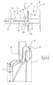
- FIG. 1 shows in the perspective view of a laundry treatment machine 1, such as a washing machine or a tumble dryer, wherein the washing machine or the tumble dryer with a feed opening 2 closable door 3 is equipped. It is located, represented in the dashed situation of FIG. 1 , a closure assembly 4 on the machine housing, wherein this comprises a arranged on the inside of the door 5 locking element 6, which with a housing-side closure element 7 (FIG. Fig. 2 ) cooperates.
- the operation or the embodiment in different positions of the closure assembly 4 is isolated in the illustrations of Figures 2 . 3 and 4 shown in more detail.
- the locking element 6 is brought by hand under a slight closing pressure of the door 3 with the closure element 7 in operative connection, this situation in the FIG. 2 is shown.
- the unlocked or unlatched situation is in the FIG. 4 shown, wherein here the locking element 6 has detached from the closure element 7 by a pulling movement.
- the door 3 according to the situation of the FIG. 2 assumes an adjacent latching position at the feed opening 2, so that the locking element 6 under a gap 8 with respect to the feed opening 2 and here opposite the seal 9, as shown in the perspective view partially occupies.
- the closure element 7 is now able by means of a motor drive 10 to cause a self-locking and sealing engagement of the door 3 to the feed opening 2, when the motor drive element 10 here pulls the locking element 6 to the machine housing.
- the locking element 6 consists of tongues 11 and 12, the free ends of which can be latched under slight closing pressure with a motor-driven closing element 13 of the closure element 7.
- the closing element 13 consists of a linearly movable slide, which is arranged in a housing 14.
- the housing 14 forms a positive guide for the latched on the slide 13 tongues 11 and 12.
- the forced guidance as such in this case comprises a rectilinear channel 15 into which the latched tongues 11 and 12 are retractable.
- the channel 15 is formed widened in the front region to the housing wall 16, wherein the widening here forms a detent chamber 17 and thus a movement space for the free ends of the tongues 11 and 12.
- the tongues 11 and 12 are formed of two parallel spring steel strips, at the ends of which respective opposite hemispheres 18 and 19 are arranged.
- a bore 20 for receiving the adjacent hemisphere regions is arranged at the free end of the slider 13.
- the bore 20 is clearly in the FIG. 4 can be seen, which is dimensioned such that in particular the hemispheres 18 and 19 in the bore 20 when they are engaged come to rest.
- the slider 13 cooperates for linear movement with an electric motor 21, which can also be equipped with a transmission. It is also conceivable, for example, to provide a lifting magnet or a wax motor, which drives the linear movement of the slide 13 accordingly.
- the operation of the slider 13 takes place via the program of the laundry treatment machine 1, wherein after the locking of the locking element 6 on the slide 13 of the motor 21 is actuated, so that the automatic sealing closure of the door 3 is completed. If the washing program is completed, the motor 21 as a result of the displacement of the slider 13 releases the locking element 6 so far again that the hemispheres 18 and 19 are in the widened locking chamber 17, so that the door 3 can be opened with a slight unlatching.
- the door 3 If the door 3 is closed, press the two hemispheres 18 and 19 in front of the slider 13, while the two tongues 11, 12, which preferably each consist of a spring steel strip, as long as pushed aside until the hemispheres 18 and 19 in the bore 20 of the slider 13 are located. In this position, the door 3 is applied to the seal 9 of the door seal. The door 3 is not locked and can be opened again by train.
- the slider 13 moves into the latch bolt and pulls the door 3 with it, with the case narrows towards the interior of the lock, as determined by the situation of FIG. 3 is pictured. After a short distance, the spring steel strips or tongues 11, 12 no longer have sufficient freedom of movement so that the door 3 is thereby locked. At the same time the door is pressed against the seal 9 of the door sealing ring. The tub is thus sealed.
Landscapes
- Engineering & Computer Science (AREA)
- Textile Engineering (AREA)
- Main Body Construction Of Washing Machines And Laundry Dryers (AREA)
- Detail Structures Of Washing Machines And Dryers (AREA)
- Power-Operated Mechanisms For Wings (AREA)
Abstract
Description
- Die Erfindung betrifft eine Verschlussanordnung für eine Wäschebehandlungsmaschine, wie eine Waschmaschine oder einen Wäschetrockner, mit einer eine Beschickungsöffnung verschließbaren Tür, umfassend ein an der Türinnenseite angeordnetes Riegelelement, welches mit einem gehäuseseitigen Verschlusselement zusammenwirkt.
- Aus dem Stand der Technik sind Verschlussanordnungen bei Waschmaschinen oder Wäschetrocknern bekannt, bei denen die Tür an der Beschickungsöffnung mit einem Riegelelement derart verschlossen wird, dass der Nutzer den Widerstand des Tür- bzw. des Dichtringes überwinden muss. Denn bei den bekannten Verschlussanordnungen ist es erforderlich, dass zur dichtenden Schließung die Tür gegen die Faltenbalgdichtung unter einem Druck in die verriegelnde Situation gebracht werden muss. So muss bei den bekannten Serienschlössern die Tür in den Türdichtring gedrückt werden, was insbesondere das Öffnen und das Schließen erschwert.
- So ist beispielsweise aus dem Stand der Technik gemäß der
EP 1 640 495 A1 eine Drücker- bzw. eine Klinkenverschlussanordnung für einen Wäschetrockner bekannt, welche über ein stabförmiges Riegelelement verfügt, das in eine Verschlussanordnung an der Gehäuseseite eingreift, wobei mittels seitlich angeordneter Federn die Schnapp- bzw. die Verriegelungssituation herbeigeführt wird. - Der Erfindung stellt sich somit das Problem, eine Verschlussanordnung für eine Wäschebehandlungsmaschine derart weiterzubilden, bei der der Öffnungs- bzw. Schließvorgang wesentlich erleichtert wird.
- Erfindungsgemäß wird dieses Problem mit den Merkmalen des Patentanspruchs 1 gelöst. Vorteilhafte Ausgestaltungen und Weiterbildungen der Erfindung ergeben sich aus den nachfolgenden Unteransprüchen.
- Die mit der Erfindung erreichbaren Vorteile bestehen darin, dass mittels der erfindungsgemäßen Verschlussanordnung die Tür mit einem leichten Schließdruck mit dem gehäuseseitigen Verschlusselement zunächst verrastet wird, so dass eine Wirkverbindung zwischen der Tür und dem Gehäuse geschaffen wird. Befindet sich die Tür in der verrasteten Situation, so erfolgt die dichtende Schließung mittels eines motorischen Antriebs, der die selbst verriegelnde und dichtende Anlage der Tür an der Beschickungsöffnung bewirkt. Diese Ausbildung gewährleistet neben der leichten Verschließung auch das leichte Öffnen der Tür, weil bei Beendigung des Waschprogramms das motorische Verschlusselement die Tür aus der verriegelnden Situation wieder freigibt, so dass durch eine leichte Zugbewegung mit der Hand die Beschickungstür wieder geöffnet werden kann. Auch bewirkt der motorische Antrieb immer eine exakt bleibende Bewegung dahingehend, dass sich die Tür mit einem entsprechenden Druck auf die Faltenbalgdichtung legt. Letzteres vermindert den Verschleiß und erhöht somit die Standzeiten der Dichtungen.
- Nach einer besonders vorteilhaften Ausgestaltung der Erfindung besteht das Riegelelement aus Zungen, deren freie Enden unter leichtem Schließdruck mit einem motorisch angetriebenen Schließelement des Verschlusselementes verrasten. Die Zungen haben hierbei die hinreichende Federwirkung, so dass ein leichter Verrastvorgang im Türbereich erfolgen kann. Dabei ist das Schließelement ein linear verfahrbarer Schieber. Der Schieber befindet sich in einem Gehäuse, welches eine Zwangsführung für die an dem Schieber verrasteten Zungen bildet. Die Zwangsführung umfasst einen gradlinig ausgebildeten Kanal, in den die verrasteten Zungen einziehbar sind. Somit ergibt sich eine stabile Verschlusswirkung für die Tür, die gegen ein ungewolltes Lösen gesichert ist.
- Nach einer besonders vorteilhaften Ausgestaltung der Erfindung ist der Kanal im vorderen Bereich zur Gehäusewand hin aufgeweitet ausgebildet, um eine Rastkammer für die freien Enden der Zungen zu bilden. Die Zungen bestehen aus zwei parallel angeordneten Federstahlstreifen, an deren Enden jeweils gegenüberliegend Halbkugeln angebracht oder angeformt sind. Zur Verrastung der gegenüberliegenden Halbkugeln ist am freien Ende des Schiebers eine Bohrung zur Aufnahme der aneinander anliegenden Halbkugelbereiche angeordnet. Es versteht sich nun von selbst, dass, wenn sich der Schieber mit seinem freien Ende, also mit seiner Bohrung in dem aufgeweiteten Gehäuse befindet, sich die beiden halbkugelförmigen Enden der Zungen einfach über den Öffnungsrand der Bohrung hinausdrücken können, so dass sie zur Anlage kommen, um auf diese Weise eine verrastende Verbindung mit dem Schieber herzustellen. Wird der Schieber nun motorisch linear zurück verschoben, so zieht er die beiden aufeinander liegenden Halbkugeln in die Zwangsführung, so dass es zu einer festen Verschlussanordnung kommt.
- In zweckmäßiger Weise wirkt der Schieber zur linearen Bewegung mit einem Elektromotor mit Getriebe, einem Hubmagnet oder einem Wachsmotor zusammen. Der Schieber ist dabei derart gesteuert, dass die Betätigung des Schiebers über das Programm der Wäschebehandlungsmaschine steuerbar ist.
- Ein Ausführungsbeispiel der Erfindung ist in den Zeichnungen rein schematisch dargestellt und wird nachfolgend näher beschrieben. Es zeigen:
- Figur 1
- eine perspektivische Darstellung einer Wäschebehandlungsmaschine mit aufgeklappter Tür;
- Figur 2
- eine Detailansicht in Seitenansicht der Verschlussanordnung in einer ersten verrasteten Situation mit einer perspektivischen Darstellung der Dichtsituation im Bereich der Faltenbalgdichtung;
- Figur 3
- eine weitere Detailansicht ebenfalls in Seitenansicht der Verschlussanordnung in einer zweiten verrasteten Situation ebenfalls mit einer perspektivischen Darstel- lung der Dichtsituation im Bereich der Faltenbalgdichtung und
- Figur 4
- eine weitere Ansicht der Verschlussanordnung gemäß der
Figur 2 und3 in der geöffneten, nicht verrasteten Situation. - Die
Figur 1 zeigt in der perspektivischen Darstellung eine Wäschebehandlungsmaschine 1, wie eine Waschmaschine bzw. einen Wäschetrockner, wobei die Waschmaschine oder der Wäschetrockner mit einer eine Beschickungsöffnung 2 verschließbaren Tür 3 ausgestattet ist. Dabei befindet sich, dargestellt in der gestrichelten Situation derFigur 1 , eine Verschlussanordnung 4 am Maschinengehäuse, wobei diese ein an der Türinnenseite 5 angeordnetes Riegelelement 6 umfasst, welches mit einem gehäuseseitigen Verschlusselement 7 (Fig. 2 ) zusammenwirkt. Die Funktionsweise bzw. die Ausgestaltung in unterschiedlichen Stellungen der Verschlussanordnung 4 ist isoliert in den Darstellungen derFiguren 2 ,3 und4 näher dargestellt. Dabei wird das Riegelelement 6 von Hand unter einem leichten Schließdruck der Tür 3 mit dem Verschlusselement 7 in Wirkverbindung gebracht, wobei diese Situation in derFigur 2 dargestellt ist. Die entriegelte bzw. die entrastete Situation ist in derFigur 4 dargestellt, wobei sich hier das Riegelelement 6 von dem Verschlusselement 7 durch eine Zugbewegung gelöst hat. Die Tür 3 gemäß der Situationsdarstellung derFigur 2 nimmt eine anliegende verrastende Position an der Beschickungsöffnung 2 ein, so dass das Riegelelement 6 unter einer Spaltbildung 8 gegenüber der Beschickungsöffnung 2 bzw. hier gegenüber der Dichtung 9, wie sie in der perspektivischen Darstellung teilweise dargestellt ist, einnimmt. Das Verschlusselement 7 ist nun in der Lage mittels eines motorischen Antriebes 10 eine Selbstverriegelung und dichtende Anlage der Tür 3 an die Beschickungsöffnung 2 zu bewirken, wenn das motorische Antriebselement 10 hier das Riegelelement 6 zum Maschinengehäuse zieht. - Das Riegelelement 6 besteht aus Zungen 11 und 12, deren freie Enden unter leichtem Schließdruck mit einem motorisch angetriebenen Schließelement 13 des Verschlusselementes 7 verrastbar sind. Diese Situation ist in der
Figur 2 dargestellt. Dabei besteht das Schließelement 13 aus einem linear verfahrbaren Schieber, der in einem Gehäuse 14 angeordnet ist. Wie aus derFigur 2 deutlich zu erkennen ist, bildet hierbei das Gehäuse 14 eine Zwangsführung für die an dem Schieber 13 verrasteten Zungen 11 und 12. Die Zwangsführung als solches umfasst hierbei einen gradlinig ausgebildeten Kanal 15, in den die verrasteten Zungen 11 und 12 einziehbar sind. Der Kanal 15 ist im vorderen Bereich zur Gehäusewand 16 hin aufgeweitet ausgebildet, wobei die Aufweitung hier eine Rastkammer 17 und damit einen Bewegungsraum für die freien Enden der Zungen 11 und 12 bildet. Wie aus denFiguren 2 ,3 und4 deutlich zu erkennen ist, sind die Zungen 11 und 12 aus zwei parallel angeordneten Federstahlstreifen gebildet, an deren Enden jeweils gegenüberliegende Halbkugeln 18 und 19 angeordnet sind. Zur Verrastung der gegenüberliegenden Halbkugeln 18 und 19 ist am freien Ende des Schiebers 13 eine Bohrung 20 zur Aufnahme der anliegenden Halbkugelbereiche angeordnet. Die Bohrung 20 ist deutlich in derFigur 4 zu erkennen, die derart bemessen ist, dass insbesondere die Halbkugeln 18 und 19 in der Bohrung 20, wenn sie eingerastet sind, zur Anlage kommen. Wie aus den beidenFiguren 2 und3 zu erkennen ist, wirkt der Schieber 13 zur linearen Bewegung mit einem Elektromotor 21 zusammen, der auch mit einem Getriebe ausgestattet werden kann. Denkbar ist auch beispielsweise einen Hubmagneten oder einen Wachsmotor vorzusehen, der entsprechend die lineare Bewegung des Schiebers 13 antreibt. Die Betätigung des Schiebers 13 erfolgt dabei über das Programm der Wäschebehandlungsmaschine 1, wobei nach dem Verrasten des Riegelelementes 6 an dem Schieber 13 der Motor 21 betätigt wird, so dass die selbsttätige dichtende Verschließung der Tür 3 vollzogen wird. Ist das Waschprogramm beendet, so gibt der Motor 21 infolge des Verschiebens des Schiebers 13 das Riegelelement 6 soweit wieder frei, dass die Halbkugeln 18 und 19 sich in der aufgeweiteten Rastkammer 17 befinden, so dass mit einem leichten Entrasten die Tür 3 geöffnet werden kann. - Wird die Tür 3 geschlossen, drücken die beiden Halbkugeln 18 und 19 vor den Schieber 13, dabei werden die beiden Zungen 11, 12, die vorzugsweise jeweils aus einem Federstahlstreifen bestehen, solange zur Seite gedrückt, bis sich die Halbkugeln 18 und 19 in der Bohrung 20 des Schiebers 13 befinden. In dieser Stellung ist die Tür 3 an der Dichtung 9 des Türdichtringes angelegt. Die Tür 3 ist nicht verriegelt und kann wieder durch Zug geöffnet werden. Wird das Programm gestartet, bewegt sich der Schieber 13 in die Schlossfalle und zieht die Tür 3 dabei mit, wobei sich die Falle zum Schlossinneren verengt, wie dies durch die Situation der
Figur 3 dargestellt wird. Nach einer kurzen Strecke haben die Federstahlstreifen bzw. Zungen 11, 12 keine ausreichende Bewegungsfreiheit mehr so dass dadurch die Tür 3 verriegelt ist. Gleichzeitig wird die Tür an die Dichtung 9 des Türdichtringes gedrückt. Der Laugenbehälter ist somit dicht verschlossen.
Claims (10)
- Verschlussanordnung (4) für eine Wäschebehandlungsmaschine (1), wie eine Waschmaschine oder ein Wäschetrockner, mit einer eine Beschickungsöffnung (2) verschließbaren Tür (3), umfassend ein an der Türinnenseite (5) angeordnetes Riegelelement (6), welches mit einem gehäuseseitigen Verschlusselement (7) zusammenwirkt,
dadurch gekennzeichnet,
dass das Riegelelement (6) unter einem Schließdruck der Tür (3) mit dem Verschlusselement (7) in Wirkverbindung bringbar ist, wobei die Tür (3) eine anliegende verrastende Position zur Beschickungsöffnung (2) einnimmt, wobei das Verschlusselement (7) mittels eines motorischen Antriebs (10) eine selbst verriegelnde und dichtende Anlage der Tür (3) an die Beschickungsöffnung (2) bewirkt. - Verschlussanordnung (4) nach Anspruch 1,
dadurch gekennzeichnet,
dass das Riegelelement (6) aus Zungen (11, 12) besteht, deren freie Enden unter einem Schließdruck mit einem motorisch angetriebenen Schließelement (13) des Verschlusselementes (7) verrastbar sind. - Verschlussanordnung (4) nach Anspruch 2,
dadurch gekennzeichnet,
dass das Schließelement (13) ein linear verfahrbarer Schieber ist. - Verschlussanordnung (4) nach Anspruch 3,
dadurch gekennzeichnet,
dass der Schieber (13) in einem Gehäuse (14) angeordnet ist, welches eine Zwangsführung für die an dem Schieber (13) verrasteten Zungen (11, 12) bildet. - Verschlussanordnung (4) nach Anspruch 4,
dadurch gekennzeichnet,
dass die Zwangsführung einen gradlinig ausgebildeten Kanal (15) umfasst, in den die verrasteten Zungen (11, 12) einziehbar sind. - Verschlussanordnung (4) nach Anspruch 5,
dadurch gekennzeichnet,
dass der Kanal (15) im vorderen Bereich zur Gehäusewand (16) hin aufgeweitet ausgebildet ist, zur Bildung einer Rastkammer (17) für die freien Enden der Zungen (11, 12). - Verschlussanordnung (4) nach Anspruch 6,
dadurch gekennzeichnet,
dass die Zungen (11, 12) aus zwei parallel angeordneten Federstahlstreifen gebildet sind an deren Enden jeweils gegenüberliegend Halbkugeln (18, 19) angebracht oder angeformt sind. - Verschlussanordnung (4) nach Anspruch 7,
dadurch gekennzeichnet,
dass zur Verrastung der gegenüberliegenden Halbkugeln (18, 19) am freien Ende des Schiebers (13) eine Bohrung (20) zur Aufnahme der anliegenden Halbkugelbereiche angeordnet ist. - Verschlussanordnung (4) nach Anspruch 8,
dadurch gekennzeichnet,
dass der Schieber (13) zur linearen Bewegung mit einem Elektromotor (21) mit Getriebe, einem Hubmagnet oder einem Wachsmotor zusammenwirkt. - Verschlussanordnung (4) nach Anspruch 9,
dadurch gekennzeichnet,
dass die Betätigung des Schiebers (13) über das Programm der Wäschebehandlungsmaschine (1) steuerbar ist.
Applications Claiming Priority (1)
| Application Number | Priority Date | Filing Date | Title |
|---|---|---|---|
| DE102009024503A DE102009024503B3 (de) | 2009-06-08 | 2009-06-08 | Verschlussanordnung für eine Wäschebehandlungsmaschine |
Publications (3)
| Publication Number | Publication Date |
|---|---|
| EP2261415A2 true EP2261415A2 (de) | 2010-12-15 |
| EP2261415A3 EP2261415A3 (de) | 2012-08-29 |
| EP2261415B1 EP2261415B1 (de) | 2013-04-03 |
Family
ID=42543004
Family Applications (1)
| Application Number | Title | Priority Date | Filing Date |
|---|---|---|---|
| EP10401072A Not-in-force EP2261415B1 (de) | 2009-06-08 | 2010-06-01 | Verschlussanordnung für eine Wäschebehandlungsmaschine |
Country Status (3)
| Country | Link |
|---|---|
| EP (1) | EP2261415B1 (de) |
| DE (1) | DE102009024503B3 (de) |
| ES (1) | ES2403084T3 (de) |
Cited By (3)
| Publication number | Priority date | Publication date | Assignee | Title |
|---|---|---|---|---|
| WO2013054279A1 (en) * | 2011-10-14 | 2013-04-18 | BSH Bosch und Siemens Hausgeräte GmbH | Washing machine and method for controlling the same |
| WO2014017783A1 (en) * | 2012-07-23 | 2014-01-30 | Lg Electronics Inc. | Lid locker of washing machine |
| RU2584110C1 (ru) * | 2012-04-01 | 2016-05-20 | Бсх Хаусгерете Гмбх | Стиральная машина и способ управления стиральной машиной |
Families Citing this family (8)
| Publication number | Priority date | Publication date | Assignee | Title |
|---|---|---|---|---|
| ES2549538T3 (es) * | 2012-09-25 | 2015-10-29 | Miele & Cie. Kg | Máquina lavadora con una cubeta para la colada y con un equipo de circulación |
| EP3137707B1 (de) * | 2014-05-01 | 2018-08-22 | Illinois Tool Works Inc. | Motorisierter riegel mit geringer schliesskraft |
| DE102015224661B3 (de) * | 2015-12-09 | 2017-05-11 | BSH Hausgeräte GmbH | Haushaltsgerät mit einem Rückstellelement |
| DE102017209390B4 (de) * | 2017-06-02 | 2022-08-11 | BSH Hausgeräte GmbH | Wäschepflegegerät mit einer Öffnungsvorrichtung |
| DE102017213673B4 (de) * | 2017-08-07 | 2022-08-04 | BSH Hausgeräte GmbH | Wäschepflegegerät mit einer Türvorrichtung |
| DE102017214091B4 (de) * | 2017-08-11 | 2022-08-04 | BSH Hausgeräte GmbH | Wäschepflegegerät mit einer Türbewegungsvorrichtung |
| CN112096206B (zh) * | 2019-06-18 | 2024-05-31 | 青岛海尔洗涤电器有限公司 | 一种门体弹出组件、安装方法及衣物处理设备 |
| CN112096204B (zh) * | 2019-06-18 | 2025-07-22 | 青岛海尔洗涤电器有限公司 | 门体弹出组件及衣物处理设备 |
Family Cites Families (3)
| Publication number | Priority date | Publication date | Assignee | Title |
|---|---|---|---|---|
| DE4403834C1 (de) * | 1994-02-08 | 1995-05-11 | Ymos Ag Ind Produkte | Schließvorrichtung |
| DE19549197A1 (de) * | 1995-08-04 | 1997-02-06 | Ellenberger & Poensgen | Elektrische Bearbeitungsmaschine, insbesondere Wasch- oder Trockenmaschine |
| KR20060026316A (ko) * | 2004-09-20 | 2006-03-23 | 삼성전자주식회사 | 래치 어셈블리 및 이를 구비한 건조기 |
-
2009
- 2009-06-08 DE DE102009024503A patent/DE102009024503B3/de active Active
-
2010
- 2010-06-01 EP EP10401072A patent/EP2261415B1/de not_active Not-in-force
- 2010-06-01 ES ES10401072T patent/ES2403084T3/es active Active
Cited By (5)
| Publication number | Priority date | Publication date | Assignee | Title |
|---|---|---|---|---|
| WO2013054279A1 (en) * | 2011-10-14 | 2013-04-18 | BSH Bosch und Siemens Hausgeräte GmbH | Washing machine and method for controlling the same |
| RU2566471C1 (ru) * | 2011-10-14 | 2015-10-27 | Бсх Хаусгерете Гмбх | Стиральная машина и способ управления стиральной машиной |
| RU2584110C1 (ru) * | 2012-04-01 | 2016-05-20 | Бсх Хаусгерете Гмбх | Стиральная машина и способ управления стиральной машиной |
| WO2014017783A1 (en) * | 2012-07-23 | 2014-01-30 | Lg Electronics Inc. | Lid locker of washing machine |
| US9869049B2 (en) | 2012-07-23 | 2018-01-16 | Lg Electronics Inc. | Washing machine having lid locker |
Also Published As
| Publication number | Publication date |
|---|---|
| EP2261415B1 (de) | 2013-04-03 |
| ES2403084T3 (es) | 2013-05-14 |
| EP2261415A3 (de) | 2012-08-29 |
| DE102009024503B3 (de) | 2010-09-23 |
Similar Documents
| Publication | Publication Date | Title |
|---|---|---|
| EP2261415B1 (de) | Verschlussanordnung für eine Wäschebehandlungsmaschine | |
| DE102006007418B4 (de) | Geräte-Schnappschloss mit an einem linearen Wagen angebrachten Drehverriegelungshaken | |
| DE102015002538B3 (de) | Türverschluss für ein elektrisches Haushaltsgerät, beispielsweise Waschmaschine | |
| DE102020124399B3 (de) | Elektrisches Haushaltsgerät und Türverschluss hierfür | |
| DE102006017961A1 (de) | Verschluß für ein Hausgerät | |
| DE102007038648A1 (de) | Türschloss | |
| DE102018008895A1 (de) | Haushaltsgerät mit Türöffner | |
| EP3336292A1 (de) | Verfahren zum betätigen eines türschlosses und türschloss | |
| DE102007033451A1 (de) | Überhub-Türschließvorrichtung für ein elektrisches Haushaltsgerät | |
| DE202012002853U1 (de) | Kraftfahrzeugtürverschluss | |
| DE202014002995U1 (de) | Öffnungsantrieb | |
| DE202014102033U1 (de) | Bowdenzuganordnung | |
| EP2682545A1 (de) | Verschlussanordnung, insbesondere für eine Schiebetür oder ein Schiebefenster, und Schiebetür oder Schiebefenster | |
| EP2634330B1 (de) | Automatikschloss | |
| DE102007009539B3 (de) | Türschließvorrichtung für ein elektrisches Haushaltsgerät | |
| DE102013212514A1 (de) | Türanlage | |
| DE202016103884U1 (de) | Gargerät mit Verriegelungsvorrichtung | |
| DE102007029900B4 (de) | Verriegelungsvorrichtung für die Tür eines Haushaltsgeräts, insbesondere einer Haushalt-Geschirrspülmaschine und Geschirrspülmaschine | |
| DE102017009902A1 (de) | Schlossbetätigungsvorrichtung mit Notöffnungsfunktion | |
| DE102005000078A1 (de) | Schloss | |
| DE202014009557U1 (de) | Schloss,insbesondere Glastürschloss | |
| DE102013013547A1 (de) | Schloss mit Riegel mit Entriegelungspin | |
| EP2634331B1 (de) | Automatikschloss | |
| DE102017118829A1 (de) | Kraftfahrzeugschloss | |
| AT413292B (de) | Vorrichtung zum verrasten eines flügels, eines fensters, einer tür oder dgl. |
Legal Events
| Date | Code | Title | Description |
|---|---|---|---|
| PUAI | Public reference made under article 153(3) epc to a published international application that has entered the european phase |
Free format text: ORIGINAL CODE: 0009012 |
|
| AK | Designated contracting states |
Kind code of ref document: A2 Designated state(s): AL AT BE BG CH CY CZ DE DK EE ES FI FR GB GR HR HU IE IS IT LI LT LU LV MC MK MT NL NO PL PT RO SE SI SK SM TR |
|
| AX | Request for extension of the european patent |
Extension state: BA ME RS |
|
| PUAL | Search report despatched |
Free format text: ORIGINAL CODE: 0009013 |
|
| AK | Designated contracting states |
Kind code of ref document: A3 Designated state(s): AL AT BE BG CH CY CZ DE DK EE ES FI FR GB GR HR HU IE IS IT LI LT LU LV MC MK MT NL NO PL PT RO SE SI SK SM TR |
|
| AX | Request for extension of the european patent |
Extension state: BA ME RS |
|
| RIC1 | Information provided on ipc code assigned before grant |
Ipc: D06F 39/14 20060101AFI20120725BHEP Ipc: D06F 58/04 20060101ALI20120725BHEP |
|
| 17P | Request for examination filed |
Effective date: 20120808 |
|
| GRAP | Despatch of communication of intention to grant a patent |
Free format text: ORIGINAL CODE: EPIDOSNIGR1 |
|
| GRAS | Grant fee paid |
Free format text: ORIGINAL CODE: EPIDOSNIGR3 |
|
| GRAA | (expected) grant |
Free format text: ORIGINAL CODE: 0009210 |
|
| AK | Designated contracting states |
Kind code of ref document: B1 Designated state(s): AL AT BE BG CH CY CZ DE DK EE ES FI FR GB GR HR HU IE IS IT LI LT LU LV MC MK MT NL NO PL PT RO SE SI SK SM TR |
|
| REG | Reference to a national code |
Ref country code: GB Ref legal event code: FG4D Free format text: NOT ENGLISH |
|
| REG | Reference to a national code |
Ref country code: CH Ref legal event code: EP Ref country code: AT Ref legal event code: REF Ref document number: 604826 Country of ref document: AT Kind code of ref document: T Effective date: 20130415 |
|
| REG | Reference to a national code |
Ref country code: ES Ref legal event code: GC2A Effective date: 20130417 |
|
| REG | Reference to a national code |
Ref country code: IE Ref legal event code: FG4D Free format text: LANGUAGE OF EP DOCUMENT: GERMAN |
|
| REG | Reference to a national code |
Ref country code: ES Ref legal event code: FG2A Ref document number: 2403084 Country of ref document: ES Kind code of ref document: T3 Effective date: 20130514 |
|
| REG | Reference to a national code |
Ref country code: DE Ref legal event code: R096 Ref document number: 502010002843 Country of ref document: DE Effective date: 20130529 |
|
| REG | Reference to a national code |
Ref country code: GB Ref legal event code: 746 Effective date: 20130510 |
|
| REG | Reference to a national code |
Ref country code: DE Ref legal event code: R084 Ref document number: 502010002843 Country of ref document: DE Effective date: 20130417 |
|
| PG25 | Lapsed in a contracting state [announced via postgrant information from national office to epo] |
Ref country code: SI Free format text: LAPSE BECAUSE OF FAILURE TO SUBMIT A TRANSLATION OF THE DESCRIPTION OR TO PAY THE FEE WITHIN THE PRESCRIBED TIME-LIMIT Effective date: 20130403 |
|
| REG | Reference to a national code |
Ref country code: NL Ref legal event code: VDEP Effective date: 20130403 |
|
| REG | Reference to a national code |
Ref country code: LT Ref legal event code: MG4D |
|
| PG25 | Lapsed in a contracting state [announced via postgrant information from national office to epo] |
Ref country code: LT Free format text: LAPSE BECAUSE OF FAILURE TO SUBMIT A TRANSLATION OF THE DESCRIPTION OR TO PAY THE FEE WITHIN THE PRESCRIBED TIME-LIMIT Effective date: 20130403 Ref country code: SE Free format text: LAPSE BECAUSE OF FAILURE TO SUBMIT A TRANSLATION OF THE DESCRIPTION OR TO PAY THE FEE WITHIN THE PRESCRIBED TIME-LIMIT Effective date: 20130403 Ref country code: NL Free format text: LAPSE BECAUSE OF FAILURE TO SUBMIT A TRANSLATION OF THE DESCRIPTION OR TO PAY THE FEE WITHIN THE PRESCRIBED TIME-LIMIT Effective date: 20130403 Ref country code: GR Free format text: LAPSE BECAUSE OF FAILURE TO SUBMIT A TRANSLATION OF THE DESCRIPTION OR TO PAY THE FEE WITHIN THE PRESCRIBED TIME-LIMIT Effective date: 20130704 Ref country code: FI Free format text: LAPSE BECAUSE OF FAILURE TO SUBMIT A TRANSLATION OF THE DESCRIPTION OR TO PAY THE FEE WITHIN THE PRESCRIBED TIME-LIMIT Effective date: 20130403 Ref country code: NO Free format text: LAPSE BECAUSE OF FAILURE TO SUBMIT A TRANSLATION OF THE DESCRIPTION OR TO PAY THE FEE WITHIN THE PRESCRIBED TIME-LIMIT Effective date: 20130703 Ref country code: PT Free format text: LAPSE BECAUSE OF FAILURE TO SUBMIT A TRANSLATION OF THE DESCRIPTION OR TO PAY THE FEE WITHIN THE PRESCRIBED TIME-LIMIT Effective date: 20130805 Ref country code: IS Free format text: LAPSE BECAUSE OF FAILURE TO SUBMIT A TRANSLATION OF THE DESCRIPTION OR TO PAY THE FEE WITHIN THE PRESCRIBED TIME-LIMIT Effective date: 20130803 |
|
| PG25 | Lapsed in a contracting state [announced via postgrant information from national office to epo] |
Ref country code: PL Free format text: LAPSE BECAUSE OF FAILURE TO SUBMIT A TRANSLATION OF THE DESCRIPTION OR TO PAY THE FEE WITHIN THE PRESCRIBED TIME-LIMIT Effective date: 20130403 Ref country code: HR Free format text: LAPSE BECAUSE OF FAILURE TO SUBMIT A TRANSLATION OF THE DESCRIPTION OR TO PAY THE FEE WITHIN THE PRESCRIBED TIME-LIMIT Effective date: 20130403 Ref country code: CY Free format text: LAPSE BECAUSE OF FAILURE TO SUBMIT A TRANSLATION OF THE DESCRIPTION OR TO PAY THE FEE WITHIN THE PRESCRIBED TIME-LIMIT Effective date: 20130403 Ref country code: LV Free format text: LAPSE BECAUSE OF FAILURE TO SUBMIT A TRANSLATION OF THE DESCRIPTION OR TO PAY THE FEE WITHIN THE PRESCRIBED TIME-LIMIT Effective date: 20130403 Ref country code: BG Free format text: LAPSE BECAUSE OF FAILURE TO SUBMIT A TRANSLATION OF THE DESCRIPTION OR TO PAY THE FEE WITHIN THE PRESCRIBED TIME-LIMIT Effective date: 20130703 |
|
| BERE | Be: lapsed |
Owner name: MIELE & CIE. K.G. Effective date: 20130630 |
|
| PG25 | Lapsed in a contracting state [announced via postgrant information from national office to epo] |
Ref country code: EE Free format text: LAPSE BECAUSE OF FAILURE TO SUBMIT A TRANSLATION OF THE DESCRIPTION OR TO PAY THE FEE WITHIN THE PRESCRIBED TIME-LIMIT Effective date: 20130403 Ref country code: SK Free format text: LAPSE BECAUSE OF FAILURE TO SUBMIT A TRANSLATION OF THE DESCRIPTION OR TO PAY THE FEE WITHIN THE PRESCRIBED TIME-LIMIT Effective date: 20130403 Ref country code: DK Free format text: LAPSE BECAUSE OF FAILURE TO SUBMIT A TRANSLATION OF THE DESCRIPTION OR TO PAY THE FEE WITHIN THE PRESCRIBED TIME-LIMIT Effective date: 20130403 Ref country code: CZ Free format text: LAPSE BECAUSE OF FAILURE TO SUBMIT A TRANSLATION OF THE DESCRIPTION OR TO PAY THE FEE WITHIN THE PRESCRIBED TIME-LIMIT Effective date: 20130403 |
|
| PLBE | No opposition filed within time limit |
Free format text: ORIGINAL CODE: 0009261 |
|
| STAA | Information on the status of an ep patent application or granted ep patent |
Free format text: STATUS: NO OPPOSITION FILED WITHIN TIME LIMIT |
|
| PG25 | Lapsed in a contracting state [announced via postgrant information from national office to epo] |
Ref country code: RO Free format text: LAPSE BECAUSE OF FAILURE TO SUBMIT A TRANSLATION OF THE DESCRIPTION OR TO PAY THE FEE WITHIN THE PRESCRIBED TIME-LIMIT Effective date: 20130403 |
|
| 26N | No opposition filed |
Effective date: 20140106 |
|
| REG | Reference to a national code |
Ref country code: IE Ref legal event code: MM4A |
|
| PG25 | Lapsed in a contracting state [announced via postgrant information from national office to epo] |
Ref country code: BE Free format text: LAPSE BECAUSE OF NON-PAYMENT OF DUE FEES Effective date: 20130630 |
|
| REG | Reference to a national code |
Ref country code: DE Ref legal event code: R097 Ref document number: 502010002843 Country of ref document: DE Effective date: 20140106 |
|
| PG25 | Lapsed in a contracting state [announced via postgrant information from national office to epo] |
Ref country code: IE Free format text: LAPSE BECAUSE OF NON-PAYMENT OF DUE FEES Effective date: 20130601 |
|
| REG | Reference to a national code |
Ref country code: CH Ref legal event code: PL |
|
| PG25 | Lapsed in a contracting state [announced via postgrant information from national office to epo] |
Ref country code: MT Free format text: LAPSE BECAUSE OF FAILURE TO SUBMIT A TRANSLATION OF THE DESCRIPTION OR TO PAY THE FEE WITHIN THE PRESCRIBED TIME-LIMIT Effective date: 20130403 |
|
| PG25 | Lapsed in a contracting state [announced via postgrant information from national office to epo] |
Ref country code: CH Free format text: LAPSE BECAUSE OF NON-PAYMENT OF DUE FEES Effective date: 20140630 Ref country code: LI Free format text: LAPSE BECAUSE OF NON-PAYMENT OF DUE FEES Effective date: 20140630 |
|
| PG25 | Lapsed in a contracting state [announced via postgrant information from national office to epo] |
Ref country code: SM Free format text: LAPSE BECAUSE OF FAILURE TO SUBMIT A TRANSLATION OF THE DESCRIPTION OR TO PAY THE FEE WITHIN THE PRESCRIBED TIME-LIMIT Effective date: 20130403 |
|
| PG25 | Lapsed in a contracting state [announced via postgrant information from national office to epo] |
Ref country code: TR Free format text: LAPSE BECAUSE OF FAILURE TO SUBMIT A TRANSLATION OF THE DESCRIPTION OR TO PAY THE FEE WITHIN THE PRESCRIBED TIME-LIMIT Effective date: 20130403 |
|
| PG25 | Lapsed in a contracting state [announced via postgrant information from national office to epo] |
Ref country code: LU Free format text: LAPSE BECAUSE OF NON-PAYMENT OF DUE FEES Effective date: 20130601 Ref country code: MC Free format text: LAPSE BECAUSE OF FAILURE TO SUBMIT A TRANSLATION OF THE DESCRIPTION OR TO PAY THE FEE WITHIN THE PRESCRIBED TIME-LIMIT Effective date: 20130403 Ref country code: HU Free format text: LAPSE BECAUSE OF FAILURE TO SUBMIT A TRANSLATION OF THE DESCRIPTION OR TO PAY THE FEE WITHIN THE PRESCRIBED TIME-LIMIT; INVALID AB INITIO Effective date: 20100601 Ref country code: MK Free format text: LAPSE BECAUSE OF FAILURE TO SUBMIT A TRANSLATION OF THE DESCRIPTION OR TO PAY THE FEE WITHIN THE PRESCRIBED TIME-LIMIT Effective date: 20130403 |
|
| REG | Reference to a national code |
Ref country code: FR Ref legal event code: PLFP Year of fee payment: 7 |
|
| REG | Reference to a national code |
Ref country code: AT Ref legal event code: MM01 Ref document number: 604826 Country of ref document: AT Kind code of ref document: T Effective date: 20150601 |
|
| PG25 | Lapsed in a contracting state [announced via postgrant information from national office to epo] |
Ref country code: AT Free format text: LAPSE BECAUSE OF NON-PAYMENT OF DUE FEES Effective date: 20150601 |
|
| REG | Reference to a national code |
Ref country code: FR Ref legal event code: PLFP Year of fee payment: 8 |
|
| REG | Reference to a national code |
Ref country code: FR Ref legal event code: PLFP Year of fee payment: 9 |
|
| PG25 | Lapsed in a contracting state [announced via postgrant information from national office to epo] |
Ref country code: AL Free format text: LAPSE BECAUSE OF FAILURE TO SUBMIT A TRANSLATION OF THE DESCRIPTION OR TO PAY THE FEE WITHIN THE PRESCRIBED TIME-LIMIT Effective date: 20130403 |
|
| P01 | Opt-out of the competence of the unified patent court (upc) registered |
Effective date: 20230529 |
|
| PGFP | Annual fee paid to national office [announced via postgrant information from national office to epo] |
Ref country code: FR Payment date: 20230622 Year of fee payment: 14 Ref country code: DE Payment date: 20230630 Year of fee payment: 14 |
|
| PGFP | Annual fee paid to national office [announced via postgrant information from national office to epo] |
Ref country code: IT Payment date: 20230620 Year of fee payment: 14 Ref country code: GB Payment date: 20230620 Year of fee payment: 14 Ref country code: ES Payment date: 20230721 Year of fee payment: 14 |
|
| REG | Reference to a national code |
Ref country code: DE Ref legal event code: R119 Ref document number: 502010002843 Country of ref document: DE |
|
| GBPC | Gb: european patent ceased through non-payment of renewal fee |
Effective date: 20240601 |
|
| PG25 | Lapsed in a contracting state [announced via postgrant information from national office to epo] |
Ref country code: DE Free format text: LAPSE BECAUSE OF NON-PAYMENT OF DUE FEES Effective date: 20250101 |
|
| PG25 | Lapsed in a contracting state [announced via postgrant information from national office to epo] |
Ref country code: FR Free format text: LAPSE BECAUSE OF NON-PAYMENT OF DUE FEES Effective date: 20240630 |
|
| PG25 | Lapsed in a contracting state [announced via postgrant information from national office to epo] |
Ref country code: IT Free format text: LAPSE BECAUSE OF NON-PAYMENT OF DUE FEES Effective date: 20240601 Ref country code: GB Free format text: LAPSE BECAUSE OF NON-PAYMENT OF DUE FEES Effective date: 20240601 |
|
| REG | Reference to a national code |
Ref country code: ES Ref legal event code: FD2A Effective date: 20250728 |
|
| PG25 | Lapsed in a contracting state [announced via postgrant information from national office to epo] |
Ref country code: ES Free format text: LAPSE BECAUSE OF NON-PAYMENT OF DUE FEES Effective date: 20240602 |