EP1640495A1 - Latch assembly and drying machine having the same - Google Patents
Latch assembly and drying machine having the same Download PDFInfo
- Publication number
- EP1640495A1 EP1640495A1 EP05252772A EP05252772A EP1640495A1 EP 1640495 A1 EP1640495 A1 EP 1640495A1 EP 05252772 A EP05252772 A EP 05252772A EP 05252772 A EP05252772 A EP 05252772A EP 1640495 A1 EP1640495 A1 EP 1640495A1
- Authority
- EP
- European Patent Office
- Prior art keywords
- latch
- main body
- protrusion
- space
- protrusions
- Prior art date
- Legal status (The legal status is an assumption and is not a legal conclusion. Google has not performed a legal analysis and makes no representation as to the accuracy of the status listed.)
- Withdrawn
Links
Images


Classifications
-
- D—TEXTILES; PAPER
- D06—TREATMENT OF TEXTILES OR THE LIKE; LAUNDERING; FLEXIBLE MATERIALS NOT OTHERWISE PROVIDED FOR
- D06F—LAUNDERING, DRYING, IRONING, PRESSING OR FOLDING TEXTILE ARTICLES
- D06F39/00—Details of washing machines not specific to a single type of machines covered by groups D06F9/00 - D06F27/00
- D06F39/12—Casings; Tubs
- D06F39/14—Doors or covers; Securing means therefor
-
- D—TEXTILES; PAPER
- D06—TREATMENT OF TEXTILES OR THE LIKE; LAUNDERING; FLEXIBLE MATERIALS NOT OTHERWISE PROVIDED FOR
- D06F—LAUNDERING, DRYING, IRONING, PRESSING OR FOLDING TEXTILE ARTICLES
- D06F37/00—Details specific to washing machines covered by groups D06F21/00 - D06F25/00
- D06F37/42—Safety arrangements, e.g. for stopping rotation of the receptacle upon opening of the casing door
-
- D—TEXTILES; PAPER
- D06—TREATMENT OF TEXTILES OR THE LIKE; LAUNDERING; FLEXIBLE MATERIALS NOT OTHERWISE PROVIDED FOR
- D06F—LAUNDERING, DRYING, IRONING, PRESSING OR FOLDING TEXTILE ARTICLES
- D06F58/00—Domestic laundry dryers
- D06F58/02—Domestic laundry dryers having dryer drums rotating about a horizontal axis
- D06F58/04—Details
-
- E—FIXED CONSTRUCTIONS
- E05—LOCKS; KEYS; WINDOW OR DOOR FITTINGS; SAFES
- E05B—LOCKS; ACCESSORIES THEREFOR; HANDCUFFS
- E05B9/00—Lock casings or latch-mechanism casings ; Fastening locks or fasteners or parts thereof to the wing
- E05B9/08—Fastening locks or fasteners or parts thereof, e.g. the casings of latch-bolt locks or cylinder locks to the wing
-
- E—FIXED CONSTRUCTIONS
- E05—LOCKS; KEYS; WINDOW OR DOOR FITTINGS; SAFES
- E05C—BOLTS OR FASTENING DEVICES FOR WINGS, SPECIALLY FOR DOORS OR WINDOWS
- E05C19/00—Other devices specially designed for securing wings, e.g. with suction cups
- E05C19/02—Automatic catches, i.e. released by pull or pressure on the wing
- E05C19/028—Automatic catches, i.e. released by pull or pressure on the wing with sliding bolt(s)
Definitions
- An apparatus consistent with the present invention relates to a latch assembly, which is simply and rapidly assembled, and a drying machine having the same.
- each of a drying machine and a washing machine comprises a cabinet having an opening formed through the front surface thereof, and a door installed at the front surface of the cabinet for opening and closing the opening, thereby allowing laundry to be put into or taken out of the cabinet through the opening under the condition that the door is opened.
- a dishwasher comprises a cabinet having an opened front surface, and a door installed at the front surface of the cabinet, thereby allowing dishes to be put into or taken out of the cabinet under the condition that the door is opened.
- each of the washing machine, the drying machine, and the dishwasher which has a structure in which a latch assembly is installed on the cabinet and a hook is installed on the door
- the hook is inserted into the latch assembly, thereby causing the door to close the opening of the cabinet.
- the hook is separated from the latch assembly, thereby causing the door to open the opening of the cabinet.
- Korean Patent Laid-open Publication No. 10-2004-0046964 discloses a latch assembly, comprising a latch main body having a pair of holders and springs, and a latch cover installed on the front surface of the latch main body, and a drying machine having the latch assembly.
- the latch assembly disclosed by the above Korean Patent Publication has a structure such that the latch main body and the latch cover are connected by a plurality of screws, thereby being disadvantageous in that it has a complicated assembly process and an increased assembly time.
- Illustrative, non-limiting embodiments of the present invention overcome the above disadvantages and other disadvantages not described above. Also, embodiments of the present invention are not required to overcome the disadvantages described above, and an illustrative, non-limiting embodiment of the present invention may not overcome any of the problems described above.
- an aim of embodiments of the invention is to provide a latch assembly, which is simply and rapidly assembled, and a drying machine having the same.
- the present invention provides a latch assembly comprising: a latch main body for locking or unlocking a hook installed on a door; and a latch cover for covering the latch main body, wherein the latch main body includes at least one protrusion, and the latch cover includes at least one protrusion-receiving hole, by which the protrusion is caught, so that the latch main body and the latch cover are assembled in a one-touch fashion.
- the latch main body may include a base portion, and an operating portion perpendicularly extended from a surface of the base portion, and the latch cover may include a planar portion, and an extended portion perpendicularly extended from an edge of the planar portion, so that the extended portion of the latch cover covers the operating portion of the latch main body.
- a pair of the protrusions may be formed on an outer surface of the operating portion of the latch main body such that the protrusions are opposite to each other, and a pair of the protrusion-receiving holes corresponding to the protrusions may be formed in two sides of the extended portion of the latch cover such that the protrusion-receiving holes are opposite to each other.
- Fixing protrusions may be formed on ends of the opposite sides of the extended portion of the latch cover provided with the protrusion-receiving holes, and fixing holes, into which the fixing protrusions are inserted, may be formed in the base portion of the latch main body, thereby allowing the latch cover to be firmly fixed to the latch main body.
- the inside of the operating portion of the latch main body may be divided into a first space, a second space, and a third space communicating with the first and second spaces; and a first spring and a first holder may be installed in the first space, and a second spring and a second holder are installed in the second space, so that the hook is locked or unlocked by the action of the first and second springs and the first and second holders.
- Each of the first and second holders may include a guide protrusion protruding toward the planar portion of the latch cover, and a pair of guide holes for receiving and guiding the guide protrusions may be formed through the planar portion of the latch cover, thereby allowing the first and second holders to move stably back and forth.
- Each of the first and second holders may include a latch unit protruding toward the third space so that the first and second holders are pushed toward the third space by the first and second springs, thereby causing both side surfaces of the hook to be caught and locked by the latch units.
- the present invention provides a drying machine comprising a front panel having an opening, a door hinged to the front panel to open and close the opening, a hook installed on the door, and a latch assembly installed in the front panel for locking and unlocking the hook, wherein the latch assembly includes a latch main body having at least one protrusion, and a latch cover having at least one protrusion-receiving hole, by which the protrusion is caught, so that the latch main body and the latch cover are assembled in a one-touch fashion.
- a plurality of screw holes may be formed in the base portion of the latch assembly, thereby connecting the latch assembly to the front panel using screws.
- FIG. 1 is a front perspective view of the external appearance of a drying machine having a latch assembly in accordance with an embodiment of the present invention
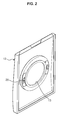
- FIG. 2 is a rear perspective view of a front panel provided with the latch assembly, shown in FIG. 1, connected to the rear surface thereof.
- the drying machine 10 comprises a cabinet 11 having the opened front surface thereof, a front panel 12 installed on the opened front surface of the cabinet 11, and a door 14 for opening and closing a circular-shaped opening 13 formed through the central area of the front panel 12.
- the door 14 is hinged to the front panel 12 by a hinge member 15 formed at one side of the opening 13, thereby being rotatably installed on the front panel 12.
- a hook 16 is protruded from one side of the rear surface of the door 14, opposite to the hinge member 15, toward the front panel 12.
- a hole 17 is formed at the other side of the opening 13 in the front panel 12 opposite to the hinge member 15, and a latch assembly 20 of the present invention is installed in the hole 17. That is, when the latch assembly 20 is inserted into the hole 17 and screwed to the hole 17, as shown in FIG. 2, the latch assembly 20 passes through the hole 17 and protrudes toward the inside of the front panel 12, thereby being capable of locking or unlocking the hook 16 formed on the door 14, thus causing the door 14 to open and close the opening 13 formed through the front panel 12.
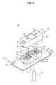
- FIGS. 3 and 4 are respectively exploded and assembled perspective views of the latch assembly 20 consistent with embodiments of the present invention
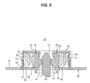
- FIG. 5 is a longitudinal-sectional view taken along the line V-V of FIG. 4.
- the latch assembly 20 includes a latch main body 30 for receiving or releasing the hook 16 installed on the door 14 to perform a locking or unlocking operation, and a latch cover 50 assembled with the latch main body 30.
- the latch main body 30 includes a base portion 31 having a plate shape, and an operating portion 32 perpendicularly extended from the surface of the base portion 31 so as to have an approximately hollow hexahedral structure, thereby forming an external appearance.
- the latch cover 50 includes a planar portion 51 having a size corresponding to the size of the cross-section of the operating portion 32, and an extended portion 52 perpendicularly extended from the edge of the planar portion 51 so as to have a hollow hexahedral structure corresponding to the operating portion 32, thereby forming an external appearance.
- Protrusions 33 are protruded from opposite side surfaces of the operating portion 32 of the latch main body 30, and fixing holes 34, which are positioned just below the protrusions 33 of the operating portion 32, are formed through opposite side surfaces of the base portion 31 of the latch main body 30 (with reference to FIG. 5).
- Protrusion-receiving holes 53 corresponding to the protrusions 33 are formed through opposite side surfaces of the extended portion 52 of the latch cover 50, and fixing protrusions 54 corresponding to the fixing holes 34 of the latch main body 30 are protruded from ends of the opposite side surfaces of the extended portion 52 provided with the protrusion-receiving holes 53.
- the extended portion 52 of the latch cover 50 is placed on the operating portion 32 of the latch main body 30 and then pressed onto the operating portion 32 by a small intensity of force, as shown in FIG. 5, the operating portion 32 is inserted into the extended portion 52.
- the protrusions 33 of the latch main body 30 are caught by the protrusion-receiving holes 53 of the latch cover 50, and simultaneously, the fixing protrusions 54 of the latch cover 50 are inserted into the fixing holes 34 of the latch main body 30, thereby assembling the latch cover 50 with the latch main body 30 in a one-touch fashion.
- the above assembly structure allows the latch cover 50 to maintain its firm fixation to the latch main body 30.
- the inside of the operating portion 32 of the latch main body 30 is divided into a first space 43, a second space 44, and a third space 45 communicating with the first and second spaces 43 and 44 through a pair of partitions 35 disposed in a transverse direction.
- the upper and lower surfaces of the third space 45 are opened so that the hook 16 of the door 14 is inserted into or separated from the operating portion 32 through the third space 45 (with reference to FIG. 5).
- a first spring 36 and a first holder 38 are installed in the first space 43 such that the first spring 36 and the first holder 38 can move back and forth, and a second spring 37 and a second holder 39 are installed in the second space 44 such that the second spring 37 and the second holder 39 can move back and forth.
- each of the first holder 38 and the second holder 39 includes a guide protrusion 40 protruding toward the planar portion 51 of the latch cover 50, and a latch unit 41 protruded from the guide protrusion 40 toward the third space 45.
- the latch cover 50 includes a pair of guide holes 55 formed longitudinally along the first and second spaces 43 and 44.
- the guide protrusions 40 of the first and second holders 38 and 39 pushed toward the third space 45 by the first and second springs 36 and 37 are respectively inserted into the guide holes 55 formed through the planar portion 51 of the latch cover 50, thereby causing the first and second holders 38 and 39 to move stably back and forth in the first and second spaces 43 and 44.
- the latch units 41 of the first and second holders 38 and 39 lock or unlock of the hook 16 by the above back and forth movement of the first and second holders 38 and 39.
- Screw holes 42 are formed in two corners, which face diagonally, of the base portion 31 of the latch main body 30, thereby connecting the latch assembly 20 and the front panel 12 using screws.
- the latch assembly 20 may be applied to other products provided with a door, such as a washing machine and a dishwasher.
- embodiments of the present invention provide a latch assembly, in which a latch main body and a latch cover are firmly assembled in a one-touch fashion, and a drying machine having the latch assembly.
- a latch assembly in which a latch main body and a latch cover are firmly assembled in a one-touch fashion, and a drying machine having the latch assembly.
Landscapes
- Engineering & Computer Science (AREA)
- Mechanical Engineering (AREA)
- Textile Engineering (AREA)
- Main Body Construction Of Washing Machines And Laundry Dryers (AREA)
- Connection Of Plates (AREA)
- Drying Of Solid Materials (AREA)
Abstract
Description
- An apparatus consistent with the present invention relates to a latch assembly, which is simply and rapidly assembled, and a drying machine having the same.
- Generally, each of a drying machine and a washing machine comprises a cabinet having an opening formed through the front surface thereof, and a door installed at the front surface of the cabinet for opening and closing the opening, thereby allowing laundry to be put into or taken out of the cabinet through the opening under the condition that the door is opened. Further, in the same manner as the drying or washing machine, a dishwasher comprises a cabinet having an opened front surface, and a door installed at the front surface of the cabinet, thereby allowing dishes to be put into or taken out of the cabinet under the condition that the door is opened.
- In each of the washing machine, the drying machine, and the dishwasher, which has a structure in which a latch assembly is installed on the cabinet and a hook is installed on the door, when the door is pushed toward the front surface of the cabinet, the hook is inserted into the latch assembly, thereby causing the door to close the opening of the cabinet. Further, when the door is drawn by force having a designated intensity, the hook is separated from the latch assembly, thereby causing the door to open the opening of the cabinet.
- For example, Korean Patent Laid-open Publication No. 10-2004-0046964 discloses a latch assembly, comprising a latch main body having a pair of holders and springs, and a latch cover installed on the front surface of the latch main body, and a drying machine having the latch assembly.
- The latch assembly disclosed by the above Korean Patent Publication has a structure such that the latch main body and the latch cover are connected by a plurality of screws, thereby being disadvantageous in that it has a complicated assembly process and an increased assembly time.
- Illustrative, non-limiting embodiments of the present invention overcome the above disadvantages and other disadvantages not described above. Also, embodiments of the present invention are not required to overcome the disadvantages described above, and an illustrative, non-limiting embodiment of the present invention may not overcome any of the problems described above.
- Therefore, an aim of embodiments of the invention is to provide a latch assembly, which is simply and rapidly assembled, and a drying machine having the same.
- In accordance with one aspect, the present invention provides a latch assembly comprising: a latch main body for locking or unlocking a hook installed on a door; and a latch cover for covering the latch main body, wherein the latch main body includes at least one protrusion, and the latch cover includes at least one protrusion-receiving hole, by which the protrusion is caught, so that the latch main body and the latch cover are assembled in a one-touch fashion.
- The latch main body may include a base portion, and an operating portion perpendicularly extended from a surface of the base portion, and the latch cover may include a planar portion, and an extended portion perpendicularly extended from an edge of the planar portion, so that the extended portion of the latch cover covers the operating portion of the latch main body.
- A pair of the protrusions may be formed on an outer surface of the operating portion of the latch main body such that the protrusions are opposite to each other, and a pair of the protrusion-receiving holes corresponding to the protrusions may be formed in two sides of the extended portion of the latch cover such that the protrusion-receiving holes are opposite to each other.
- Fixing protrusions may be formed on ends of the opposite sides of the extended portion of the latch cover provided with the protrusion-receiving holes, and fixing holes, into which the fixing protrusions are inserted, may be formed in the base portion of the latch main body, thereby allowing the latch cover to be firmly fixed to the latch main body.
- The inside of the operating portion of the latch main body may be divided into a first space, a second space, and a third space communicating with the first and second spaces; and a first spring and a first holder may be installed in the first space, and a second spring and a second holder are installed in the second space, so that the hook is locked or unlocked by the action of the first and second springs and the first and second holders.
- Each of the first and second holders may include a guide protrusion protruding toward the planar portion of the latch cover, and a pair of guide holes for receiving and guiding the guide protrusions may be formed through the planar portion of the latch cover, thereby allowing the first and second holders to move stably back and forth.
- Each of the first and second holders may include a latch unit protruding toward the third space so that the first and second holders are pushed toward the third space by the first and second springs, thereby causing both side surfaces of the hook to be caught and locked by the latch units.
- In accordance with another aspect, the present invention provides a drying machine comprising a front panel having an opening, a door hinged to the front panel to open and close the opening, a hook installed on the door, and a latch assembly installed in the front panel for locking and unlocking the hook, wherein the latch assembly includes a latch main body having at least one protrusion, and a latch cover having at least one protrusion-receiving hole, by which the protrusion is caught, so that the latch main body and the latch cover are assembled in a one-touch fashion.
- A plurality of screw holes may be formed in the base portion of the latch assembly, thereby connecting the latch assembly to the front panel using screws.
- For a better understanding of the invention, and to show how embodiments of the same may be carried into effect, reference will now be made, by way of example, to the accompanying diagrammatic drawings in which:
- FIG. 1 is a front perspective view of the external appearance of a drying machine having a latch assembly consistent with an embodiment of the present invention;
- FIG. 2 is a rear perspective view of a front panel provided with the latch assembly, shown in FIG. 1, connected to the rear surface thereof;
- FIG. 3 is an exploded perspective view of the latch assembly consistent with an embodiment of the present invention;
- FIG. 4 is an assembled perspective view of the latch assembly consistent with an embodiment of the present invention; and
- FIG. 5 is a longitudinal-sectional view taken along the line V-V of FIG. 4.
- Reference will now be made in detail to an exemplary embodiment of the present invention, an example of which is illustrated in the accompanying drawings, wherein like reference numerals refer to like elements throughout. The embodiment is described below to explain the present invention by referring to the annexed drawings.
- FIG. 1 is a front perspective view of the external appearance of a drying machine having a latch assembly in accordance with an embodiment of the present invention, and FIG. 2 is a rear perspective view of a front panel provided with the latch assembly, shown in FIG. 1, connected to the rear surface thereof.
- As shown in FIG. 1, the
drying machine 10 comprises acabinet 11 having the opened front surface thereof, afront panel 12 installed on the opened front surface of thecabinet 11, and adoor 14 for opening and closing a circular-shaped opening 13 formed through the central area of thefront panel 12. - The
door 14 is hinged to thefront panel 12 by ahinge member 15 formed at one side of theopening 13, thereby being rotatably installed on thefront panel 12. Ahook 16 is protruded from one side of the rear surface of thedoor 14, opposite to thehinge member 15, toward thefront panel 12. - A
hole 17 is formed at the other side of the opening 13 in thefront panel 12 opposite to thehinge member 15, and alatch assembly 20 of the present invention is installed in thehole 17. That is, when thelatch assembly 20 is inserted into thehole 17 and screwed to thehole 17, as shown in FIG. 2, thelatch assembly 20 passes through thehole 17 and protrudes toward the inside of thefront panel 12, thereby being capable of locking or unlocking thehook 16 formed on thedoor 14, thus causing thedoor 14 to open and close theopening 13 formed through thefront panel 12. - Hereinafter, with reference to FIGS. 3 to 5, the structure and function of the
latch assembly 20 according to embodiments of the present invention will be described in detail. - FIGS. 3 and 4 are respectively exploded and assembled perspective views of the
latch assembly 20 consistent with embodiments of the present invention, and FIG. 5 is a longitudinal-sectional view taken along the line V-V of FIG. 4. - As shown in FIG. 3, the
latch assembly 20 includes a latchmain body 30 for receiving or releasing thehook 16 installed on thedoor 14 to perform a locking or unlocking operation, and alatch cover 50 assembled with the latchmain body 30. - The latch
main body 30 includes abase portion 31 having a plate shape, and anoperating portion 32 perpendicularly extended from the surface of thebase portion 31 so as to have an approximately hollow hexahedral structure, thereby forming an external appearance. Thelatch cover 50 includes aplanar portion 51 having a size corresponding to the size of the cross-section of theoperating portion 32, and an extendedportion 52 perpendicularly extended from the edge of theplanar portion 51 so as to have a hollow hexahedral structure corresponding to theoperating portion 32, thereby forming an external appearance. -
Protrusions 33 are protruded from opposite side surfaces of theoperating portion 32 of the latchmain body 30, and fixingholes 34, which are positioned just below theprotrusions 33 of theoperating portion 32, are formed through opposite side surfaces of thebase portion 31 of the latch main body 30 (with reference to FIG. 5). - Protrusion-receiving
holes 53 corresponding to theprotrusions 33 are formed through opposite side surfaces of the extendedportion 52 of thelatch cover 50, andfixing protrusions 54 corresponding to thefixing holes 34 of the latchmain body 30 are protruded from ends of the opposite side surfaces of the extendedportion 52 provided with the protrusion-receivingholes 53. - Accordingly, when the extended
portion 52 of thelatch cover 50 is placed on theoperating portion 32 of the latchmain body 30 and then pressed onto theoperating portion 32 by a small intensity of force, as shown in FIG. 5, theoperating portion 32 is inserted into the extendedportion 52. Here, theprotrusions 33 of the latchmain body 30 are caught by the protrusion-receivingholes 53 of thelatch cover 50, and simultaneously, thefixing protrusions 54 of thelatch cover 50 are inserted into thefixing holes 34 of the latchmain body 30, thereby assembling thelatch cover 50 with the latchmain body 30 in a one-touch fashion. Even when impact or vibration is applied to the latchmain body 30 and thelatch cover 50 or the latchmain body 30 and thelatch cover 50 are thermally deformed, the above assembly structure allows thelatch cover 50 to maintain its firm fixation to the latchmain body 30. - As shown in FIG. 3, the inside of the
operating portion 32 of the latchmain body 30 is divided into afirst space 43, asecond space 44, and athird space 45 communicating with the first andsecond spaces partitions 35 disposed in a transverse direction. The upper and lower surfaces of thethird space 45 are opened so that thehook 16 of thedoor 14 is inserted into or separated from theoperating portion 32 through the third space 45 (with reference to FIG. 5). - A
first spring 36 and afirst holder 38 are installed in thefirst space 43 such that thefirst spring 36 and thefirst holder 38 can move back and forth, and asecond spring 37 and asecond holder 39 are installed in thesecond space 44 such that thesecond spring 37 and thesecond holder 39 can move back and forth. - As shown in FIG. 5, each of the
first holder 38 and thesecond holder 39 includes aguide protrusion 40 protruding toward theplanar portion 51 of thelatch cover 50, and alatch unit 41 protruded from theguide protrusion 40 toward thethird space 45. Thelatch cover 50 includes a pair ofguide holes 55 formed longitudinally along the first andsecond spaces - Accordingly, when the
latch cover 50 is inserted into the latchmain body 30, as shown in FIGS. 4 and 5, theguide protrusions 40 of the first andsecond holders third space 45 by the first andsecond springs guide holes 55 formed through theplanar portion 51 of thelatch cover 50, thereby causing the first andsecond holders second spaces latch units 41 of the first andsecond holders hook 16 by the above back and forth movement of the first andsecond holders - Screw
holes 42 are formed in two corners, which face diagonally, of thebase portion 31 of the latchmain body 30, thereby connecting thelatch assembly 20 and thefront panel 12 using screws. - Although the exemplary embodiment of the present invention describes the
latch assembly 20 applied to thedrying machine 10, thelatch assembly 20 may be applied to other products provided with a door, such as a washing machine and a dishwasher. - As apparent from the above description, embodiments of the present invention provide a latch assembly, in which a latch main body and a latch cover are firmly assembled in a one-touch fashion, and a drying machine having the latch assembly. Thereby, it is possible to assemble simply and rapidly the latch assembly and to maintain the firm fixation between the latch cover and the latch assembly even when impact or vibration is applied to the latch assembly or the latch assembly is thermally deformed.
- Although an exemplary embodiment of the invention has been shown and described, it would be appreciated by those skilled in the art that changes may be made in this embodiment without departing from the principles and spirit of the invention, the scope of which is defined in the claims and their equivalents.
- Attention is directed to all papers and documents which are filed concurrently with or previous to this specification in connection with this application and which are open to public inspection with this specification, and the contents of all such papers and documents are incorporated herein by reference.
- All of the features disclosed in this specification (including any accompanying claims, abstract and drawings), and/or all of the steps of any method or process so disclosed, may be combined in any combination, except combinations where at least some of such features and/or steps are mutually exclusive.
- Each feature disclosed in this specification (including any accompanying claims, abstract and drawings) may be replaced by alternative features serving the same, equivalent or similar purpose, unless expressly stated otherwise. Thus, unless expressly stated otherwise, each feature disclosed is one example only of a generic series of equivalent or similar features.
- The invention is not restricted to the details of the foregoing embodiment(s). The invention extends to any novel one, or any novel combination, of the features disclosed in this specification (including any accompanying claims, abstract and drawings), or to any novel one, or any novel combination, of the steps of any method or process so disclosed.
Claims (15)
- A latch assembly (20) comprising:a latch main body (30) for locking or unlocking a hook (16) installed on a door (14); anda latch cover (50) for covering the latch main body,wherein the latch main body includes at least one protrusion (33), and the latch cover includes at least one protrusion-receiving hole (53), by which the protrusion is caught, so that the latch main body and the latch cover are assembled in a one-touch fashion.
- The latch assembly according to claim 1,
wherein the latch main body includes a base portion (31), and an operating portion (32) perpendicularly extended from a surface of the base portion, and the latch cover includes a planar portion (51), and an extended portion (52) perpendicularly extended from an edge of the planar portion, so that the extended portion of the latch cover covers the operating portion of the latch main body. - The latch assembly according to claim 2,
wherein a pair of the protrusions (33) are formed on an outer surface of the operating portion (32) of the latch main body such that the protrusions are opposite to each other, and a pair of the protrusion-receiving holes (53) corresponding to the protrusions are formed in two sides of the extended portion (52) of the latch cover such that the protrusion-receiving holes are opposite to each other. - The latch assembly according to claim 3,
wherein fixing protrusions (54) are formed on ends of the opposite sides of the extended portion (52) of the latch cover provided with the protrusion-receiving holes, and fixing holes (34), into which the fixing protrusions are inserted, are formed in the base portion of the latch main body, thereby allowing the latch cover to be firmly fixed to the latch main body. - The latch assembly according to any of claims 2-4, wherein:an inside of the operating portion of the latch main body is divided into a first space (43), a second space (44), and a third space (45) communicating with the first and second spaces; anda first spring (36) and a first holder (38) are installed in the first space, and a second spring (37) and a second holder (39) are installed in the second space, so that the hook (16) moving toward the third space (45) is locked or unlocked by the action of the first and second springs and the first and second holders.
- The latch assembly according to claim 5,
wherein each of the first and second holders (38, 39) includes a guide protrusion (40) protruding toward the planar portion of the latch cover, and a pair of guide holes (55) for receiving and guiding the guide protrusions are formed through the planar portion (51) of the latch cover, thereby allowing the first and second holders to stably move back and forth. - The latch assembly according to claim 5 or 6,
wherein each of the first and second holders (38, 39) includes a latch unit (41) protruding toward the third space (45) so that the first and second holders are pushed toward the third space by the first and second springs, thereby causing both side surfaces of the hook to be caught and locked by the latch units. - A drying machine (10) comprising a front panel (12) having an opening (13), a door (14) hinged to the front panel to open and close the opening, a hook installed on the door, and a latch assembly (20) installed in the front panel for locking and unlocking the hook,
wherein the latch assembly includes a latch main body (30) having at least one protrusion (33), and a latch cover (50) having at least one protrusion-receiving hole (53), by which the protrusion is caught, so that the latch main body and the latch cover are assembled in a one-touch fashion. - The drying machine according to claim 8,
wherein the latch main body (30) includes a base portion (31), and an operating portion (32) perpendicularly extended from a surface of the base portion, and the latch cover (50) includes a planar portion (51), and an extended portion (52) perpendicularly extended from an edge of the planar portion, so that the extended portion of the latch cover covers the operating portion of the latch main body. - The drying machine according to claim 9,
wherein a pair of the protrusions (33) are formed on an outer surface of the operating portion of the latch main body such that the protrusions are opposite to each other, and a pair of the protrusion-receiving holes (53) corresponding to the protrusions are formed in two sides of the extended portion of the latch cover such that the protrusion-receiving holes are opposite to each other. - The drying machine according to claim 10,
wherein fixing protrusions (54) are formed on ends of the opposite sides of the extended portion of the latch cover provided with the protrusion-receiving holes, and fixing holes (34), into which the fixing protrusions are inserted, are formed in the base portion of the latch main body, thereby allowing the latch cover to be firmly fixed to the latch main body. - The drying machine according to any of claims 9-11, wherein:an inside of the operating portion of the latch main body is divided into a first space (43), a second space (44), and a third space (45) communicating with the first and second spaces; anda first spring (36) and a first holder (38) are installed in the first space, and a second spring (37) and a second holder (39) are installed in the second space, so that the hook (16) is locked or unlocked by the action of the first and second springs and the first and second holders.
- The drying machine according to claim 12,
wherein each of the first and second holders includes a guide protrusion (40) protruding toward the planar portion of the latch cover, and a pair of guide holes (55) for receiving and guiding the guide protrusions are formed through the planar portion of the latch cover, thereby allowing the first and second holders to stably move back and forth. - The drying machine according to claim 12 or 13,
wherein each of the first and second holders (38, 39) includes a latch unit (41) protruding toward the third space so that the first and second holders are pushed toward the third space by the first and second springs, thereby causing both side surfaces of the hook to be caught and locked by the latch units. - The drying machine according to any of claims 9-14,
wherein a plurality of screw holes (42) are formed in the base portion of the latch assembly, thereby connecting the latch assembly to the front panel using screws.
Applications Claiming Priority (1)
| Application Number | Priority Date | Filing Date | Title |
|---|---|---|---|
| KR1020040075193A KR20060026316A (en) | 2004-09-20 | 2004-09-20 | Latch assembly and dryer with same |
Publications (1)
| Publication Number | Publication Date |
|---|---|
| EP1640495A1 true EP1640495A1 (en) | 2006-03-29 |
Family
ID=36072322
Family Applications (1)
| Application Number | Title | Priority Date | Filing Date |
|---|---|---|---|
| EP05252772A Withdrawn EP1640495A1 (en) | 2004-09-20 | 2005-05-05 | Latch assembly and drying machine having the same |
Country Status (5)
| Country | Link |
|---|---|
| US (1) | US20060059711A1 (en) |
| EP (1) | EP1640495A1 (en) |
| KR (1) | KR20060026316A (en) |
| CN (1) | CN1752330A (en) |
| RU (1) | RU2294995C2 (en) |
Cited By (4)
| Publication number | Priority date | Publication date | Assignee | Title |
|---|---|---|---|---|
| ITTO20090098A1 (en) * | 2009-02-11 | 2010-08-12 | Bitron Spa | DOOR-LOCKING DEVICE, PARTICULARLY FOR APPLIANCES |
| DE102009024503B3 (en) * | 2009-06-08 | 2010-09-23 | Miele & Cie. Kg | Closure arrangement for a laundry treatment machine |
| WO2019223973A1 (en) | 2018-05-21 | 2019-11-28 | Arcelik Anonim Sirketi | Lock body with elastic pusher |
| WO2020015912A1 (en) | 2018-07-19 | 2020-01-23 | Arcelik Anonim Sirketi | Door fastened by micro switch pin |
Families Citing this family (10)
| Publication number | Priority date | Publication date | Assignee | Title |
|---|---|---|---|---|
| KR101186597B1 (en) * | 2005-05-23 | 2012-09-27 | 엘지전자 주식회사 | Exausting Type of Dryer |
| US20080235935A1 (en) * | 2007-03-06 | 2008-10-02 | Dong Woo Kang | Laundry treating apparatus |
| KR101306041B1 (en) * | 2007-06-25 | 2013-09-09 | 동부대우전자 주식회사 | Dryer having door opening and closing apparatus |
| JP4475317B2 (en) * | 2007-10-18 | 2010-06-09 | パナソニック株式会社 | Drum washing machine |
| KR101360907B1 (en) * | 2007-12-27 | 2014-02-21 | 동부대우전자 주식회사 | Dryer having door opening and closing apparatus |
| MX2010005581A (en) | 2010-05-19 | 2011-11-18 | Mabe Sa De Cv | Door with single glass pane for dryer. |
| WO2012084483A1 (en) * | 2010-12-24 | 2012-06-28 | Arcelik Anonim Sirketi | A washer/dryer comprising a lock |
| KR102360050B1 (en) * | 2015-02-10 | 2022-02-09 | 삼성전자주식회사 | Clothing dryer |
| CN107227586B (en) * | 2016-03-25 | 2023-11-24 | 伊利诺斯工具制品有限公司 | Electric appliance door lock, electromagnetic door lock assembly and electric appliance |
| CN112373955B (en) * | 2020-11-10 | 2022-12-02 | 苏州贝康智能制造有限公司 | Heat preservation cabin convenient to manual intervention and heat preservation cabin system |
Citations (7)
| Publication number | Priority date | Publication date | Assignee | Title |
|---|---|---|---|---|
| DE1821751U (en) * | 1960-08-27 | 1960-11-17 | Telefonbau & Normalzeit Gmbh | HOUSING FOR DISTRIBUTION BOXES OR CONNECTION BOXES |
| DE9010642U1 (en) * | 1990-06-27 | 1990-10-25 | Balogh S.A., Paris | Housings, especially for electronic identification systems |
| EP0610824A1 (en) * | 1993-02-11 | 1994-08-17 | Bauknecht Hausgeräte GmbH | Security door locking for household apparatus, in particular for drier |
| DE19915669A1 (en) * | 1999-04-07 | 2000-10-12 | Ltd Locking Technologies And D | Door locking mechanism for washing machine has jump disc acting on tiltable rocking arm |
| DE10131636A1 (en) * | 2000-06-30 | 2002-01-10 | Bitron Spa | Door locking device, in particular for an electrical household appliance |
| EP1211140A2 (en) * | 2000-12-01 | 2002-06-05 | TRW Automotive Electronics & Components GmbH & Co. KG | Housing for an electronic monitoring device on vehicle parts |
| US20040111916A1 (en) * | 2002-11-28 | 2004-06-17 | Lg Electronics Inc. | Dryer |
Family Cites Families (7)
| Publication number | Priority date | Publication date | Assignee | Title |
|---|---|---|---|---|
| US3394838A (en) * | 1966-11-18 | 1968-07-30 | Phillips Petroleum Co | Closure latch and container |
| US3520568A (en) * | 1969-04-02 | 1970-07-14 | Gen Electric | Door latch for appliance cabinets and the like |
| US4022504A (en) * | 1976-01-12 | 1977-05-10 | Illinois Tool Works Inc. | Latch receptacle |
| DE3021250A1 (en) * | 1980-06-04 | 1981-12-10 | Apparatebau Wilhelm Heibl Gmbh, 8671 Selbitz | Container lid with snap-in closure - has upward projecting spring lip on rim with outward projection engaging small opening in side wall of lid |
| RU3136U1 (en) * | 1995-05-10 | 1996-11-16 | Завод "Сельмаш" | DOOR LOCK |
| IT1296669B1 (en) * | 1997-12-22 | 1999-07-14 | Bitron Spa | DEVICE FOR LOCKING AND UNLOCKING A DOOR OF A HOUSEHOLD APPLIANCE. |
| KR100479102B1 (en) * | 2002-11-29 | 2005-03-28 | 엘지전자 주식회사 | opening-closing structure of door |
-
2004
- 2004-09-20 KR KR1020040075193A patent/KR20060026316A/en not_active Withdrawn
-
2005
- 2005-05-05 EP EP05252772A patent/EP1640495A1/en not_active Withdrawn
- 2005-05-08 CN CNA2005100696911A patent/CN1752330A/en active Pending
- 2005-05-11 RU RU2005114228/12A patent/RU2294995C2/en active
- 2005-05-12 US US11/127,094 patent/US20060059711A1/en not_active Abandoned
Patent Citations (7)
| Publication number | Priority date | Publication date | Assignee | Title |
|---|---|---|---|---|
| DE1821751U (en) * | 1960-08-27 | 1960-11-17 | Telefonbau & Normalzeit Gmbh | HOUSING FOR DISTRIBUTION BOXES OR CONNECTION BOXES |
| DE9010642U1 (en) * | 1990-06-27 | 1990-10-25 | Balogh S.A., Paris | Housings, especially for electronic identification systems |
| EP0610824A1 (en) * | 1993-02-11 | 1994-08-17 | Bauknecht Hausgeräte GmbH | Security door locking for household apparatus, in particular for drier |
| DE19915669A1 (en) * | 1999-04-07 | 2000-10-12 | Ltd Locking Technologies And D | Door locking mechanism for washing machine has jump disc acting on tiltable rocking arm |
| DE10131636A1 (en) * | 2000-06-30 | 2002-01-10 | Bitron Spa | Door locking device, in particular for an electrical household appliance |
| EP1211140A2 (en) * | 2000-12-01 | 2002-06-05 | TRW Automotive Electronics & Components GmbH & Co. KG | Housing for an electronic monitoring device on vehicle parts |
| US20040111916A1 (en) * | 2002-11-28 | 2004-06-17 | Lg Electronics Inc. | Dryer |
Cited By (5)
| Publication number | Priority date | Publication date | Assignee | Title |
|---|---|---|---|---|
| ITTO20090098A1 (en) * | 2009-02-11 | 2010-08-12 | Bitron Spa | DOOR-LOCKING DEVICE, PARTICULARLY FOR APPLIANCES |
| WO2010092528A1 (en) * | 2009-02-11 | 2010-08-19 | Bitron S.P.A. | A door-locking device particularly for a household appliance |
| DE102009024503B3 (en) * | 2009-06-08 | 2010-09-23 | Miele & Cie. Kg | Closure arrangement for a laundry treatment machine |
| WO2019223973A1 (en) | 2018-05-21 | 2019-11-28 | Arcelik Anonim Sirketi | Lock body with elastic pusher |
| WO2020015912A1 (en) | 2018-07-19 | 2020-01-23 | Arcelik Anonim Sirketi | Door fastened by micro switch pin |
Also Published As
| Publication number | Publication date |
|---|---|
| RU2294995C2 (en) | 2007-03-10 |
| KR20060026316A (en) | 2006-03-23 |
| RU2005114228A (en) | 2006-11-20 |
| CN1752330A (en) | 2006-03-29 |
| US20060059711A1 (en) | 2006-03-23 |
Similar Documents
| Publication | Publication Date | Title |
|---|---|---|
| EP1640495A1 (en) | Latch assembly and drying machine having the same | |
| US9145636B2 (en) | Laundry handling apparatus | |
| US6089627A (en) | Striker and base and insert therefor | |
| US8322171B2 (en) | Drum washing machine with supporting hinges | |
| US10815602B2 (en) | Laundry treating apparatus | |
| US20040244435A1 (en) | Washing machine | |
| EP3165667A1 (en) | Laundry treating apparatus | |
| US20040107598A1 (en) | Dryer | |
| KR20110042260A (en) | a drawer | |
| US7178716B2 (en) | Concealed latch handle multi-point locking mailbox | |
| EP1637642A2 (en) | Drying machine | |
| US9771744B2 (en) | Glove box for vehicle | |
| KR101208499B1 (en) | Drum type-laundry device | |
| JP6938522B2 (en) | Clothes processing equipment | |
| KR100309121B1 (en) | Door handle structure in refrigerators | |
| JP2020165197A (en) | Cabinet with electronic lock | |
| KR101295957B1 (en) | Push type locking apparatus for glove box | |
| KR102593128B1 (en) | Bidirectional switchgear of furniture door | |
| KR102933801B1 (en) | Warehouse type cabinet | |
| JP4879422B2 (en) | Storage rack | |
| JP2929375B2 (en) | Enclosure structure of storage body | |
| CN111691774B (en) | Buried hinge system in double-wall furniture | |
| KR102145725B1 (en) | The locking structure of sliding type | |
| JP3428340B2 (en) | Latch shaft mounting structure for cabinet with door | |
| KR102016984B1 (en) | Grip handle for direct locking system |
Legal Events
| Date | Code | Title | Description |
|---|---|---|---|
| PUAI | Public reference made under article 153(3) epc to a published international application that has entered the european phase |
Free format text: ORIGINAL CODE: 0009012 |
|
| AK | Designated contracting states |
Kind code of ref document: A1 Designated state(s): AT BE BG CH CY CZ DE DK EE ES FI FR GB GR HU IE IS IT LI LT LU MC NL PL PT RO SE SI SK TR |
|
| AX | Request for extension of the european patent |
Extension state: AL BA HR LV MK YU |
|
| 17P | Request for examination filed |
Effective date: 20060729 |
|
| AKX | Designation fees paid |
Designated state(s): DE FR GB IT |
|
| 17Q | First examination report despatched |
Effective date: 20070605 |
|
| STAA | Information on the status of an ep patent application or granted ep patent |
Free format text: STATUS: THE APPLICATION IS DEEMED TO BE WITHDRAWN |
|
| 18D | Application deemed to be withdrawn |
Effective date: 20091201 |