EP2249138B1 - Tire testing machine and method for testing tire - Google Patents
Tire testing machine and method for testing tire Download PDFInfo
- Publication number
- EP2249138B1 EP2249138B1 EP09715420A EP09715420A EP2249138B1 EP 2249138 B1 EP2249138 B1 EP 2249138B1 EP 09715420 A EP09715420 A EP 09715420A EP 09715420 A EP09715420 A EP 09715420A EP 2249138 B1 EP2249138 B1 EP 2249138B1
- Authority
- EP
- European Patent Office
- Prior art keywords
- torque
- spindle shaft
- tire
- rotational friction
- rotational
- Prior art date
- Legal status (The legal status is an assumption and is not a legal conclusion. Google has not performed a legal analysis and makes no representation as to the accuracy of the status listed.)
- Active
Links
Images


Classifications
-
- G—PHYSICS
- G01—MEASURING; TESTING
- G01M—TESTING STATIC OR DYNAMIC BALANCE OF MACHINES OR STRUCTURES; TESTING OF STRUCTURES OR APPARATUS, NOT OTHERWISE PROVIDED FOR
- G01M17/00—Testing of vehicles
- G01M17/007—Wheeled or endless-tracked vehicles
- G01M17/02—Tyres
-
- G—PHYSICS
- G01—MEASURING; TESTING
- G01M—TESTING STATIC OR DYNAMIC BALANCE OF MACHINES OR STRUCTURES; TESTING OF STRUCTURES OR APPARATUS, NOT OTHERWISE PROVIDED FOR
- G01M17/00—Testing of vehicles
- G01M17/007—Wheeled or endless-tracked vehicles
- G01M17/02—Tyres
- G01M17/021—Tyre supporting devices, e.g. chucks
-
- B—PERFORMING OPERATIONS; TRANSPORTING
- B60—VEHICLES IN GENERAL
- B60C—VEHICLE TYRES; TYRE INFLATION; TYRE CHANGING; CONNECTING VALVES TO INFLATABLE ELASTIC BODIES IN GENERAL; DEVICES OR ARRANGEMENTS RELATED TO TYRES
- B60C25/00—Apparatus or tools adapted for mounting, removing or inspecting tyres
- B60C25/002—Inspecting tyres
-
- G—PHYSICS
- G01—MEASURING; TESTING
- G01L—MEASURING FORCE, STRESS, TORQUE, WORK, MECHANICAL POWER, MECHANICAL EFFICIENCY, OR FLUID PRESSURE
- G01L5/00—Apparatus for, or methods of, measuring force, work, mechanical power, or torque, specially adapted for specific purposes
- G01L5/26—Apparatus for, or methods of, measuring force, work, mechanical power, or torque, specially adapted for specific purposes for determining the characteristic of torque in relation to revolutions per unit of time
-
- B—PERFORMING OPERATIONS; TRANSPORTING
- B60—VEHICLES IN GENERAL
- B60Y—INDEXING SCHEME RELATING TO ASPECTS CROSS-CUTTING VEHICLE TECHNOLOGY
- B60Y2304/00—Optimising design; Manufacturing; Testing
- B60Y2304/09—Testing or calibrating during manufacturing
-
- G—PHYSICS
- G01—MEASURING; TESTING
- G01N—INVESTIGATING OR ANALYSING MATERIALS BY DETERMINING THEIR CHEMICAL OR PHYSICAL PROPERTIES
- G01N13/00—Investigating surface or boundary effects, e.g. wetting power; Investigating diffusion effects; Analysing materials by determining surface, boundary, or diffusion effects
- G01N13/02—Investigating surface tension of liquids
- G01N2013/0216—Investigating surface tension of liquids by measuring skin friction or shear force
Definitions
- the present invention relates to a tire testing machine and a method for testing the tire for measuring a force generated in a tire, which is, typically rolling resistance of the tire, for example.
- a known tire testing machine for measuring rolling resistance of a tire including a spindle shaft for holding a tire, a housing for rotatably supporting this spindle shaft through a bearing, a running drum for making the tire run by rotational driving, and a load cell provided in the housing for measuring a force generated in the tire.
- the spindle shaft is rotatably supported on the housing or the like through the bearing. Therefore, the fact is that when the spindle shaft is rotated (when the tire runs), a rotational friction torque is unavoidably generated in the spindle shaft by rotational friction of the bearing.
- the rolling resistance is measured in a state that a torque similar to the rotational friction torque is imparted onto the center of the tire through the spindle shaft. Therefore, there is a problem that a measurement value of the rolling resistance is different from the rolling resistance of the tire in the original state of freely rolling.
- Patent Document 1 discloses a measurement method of rolling resistance of a tire for theoretically correcting a value measured by a load cell so as to eliminate an impact of a rotational friction torque by a bearing.
- the method described in Patent Document 1 includes preliminarily setting a matrix (a transformation matrix) for correcting the measurement value measured by the load cell by means of calculation, and correcting the measurement value measured by the load cell based on the matrix so as to eliminate the rotational friction torque (disturbance).
- Patent Document 1 Japanese Patent Laid-Open No. 2003-4598
- a tire testing machine includes a spindle shaft for holding a tire, a housing for rotatably supporting this spindle shaft through a bearing, a running device having a rotated running surface, the running device being adapted to give a rotational force to the tire contacting the running surface, a measurement device provided in the housing for measuring a force and moment generated in the spindle shaft, and a torque canceller for canceling an impact of a rotational friction torque received by the spindle shaft from the housing in accordance with rotation of the spindle shaft on the measurement.
- This torque canceller is provided separately from the running device, including a spindle shaft torque imparter for imparting a torque for cancelling the impact of the rotational friction torque to the spindle shaft.
- a method for testing a tire according to the present invention is to measure a force generated in the tire with a tire testing machine including a spindle shaft for holding the tire, a housing for rotatably supporting this spindle shaft through a bearing, a running device having a surface rotated by rotational driving, the running device being adapted to give a rotational force to the tire abutting this surface, and a measurement device provided in the housing for measuring a force and moment generated in the spindle shaft, the method including measuring the force generated in the tire while imparting a torque onto the spindle shaft separately from the running device so as to cancel an impact of a rotational friction torque received by the spindle shaft in the housing in accordance with rotation of the spindle shaft.
- Fig. 1 is an entire front view of a tire testing machine 1 according to a first embodiment of the present invention.
- Fig. 2 is a plan view of the tire testing machine 1.
- the up and down direction in Fig. 1 indicates the up and down direction
- the left and right direction in Fig. 1 indicates the left and right direction
- the through direction in Fig. 1 indicates the front and rear direction.
- the up and down direction in Fig. 2 indicates the front and rear direction
- the left and right direction in Fig. 2 indicates the left and right direction
- the through direction in Fig. 2 indicates the up and down direction.
- the tire testing machine 1 is a device for measuring, for example, rolling resistance of tires T, and is provided with a running device 2 for making the tires T run, tire holding devices 3 for rotatably supporting the tires T, measurement devices 4 ( Fig. 2 ), and torque cancellers 5.
- the tire testing machine 1 according to this embodiment is provided with one running device 2, and two tire holding devices 3, 3.
- the running device 2 is provided in a center part of a main frame 6 provided on an installment surface F, and the tire holding devices 3, 3 are provided on the left and right sides of the main frame 6 respectively so as to be positioned on both the left and right sides of the running device 2 respectively
- the main frame 6 is divided intro a center frame 8 and left and right frames 7, 7 positioned on the left and right sides of the center frame.
- the running device 2 is supported on the center frame 8, and the tire holding devices 3, 3 are supported on the left and right frames 7, 7 respectively.
- the running device 2 has a cylindrical pseudo-road surface R (a tire contact surface).
- a rolling force (a rotational force) is imparted onto the tires T by rotationally moving the pseudo-road surface R in a state that the tires T contact this pseudo-road surface R. That is, the tires T onto which the rolling force (the rotational, force) is imparted run (rotate) on the pseudo-road surface R.
- This running device 2 can also imparts the rolling force (the rotational force) onto the tires T so that the tires T (freely) rotate after being brought apart from the pseudo-road surface R.
- the running device 2 is provided with a running drum 10 supported on the center flame 8 so as to be rotatable around a horizontal shaft in the front and rear direction, and a drum motor 12 (a drive source) provided on an upper part of the center frame 8 for transmitting mechanical power to the running drum 10 through a belt member 11.
- An outer peripheral surface of the running drum 10 serves as the pseudo-road surface R.
- the drum motor 12 rotates the running drum 10 so as to rotate the pseudo-road surface R.
- the tire holding devices 3 hold the tires T rotatably around horizontal shafts in the front and rear direction, and are movably provided in the left and right frames 7, 7 respectively.
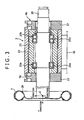
- each of the tire holding devices 3 is provided with a rim 28 to which the tire T is installed a spindle shaft (the horizontal shaft) 20 to be rotated integrally with this rim 28, a tubular housing 22 for rotatably supporting this spindle shaft 20, and a tubular housing holding member 23 for holding this housing 22.
- each of the left and right frame 7, 7 for supporting the tire holding devices 3 is provided with a pair of upper and lower first lateral members 14, two upper and lower second lateral members 18 provided between the upper and lower first lateral members 14 on the left or right side, a left or right vertical member 15 for coupling left outer ends or right outer ends of the first lateral members 14 and the second lateral members 18 in the up and down direction, and a left or right slide member 16 provided between the second lateral members 18 which are adjacent to each other in the up and down direction, the slide member being movable in the left and right direction relative to the second lateral members 18.
- the tire holding devices 3 are attached to the slide members 16 respectively.
- a pair of left and right actuators 17 for sliding the slide members 16 are fixed to the vertical members 15 and coupled to the slide members 16, respectively.
- the actuators 17 are extendable and contractible in the left and right direction, and the extension and contraction thereof moves the slide members 16 and the tire holding devices 3 supported on the slide members in the left and right direction relative to the second lateral members 18.
- the housing holding member 23 shown in Figs. 2 and 3 is fixed to the slide member 16 for holding the tubular housing 22.
- an axis of the housing 22 and an axis of the housing holding member 23 correspond to each other, and the housing 22 and the housing holding member 23 have substantially similar axial length.
- the spindle shaft 20 is inserted into the housing 22, and bearings (rolling bearings) 25a, 4b for rotatably supporting the spindle shaft 20 are provided between an outer peripheral surface of the spindle shaft 20 and an inner peripheral surface of the housing 22 so as to be spaced from each other in the front and rear direction.
- the bearings 25a, 25b the bearing 25a provided on the front end side of the spindle shaft 20 (the side in which the tire T is attached) is a roller bearing, and the bearing 25b provided on the base end side of the spindle shaft 20 is a ball bearing. Inner races of these beatings 25a, 25b are fixed to the spindle shaft 20, and outer races are fixed to the housing 22.
- the measurement device 4 has two load cells 4a, 4b (six-component gauges) capable of measuring a force and moment acting between the housing 22 and the housing holding member 23.
- the load cell 4a (the six-component gauge) is attached to a side surface of the housing 22 on the side in which the tire is attached
- the other load cell 4b (the six-component gauge) is attached to a side surface of the housing 22 on the opposite side to the side on which the tire is attached.
- These two load cells 4a, 4b sandwich the rolling bearings 25 for rotatably holding the spindle shaft 20 as described above from both the front and rear sides. With this structure, the measurement device 4 can measure the force and the moment generated in the spindle shaft.
- Each of the load cells 4a, 4b has a plurality of disc plate members 27 and a plurality of strain gauges (not shown).
- the plate members 27 are attached to longitudinal side surfaces of the housing 22 and the housing holding member 23 respectively and processed so that strain is locally concentrated in the pilate members due to the force acting between the housing 22 and the housing holding member 23.
- the strain gauges are adhered to surfaces of parts, respectively, of the plate members 27 where the strain is concentrated as described above, and electrically connected to a strain indicator (not shown.
- This strain indicator calculates a load (the force) and the moment in the X, Y, Z directions acting between the housing 22 and the housing holding member 23, according to a method known to those skilled in the art, based on output signals from the strain gauges.
- the X, Y, Z directions correspond to the directions of three-dimensional coordinate axes relative to the rotation center O of the tire T respectively
- the through direction indicates the X direction (the left and right direction in Figs. 1 , 2 )
- the left and right direction indicates the Y direction (the front and rear direction in Figs. 1 , 2 )
- the up and down direction indicates the Z direction (the up and down direction in Figs. 1 , 2 ).
- the force acting on the spindle shaft 20 is transmitted to the housing 22, and further transmitted to the plate members 27 sandwiched between this housing 22 and the housing holding member 23 fixed to the slide member 16.
- the force generated in the tire is transmitted to the spindle shaft 20, the bearings 25, the housing 22, and then the strain concentrated parts of the load cells 4a, 4b, and taken out as the signals of the strain gauges to be measured.
- a tire test in which a characteristic such as the rolling resistance of the tire is measured is based on the premise that a rotational torque is not imparted onto the center of the tire, that is, the tire is in a so-called state of freely rolling as described above. Meanwhile, the state that the rotational friction torque My1 generated at the time of rotating the spindle shaft 20 is imparted onto the spindle shaft 20 due to the impact of the bearings 25, the shaft sealing member, the lubricant oil and the like as described above is not the original state of freely rolling. That is, the rotational friction torque My1 received from the housing 22 in accordance with the rotation of the spindle shaft 20 becomes a cause of generating a measurement error.
- a torque canceller 5 for canceling the impact of the rotational friction torque My1 which the spindle shaft 20 receives from the housing 22 and the like as the spindle shaft rotates is further provided.
- Torque canceller 5 is provided with a rotational friction torque measuring unit for measuring the moment around the Y axis corresponding to the rotational friction torque My1, a motor 30 for the spindle shaft, and a control unit 32.
- the measurement device 4 also serves as the rotational friction torque measuring unit.
- the motor 30 for the spindle shaft is formed by a synchronous motor and imparts a predetermined torque My2 onto the spindle shaft 20 at the time of the tire test.
- the motor 30 for the spindle shaft is coupled to a base end of the spindle shaft 20 for applying the torque counteracting the rotational friction torque My1 due to rotational resistance and the like of the rolling bearings 25a, 25b onto the spindle shaft 20.
- the motor 30 for the spindle shaft imparts the torque My2 with the same magnitude as and in the opposite direction to the rotational friction torque My1 (the torque for cancelling the impact of the rotational friction torque My1 in the housing 22) onto the spindle shaft 20.
- the measurement device 4 measures the force and the moment acting between the housing 22 and the housing holding member 23 at the time of the tire test, and outputs measurement values thereof to the control unit 32.
- the moment around the Y axis corresponding to the rotational fiction torque My1 is outputted to the control unit 32 together with other measurement results.
- the control unit 32 controls the generated torque (the output torque) My2 outputted from the motor 30 for the spindle shaft.
- the control unit 32 controls the generated torque My2 of the motor 30 for the spindle shaft based on the rotational friction torque My1 which is the moment around the Y axis among the values measured by the measurement device 4.
- This adjustment is performed with, for example, inverter control (such as VVVF control of changing voltage, frequency and the like of the motor 30 for the spindle shaft.
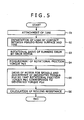
- Step S1 of Fig. 5 the actuator 17 is operated so as to move the tire holding device 3 in the direction in which the device 3 is brought close to the running drum 10. Since the tire T is pushed toward the pseudo-road surface R of this running drum 10, a predetermined load is imparted onto the tire T (Step S2). The drum motor 12 is operated while the load is imparted in such a way, so that the running drum 10 is rotated by predetermined rotation speed (Step S3).
- Step S4 the measurement device 4 measures the rotational friction torque My1 imparted onto the spindle shaft 20 (Step S4).
- the rotational friction torque My1 is imparted onto the center of the tire T.
- the measurement device 4 can determine a vertical load (a load reaction force) Fz in a state that the tire T contacts the pseudo-road surface R and a force Fx acting in the tire forward direction.
- a rolling radius in a state that the tire T runs and the like the rolling resistance of the tire T can be determined (S6).
- Methods for determining the rolling resistance of this tire T is the same as the conventional art and not particularly limited.
- the methods may include a method inputting various data such as the load (the force) in the X, Y, Z directions and the moment measured by the load cells and the rolling radius into a calculation device such as the control unit 32 and a computer (not shown) and determining the rolling resistance of the tire T by the calculation device from the various data, and other methods.
- a calculation device such as the control unit 32 and a computer (not shown) and determining the rolling resistance of the tire T by the calculation device from the various data, and other methods.
- the torque is imparted onto the spindle shaft 20 while adjusting the generated torque My2 of the motor 30 for the spindle shaft so that the rotational friction torque My1 corresponds to the generated torque My2 (so that a difference between the torques becomes zero). Therefore, the impact of the rotational friction torque My1 generated due to the rotational resistance and the like of the rolling bearings 25a, 25b at the time of running the tire on the measurement values is cancelled by the generated torque My2.
- the rotational friction torque My1 can be compensated and the spindle shaft 20 can be rotated in the state of freely rolling with no impact of the rotational friction torque My1 (in a state that the rotational friction torque My1 is not imparted onto the center of the tire T).
- the moment around the Y axis due to the fact that the spindle shaft 20 receives the impact from the bearings 25a, 25b, the shaft sealing member, the lubricant oil and the like, that is, the moment received in the housing in accordance with the rotation of the spindle shaft is eliminated. That is, the impact of the rotational friction torque My1 is cancelled, and torsion of the spindle shaft 20 due to the rotational friction torque My1 is eliminate.
- the measurement device 4 for measuring the force generated in the tire T also serves as the rotational friction torque measuring unit for measuring the rotational friction torque My1, the impact of the rotational friction torque My1 can be cancelled by a highly sample structure and control.
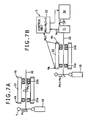
- Figs. 6 and 7 show a modified example of the torque canceller 5 of the tire testing machine 1 as a second embodiment of the present invention.
- Fig. 7(a) shows the rotational friction torque applied onto the spindle shaft
- Fig. 7(b) shows a relationship between the rotational friction torque and the generated torque and detected torque.
- the measurement device 4 serves also as the rotational friction torque measuring unit.
- the torque canceller 5 is provided with the rotational friction torque measuring unit, the motor 30 for the spindle shaft, a spindle shaft torque detecting unit 31, and a control unit 35. Since the measurement device 4 and the motor 30 for the spindle shaft are the same as the first embodiment, description thereof will be omitted.
- the spindle shaft torque detecting unit (a torque detection meter) 31 is arranged on the spindle shaft 20 (on the spindle shaft 20 between the housing 22 and the motor 30 for the spindle shaft) for detecting a torque My3 applied onto this spindle shaft 20 and outputting the torque to the control unit 32.
- the torque of the spindle shaft 20 detected by the spindle shaft torque detecting unit 31 is sometimes called as the detected torque My3.
- This spindle shaft torque detecting unit 31 may be built in the motor 30 for the spindle shaft.
- the control unit 35 controls the generate torque My2 of the motor 30 for the spindle shaft based on the rotational friction torque My1 measured by the measurement device 4 and the torque My3 detected by the spindle shaft torque detecting unit 31 at the time of rotating the tire T by the rotational force given from the running device 2.
- This adjustment is performed with, for example, the inverter control (such as the VVVF control) of changing the voltage, the frequency and the like of the motor 30 for the spindle shaft.
- Fig. 8 shows a method for testing the tire in the second embodiment. Steps S10 to S13 and S17 shown in Fig. 8 are the same as Steps S1 to 4 and S6 of Fig. 5 , respectively, according to the method for testing a tire of the first embodiment. Therefore, description thereof will be omitted.
- Step S14 of Fig. 8 the motor 30 for the spindle shaft is driven to rotate while generating the torque My2.
- the torque received by a shaft end of the spindle shaft 20 is measured by the spindle shaft torque detecting unit 31. as the detected torque My3 (Step S15).
- the torque canceller 5 is provided with the spindle shaft torque detecting unit 31 for detecting the torque applied onto the spindle shaft 20, and the control unit 32 for controlling the motor 30 for the spindle shaft based on the torque My3 detected by this spindle shaft torque detecting unit 31 and the rotational friction torque My1 received by the spindle shaft 20 which is measured by the measurement device 4. Therefore, the torque applied onto the spindle shaft 20 during the test of the tire T can be adjusted by feedback control, so that precision of the generated torque My2 for cancelling the rotational friction torque My1 can be improved.
- the present invention is not limited to the above embodiments as described below, for example.
- the rolling resistance is measured as the force generated in the tire in the above embodiments.
- an object to be measured is not limited.
- the tire testing machine and the method for testing the tire according, to the present invention can be applied to an object with measurement precision improved by eliminating the impact of the rotational friction torque received by the spindle shaft 20.
- the force generated in the tire T is measured when the tire T is rotated by the rotational force given from the running device.
- the force generated in the tire T may be measured in a state that the running device is brought apart from the tire T after contacting the tire T and giving the rotational force to the tire T, that is, in the state of freely rolling of the tire T.
- the moment around the Y axis generated in the spindle shaft 22 due to the impact of the bearings 25a, 25b, the shaft sealing member, the lubricant oil and the like is measured as the rotational friction torque My1.
- the rotational friction torque My1 since the impact of the moment due to rotational friction resistance of the bearings 25a, 25b is the largest, the rotational friction torque My1 may be regarded as the rotational friction resistance of the bearings.
- the rotational friction torque My1 of the spindle shaft 22 generated by the rotational friction resistance of the bearings 25a, 25b may be preliminarily determined by experiments, and this motor 30 for the spindle shaft may give the torque counteracting the rotational friction torque My1 to the spindle shaft 22.
- an exclusive torque meter for measuring the rotational friction torque My1 may be installed separately from the measurement device 4.
- the present invention is to provide the tire testing machine capable of measuring the force generated in the tire with high precision and the method for testing the tire.
- the tire testing machine according to the present invention includes the spindle shaft for holding the tire, the housing for rotatably supporting the spindle shaft through the bearing, the running device having the rotated running surface, the running device being adapted to give the rotational force to the tire contacting the running surface, the measurement device provided in the housing for measuring the force and the moment generated in the spindle shaft, and the torque canceller for canceling the impact of the rotational friction torque received by the spindle shaft from the housing in accordance with the rotation of the spindle shaft on the measurement.
- the torque canceller is, separately from the running device, provided with the spindle shaft torque imparter for imparting the torque for cancelling the impact of the rotational friction torque onto the spindle shaft.
- the measurement precision can be effectively improved by a simple structure in which the torque imparter imparts the torque for cancelling the impact of the rotational friction torque on the measurement to the spindle shaft separately from the running device.
- the torque canceller preferably includes the rotational friction torque measuring unit for measuring the rotational friction torque, and the control unit for controlling the generated torque of the motor for the spindle shaft based on the measured moment.
- the control unit may control the motor for the spindle shaft so that the rotational friction torque corresponds to the generated torque of the motor for the spindle shaft.
- the measurement device can serve also as the rotational friction torque measurement unit, and thereby the structure of the device can be simplified.
- the torque canceller is provided with the spindle shaft torque detecting unit for detecting the torque applied onto the spindle shaft, and the control unit controls the generated torque of the motor for the spindle shaft based on the moment corresponding to the rotational friction torque measured by the measurement device and the torque detected by the spindle shaft torque detecting unit, when the tire is rotated by the rotational force given by the running device.
- the control unit preferably controls the generated torque of the motor for the spindle shaft so that the difference between the moment corresponding to the rotational friction torque measured by the measurement device and the torque detected by the spindle shaft torque detecting unit becomes zero.
- the present invention is to provide the method for testing the tire of measuring the force generated in the tire with the tire testing machine including the spindle shaft for holding the tire, the housing for rotatably supporting this spindle shaft through the bearing, the running device having the surface rotated by rotational driving, the running device being adapted to give the rotational force to the tire abutting the surface, and the measurement device provided in the housing for measuring the force and the moment generated in the spindle shaft.
- the method is characterized by measuring the force generated in the tire while imparting the torque onto the spindle shaft separately from the running device so as to cancel the impact of the rotational friction torque received by the spindle shaft in the housing in accordance with the rotation of the spindle shaft.
- the moment corresponding to the rotational friction torque is measured and the torque applied onto the spindle shaft is separately detected, and the torque to be imparted onto the spindle is controlled so that the difference between the moment corresponding to the rotational friction torque and the detected torque becomes zero.
Priority Applications (2)
| Application Number | Priority Date | Filing Date | Title |
|---|---|---|---|
| PL09715420T PL2249138T3 (pl) | 2008-02-26 | 2009-02-24 | Maszyna testująca opony i sposób testowania opony |
| SI200930212T SI2249138T1 (sl) | 2008-02-26 | 2009-02-24 | Stroj za preizkušanje pnevmatik in postopek preizkušanja prevmatik |
Applications Claiming Priority (2)
| Application Number | Priority Date | Filing Date | Title |
|---|---|---|---|
| JP2008044183A JP4310365B1 (ja) | 2008-02-26 | 2008-02-26 | タイヤ試験機及びタイヤの試験方法 |
| PCT/JP2009/053266 WO2009107604A1 (ja) | 2008-02-26 | 2009-02-24 | タイヤ試験機及びタイヤの試験方法 |
Publications (3)
| Publication Number | Publication Date |
|---|---|
| EP2249138A1 EP2249138A1 (en) | 2010-11-10 |
| EP2249138A4 EP2249138A4 (en) | 2011-05-04 |
| EP2249138B1 true EP2249138B1 (en) | 2012-02-15 |
Family
ID=41015998
Family Applications (1)
| Application Number | Title | Priority Date | Filing Date |
|---|---|---|---|
| EP09715420A Active EP2249138B1 (en) | 2008-02-26 | 2009-02-24 | Tire testing machine and method for testing tire |
Country Status (12)
| Country | Link |
|---|---|
| US (1) | US8136393B2 (zh) |
| EP (1) | EP2249138B1 (zh) |
| JP (1) | JP4310365B1 (zh) |
| KR (1) | KR101209414B1 (zh) |
| CN (1) | CN101960281B (zh) |
| AT (1) | ATE545854T1 (zh) |
| ES (1) | ES2379857T3 (zh) |
| PL (1) | PL2249138T3 (zh) |
| PT (1) | PT2249138E (zh) |
| SI (1) | SI2249138T1 (zh) |
| TW (1) | TW200944770A (zh) |
| WO (1) | WO2009107604A1 (zh) |
Families Citing this family (25)
| Publication number | Priority date | Publication date | Assignee | Title |
|---|---|---|---|---|
| KR101114160B1 (ko) * | 2007-03-30 | 2012-03-14 | 혼다 기켄 고교 가부시키가이샤 | 타이어 구동 전달 효율 측정 장치, 타이어 구동 전달 효율 측정 방법 및 예측 연비의 산출 방법 |
| JP5179999B2 (ja) * | 2008-08-12 | 2013-04-10 | 株式会社神戸製鋼所 | タイヤ試験機の駆動制御方法及びタイヤ試験機 |
| JP5001345B2 (ja) * | 2009-12-16 | 2012-08-15 | 株式会社小野測器 | タイヤ試験装置 |
| US20110238483A1 (en) * | 2010-03-29 | 2011-09-29 | Boku, Inc. | Systems and Methods to Distribute and Redeem Offers |
| US9038449B2 (en) | 2010-04-16 | 2015-05-26 | Camber Ridge, Llc | Tire testing systems and methods |
| TWI414060B (zh) | 2010-09-17 | 2013-11-01 | Kingpak Tech Inc | 模造成型之免調焦距影像感測器構裝結構及其製造方法 |
| JP5191521B2 (ja) * | 2010-10-05 | 2013-05-08 | 株式会社神戸製鋼所 | タイヤ試験機に用いられる多分力計測スピンドルユニットの校正方法 |
| JP5225367B2 (ja) | 2010-12-15 | 2013-07-03 | 株式会社神戸製鋼所 | 転がり抵抗試験機に備えられた多分力検出器の校正方法 |
| JP5225370B2 (ja) * | 2010-12-24 | 2013-07-03 | 株式会社神戸製鋼所 | 転がり抵抗試験機に備えられた多分力検出器の校正方法 |
| WO2013040148A2 (en) * | 2011-09-13 | 2013-03-21 | Camber Ridge, Llc | Tire testing systems and methods |
| US9360396B2 (en) * | 2011-10-06 | 2016-06-07 | Kobe Steel, Ltd. | Tire uniformity testing device and tire uniformity testing method |
| CN104010835B (zh) * | 2011-12-29 | 2017-10-10 | 米其林集团总公司 | 用于轮胎测试行走轮的轮胎操作表面 |
| JP5784533B2 (ja) * | 2012-03-22 | 2015-09-24 | 株式会社神戸製鋼所 | タイヤ試験機の多分力計測スピンドルユニット |
| US8910512B2 (en) * | 2012-03-22 | 2014-12-16 | Kobe Steel, Ltd. | Multi-component force measurement spindle unit of tire testing machine |
| ITBO20120286A1 (it) * | 2012-05-24 | 2013-11-25 | Aerre S R L | Dispositivo per il controllo della geometria di uno pneumatico |
| JP5843706B2 (ja) * | 2012-06-20 | 2016-01-13 | 株式会社神戸製鋼所 | 転がり抵抗試験機に備えられた多分力検出器の校正方法 |
| EP2713153A3 (en) | 2012-09-30 | 2016-08-17 | Michelin Recherche et Technique S.A. | Method of applying particulate material along a tire footprint during tire testing on a tire testing surface |
| CN108663147B (zh) * | 2012-10-12 | 2023-05-12 | 国际计测器株式会社 | 转矩赋予单元、驱动装置和轮胎测试装置 |
| EP2914947B1 (en) | 2012-10-31 | 2018-02-28 | Compagnie Générale des Etablissements Michelin | Method and apparatus for distributing particulate material along a tire footprint during tire testing |
| WO2017199467A1 (ja) * | 2016-05-20 | 2017-11-23 | 株式会社Ihi | タイヤ試験装置 |
| JP7265790B2 (ja) * | 2018-04-20 | 2023-04-27 | 国際計測器株式会社 | タイヤ試験装置 |
| RU2682806C1 (ru) * | 2018-05-22 | 2019-03-21 | федеральное государственное бюджетное образовательное учреждение высшего образования "Национальный исследовательский университет "МЭИ" (ФГБОУ ВО "НИУ "МЭИ") | Энергосберегающий электропривод для стенда испытаний тракторных шин |
| CN110927056B (zh) * | 2019-12-25 | 2022-05-17 | 中国航空工业集团公司西安飞机设计研究所 | 一种轴承内圈与螺栓表面的摩擦系数测量装置和测量方法 |
| CN110927057B (zh) * | 2019-12-25 | 2022-05-13 | 中国航空工业集团公司西安飞机设计研究所 | 轴承内圈端面与衬套表面的摩擦系数测量装置和测量方法 |
| JP7303375B2 (ja) | 2020-04-06 | 2023-07-04 | 三菱重工機械システム株式会社 | 転がり抵抗測定装置、転がり抵抗測定方法及びプログラム |
Family Cites Families (9)
| Publication number | Priority date | Publication date | Assignee | Title |
|---|---|---|---|---|
| US3948080A (en) * | 1974-09-03 | 1976-04-06 | The United States Of America As Represented By The Secretary Of The Department Of Transportation | Apparatus for testing the traction properties of pneumatic tires |
| US4479382A (en) * | 1982-04-05 | 1984-10-30 | The Goodyear Tire & Rubber Company | System for testing a tire to avoid a torque steer effect |
| US4576040A (en) | 1983-06-29 | 1986-03-18 | Eagle-Picher Industries, Inc. | Device for measuring extraneous losses in apparatus for measuring the rolling resistance of tires |
| US5481907A (en) * | 1993-12-13 | 1996-01-09 | Mts Systems Corporation | Tire testing system having focused links reducing cosine errors |
| JPH09183544A (ja) | 1995-12-28 | 1997-07-15 | Kawasaki Steel Corp | シート巻取り制御における機械損失補償方法 |
| JP4817213B2 (ja) * | 2001-04-20 | 2011-11-16 | 日章電機株式会社 | タイヤのころがり抵抗測定方法および装置 |
| JP4114044B2 (ja) * | 2001-07-17 | 2008-07-09 | トヨタ自動車株式会社 | タイヤ作用力検出装置 |
| JP5403952B2 (ja) * | 2008-06-11 | 2014-01-29 | 株式会社神戸製鋼所 | タイヤ試験機及びタイヤ試験方法 |
| US7908917B2 (en) * | 2008-08-12 | 2011-03-22 | Kobe Steel, Ltd. | Driving control method of tire testing machine and tire testing machine |
-
2008
- 2008-02-26 JP JP2008044183A patent/JP4310365B1/ja not_active Expired - Fee Related
-
2009
- 2009-02-24 US US12/919,027 patent/US8136393B2/en not_active Expired - Fee Related
- 2009-02-24 SI SI200930212T patent/SI2249138T1/sl unknown
- 2009-02-24 KR KR1020107018834A patent/KR101209414B1/ko active IP Right Grant
- 2009-02-24 ES ES09715420T patent/ES2379857T3/es active Active
- 2009-02-24 PT PT09715420T patent/PT2249138E/pt unknown
- 2009-02-24 CN CN2009801063927A patent/CN101960281B/zh not_active Expired - Fee Related
- 2009-02-24 AT AT09715420T patent/ATE545854T1/de active
- 2009-02-24 PL PL09715420T patent/PL2249138T3/pl unknown
- 2009-02-24 EP EP09715420A patent/EP2249138B1/en active Active
- 2009-02-24 WO PCT/JP2009/053266 patent/WO2009107604A1/ja active Application Filing
- 2009-02-26 TW TW098106221A patent/TW200944770A/zh not_active IP Right Cessation
Also Published As
| Publication number | Publication date |
|---|---|
| CN101960281A (zh) | 2011-01-26 |
| KR101209414B1 (ko) | 2012-12-06 |
| CN101960281B (zh) | 2012-09-19 |
| EP2249138A1 (en) | 2010-11-10 |
| JP2009204324A (ja) | 2009-09-10 |
| KR20100110879A (ko) | 2010-10-13 |
| PT2249138E (pt) | 2012-05-02 |
| EP2249138A4 (en) | 2011-05-04 |
| SI2249138T1 (sl) | 2012-05-31 |
| TWI378232B (zh) | 2012-12-01 |
| PL2249138T3 (pl) | 2012-07-31 |
| ATE545854T1 (de) | 2012-03-15 |
| TW200944770A (en) | 2009-11-01 |
| US20110000292A1 (en) | 2011-01-06 |
| JP4310365B1 (ja) | 2009-08-05 |
| ES2379857T3 (es) | 2012-05-04 |
| US8136393B2 (en) | 2012-03-20 |
| WO2009107604A1 (ja) | 2009-09-03 |
Similar Documents
| Publication | Publication Date | Title |
|---|---|---|
| EP2249138B1 (en) | Tire testing machine and method for testing tire | |
| US9791344B2 (en) | Calibration method for multi-component force detector provided in rolling resistance testing machine | |
| EP2536578B1 (en) | Tire changer and method of measuring force variations acting between a roller and a tread surface of a tyre/wheel assembly | |
| US7934421B2 (en) | Biaxial wheel test assembly | |
| KR101505345B1 (ko) | 구름 저항 시험기에 구비된 다분력 검출기의 교정 방법 | |
| EP2543980B1 (en) | Wheel balancer with means for determining tyre uniformity | |
| EP2762853A1 (en) | Torsion test device | |
| WO2009152129A1 (en) | Flat belt roadway simulator with steer and/or camber adjustment and method for ascertaining rolling loss | |
| JP4616212B2 (ja) | 車両振動計測装置および車両振動計測方法 | |
| WO2009116513A1 (ja) | タイヤ試験機及びタイヤ試験方法 | |
| JP2008216189A (ja) | 車両試験装置 | |
| JP2007078477A (ja) | ホイ−ルアライメント測定方法およびその測定装置 | |
| JPH06331505A (ja) | 車両片流れ評価装置 | |
| CN110476048B (zh) | 旋转体载荷测量装置 | |
| CN110612438B (zh) | 旋转体载荷测量装置 | |
| JP2005315882A (ja) | 車両のホイールアライメント調整方法 | |
| JP2009042170A (ja) | シャシーダイナモメータの検量装置 | |
| KR20070039650A (ko) | 차량의 차륜정렬장치 |
Legal Events
| Date | Code | Title | Description |
|---|---|---|---|
| PUAI | Public reference made under article 153(3) epc to a published international application that has entered the european phase |
Free format text: ORIGINAL CODE: 0009012 |
|
| 17P | Request for examination filed |
Effective date: 20100818 |
|
| AK | Designated contracting states |
Kind code of ref document: A1 Designated state(s): AT BE BG CH CY CZ DE DK EE ES FI FR GB GR HR HU IE IS IT LI LT LU LV MC MK MT NL NO PL PT RO SE SI SK TR |
|
| AX | Request for extension of the european patent |
Extension state: AL BA RS |
|
| A4 | Supplementary search report drawn up and despatched |
Effective date: 20110331 |
|
| DAX | Request for extension of the european patent (deleted) | ||
| RIC1 | Information provided on ipc code assigned before grant |
Ipc: G01M 17/02 20060101AFI20110527BHEP Ipc: B60C 19/00 20060101ALI20110527BHEP |
|
| GRAP | Despatch of communication of intention to grant a patent |
Free format text: ORIGINAL CODE: EPIDOSNIGR1 |
|
| RIN1 | Information on inventor provided before grant (corrected) |
Inventor name: YOSHIKAWA, TETSUYAC/O TAKASAGO WORKS IN KOBE STEEL Inventor name: FUJIEDA, YASUHIKOC/O TAKASAGO WORKS IN KOBE STEEL, |
|
| GRAS | Grant fee paid |
Free format text: ORIGINAL CODE: EPIDOSNIGR3 |
|
| GRAA | (expected) grant |
Free format text: ORIGINAL CODE: 0009210 |
|
| AK | Designated contracting states |
Kind code of ref document: B1 Designated state(s): AT BE BG CH CY CZ DE DK EE ES FI FR GB GR HR HU IE IS IT LI LT LU LV MC MK MT NL NO PL PT RO SE SI SK TR |
|
| REG | Reference to a national code |
Ref country code: CH Ref legal event code: EP Ref country code: GB Ref legal event code: FG4D |
|
| REG | Reference to a national code |
Ref country code: IE Ref legal event code: FG4D |
|
| REG | Reference to a national code |
Ref country code: AT Ref legal event code: REF Ref document number: 545854 Country of ref document: AT Kind code of ref document: T Effective date: 20120315 |
|
| REG | Reference to a national code |
Ref country code: DE Ref legal event code: R096 Ref document number: 602009005352 Country of ref document: DE Effective date: 20120412 |
|
| REG | Reference to a national code |
Ref country code: RO Ref legal event code: EPE |
|
| REG | Reference to a national code |
Ref country code: PT Ref legal event code: SC4A Free format text: AVAILABILITY OF NATIONAL TRANSLATION Effective date: 20120417 |
|
| REG | Reference to a national code |
Ref country code: ES Ref legal event code: FG2A Ref document number: 2379857 Country of ref document: ES Kind code of ref document: T3 Effective date: 20120504 |
|
| REG | Reference to a national code |
Ref country code: NL Ref legal event code: T3 |
|
| REG | Reference to a national code |
Ref country code: SK Ref legal event code: T3 Ref document number: E 11609 Country of ref document: SK |
|
| LTIE | Lt: invalidation of european patent or patent extension |
Effective date: 20120215 |
|
| PG25 | Lapsed in a contracting state [announced via postgrant information from national office to epo] |
Ref country code: IS Free format text: LAPSE BECAUSE OF FAILURE TO SUBMIT A TRANSLATION OF THE DESCRIPTION OR TO PAY THE FEE WITHIN THE PRESCRIBED TIME-LIMIT Effective date: 20120615 Ref country code: HR Free format text: LAPSE BECAUSE OF FAILURE TO SUBMIT A TRANSLATION OF THE DESCRIPTION OR TO PAY THE FEE WITHIN THE PRESCRIBED TIME-LIMIT Effective date: 20120215 Ref country code: NO Free format text: LAPSE BECAUSE OF FAILURE TO SUBMIT A TRANSLATION OF THE DESCRIPTION OR TO PAY THE FEE WITHIN THE PRESCRIBED TIME-LIMIT Effective date: 20120515 Ref country code: LT Free format text: LAPSE BECAUSE OF FAILURE TO SUBMIT A TRANSLATION OF THE DESCRIPTION OR TO PAY THE FEE WITHIN THE PRESCRIBED TIME-LIMIT Effective date: 20120215 |
|
| REG | Reference to a national code |
Ref country code: PL Ref legal event code: T3 |
|
| PG25 | Lapsed in a contracting state [announced via postgrant information from national office to epo] |
Ref country code: BE Free format text: LAPSE BECAUSE OF FAILURE TO SUBMIT A TRANSLATION OF THE DESCRIPTION OR TO PAY THE FEE WITHIN THE PRESCRIBED TIME-LIMIT Effective date: 20120215 Ref country code: LV Free format text: LAPSE BECAUSE OF FAILURE TO SUBMIT A TRANSLATION OF THE DESCRIPTION OR TO PAY THE FEE WITHIN THE PRESCRIBED TIME-LIMIT Effective date: 20120215 Ref country code: GR Free format text: LAPSE BECAUSE OF FAILURE TO SUBMIT A TRANSLATION OF THE DESCRIPTION OR TO PAY THE FEE WITHIN THE PRESCRIBED TIME-LIMIT Effective date: 20120516 |
|
| REG | Reference to a national code |
Ref country code: AT Ref legal event code: MK05 Ref document number: 545854 Country of ref document: AT Kind code of ref document: T Effective date: 20120215 |
|
| PG25 | Lapsed in a contracting state [announced via postgrant information from national office to epo] |
Ref country code: CY Free format text: LAPSE BECAUSE OF FAILURE TO SUBMIT A TRANSLATION OF THE DESCRIPTION OR TO PAY THE FEE WITHIN THE PRESCRIBED TIME-LIMIT Effective date: 20120215 Ref country code: MC Free format text: LAPSE BECAUSE OF NON-PAYMENT OF DUE FEES Effective date: 20120229 |
|
| REG | Reference to a national code |
Ref country code: HU Ref legal event code: AG4A Ref document number: E013907 Country of ref document: HU |
|
| PG25 | Lapsed in a contracting state [announced via postgrant information from national office to epo] |
Ref country code: EE Free format text: LAPSE BECAUSE OF FAILURE TO SUBMIT A TRANSLATION OF THE DESCRIPTION OR TO PAY THE FEE WITHIN THE PRESCRIBED TIME-LIMIT Effective date: 20120215 Ref country code: DK Free format text: LAPSE BECAUSE OF FAILURE TO SUBMIT A TRANSLATION OF THE DESCRIPTION OR TO PAY THE FEE WITHIN THE PRESCRIBED TIME-LIMIT Effective date: 20120215 Ref country code: SE Free format text: LAPSE BECAUSE OF FAILURE TO SUBMIT A TRANSLATION OF THE DESCRIPTION OR TO PAY THE FEE WITHIN THE PRESCRIBED TIME-LIMIT Effective date: 20120215 |
|
| REG | Reference to a national code |
Ref country code: IE Ref legal event code: MM4A |
|
| PLBE | No opposition filed within time limit |
Free format text: ORIGINAL CODE: 0009261 |
|
| STAA | Information on the status of an ep patent application or granted ep patent |
Free format text: STATUS: NO OPPOSITION FILED WITHIN TIME LIMIT |
|
| 26N | No opposition filed |
Effective date: 20121116 |
|
| PG25 | Lapsed in a contracting state [announced via postgrant information from national office to epo] |
Ref country code: AT Free format text: LAPSE BECAUSE OF FAILURE TO SUBMIT A TRANSLATION OF THE DESCRIPTION OR TO PAY THE FEE WITHIN THE PRESCRIBED TIME-LIMIT Effective date: 20120215 Ref country code: IE Free format text: LAPSE BECAUSE OF NON-PAYMENT OF DUE FEES Effective date: 20120224 |
|
| PG25 | Lapsed in a contracting state [announced via postgrant information from national office to epo] |
Ref country code: MK Free format text: LAPSE BECAUSE OF FAILURE TO SUBMIT A TRANSLATION OF THE DESCRIPTION OR TO PAY THE FEE WITHIN THE PRESCRIBED TIME-LIMIT Effective date: 20120215 |
|
| REG | Reference to a national code |
Ref country code: DE Ref legal event code: R097 Ref document number: 602009005352 Country of ref document: DE Effective date: 20121116 |
|
| PG25 | Lapsed in a contracting state [announced via postgrant information from national office to epo] |
Ref country code: MT Free format text: LAPSE BECAUSE OF FAILURE TO SUBMIT A TRANSLATION OF THE DESCRIPTION OR TO PAY THE FEE WITHIN THE PRESCRIBED TIME-LIMIT Effective date: 20120215 |
|
| REG | Reference to a national code |
Ref country code: CH Ref legal event code: PL |
|
| PG25 | Lapsed in a contracting state [announced via postgrant information from national office to epo] |
Ref country code: LI Free format text: LAPSE BECAUSE OF NON-PAYMENT OF DUE FEES Effective date: 20130228 Ref country code: CH Free format text: LAPSE BECAUSE OF NON-PAYMENT OF DUE FEES Effective date: 20130228 |
|
| REG | Reference to a national code |
Ref country code: FR Ref legal event code: PLFP Year of fee payment: 8 |
|
| REG | Reference to a national code |
Ref country code: FR Ref legal event code: PLFP Year of fee payment: 9 |
|
| REG | Reference to a national code |
Ref country code: FR Ref legal event code: PLFP Year of fee payment: 10 |
|
| PGFP | Annual fee paid to national office [announced via postgrant information from national office to epo] |
Ref country code: BG Payment date: 20191217 Year of fee payment: 12 |
|
| PGFP | Annual fee paid to national office [announced via postgrant information from national office to epo] |
Ref country code: PL Payment date: 20191216 Year of fee payment: 12 |
|
| PGFP | Annual fee paid to national office [announced via postgrant information from national office to epo] |
Ref country code: PT Payment date: 20200224 Year of fee payment: 12 Ref country code: NL Payment date: 20200212 Year of fee payment: 12 Ref country code: GB Payment date: 20200212 Year of fee payment: 12 Ref country code: FI Payment date: 20200210 Year of fee payment: 12 Ref country code: ES Payment date: 20200302 Year of fee payment: 12 Ref country code: IT Payment date: 20200128 Year of fee payment: 12 Ref country code: HU Payment date: 20200124 Year of fee payment: 12 Ref country code: RO Payment date: 20200116 Year of fee payment: 12 Ref country code: DE Payment date: 20200211 Year of fee payment: 12 |
|
| PGFP | Annual fee paid to national office [announced via postgrant information from national office to epo] |
Ref country code: CZ Payment date: 20200129 Year of fee payment: 12 Ref country code: SI Payment date: 20200122 Year of fee payment: 12 Ref country code: LU Payment date: 20200210 Year of fee payment: 12 Ref country code: SK Payment date: 20200127 Year of fee payment: 12 |
|
| PGFP | Annual fee paid to national office [announced via postgrant information from national office to epo] |
Ref country code: FR Payment date: 20200113 Year of fee payment: 12 |
|
| REG | Reference to a national code |
Ref country code: DE Ref legal event code: R119 Ref document number: 602009005352 Country of ref document: DE |
|
| REG | Reference to a national code |
Ref country code: FI Ref legal event code: MAE |
|
| GBPC | Gb: european patent ceased through non-payment of renewal fee |
Effective date: 20210224 |
|
| REG | Reference to a national code |
Ref country code: SK Ref legal event code: MM4A Ref document number: E 11609 Country of ref document: SK Effective date: 20210224 |
|
| PG25 | Lapsed in a contracting state [announced via postgrant information from national office to epo] |
Ref country code: HU Free format text: LAPSE BECAUSE OF NON-PAYMENT OF DUE FEES Effective date: 20210225 Ref country code: BG Free format text: LAPSE BECAUSE OF NON-PAYMENT OF DUE FEES Effective date: 20210831 Ref country code: LU Free format text: LAPSE BECAUSE OF NON-PAYMENT OF DUE FEES Effective date: 20210224 Ref country code: CZ Free format text: LAPSE BECAUSE OF NON-PAYMENT OF DUE FEES Effective date: 20210224 Ref country code: FI Free format text: LAPSE BECAUSE OF NON-PAYMENT OF DUE FEES Effective date: 20210224 |
|
| PG25 | Lapsed in a contracting state [announced via postgrant information from national office to epo] |
Ref country code: RO Free format text: LAPSE BECAUSE OF NON-PAYMENT OF DUE FEES Effective date: 20210224 Ref country code: SK Free format text: LAPSE BECAUSE OF NON-PAYMENT OF DUE FEES Effective date: 20210224 Ref country code: PT Free format text: LAPSE BECAUSE OF NON-PAYMENT OF DUE FEES Effective date: 20210824 |
|
| REG | Reference to a national code |
Ref country code: NL Ref legal event code: MM Effective date: 20210301 |
|
| PG25 | Lapsed in a contracting state [announced via postgrant information from national office to epo] |
Ref country code: NL Free format text: LAPSE BECAUSE OF NON-PAYMENT OF DUE FEES Effective date: 20210301 |
|
| PG25 | Lapsed in a contracting state [announced via postgrant information from national office to epo] |
Ref country code: DE Free format text: LAPSE BECAUSE OF NON-PAYMENT OF DUE FEES Effective date: 20210901 Ref country code: GB Free format text: LAPSE BECAUSE OF NON-PAYMENT OF DUE FEES Effective date: 20210224 Ref country code: FR Free format text: LAPSE BECAUSE OF NON-PAYMENT OF DUE FEES Effective date: 20210228 |
|
| REG | Reference to a national code |
Ref country code: SI Ref legal event code: KO00 Effective date: 20211129 |
|
| PG25 | Lapsed in a contracting state [announced via postgrant information from national office to epo] |
Ref country code: SI Free format text: LAPSE BECAUSE OF NON-PAYMENT OF DUE FEES Effective date: 20210225 |
|
| PG25 | Lapsed in a contracting state [announced via postgrant information from national office to epo] |
Ref country code: IT Free format text: LAPSE BECAUSE OF NON-PAYMENT OF DUE FEES Effective date: 20210224 |
|
| REG | Reference to a national code |
Ref country code: ES Ref legal event code: FD2A Effective date: 20220513 |
|
| PGFP | Annual fee paid to national office [announced via postgrant information from national office to epo] |
Ref country code: TR Payment date: 20220222 Year of fee payment: 14 |
|
| PG25 | Lapsed in a contracting state [announced via postgrant information from national office to epo] |
Ref country code: ES Free format text: LAPSE BECAUSE OF NON-PAYMENT OF DUE FEES Effective date: 20210225 |
|
| PG25 | Lapsed in a contracting state [announced via postgrant information from national office to epo] |
Ref country code: PL Free format text: LAPSE BECAUSE OF NON-PAYMENT OF DUE FEES Effective date: 20210224 |