US4576040A - Device for measuring extraneous losses in apparatus for measuring the rolling resistance of tires - Google Patents
Device for measuring extraneous losses in apparatus for measuring the rolling resistance of tires Download PDFInfo
- Publication number
- US4576040A US4576040A US06/508,939 US50893983A US4576040A US 4576040 A US4576040 A US 4576040A US 50893983 A US50893983 A US 50893983A US 4576040 A US4576040 A US 4576040A
- Authority
- US
- United States
- Prior art keywords
- tire
- bearing housing
- measuring
- rolling resistance
- housing
- Prior art date
- Legal status (The legal status is an assumption and is not a legal conclusion. Google has not performed a legal analysis and makes no representation as to the accuracy of the status listed.)
- Expired - Lifetime
Links
Images

Classifications
-
- G—PHYSICS
- G01—MEASURING; TESTING
- G01M—TESTING STATIC OR DYNAMIC BALANCE OF MACHINES OR STRUCTURES; TESTING OF STRUCTURES OR APPARATUS, NOT OTHERWISE PROVIDED FOR
- G01M17/00—Testing of vehicles
- G01M17/007—Wheeled or endless-tracked vehicles
- G01M17/02—Tyres
- G01M17/022—Tyres the tyre co-operating with rotatable rolls
Definitions
- This invention relates to apparatus for measuring the rolling resistance of tires, and more particularly, the invention relates to a device for improving the accuracy of the measurement of the rolling resistance.
- the apparatus for measuring the rolling resistance of a tire consists of a rotatable road wheel (although it could be a flat belt as shown in U.S. Pat. No. 4,458,527) and a mechanism for pressing a tire against the road wheel at a loading which would be typical for a tire mounted on a vehicle.
- the road wheel is rotated at a desired speed or speeds to simulate a tire rolling over a highway.
- a mechanism is provided to measure the force required to rotate the wheel.
- the tire may, for example, be mounted on a floating frame and a load cell located adjacent the interface between the tire and the road wheel resists the movement of the support and provides a measure of the force tending to move the support.
- Such a device provides an approximation of the rolling resistance of the tire, but that measurement would include extraneous losses due to the tire spindle bearings, rotating air unions for slip rings for tire instrumentation.
- a common method used to correct for the extraneous losses has been to load the tire to a lighter load, for example 10% of test load or less, and use the rolling resistance measurement at the light load to correct the measurement made at the test load. This too provides only an approximation since extraneous losses are to some extent a function of the actual test load.
- An objective of the present invention is to provide a mechanism for directly measuring the extraneous losses so that they can be subtracted either electronically or arithmetically from the measured rolling resistance under a test load, thereby providing a more accurate measurement of the actual rolling resistance of the tires.
- the objective of the invention is attained by providing a hydrostatic bearing and a load cell located between the tire spindle and the platform on which it is supported. More specifically, an outer bearing housing is fixed to the platform which carries the tire. An inner bearing housing is mounted by means of a hydrostatic bearing to the outer bearing housing. The spindle which carries the tire is mounted by conventional bearings to the inner bearing housing. The load cell is connected between the inner bearing housing and the platform to block rotation of the inner bearing housing with respect to the outer bearing housing and thus to provide a measurement of the drag forces (extraneous losses) created by the bearings, air union and slip rings for measurement instrumentation. Stated another way, a torque tending to rotate the inner bearing housing is created by the drag forces as the spindle rotates and the load cell measures that torque which can thereafter be subtracted from the actual rolling resistance measurement which is a combination of the tire rolling resistance and the torque.
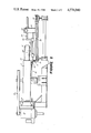
- FIG. 1 is a plan view of apparatus for measuring the rolling resistance of tires
- FIG. 2 is a side elevation view of that apparatus as seen in the direction of lines 2--2 of FIG. 1;
- FIG. 3 is a cross-sectional view taken along lines 3--3 of FIG. 1.
- the apparatus includes a base 10 on which a road wheel 11 is rotatably mounted.
- the road wheel is driven by a motor 12 through a belt and pulley system 13.
- a tire 15 is rotatably mounted adjacent the road wheel and pressed against it to simulate a tire rolling over a highway.
- the tire is mounted to the base as follows: a platform 20 is slidably mounted to the base by oil bearing 21. Within limits the platform can slide, substantially frictionlessly, in any horizontal direction.
- a carriage 22 is slidably mounted on the platform.
- a spindle 25 is rotatably mounted on the carriage and supports the tire 15.
- the carriage has a vertically-projecting bracket 26.
- a frame 27 is mounted on the platform 20 and carries a motor 28 to drive a ball screw 29 located between the frame and the bracket 26.
- Rotation of the ball screw 29 causes the carriage 22 and hence the tire 15 to move toward the road wheel, thus loading the tire against the road wheel to simulate actual running conditions.
- the reaction to the force of the tire on the road wheel is resisted by a radial linkage 32 connected between the platform 20 and the base 10.
- the radial linkage includes a load cell 33 by which the force of the tire on the road wheel is measured.
- a load cell 31 which is connected between the floating platform 20 and the base.
- the force measured by the load cell also includes the drag forces within the bearing system which supports the spindle. Those drag forces are measured by the apparatus of the present invention which can be best comprehended by reference to FIG. 3.
- an outer bearing housing 40 of the spindle 25 is mounted on the carriage 22.
- An inner bearing housing 41 is rotatably mounted in the outer bearing housing by means of a hydrostatic bearing created by supplying oil through a port 42 between the surfaces 43 and 44 of the outer and inner bearings, respectively.
- a hollow spindle shaft 45 is mounted by conventional roller or ball bearings 46 to the inner bearing housing, the assembly being secured by a bearing nut 47.
- a rotating air union 48 is coupled to the spindle to supply air to the spindle through a port 49. The air is supplied to the spindle to inflate the tire and maintain it inflated at the desired pressure.
- a slip ring assembly 55 is mounted on the spindle and projects through the rotating air union.
- the slip ring assembly can be connected to a variety of transducers associated with the tire to measure parameters such as temperature and pressure.
- a post 56 depends from the inner bearing housing, and the port 49 as well as the instrumentation wires 57 for the slip ring assembly are strapped to the post.
- the connections to the air port 49 and the instrumentation wires 57 should be loose so as not to introduce any significant force tending to restrain rotation of the inner bearing housing.
- An arm 60 is fixed to the inner bearing housing and projects through a bore 61 of substantially greater dimension than that of the arm 60 so that the inner bearing housing is free to rotate slightly with respect to the outer bearing housing.
- a load cell 65 is connected between the arm 60 and the floating platform 20 to resist the tendency of the inner bearing housing to rotate and to measure the forces tending to rotate it, those forces being the extraneous losses arising from the bearings, the rotating union and the slip ring assembly.
- the tire is inflated to the desired pressure, preferably that which would occur under normal road conditions when the tire has been heated due to its rolling resistance.
- the tire is pressed against the rotating road wheel 11.
- the rotating road wheel tends to drive the tire and its floating platform 20 laterally. That force is resisted by the load cell 31, and the force which the load cell measures is the combination of the tire rolling resistance and the drag forces associated with the spindle.
Abstract
Description
Claims (3)
Priority Applications (2)
| Application Number | Priority Date | Filing Date | Title |
|---|---|---|---|
| US06/508,939 US4576040A (en) | 1983-06-29 | 1983-06-29 | Device for measuring extraneous losses in apparatus for measuring the rolling resistance of tires |
| JP59056426A JPS6011134A (en) | 1983-06-29 | 1984-03-26 | Measuring device for rolling resistance of tire |
Applications Claiming Priority (1)
| Application Number | Priority Date | Filing Date | Title |
|---|---|---|---|
| US06/508,939 US4576040A (en) | 1983-06-29 | 1983-06-29 | Device for measuring extraneous losses in apparatus for measuring the rolling resistance of tires |
Publications (1)
| Publication Number | Publication Date |
|---|---|
| US4576040A true US4576040A (en) | 1986-03-18 |
Family
ID=24024676
Family Applications (1)
| Application Number | Title | Priority Date | Filing Date |
|---|---|---|---|
| US06/508,939 Expired - Lifetime US4576040A (en) | 1983-06-29 | 1983-06-29 | Device for measuring extraneous losses in apparatus for measuring the rolling resistance of tires |
Country Status (2)
| Country | Link |
|---|---|
| US (1) | US4576040A (en) |
| JP (1) | JPS6011134A (en) |
Cited By (9)
| Publication number | Priority date | Publication date | Assignee | Title |
|---|---|---|---|---|
| US5979231A (en) * | 1997-01-24 | 1999-11-09 | Illinois Tool Works, Inc. | Loadwheel assembly for tire testing systems having conical support plates |
| US5992227A (en) * | 1997-01-24 | 1999-11-30 | Jellison; Frank R. | Automatic adjustable width chuck apparatus for tire testing systems |
| US6016695A (en) * | 1997-01-24 | 2000-01-25 | Illinois Tool Works Inc. | Tire uniformity testing system |
| US6082191A (en) * | 1997-01-24 | 2000-07-04 | Illinois Tool Works, Inc. | Inlet conveyor for tire testing systems |
| US6584835B2 (en) * | 2000-02-11 | 2003-07-01 | Mts Systems Corporation | Spindle assembly for a tire or wheel testing machine |
| US6834559B1 (en) | 1999-07-09 | 2004-12-28 | Illinois Tool Works Inc. | Vibration compensation system for tire testing systems |
| US20110000292A1 (en) * | 2008-02-26 | 2011-01-06 | Kabushiki Kaisha Kobe Seiko Sho (Kobe Steel, Ltd.) | Tire testing machine and method for testing tire |
| CN103759954A (en) * | 2014-02-25 | 2014-04-30 | 吉林大学 | Method and device for precisely testing rolling resistance of tyres |
| CN108072520A (en) * | 2018-01-19 | 2018-05-25 | 吉林大学 | A kind of electro spindle reliability test bench based on to dragging loading |
Families Citing this family (1)
| Publication number | Priority date | Publication date | Assignee | Title |
|---|---|---|---|---|
| JP2009222639A (en) * | 2008-03-18 | 2009-10-01 | Kobe Steel Ltd | Tire testing device and method |
Citations (3)
| Publication number | Priority date | Publication date | Assignee | Title |
|---|---|---|---|---|
| US3867838A (en) * | 1971-01-28 | 1975-02-25 | Hofmann Maschf Geb | Instrument hub for the measurement of forces and/or moments |
| US4197736A (en) * | 1978-10-18 | 1980-04-15 | Gse, Inc. | Bi-axial load cell |
| US4458527A (en) * | 1981-11-27 | 1984-07-10 | Eagle-Picher Industries, Inc. | Apparatus for measuring the rolling resistance of tires |
Family Cites Families (2)
| Publication number | Priority date | Publication date | Assignee | Title |
|---|---|---|---|---|
| JPS5546149A (en) * | 1978-09-28 | 1980-03-31 | Yamato Scale Co Ltd | Tester for rotary body |
| JPS565181A (en) * | 1979-06-28 | 1981-01-20 | Ebara Infilco Co Ltd | Treatment of organic waste water |
-
1983
- 1983-06-29 US US06/508,939 patent/US4576040A/en not_active Expired - Lifetime
-
1984
- 1984-03-26 JP JP59056426A patent/JPS6011134A/en active Pending
Patent Citations (3)
| Publication number | Priority date | Publication date | Assignee | Title |
|---|---|---|---|---|
| US3867838A (en) * | 1971-01-28 | 1975-02-25 | Hofmann Maschf Geb | Instrument hub for the measurement of forces and/or moments |
| US4197736A (en) * | 1978-10-18 | 1980-04-15 | Gse, Inc. | Bi-axial load cell |
| US4458527A (en) * | 1981-11-27 | 1984-07-10 | Eagle-Picher Industries, Inc. | Apparatus for measuring the rolling resistance of tires |
Cited By (12)
| Publication number | Priority date | Publication date | Assignee | Title |
|---|---|---|---|---|
| US5979231A (en) * | 1997-01-24 | 1999-11-09 | Illinois Tool Works, Inc. | Loadwheel assembly for tire testing systems having conical support plates |
| US5992227A (en) * | 1997-01-24 | 1999-11-30 | Jellison; Frank R. | Automatic adjustable width chuck apparatus for tire testing systems |
| US6016695A (en) * | 1997-01-24 | 2000-01-25 | Illinois Tool Works Inc. | Tire uniformity testing system |
| US6082191A (en) * | 1997-01-24 | 2000-07-04 | Illinois Tool Works, Inc. | Inlet conveyor for tire testing systems |
| US6834559B1 (en) | 1999-07-09 | 2004-12-28 | Illinois Tool Works Inc. | Vibration compensation system for tire testing systems |
| US6584835B2 (en) * | 2000-02-11 | 2003-07-01 | Mts Systems Corporation | Spindle assembly for a tire or wheel testing machine |
| US20110000292A1 (en) * | 2008-02-26 | 2011-01-06 | Kabushiki Kaisha Kobe Seiko Sho (Kobe Steel, Ltd.) | Tire testing machine and method for testing tire |
| US8136393B2 (en) | 2008-02-26 | 2012-03-20 | Kobe Steel, Ltd. | Tire testing machine and method for testing tire |
| CN103759954A (en) * | 2014-02-25 | 2014-04-30 | 吉林大学 | Method and device for precisely testing rolling resistance of tyres |
| CN103759954B (en) * | 2014-02-25 | 2016-02-17 | 吉林大学 | A kind of method that tire drag is accurately tested and device |
| CN108072520A (en) * | 2018-01-19 | 2018-05-25 | 吉林大学 | A kind of electro spindle reliability test bench based on to dragging loading |
| CN108072520B (en) * | 2018-01-19 | 2023-11-10 | 吉林大学 | Electric spindle reliability test bed based on opposite dragging loading |
Also Published As
| Publication number | Publication date |
|---|---|
| JPS6011134A (en) | 1985-01-21 |
Similar Documents
| Publication | Publication Date | Title |
|---|---|---|
| US4171641A (en) | Method for measuring uniformity of tires | |
| US4576040A (en) | Device for measuring extraneous losses in apparatus for measuring the rolling resistance of tires | |
| US3546782A (en) | Automotive wheel alining apparatus | |
| US3543576A (en) | Tire testing apparatus and method | |
| US4489598A (en) | Tire rolling resistance measurement system | |
| JP3739029B2 (en) | Friction test equipment | |
| US3899917A (en) | Laboratory wear resistance test machine for tires | |
| WO2019210688A1 (en) | Simulation test device and method for research on friction process between tires and road surface | |
| US6050876A (en) | Automated abrader | |
| US4584873A (en) | Integrated tire conditioning system and method | |
| US5269179A (en) | Vehicle testing apparatus | |
| US4949574A (en) | Testing device for vehicle tires | |
| US3733894A (en) | Motorcycle dynamometer | |
| JPH06129954A (en) | Drum testing device | |
| GB2104010A (en) | >Tyre testing apparatus | |
| US4829815A (en) | Tire testing apparatus | |
| US3546936A (en) | Tire testing apparatus | |
| US6834559B1 (en) | Vibration compensation system for tire testing systems | |
| US3965731A (en) | Roller brake tester | |
| US2979942A (en) | Acceleration tester | |
| KR100411797B1 (en) | Contact Pressure Measuring Apparatus of Tire Bead | |
| US3640132A (en) | Tire uniformity tester | |
| JPH0634507A (en) | Wear test device | |
| JPS6118971B2 (en) | ||
| JPH03165233A (en) | Friction and wear testing device |
Legal Events
| Date | Code | Title | Description |
|---|---|---|---|
| AS | Assignment |
Owner name: EAGLE-PICHER INDUSTRIES, INC., 580 WALNUT BLDG., C Free format text: ASSIGNMENT OF ASSIGNORS INTEREST.;ASSIGNOR:CARGOULD, BARRY D.;REEL/FRAME:004148/0044 Effective date: 19830622 |
|
| STCF | Information on status: patent grant |
Free format text: PATENTED CASE |
|
| FPAY | Fee payment |
Year of fee payment: 4 |
|
| AS | Assignment |
Owner name: ILLINOIS TOOL WORKS INC. Free format text: ASSIGNMENT OF ASSIGNORS INTEREST.;ASSIGNOR:EAGLE-PICHER INDUSTRIES, INC., A CORP. OF OH;REEL/FRAME:005650/0131 Effective date: 19900912 |
|
| FEPP | Fee payment procedure |
Free format text: PAYOR NUMBER ASSIGNED (ORIGINAL EVENT CODE: ASPN); ENTITY STATUS OF PATENT OWNER: LARGE ENTITY |
|
| FPAY | Fee payment |
Year of fee payment: 8 |
|
| FPAY | Fee payment |
Year of fee payment: 12 |
|
| AS | Assignment |
Owner name: MICRO POISE HOLDINGS U.S. INC., INDIANA Free format text: NUNC PRO TUNC ASSIGNMENT;ASSIGNOR:EAGLE-PICHER INDUSTRIES, INC.;REEL/FRAME:012145/0552 Effective date: 19900313 |