EP2249124B1 - Dispositif electronique compact avec capteur d'inclinaison integre et procede de correction - Google Patents
Dispositif electronique compact avec capteur d'inclinaison integre et procede de correction Download PDFInfo
- Publication number
- EP2249124B1 EP2249124B1 EP09715955A EP09715955A EP2249124B1 EP 2249124 B1 EP2249124 B1 EP 2249124B1 EP 09715955 A EP09715955 A EP 09715955A EP 09715955 A EP09715955 A EP 09715955A EP 2249124 B1 EP2249124 B1 EP 2249124B1
- Authority
- EP
- European Patent Office
- Prior art keywords
- inclination sensor
- case
- inclination
- built
- electronic device
- Prior art date
- Legal status (The legal status is an assumption and is not a legal conclusion. Google has not performed a legal analysis and makes no representation as to the accuracy of the status listed.)
- Not-in-force
Links
Images


Classifications
-
- G—PHYSICS
- G01—MEASURING; TESTING
- G01P—MEASURING LINEAR OR ANGULAR SPEED, ACCELERATION, DECELERATION, OR SHOCK; INDICATING PRESENCE, ABSENCE, OR DIRECTION, OF MOVEMENT
- G01P15/00—Measuring acceleration; Measuring deceleration; Measuring shock, i.e. sudden change of acceleration
- G01P15/02—Measuring acceleration; Measuring deceleration; Measuring shock, i.e. sudden change of acceleration by making use of inertia forces using solid seismic masses
- G01P15/08—Measuring acceleration; Measuring deceleration; Measuring shock, i.e. sudden change of acceleration by making use of inertia forces using solid seismic masses with conversion into electric or magnetic values
-
- G—PHYSICS
- G01—MEASURING; TESTING
- G01C—MEASURING DISTANCES, LEVELS OR BEARINGS; SURVEYING; NAVIGATION; GYROSCOPIC INSTRUMENTS; PHOTOGRAMMETRY OR VIDEOGRAMMETRY
- G01C25/00—Manufacturing, calibrating, cleaning, or repairing instruments or devices referred to in the other groups of this subclass
- G01C25/005—Manufacturing, calibrating, cleaning, or repairing instruments or devices referred to in the other groups of this subclass initial alignment, calibration or starting-up of inertial devices
-
- G—PHYSICS
- G01—MEASURING; TESTING
- G01C—MEASURING DISTANCES, LEVELS OR BEARINGS; SURVEYING; NAVIGATION; GYROSCOPIC INSTRUMENTS; PHOTOGRAMMETRY OR VIDEOGRAMMETRY
- G01C9/00—Measuring inclination, e.g. by clinometers, by levels
- G01C9/02—Details
- G01C9/06—Electric or photoelectric indication or reading means
-
- G—PHYSICS
- G01—MEASURING; TESTING
- G01P—MEASURING LINEAR OR ANGULAR SPEED, ACCELERATION, DECELERATION, OR SHOCK; INDICATING PRESENCE, ABSENCE, OR DIRECTION, OF MOVEMENT
- G01P15/00—Measuring acceleration; Measuring deceleration; Measuring shock, i.e. sudden change of acceleration
- G01P15/18—Measuring acceleration; Measuring deceleration; Measuring shock, i.e. sudden change of acceleration in two or more dimensions
-
- G—PHYSICS
- G01—MEASURING; TESTING
- G01P—MEASURING LINEAR OR ANGULAR SPEED, ACCELERATION, DECELERATION, OR SHOCK; INDICATING PRESENCE, ABSENCE, OR DIRECTION, OF MOVEMENT
- G01P21/00—Testing or calibrating of apparatus or devices covered by the preceding groups
-
- G—PHYSICS
- G06—COMPUTING; CALCULATING OR COUNTING
- G06F—ELECTRIC DIGITAL DATA PROCESSING
- G06F1/00—Details not covered by groups G06F3/00 - G06F13/00 and G06F21/00
- G06F1/16—Constructional details or arrangements
- G06F1/1613—Constructional details or arrangements for portable computers
- G06F1/1626—Constructional details or arrangements for portable computers with a single-body enclosure integrating a flat display, e.g. Personal Digital Assistants [PDAs]
-
- H—ELECTRICITY
- H04—ELECTRIC COMMUNICATION TECHNIQUE
- H04M—TELEPHONIC COMMUNICATION
- H04M1/00—Substation equipment, e.g. for use by subscribers
- H04M1/02—Constructional features of telephone sets
- H04M1/0202—Portable telephone sets, e.g. cordless phones, mobile phones or bar type handsets
- H04M1/0206—Portable telephones comprising a plurality of mechanically joined movable body parts, e.g. hinged housings
- H04M1/0208—Portable telephones comprising a plurality of mechanically joined movable body parts, e.g. hinged housings characterized by the relative motions of the body parts
- H04M1/0214—Foldable telephones, i.e. with body parts pivoting to an open position around an axis parallel to the plane they define in closed position
-
- H—ELECTRICITY
- H04—ELECTRIC COMMUNICATION TECHNIQUE
- H04M—TELEPHONIC COMMUNICATION
- H04M2250/00—Details of telephonic subscriber devices
- H04M2250/12—Details of telephonic subscriber devices including a sensor for measuring a physical value, e.g. temperature or motion
-
- H—ELECTRICITY
- H04—ELECTRIC COMMUNICATION TECHNIQUE
- H04M—TELEPHONIC COMMUNICATION
- H04M2250/00—Details of telephonic subscriber devices
- H04M2250/16—Details of telephonic subscriber devices including more than one display unit
Definitions
- the present invention relates to a small-sized electronic device with a built-in inclination sensor that performs correction of a reference value of the inclination sensor, and a correction method.
- a reference direction is determined in advance for each axis: an x-axis, a y-axis and a z-axis.
- a reflow process is employed when mounting the three-axis acceleration sensor to a circuit board; however, overheating occurring in this reflow step results in deviation (deviation of the 0g level) in the reference directions.
- FIG. 11 shows amounts of deviation of the 0g level occurring when the three axis acceleration sensor was mounted to the circuit board by the reflow process.
- FIG. 11 is an example, deviation of - 97.2 to 54 mg (-5 to +3 degrees) occurred in the x-axis direction; deviation of - 61.2 to 64.8 mg ( ⁇ 3.5 degrees) occurred in the y-axis direction; and deviation of - 180 to 36 mg (-10 to +2 degrees) occurred in the z-axis direction.
- the 0g level of the three-axis acceleration sensor may deviate with time , temperature change in an environment for actual use, etc.
- processing to correct (calibrate) this amount of deviation is performed after the reflow process when mounted to the circuit board.
- this calibration processing the reference direction of each axis, which has deviated due to causes such as the reflow process, is recovered (for example, see Patent Document 1).
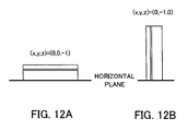
- correction is performed such that any two directions of the x-axis direction, the y-axis direction and the z-axis direction are at the 0g level.
- the body is placed so as to be oriented in one direction, and calibration is performed for a first axial direction (x-axis direction in FIG. 12(A) ) and a second axial direction (y-axis direction in FIG. 12(A) ); and thereafter, the body is placed so as to be oriented in another direction, and calibration is performed for the first axial direction (x-axis direction in FIG. 12(A) ) and a third axial direction (z-axis direction in FIG. 12(A) ), thereby correcting deviation of the reference directions in all three axes.
- Patent Document 1 Japanese Unexamined Patent Application Publication No. 2004-93552
- calibration is performed by placing a circuit board, to which a three-axis acceleration sensor is mounted, or an electronic device including the circuit board on a horizontal plane; however, this horizontal plane needs to be a plane that is exactly horizontal relative to gravity. The reason is that it is difficult to perform accurate calibration if the horizontal plane is inclined relative to gravity. Therefore, when calibration is performed, a tool and jig that can secure an accurate horizontal plane relative to gravity are required separately.
- the present invention has been made in view of the aforementioned problems, and an object thereof is to provide a electronic device with a built-in inclination sensor and a correction method, with which a user oneself can easily perform accurate calibration.
- the small-sized electronic device with a built-in inclination sensor is characterized by including: an inclination sensor that calculates inclination; a control unit that performs predetermined control based on a value calculated by the inclination sensor; a case that includes the inclination sensor and the control unit inside thereof; and a suspension portion that suspends the case, in which the control unit performs correction control of a reference value of the inclination sensor, based on a state in which the case is suspended by way of the suspension portion and has come to rest.
- the control unit performs correction control of a reference value of the inclination sensor, based on an inclination angle of the case relative to a vertical direction in a state of being suspended and having come to rest.
- the small-sized electronic device with a built-in inclination sensor further includes an operation unit; and a display unit that displays predetermined information, and when an operation to perform correction control of a reference value of the inclination sensor is performed via the operation unit, the control unit performs control such that the display unit displays information that prompts to suspend the case by way of the suspension portion.
- the control unit performs the correction control after a predetermined period of time has elapsed since the operation.
- the control unit determines whether an inclination angle related to a value calculated by the inclination sensor coincides with a predetermined inclination angle, and in a case of having determined not to coincide, calculates an amount of deviation from the predetermined inclination angle, and performs the correction control based the amount of deviation.
- the small-sized electronic device with a built-in inclination sensor further includes an operation unit; and a display unit that displays information, and when an operation to perform correction control of a reference value of the inclination sensor is performed via the operation unit, the control unit performs a predetermined calculation regarding the correction control, performs control such that the display unit displays a screen for confirming whether to perform the correction control based on a result of the calculation, and accepts a confirmation operation via the operation unit, and determines whether to perform the correction control based on the result of the calculation depending on a result thus accepted.
- control unit calculates an amount of deviation from the predetermined inclination angle, calculates an average value of the amount of deviation and a plurality of amounts of deviation calculated previously, and performs the correction control based on the average value.
- the case includes a first case and a second case that are connected so as to be openable and closable via a connecting portion, and the control unit performs the correction control taking into account whether the case is in an opened state or a closed state.
- the case includes a first case and a second case that are connected so as to be openable and closable via a connecting portion, and when an operation to command execution of correction control of a reference value of the inclination sensor is performed via the operation unit, the control unit performs control such that the display unit displays information that prompts to suspend the case in any one of an opened state or a closed state.
- a strap is attached as a suspension member to the suspension portion.
- the case further includes a memory card mounting portion to which a memory card is removably mounted, and the control unit performs the correction control taking into account of the existence of a memory card mounted to the memory card mounting portion.
- the inclination sensor is configured so as to calculate inclination by detecting acceleration, and the control unit monitors acceleration detected by the inclination sensor and an inclination angle that is calculated, and performs the correction control in a case of having determined that the acceleration detected by the inclination sensor is in a state that does not fluctuate, and that the inclination angle that is calculated falls within a predetermined angle range with a vertical direction as a reference.
- the inclination sensor is configured so as to calculate inclination by detecting acceleration, and that the control unit performs the correction control or processing related to the correction control in a state in which acceleration detected by the inclination sensor does not fluctuate.
- the small-sized electronic device with a built-in inclination sensor is characterized by including: an inclination sensor that calculates inclination; a case that incorporates the inclination sensor; and a communication cable part that outputs a signal related to a value calculated by the inclination sensor to an external device, in which correction control of a reference value is performed in the inclination sensor, based on a state in which the case is suspended by way of the communication cable part and has come to rest.
- a correction method is a method of correcting a reference value of an inclination sensor in a small-sized electronic device with a built-in inclination sensor, including the inclination sensor and a case accommodating the inclination sensor inside thereof, and the method is characterized by including: an inclination detecting step of detecting inclination by way of the inclination sensor; and a correcting step of performing correction control of a reference value of the inclination sensor, based on a state in which the case is suspended by way of the suspension portion and has come to rest.
- the user oneself can easily perform accurate calibration.
- FIG. 1 is a perspective view showing an appearance of a cellular telephone device 1 as an example of a small-sized electronic device with a built-in inclination sensor according to the present invention. It should be noted that, although FIG. 1 shows a so-called flip-type cellular telephone device, the small-sized electronic device with a built-in inclination sensor according to the present invention is not limited thereto.
- it may be a slider type in which one of the bodies slides to one direction in a state in which the bodies are mutually superimposed; a rotating (turning) type in which one of the bodies is rotated around an axis line along the direction of superimposition; and a type (straight type) in which an operation unit and a display unit are disposed in one case without having a connecting portion.
- the cellular telephone device 1 is configured to include an operation unit side case 2 and a display unit side case 3.
- the operation unit side case 2 is configured to include, on a front face portion 10 thereof, an operation unit 11 and a microphone 12 to which sound, which a user of the cellular telephone device 1 produces during a phone call, is input.
- the operation unit 11 is configured with: feature setting operation buttons 13 for operating various settings and various features such as a telephone number directory feature and a mail feature; input operation buttons 14 for inputting digits of a telephone number and characters for mail, and a selection operation button 15 that performs selection of the various operations and scrolling.
- the display unit side case 3 is configured to include, on a front face portion 20, an LCD (Liquid Crystal Display) display unit 21 for displaying a variety of information, and a speaker 22 for outputting sound of the other party of the conversation.
- LCD Liquid Crystal Display
- an upper end portion of the operation unit side case 2 and a lower end portion of the display unit side case 3 are connected via a hinge mechanism 4. Furthermore, by relatively pivoting the operation unit side case 2 and the display unit side case 3, connected via the hinge mechanism 4, the cellular telephone device 1 can be in a state where the operation unit side case 2 and the display unit side case 3 are apart from each other (opened state), and in a state where the operation unit side case 2 and the display unit side case 3 are folded (folded state).
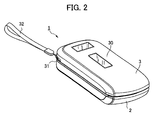
- FIG. 2 is a perspective view showing a state in which the cellular telephone device 1 is folded.
- the operation unit side case 2 includes, on its outer planar portion, a sub LCD display unit 30 that displays a clock, incoming notice of mail, etc.
- an attachment portion 31 (suspension portion), to which a suspension member 32 (a hand strap or a neck strap shaped like a cord) is attached when suspending the case, is formed at a corner of the display unit side case 3.
- the attachment portion 31 is formed at the corner of the display unit side case 3 in the present embodiment, it may be formed anywhere without being limited to a corner, and may be formed on the operation unit side case 2.
- an LCD is shown as an example of the display unit in the foregoing, naturally the display unit may be configured by a device other than an LCD, such as an OLED (organic light-emitting diode).
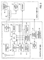
- FIG. 3 is a functional block diagram showing functions of the cellular telephone device 1.
- the operation unit side case 2 includes an operation unit 11, a microphone 12, a main antenna 40, an RF circuit unit 41, an LCD control unit 42, a sound processing unit 43, memory 44, an acceleration sensor 45 (inclination sensor), a light emitting unit 46, a power supply control circuit unit 47, an opened-closed detection sensor 48, a CPU 49 (control unit), and a rechargeable battery 50; and the display unit side case 3 includes an LCD display unit 21, a speaker 22, a driver IC 23, and a sub LCD display unit 30.
- the main antenna 40 communicates with external devices by way of a predetermined usable frequency band (for example, 800 MHz). It should be noted that, although the predetermined usable frequency band is set to 800 MHz in the present embodiment, other frequency bands may also be used.
- the main antenna 40 can be configured as a so-called dual band compatible antenna that can be compatible with another usable frequency band (for example, 2 GHz) in addition to the predetermined usable frequency band.
- the RF circuit unit 41 performs demodulation processing on a signal received via the main antenna 40, transmits the processed signal to the CPU 49, performs modulation processing on a signal received from the CPU 49, and transmits the processed signal to an external device (base station) via the main antenna 40. Furthermore, intensity of a signal received via the main antenna 40 is meanwhile notified to the CPU 49.
- the LCD control unit 42 performs predetermined image processing in accordance with control by the CPU 49, and outputs the processed image data to the driver IC 23.
- the driver IC 23 stores the image data, which is transmitted from the LCD control unit 42, in frame memory so as to be output to the LCD display unit 21 or the sub LCD display unit 30 at predetermined timing.
- the sound processing unit 43 performs predetermined sound processing in accordance with control by the CPU 49 for a signal transmitted from the RF circuit unit 41, and outputs the processed signal to the speaker 22.
- the speaker 22 externally outputs the signal that is transmitted from the sound processing unit 43.
- the sound processing unit 43 processes a signal, which is input from the microphone 12, in accordance with control by the CPU 49, and outputs the processed signal to the RF circuit unit 41.
- the RF circuit unit 41 performs predetermined processing on the signal transmitted from the sound processing unit 43, and outputs the processed signal to the main antenna 40.
- the memory 44 includes, for example, working memory, and is utilized for arithmetic processing by the CPU 49. It should be noted that the memory 44 may also serve as detachable external memory.
- the acceleration sensor 45 detects acceleration applied to the cellular telephone device 1, and outputs a detection result to the CPU 49.
- the acceleration sensor 45 obtains acceleration for each axis, for example, by measuring a force applied to the cellular telephone device 1 by way of a piezoelectric element, and converts the acceleration into numeric data to be buffered.
- the CPU 49 then reads acceleration data that has been periodically buffered.
- the acceleration sensor 45 is not limited to the piezoelectric element (piezoelectric type), and it may be configured as an MEMS (Micro Electro Mechanical Systems) type utilizing a piezoresistance type, an electrostatic capacitance type, a heat detecting type, or the like, a servo type that moves a movable coil that is returned by a feedback electric current, a strain gauge type that measures strain occurring due to acceleration by way of a strain gauge, etc.
- MEMS Micro Electro Mechanical Systems
- the light emitting unit 46 is configured so as to emit light based on a voltage supplied from the power supply control circuit unit 47, and is configured with, for example, an LED (light emitting diode). It should be noted that, although only a single light emitting unit 46 is shown in FIG. 3 for simplicity, a plurality of different light emitting units are actually provided in predetermined locations of the case.
- the calibration may be executed with a predetermined operation having been performed by a user as a trigger (manual calibration), and may be executed with the case having settled within a predetermined angle range and having come to rest as a trigger (automatic calibration).
- the CPU 49 When the suspension member 32 is attached to the attachment portion 31, and the case (cellular telephone device 1) is suspended, the CPU 49 performs correction control of a reference value of the acceleration sensor 45, based on the state of being suspended and having come to rest. It should be noted that the CPU 49 is monitoring fluctuation of a detection value of the acceleration sensor 45, and when detecting only 1g in a constant direction, and detecting a state in which fluctuation of acceleration to other directions is not occurring, the CPU 49 determines that the case is in a resting state (to be described later in detail).
- the CPU 49 performs correction control of a reference value of the acceleration sensor 45, based on a difference of an inclination angle of the case in the state of being suspended and having come to rest and an angle of a vertical direction.
- the cellular telephone device 1 includes the operation unit 11 (operation unit) that performs an operation to command execution of correction control of a reference value of the acceleration sensor 45, and the LCD display unit 21 (display unit) that displays predetermined information.
- the CPU 49 controls the LCD display unit 21 to display information that prompts to attach the suspension member 32 to the attachment portion 31 so as to suspend the case.
- the CPU 49 controls the LCD display unit 21 to display in a case in which the case is in the opened state, and controls the sub LCD display unit 30 to display in a case in which the case is in the closed state.
- the explanation of the operating procedure regarding calibration is not limited to the display behavior of the LCD display unit 21, and may be performed by way of a voice output behavior of the speaker 22.
- the CPU 49 performs correction control after a predetermined period of time has elapsed from the operation.
- calibration in the manual calibration, since calibration is not performed until a predetermined period of time (for example, several seconds) has elapsed after a predetermined operation by the user was performed, calibration is performed after the suspension member 32 has been attached to the attachment portion 31 and the case has been suspended and has come to rest; therefore, calibration can be performed by excluding a state of being held by the user and a state of jiggling immediately after being suspended.
- a predetermined period of time for example, several seconds
- the CPU 49 determines whether an inclination angle according to a value calculated by the acceleration sensor 45 coincides with a predetermined inclination angle (reference value), and in a case in which the CPU 49 has determined that it does not coincide therewith, it is preferable that the CPU 49 calculates an amount of deviation from the predetermined inclination angle, and performs correction control based on the amount of deviation.
- the CPU 49 performs predetermined calculation regarding the correction control, performs control, based on a result of the calculation, such that a confirmation operation screen to confirm whether correction control is performed is displayed on the LCD display unit 21, accepts an operation on the confirmation operation screen via the operation unit 11, and determines whether correction control is performed, based on a result of the calculation depending on a result thus accepted.
- the user in a state in which the suspension member 32 is attached to the attachment portion 31, and the case is suspended, the user can select whether calibration of the acceleration sensor 45 is performed with the present invention.
- the CPU 49 determines whether an inclination angle according to a value calculated by the acceleration sensor 45 coincides with a predetermined inclination angle (reference value), and in a case of having determined that it does not coincide therewith, it is preferable that the CPU 49 calculates an amount of deviation from the predetermined inclination angle, calculates an average value of the amount of deviation and a plurality of amounts of deviation calculated in the past, and performs correction control based on the average value.
- the acceleration sensor 45 detects inclination of the cellular telephone device 1
- an animated image displayed on the LCD display unit 21 changes in accordance with a value of such detection
- a sense of discomfort is given to the user unless the 0g level of the acceleration sensor 45 is set to a level where the user usually operates.
- the user will feel discomfort.
- the place for performing calibration is different from the place where the user usually performs calibration
- the 0g level after the calibration will be different from the usual 0g level, due to the bias unique to the place. Since the user performs an operation of an inclination angle based on the 0g level of the acceleration sensor 45 after the calibration that is performed at the usual place, if the 0g level of the acceleration sensor 45 is different from the usual level, the user will feel discomfort in the operating feeling. On the other hand, in other applications, it may be required to calculate an accurate inclination angle by way of the acceleration sensor 45 in some cases.
- the cellular telephone device 1 Accordingly, in the cellular telephone device 1 according to the present invention, calibration is performed based on an average value of amounts of deviation calculated in the past; therefore, a sense of discomfort is not given to the user in the operation feeling of an inclination angle, and calculation of an accurate inclination angle can also be performed.
- the CPU 49 performs correction control by considering the difference between the opened state and the closed state. If the weight balance is different between a case in which the cellular telephone device 1 is suspended by way of the suspension member 32 in the opened state, and a case in which the cellular telephone device 1 is suspended by way of the suspension member 32 in the closed state, it is necessary to change the calibration data depending on the state. Since the present invention can accommodate for the opened state and the closed state, accurate calibration can be performed regardless of the state of the cellular telephone device 1. It should be noted that, although it has been assumed in the present embodiment that the cellular telephone device 1 assumes the two states of the opened state and the closed state, it is not limited thereto, and a configuration may be employed so as to perform calibration by considering differences of various states.
- the cellular telephone device 1 includes a memory card slot 51, and the weight balance changes by mounting a memory card in the slot.
- the CPU 49 may be configured so as to determine whether the memory card is mounted to the memory card slot 51, and the calculation of calibration changes between a suspended state when the memory card is mounted and a suspended state when the memory card is not mounted.
- the CPU 49 performs control such that the LCD display unit 21 displays information that prompts to suspend the case in any one of the opened state or the closed state (or any one of the state where the memory card is mounted or the state where the memory card is not mounted).
- the state of the cellular telephone device 1 when performing calibration is instructed to the user utilizing the LCD display unit 21, it is not necessary to assume a plurality of states of the cellular telephone device 1 when performing calibration, and thus the processing load can be reduced.
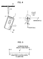
- the user keeps it suspended from the pole 60 or the like by way of the suspension member 32. Subsequently, for example, in the automatic calibration, in a case in which the state of being suspended has continued for a predetermined period of time, calibration of three axial directions (x, y, z) including the gravity direction is performed. According to this method, deviation of the 0g level due to temperature change or the like can be automatically corrected, and accurate acceleration data can always be obtained.
- FIG. 4 shows acceleration applied in each direction when the cellular telephone device 1 is suspended from the pole 60 or the like by way of the suspension member 32. It should be noted that, for the convenience of explanation, it is assumed in the following that a component in the z-axis direction is at a 0g level in a state where the case is suspended by way of the suspension member 32 and has come to rest (naturally, there is also a case in which the component in the z-axis direction is not at the 0g level depending on the position of attaching the suspension member 32).
- acceleration applied in the x-axis direction, the y-axis direction, and the x-axis direction is different depending on the position attaching the suspension member 32 of the cellular telephone device 1, the fact that the 1g level appears only in the vertical direction in the resting state does not change.
- the CPU 49 is monitoring acceleration for each axis of the acceleration sensor 45 and an inclination angle that is calculated. In addition, the CPU 49 determines whether the acceleration detected by the acceleration sensor 45 has entered a state that does not fluctuate, and the inclination angle that is calculated has entered a state of falling within a predetermined angle range. In a case in which it has been determined that they have entered such states, calibration is automatically performed in the automatic calibration.
- the predetermined angle range is a range of values with some allowance for a value detected when the case is suspended in a state where the detection value of the acceleration sensor 45 is accurate.
- a state in which an inclination angle within this angle range is detected, and in which the acceleration does not fluctuate can be identified as a state in which the case is suspended and has come to rest, even in a state in which minute deviation is occurring to a degree that the acceleration sensor 45 requires calibration.
- the CPU 49 has determined this state, calibration is automatically performed in the automatic calibration.
- the cellular telephone device 1 In the usage state of the cellular telephone device 1, the cellular telephone device 1 is unlikely to be placed on a table at the same inclination angle as when the suspension member 32 is suspended from the pole 60 or the like; therefore, in the automatic calibration, calibration will not be performed in a state that is different from a state assumed in advance (a state of being suspended from the pole 60 or the like via the suspension member 32).
- the inclination angle may approximate an inclination angle when being suspended from the pole 60 or the like via the suspension member 32, and the acceleration data may approximate the expected value.
- the situation can be distinguished since fluctuation of acceleration in each axis continues to occur due to minute vibrations of the arm, and thus the situation is different from a situation of being suspended from the pole 60 or the like via the suspension member 32 and fixed.
- the acceleration sensor 45 detects acceleration data, and calibration processing of the 0g level of the acceleration sensor 45 is executed.
- the absolute value of the acceleration in the vertical direction being "1" is assumed as the condition for performing calibration; however, strictly speaking, in the situation of being suspended from the pole 60 or the like via the suspension member 32, due to the performance of the acceleration sensor 45, a state of an accurate value "1" as acceleration data is not assumed, and minute changes will be repeated around the value "1".
- the user in a case in which the automatic calibration has been performed, the user is notified by way of sound, light, display, etc. of the fact that the calibration has been automatically performed, and in response to this notification, the user can determine whether the calibration should be adopted. In a case in which the calibration is not adopted, the user can cancel the calibration by performing a predetermined operation.
- the user can use the cellular telephone device 1 with the 0g level.
- the user can determine whether a result of calibration by the automatic calibration should be employed with the present invention; therefore, in a case in which the automatic calibration is automatically performed when the user intentionally suspends the cellular telephone device 1 from the pole 60 or the like via the suspension member 32, or in a case in which the automatic calibration is automatically performed when a predetermined period of time has elapsed after the user intentionally suspended the cellular telephone device 1 from the pole 60 or the like via the suspension member 32, calibration can be prevented from being performed without being noticed by the user.
- FIG. 5 a calibration condition is described using FIG. 5 .
- the 0g level after calibration is different between a case in which calibration is performed near "A" (+ direction) and a case in which calibration is performed near "B" (- direction); therefore, there is a possibility that the 0g level serving as a reference may vary depending on the place or the like of performing calibration.
- an average value of acceleration data is obtained each time calibration is performed, and calibration is performed based on this average value.
- the present invention by averaging the acceleration data, even if the place of performing calibration is a place that is different from usual, and the 0g level is different from the value of calibration that is usually performed, it is possible to perform averaging with the acceleration data used (accumulated) for calibrations up to now; therefore, deviation of the reference value is reduced, and calibration can be performed with an accurate 0g level that is not extremely biased.
- Step S1 a method of performing calibration is described with reference to the flowchart shown in FIG. 6 .
- the suspension member 32 is referred to as a strap in the following.
- expected values are set in advance (Step S1).
- setting of expected values is described. Acceleration in the x-axis direction (x_acc), acceleration in the y-axis direction (y_acc) and acceleration in the z-axis direction (z_acc) in a case in which the cellular telephone device 1 is suspended from the pole 60 or the like via a strap are measured in advance, and values thus measured are stored in the memory 44, etc. as expected values of the calibration condition.
- Step S1 expected values in a state in which the strap of the cellular telephone device 1 in the opened state is suspended from the pole 60 or the like, or expected values in a state in which the strap of the cellular telephone device 1 in the closed state is suspended from the pole 60 or the like may be stored in the memory 44.
- Step S2 the CPU 49 repeats each of Steps S3 to S6 until the timeout condition regarding the following Steps S3 to S6 is satisfied.
- the CPU 49 detects an inclination angle of the cellular telephone device 1 (Step S3).
- the CPU 49 calculates acceleration in the x-axis direction (x_acc_1), acceleration in the y-axis direction (y_acc_1) and acceleration in the z-axis direction (z_acc)_1, based on data provided from the acceleration sensor 45. It should be noted that, in the following, the acceleration in the x-axis direction (x_acc_1), the acceleration in the y-axis direction (y_acc_1) and the acceleration in the z-axis direction (z_acc)_1 are referred to as actual measurement values.
- the CPU 49 compares the expected value stored in advance in Step S1 and the actual measurement values calculated in Step S3 for the respective axes (Step S4).
- the CPU 49 determines whether a certain calibration condition is satisfied, based on a comparison result in Step S4 (Step S5).
- the case in which a certain calibration condition is satisfied refers to a case in which the expected values and the actual measurement values coincide with each other in all the axes, or fall within a certain range.
- the processing advances to Step S6, and in a case in which the certain calibration condition is not satisfied (No), the processing advances to Step S7.
- Step S6 the CPU 49 then confirms whether the determination has been obtained for an arbitrary number of times.
- the CPU 49 is periodically monitoring detection values of the acceleration sensor 45, and determines whether such periodical detection results continuously satisfy the condition.
- this step is performed in order to confirm that the cellular telephone device 1 is actually suspended from the pole 60 or the like via the strap. It should be noted that this step is not essential, and may be skipped.
- Step S5 or S6 the CPU 49 determines whether a time t has been reached.
- the time t can be arbitrarily set, and is set as a time that is sufficient for allowing determination that the cellular telephone device 1 is suspended via the strap, and a time that is sufficiently longer than a plurality of cycle times of obtaining data of the acceleration sensor 45 (for example, 1 second).
- the processing is terminated, and in a case in which the time t has not been reached, the processing is continued.
- the time t has been reached to terminate the processing (timeout)
- the user may be notified of the fact that the calibration processing has not been performed via sound, light, display, etc.
- Step S5 the CPU 49 performs calibration.
- calibration accuracy may be enhanced by averaging the 0g level for each calibration processing.
- confirmation with the user may be made as to whether the previous state is acceptable, via sound, light, display, etc.
- processing has been described above as being performed simultaneously in the x-axis direction, the y-axis direction and the z-axis direction, it is not limited thereto, and a configuration may be employed in which processing is separately performed in each axis direction, and in a case in which it has been determined that any one axis direction does not satisfy a certain calibration condition in Step S5, calibration is not performed.
- a small-sized electronic device such as a portable gaming machine, a portable navigation device and a PDA may be applicable as long as an inclination sensor is built therein and a holding angle is required to be detected.
- application to a digital camera may include a case in which an inclination sensor is built therein for camera shake correction when taking pictures or for assisting in photographing, etc., calibration of such an inclination sensor can be easily and accurately performed by applying the present invention thereto.
- the present invention is not limited to the small-sized electronic device that can operate alone as described above, and the effects according to the present invention can be achieved also when applied to a small-sized electronic device (for example, a controller of a gaming machine) incorporating the acceleration sensor 45 and being used by being connected to an external device that does not have portability.
- a small-sized electronic device for example, a controller of a gaming machine
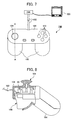
- a controller 100 includes: the acceleration sensor 45 (inclination sensor) that calculates inclination based on detected acceleration; a case 101 that incorporates the acceleration sensor 45; and a communication cable part 102 that outputs a signal according to a calculation value in the acceleration sensor 45 to outside of the housing.
- the acceleration sensor 45 when the case 101 is suspended via the communication cable part 102, correction control of a reference value is performed based on a state of being suspended and having come to rest. It should be noted that the configuration and behavior of the acceleration sensor 45 are similar to those described above.
- FIG. 7 shows a top plan view of the controller 100
- FIG. 8 shows a cross-sectional view when sectioned along a line A-A of FIG. 7
- FIG. 9 shows a state in which the case 101 is suspended via the communication cable part 102 when calibrating the acceleration sensor 45.
- the controller 100 includes: push switches 103 that perform a depression operation; a direction operation key 104 that performs a direction operation; grips 105; and levers 106. It should be noted that the configuration of the controller 100 is an example, and is not limited to the present embodiment.
- calibration of the 0g level of the acceleration sensor 45 is performed in a processing unit (not shown) of a main case 200 that is electrically connected to the controller 100 via the communication cable part 102. It should be noted that the calibration procedure to be performed by way of the processing unit of the main case 200 is similar to those performed by way of the CPU 49 as described above.
- the main case 200 is connected to a monitor 300 that displays an image processed by a microcomputer in the main case.
- a monitor 300 that displays an image processed by a microcomputer in the main case.
- the display supporting calibration on the LCD display unit 21 as described above is similarly displayed on the monitor 300.
- an accurate direction relative to gravity can be easily established when performing calibration of the acceleration sensor 45; therefore, for example, in a case in which deviation occurs in the 0g level of the acceleration sensor 45 while the user is using the controller 100, by selecting the manual calibration, accurate calibration can be performed by the user oneself as many times as desired, and accurate acceleration data can always be obtained.
Claims (15)
- Dispositif électronique compact (1, 100), tel qu'un téléphone cellulaire, une machine de jeux portable, un dispositif de navigation portable, un assistant numérique personnel ou une caméra numérique, avec un capteur d'inclinaison intégré (45), comprenant :un capteur d'inclinaison (45) qui calcule une valeur de calcul qui est relative à un angle d'inclinaison ;une unité de commande (49) qui exécute une commande prédéterminée sur la base de la valeur de calcul calculée par le capteur d'inclinaison (45) ;un boîtier (101) qui comprend à l'intérieur le capteur d'inclinaison (45) et l'unité de commande (49) ; caractérisé parune partie de suspension (31) qui suspend le boîtier (101),dans lequel l'unité de commande (49) exécute une commande de correction d'une valeur de référence du capteur d'inclinaison (45), sur la base d'un état dans lequel le boîtier (101) est suspendu au moyen de la partie de suspension (31) et s'est immobilisé.
- Dispositif électronique compact (1, 100) avec un capteur d'inclinaison intégré selon la revendication 1, dans lequel, quand le boîtier (101) est suspendu au moyen de la partie de suspension (31), l'unité de commande (49) exécute une commande de correction de la valeur de référence du capteur d'inclinaison (45), sur la base d'un angle d'inclinaison du boîtier (101) par rapport à une direction verticale dans un état où il est suspendu et s'est immobilisé.
- Dispositif électronique compact (1, 101) avec un capteur d'inclinaison intégré selon la revendication 1, comprenant en outre :une unité d'opérations (11) ; etune unité d'affichage (21) qui affiche des informations prédéterminées,dans lequel, quand une opération pour exécuter une commande de correction d'une valeur de référence du capteur d'inclinaison (45) est effectuée via l'unité d'opérations (11), l'unité de commande (49) exécute une commande telle que l'unité d'affichage (21) affiche des informations qui invitent à suspendre le boîtier au moyen de la partie de suspension (31).
- Dispositif électronique compact (1, 100) avec un capteur d'inclinaison intégré selon la revendication 3, dans lequel, quand une opération pour exécuter la commande de correction est effectuée via l'unité d'opérations (11), l'unité de commande (49) exécute la commande de correction après qu'une période de temps prédéterminée s'est écoulée depuis l'opération.
- Dispositif électronique compact (1, 100) avec un capteur d'inclinaison intégré selon la revendication 1, dans lequel, quand le boîtier (101) est suspendu au moyen de la partie de suspension (31), l'unité de commande (49) détermine si un angle d'inclinaison relatif à la valeur de calcul calculée par le capteur d'inclinaison (45) coïncide avec un angle d'inclinaison prédéterminé et, dans un cas où elle aurait déterminé qu'il ne coïncide pas, calcule une quantité d'écart par rapport à l'angle d'inclinaison prédéterminé, et exécute la commande de correction sur la base de la quantité d'écart.
- Dispositif électronique compact (1, 100) avec un capteur d'inclinaison intégré selon la revendication 5, comprenant en outre :une unité d'opérations (11) ; etune unité d'affichage (21) qui affiche des informations,dans lequel, quand une opération pour exécuter une commande de correction d'une valeur de référence du capteur d'inclinaison est effectuée via l'unité d'opérations (11), l'unité de commande (49) effectue un calcul prédéterminé concernant la commande de correction, exécute une commande telle que l'unité d'affichage affiche (21) un écran pour confirmer l'exécution ou non de la commande de correction sur la base d'un résultat du calcul, et accepte une opération de confirmation via l'unité d'opérations (11), et détermine d'exécuter ou non la commande de correction sur la base du résultat du calcul en fonction d'un résultat ainsi accepté.
- Dispositif électronique compact (1, 100) avec un capteur d'inclinaison intégré selon la revendication 5, dans lequel, dans le cas où elle aurait déterminé qu'il ne coïncide pas, l'unité de commande (49) calcule une quantité d'écart par rapport à l'angle d'inclinaison prédéterminé, calcule une valeur moyenne de la quantité d'écart et d'une pluralité de quantités d'écart calculées précédemment, et exécute la commande de correction sur la base de la valeur moyenne.
- Dispositif électronique compact (1, 100) avec un capteur d'inclinaison intégré selon la revendication 1,
dans lequel le boîtier (101) comprend un premier boîtier et un deuxième boîtier qui sont connectés de manière à pouvoir être ouverts et fermés via une portion de connexion, et
dans lequel l'unité de commande exécute la commande de correction en tenant compte du fait que le boîtier est dans un état ouvert ou un état fermé. - Dispositif électronique compact avec un capteur d'inclinaison intégré selon la revendication 3,
dans lequel le boîtier comprend un premier boîtier (2) et un deuxième boîtier (3) qui sont connectés de manière à pouvoir être ouverts et fermés via une portion de connexion (4), et
dans lequel, quand une opération pour commander l'exécution de commande de correction d'une valeur de référence du capteur d'inclinaison (45) est effectuée via l'unité d'opérations (11), l'unité de commande (49) exécute une commande telle que l'unité d'affichage (21) affiche des informations qui invitent à suspendre le boîtier (101) dans l'un quelconque d'un état ouvert ou d'un état fermé. - Dispositif électronique compact (1, 100) avec un capteur d'inclinaison intégré selon la revendication 1, dans lequel une sangle est fixée comme un élément de suspension (33) à la partie de suspension (31).
- Dispositif électronique compact (1, 100) avec un capteur d'inclinaison intégré selon la revendication 1,
dans lequel le boîtier (101) comprend en outre une partie de montage de carte de mémoire (51) sur laquelle une carte de mémoire peut être montée de manière amovible, et
dans lequel l'unité de commande (49) exécute la commande de correction en tenant compte de l'existence d'une carte de mémoire montée sur la partie de montage de carte de mémoire (51). - Dispositif électronique compact (1, 100) avec un capteur d'inclinaison intégré selon la revendication 1,
dans lequel le capteur d'inclinaison (45) est configuré de manière à calculer une inclinaison en détectant une accélération, et
dans lequel l'unité de commande (49) surveille une accélération détectée par le capteur d'inclinaison (45) et un angle d'inclinaison qui est calculé, et exécute la commande de correction dans un cas où elle aurait déterminé que l'accélération détectée par le capteur d'inclinaison (45) est dans un état qui ne fluctue pas, et que l'angle d'inclinaison qui est calculé rentre dans une plage d'angles prédéterminée avec une direction verticale comme référence. - Dispositif électronique compact (1, 100) avec un capteur d'inclinaison intégré selon la revendication 1,
dans lequel le capteur d'inclinaison (45) est configuré de manière à calculer une inclinaison en détectant une accélération, et
dans lequel l'unité de commande (49) exécute la commande de correction ou le traitement relatif à la commande de correction dans un état dans lequel l'accélération détectée par le capteur d'inclinaison (45) ne fluctue pas. - Dispositif électronique compact (100), tel qu'un téléphone cellulaire, une machine de jeux portable, un dispositif de navigation portable, un assistant numérique personnel ou une caméra numérique, avec un capteur d'inclinaison intégré (45), comprenant :un capteur d'inclinaison qui calcule une valeur de calcul qui est relative à un angle d'inclinaison ;un boîtier (101) qui comprend à l'intérieur le capteur d'inclinaison (45) ; etune partie de câble de communication (102) qui délivre en sortie un signal relatif à la valeur de calcul calculée par le capteur d'inclinaison (45) à un dispositif externe (200), caractérisé en ce queune commande de correction d'une valeur de référence est effectuée dans le capteur d'inclinaison (45), sur la base d'un état dans lequel le boîtier (101) est suspendu au moyen de la partie de câble de communication (102) et s'est immobilisé.
- Procédé de correction d'une valeur de référence d'un capteur d'inclinaison dans un dispositif électronique compact (1, 100), tel qu'un téléphone cellulaire, une machine de jeux portable, un dispositif de navigation portable, un assistant numérique personnel ou une caméra numérique, avec un capteur d'inclinaison intégré, comprenant le capteur d'inclinaison (45) et un boîtier (101) logeant à l'intérieur le capteur d'inclinaison (45) ; le procédé comprenant :- une étape de détection d'inclinaison pour détecter une inclinaison au moyen du capteur d'inclinaison (45) ; caractérisé parune étape de correction pour exécuter une commande de correction d'une valeur de référence du capteur d'inclinaison, sur la base d'un état dans lequel le boîtier (101) est suspendu au moyen de la partie de suspension (32) et s'est immobilisé.
Applications Claiming Priority (2)
| Application Number | Priority Date | Filing Date | Title |
|---|---|---|---|
| JP2008047327A JP4861357B2 (ja) | 2008-02-28 | 2008-02-28 | 傾斜センサ内蔵小型電子機器及び補正方法 |
| PCT/JP2009/053671 WO2009107774A1 (fr) | 2008-02-28 | 2009-02-27 | Dispositif électronique compact avec capteur d'inclinaison intégré et procédé de correction |
Publications (3)
| Publication Number | Publication Date |
|---|---|
| EP2249124A1 EP2249124A1 (fr) | 2010-11-10 |
| EP2249124A4 EP2249124A4 (fr) | 2011-05-04 |
| EP2249124B1 true EP2249124B1 (fr) | 2012-08-29 |
Family
ID=41016159
Family Applications (1)
| Application Number | Title | Priority Date | Filing Date |
|---|---|---|---|
| EP09715955A Not-in-force EP2249124B1 (fr) | 2008-02-28 | 2009-02-27 | Dispositif electronique compact avec capteur d'inclinaison integre et procede de correction |
Country Status (6)
| Country | Link |
|---|---|
| US (1) | US9008987B2 (fr) |
| EP (1) | EP2249124B1 (fr) |
| JP (1) | JP4861357B2 (fr) |
| KR (1) | KR101231440B1 (fr) |
| CN (1) | CN101960255B (fr) |
| WO (1) | WO2009107774A1 (fr) |
Families Citing this family (18)
| Publication number | Priority date | Publication date | Assignee | Title |
|---|---|---|---|---|
| JP2011078002A (ja) * | 2009-10-01 | 2011-04-14 | Nikon Corp | 撮像装置 |
| US8880373B2 (en) * | 2009-11-04 | 2014-11-04 | Qualcomm Incorporated | Accurate magnetic compass in mobile electronic device |
| JP5558956B2 (ja) * | 2010-07-29 | 2014-07-23 | キヤノン株式会社 | 撮像装置およびその制御方法 |
| JP5443332B2 (ja) * | 2010-12-27 | 2014-03-19 | リンナイ株式会社 | ガス炊飯器 |
| JP5383756B2 (ja) * | 2011-08-17 | 2014-01-08 | ファナック株式会社 | 学習制御機能を備えたロボット |
| US8886359B2 (en) | 2011-05-17 | 2014-11-11 | Fanuc Corporation | Robot and spot welding robot with learning control function |
| US9541393B2 (en) | 2011-06-30 | 2017-01-10 | Qualcomm Incorporated | Reducing power consumption or error of digital compass |
| CN103424096A (zh) * | 2012-05-17 | 2013-12-04 | 西安闻泰电子科技有限公司 | 通过手机测量角度的方法 |
| CN103090882B (zh) * | 2013-01-07 | 2015-03-18 | 上海步略科技有限公司 | 加速度计实现倾角测量应用中的灵敏轴非正交补偿校正方法 |
| US9921648B2 (en) * | 2013-02-22 | 2018-03-20 | University Of Seoul Industry Cooperation Foundation | Apparatuses, methods and recording medium for control portable communication terminal and its smart watch |
| CN103399177A (zh) * | 2013-08-15 | 2013-11-20 | 上海步略科技有限公司 | 加速度传感器实现倾角测量应用中的灵敏轴参数多点方程式校正标定方法 |
| EP2930466B1 (fr) * | 2014-04-09 | 2018-07-18 | Safran Vectronix AG | Appareil d'observation mobile doté d'un compas magnétique numérique |
| US10512983B2 (en) * | 2015-06-15 | 2019-12-24 | University Of Kentucky Research Foundation | Method and apparatus for measurement of three-dimensional welding torch orientation for a welding process without using a magnetometer |
| JP6514089B2 (ja) * | 2015-11-02 | 2019-05-15 | 株式会社ソニー・インタラクティブエンタテインメント | 情報処理装置、情報処理システム、および情報処理方法 |
| CN106125160B (zh) * | 2016-06-14 | 2018-11-09 | 重庆蓝岸通讯技术有限公司 | 自动校准重力感应器方向的系统及方法 |
| CN110823201B (zh) * | 2019-11-18 | 2020-08-14 | 南京上美冠丰塑胶有限公司 | 喷涂挂架姿态激光检测仪 |
| CN111736181A (zh) * | 2020-05-08 | 2020-10-02 | 广州南方卫星导航仪器有限公司 | 高精度测绘型gnss接收机自检方法、电子设备、介质及系统 |
| CN111457893A (zh) * | 2020-05-11 | 2020-07-28 | 佛山市威格特电气设备有限公司 | 一种基于加速度传感器的杆塔倾角度检测方法 |
Family Cites Families (13)
| Publication number | Priority date | Publication date | Assignee | Title |
|---|---|---|---|---|
| JPS49107264A (fr) * | 1973-02-13 | 1974-10-11 | ||
| JP4354618B2 (ja) * | 2000-08-01 | 2009-10-28 | セイコーインスツル株式会社 | 電子方位計の調整方法、電子方位計調整システム、電子方位計および電子方位計付電子時計 |
| FR2836275B1 (fr) | 2002-02-18 | 2005-11-25 | Purple Labs | Dispositif muni d'un ecran rectangulaire |
| JP2004093552A (ja) | 2002-07-10 | 2004-03-25 | Hitachi Metals Ltd | 加速度検出装置 |
| US20060146009A1 (en) * | 2003-01-22 | 2006-07-06 | Hanno Syrbe | Image control |
| CN1774206A (zh) * | 2003-04-11 | 2006-05-17 | 松下电器产业株式会社 | 加速度传感器轴信息校正装置、及其校正方法 |
| JP2006139537A (ja) * | 2004-11-12 | 2006-06-01 | Sony Ericsson Mobilecommunications Japan Inc | 携帯端末及び携帯端末操作方法 |
| JP4552658B2 (ja) * | 2005-01-13 | 2010-09-29 | 日立金属株式会社 | 2軸磁気センサを用いた姿勢検知方法およびそのプログラム |
| JP4120648B2 (ja) * | 2005-02-23 | 2008-07-16 | ヤマハ株式会社 | 携帯端末、携帯端末の制御方法、プログラムおよび記録媒体 |
| EP1864082B1 (fr) * | 2005-03-18 | 2016-10-26 | Gatekeeper Systems, Inc. | Systeme de communication bidirectionnel permettant de suivre les positions et les etats de vehicules a roues |
| EP2821879A1 (fr) | 2006-01-06 | 2015-01-07 | Drnc Holdings, Inc. | Procédé d'entrer des commandes et/ou des caractères d'un dispositif portable de communication avec un capteur d'inclinaison |
| US8942764B2 (en) * | 2007-10-01 | 2015-01-27 | Apple Inc. | Personal media device controlled via user initiated movements utilizing movement based interfaces |
| GB2458297B (en) * | 2008-03-13 | 2012-12-12 | Performance Designed Products Ltd | Pointing device |
-
2008
- 2008-02-28 JP JP2008047327A patent/JP4861357B2/ja not_active Expired - Fee Related
-
2009
- 2009-02-27 EP EP09715955A patent/EP2249124B1/fr not_active Not-in-force
- 2009-02-27 US US12/920,051 patent/US9008987B2/en active Active
- 2009-02-27 KR KR1020107020022A patent/KR101231440B1/ko not_active IP Right Cessation
- 2009-02-27 WO PCT/JP2009/053671 patent/WO2009107774A1/fr active Application Filing
- 2009-02-27 CN CN2009801064281A patent/CN101960255B/zh not_active Expired - Fee Related
Also Published As
| Publication number | Publication date |
|---|---|
| KR20100111748A (ko) | 2010-10-15 |
| JP2009204467A (ja) | 2009-09-10 |
| CN101960255A (zh) | 2011-01-26 |
| US9008987B2 (en) | 2015-04-14 |
| JP4861357B2 (ja) | 2012-01-25 |
| CN101960255B (zh) | 2013-10-30 |
| EP2249124A4 (fr) | 2011-05-04 |
| KR101231440B1 (ko) | 2013-02-07 |
| US20110004439A1 (en) | 2011-01-06 |
| EP2249124A1 (fr) | 2010-11-10 |
| WO2009107774A1 (fr) | 2009-09-03 |
Similar Documents
| Publication | Publication Date | Title |
|---|---|---|
| EP2249124B1 (fr) | Dispositif electronique compact avec capteur d'inclinaison integre et procede de correction | |
| JP5838676B2 (ja) | 腕装着型の電子機器およびその制御方法 | |
| JP5701206B2 (ja) | 携帯機器の地磁気センサの補正方法、携帯機器及びプログラム | |
| WO2006008946A1 (fr) | Dispositif électronique | |
| KR20050059110A (ko) | 헤드 트랙킹 방법 및 장치 | |
| KR20100068334A (ko) | 입력 장치, 제어 장치, 제어 시스템 및 제어 방법 | |
| JP2009133695A (ja) | 電子機器 | |
| CN103017747A (zh) | 传感器元件及其制造方法、传感器装置以及电子设备 | |
| JP5264372B2 (ja) | 携帯電話端末及びアンテナ整合方法 | |
| WO2012039237A1 (fr) | Terminal mobile et procédé de contrôle d'affichage correspondant | |
| JP5543077B2 (ja) | 携帯電子機器 | |
| JP4805892B2 (ja) | 携帯電子機器 | |
| JP5289991B2 (ja) | 携帯電子機器 | |
| JP5297628B2 (ja) | 携帯電子機器及びその制御方法 | |
| JP5084556B2 (ja) | 携帯電子機器 | |
| JP5263956B2 (ja) | 電子機器及びプログラム | |
| JP2018169167A (ja) | 電子機器、電子時計、電子機器の制御方法及びプログラム | |
| JP2017026476A (ja) | 電子機器 | |
| JP4950156B2 (ja) | 携帯電子機器 | |
| JP4805891B2 (ja) | 携帯電子機器 | |
| KR100672576B1 (ko) | 이동통신 단말기의 진동모터 점검장치 | |
| JP5414303B2 (ja) | 携帯電子機器及びその制御方法 | |
| JP2005175813A (ja) | 電子機器、画像情報伝送システム及び方法 | |
| JP2006148687A (ja) | 携帯端末、および、その制御方法 | |
| JP2009260713A (ja) | 通信端末、通信方法、プログラム、および記録媒体 |
Legal Events
| Date | Code | Title | Description |
|---|---|---|---|
| PUAI | Public reference made under article 153(3) epc to a published international application that has entered the european phase |
Free format text: ORIGINAL CODE: 0009012 |
|
| 17P | Request for examination filed |
Effective date: 20100831 |
|
| AK | Designated contracting states |
Kind code of ref document: A1 Designated state(s): AT BE BG CH CY CZ DE DK EE ES FI FR GB GR HR HU IE IS IT LI LT LU LV MC MK MT NL NO PL PT RO SE SI SK TR |
|
| A4 | Supplementary search report drawn up and despatched |
Effective date: 20110405 |
|
| RIC1 | Information provided on ipc code assigned before grant |
Ipc: G01C 9/06 20060101ALI20110330BHEP Ipc: G01C 9/00 20060101AFI20090923BHEP Ipc: H04B 1/40 20060101ALI20110330BHEP Ipc: H04M 1/00 20060101ALI20110330BHEP Ipc: G01C 25/00 20060101ALI20110330BHEP |
|
| GRAP | Despatch of communication of intention to grant a patent |
Free format text: ORIGINAL CODE: EPIDOSNIGR1 |
|
| GRAS | Grant fee paid |
Free format text: ORIGINAL CODE: EPIDOSNIGR3 |
|
| GRAA | (expected) grant |
Free format text: ORIGINAL CODE: 0009210 |
|
| AK | Designated contracting states |
Kind code of ref document: B1 Designated state(s): AT BE BG CH CY CZ DE DK EE ES FI FR GB GR HR HU IE IS IT LI LT LU LV MC MK MT NL NO PL PT RO SE SI SK TR |
|
| REG | Reference to a national code |
Ref country code: GB Ref legal event code: FG4D |
|
| REG | Reference to a national code |
Ref country code: CH Ref legal event code: EP |
|
| REG | Reference to a national code |
Ref country code: AT Ref legal event code: REF Ref document number: 573292 Country of ref document: AT Kind code of ref document: T Effective date: 20120915 |
|
| REG | Reference to a national code |
Ref country code: IE Ref legal event code: FG4D |
|
| REG | Reference to a national code |
Ref country code: DE Ref legal event code: R096 Ref document number: 602009009290 Country of ref document: DE Effective date: 20121025 |
|
| REG | Reference to a national code |
Ref country code: AT Ref legal event code: MK05 Ref document number: 573292 Country of ref document: AT Kind code of ref document: T Effective date: 20120829 |
|
| REG | Reference to a national code |
Ref country code: NL Ref legal event code: VDEP Effective date: 20120829 |
|
| REG | Reference to a national code |
Ref country code: LT Ref legal event code: MG4D Effective date: 20120829 |
|
| PG25 | Lapsed in a contracting state [announced via postgrant information from national office to epo] |
Ref country code: HR Free format text: LAPSE BECAUSE OF FAILURE TO SUBMIT A TRANSLATION OF THE DESCRIPTION OR TO PAY THE FEE WITHIN THE PRESCRIBED TIME-LIMIT Effective date: 20120829 Ref country code: IS Free format text: LAPSE BECAUSE OF FAILURE TO SUBMIT A TRANSLATION OF THE DESCRIPTION OR TO PAY THE FEE WITHIN THE PRESCRIBED TIME-LIMIT Effective date: 20121229 Ref country code: AT Free format text: LAPSE BECAUSE OF FAILURE TO SUBMIT A TRANSLATION OF THE DESCRIPTION OR TO PAY THE FEE WITHIN THE PRESCRIBED TIME-LIMIT Effective date: 20120829 Ref country code: LT Free format text: LAPSE BECAUSE OF FAILURE TO SUBMIT A TRANSLATION OF THE DESCRIPTION OR TO PAY THE FEE WITHIN THE PRESCRIBED TIME-LIMIT Effective date: 20120829 Ref country code: NO Free format text: LAPSE BECAUSE OF FAILURE TO SUBMIT A TRANSLATION OF THE DESCRIPTION OR TO PAY THE FEE WITHIN THE PRESCRIBED TIME-LIMIT Effective date: 20121129 Ref country code: FI Free format text: LAPSE BECAUSE OF FAILURE TO SUBMIT A TRANSLATION OF THE DESCRIPTION OR TO PAY THE FEE WITHIN THE PRESCRIBED TIME-LIMIT Effective date: 20120829 |
|
| PG25 | Lapsed in a contracting state [announced via postgrant information from national office to epo] |
Ref country code: BE Free format text: LAPSE BECAUSE OF FAILURE TO SUBMIT A TRANSLATION OF THE DESCRIPTION OR TO PAY THE FEE WITHIN THE PRESCRIBED TIME-LIMIT Effective date: 20120829 Ref country code: PT Free format text: LAPSE BECAUSE OF FAILURE TO SUBMIT A TRANSLATION OF THE DESCRIPTION OR TO PAY THE FEE WITHIN THE PRESCRIBED TIME-LIMIT Effective date: 20121231 Ref country code: SE Free format text: LAPSE BECAUSE OF FAILURE TO SUBMIT A TRANSLATION OF THE DESCRIPTION OR TO PAY THE FEE WITHIN THE PRESCRIBED TIME-LIMIT Effective date: 20120829 Ref country code: GR Free format text: LAPSE BECAUSE OF FAILURE TO SUBMIT A TRANSLATION OF THE DESCRIPTION OR TO PAY THE FEE WITHIN THE PRESCRIBED TIME-LIMIT Effective date: 20121130 Ref country code: SI Free format text: LAPSE BECAUSE OF FAILURE TO SUBMIT A TRANSLATION OF THE DESCRIPTION OR TO PAY THE FEE WITHIN THE PRESCRIBED TIME-LIMIT Effective date: 20120829 Ref country code: LV Free format text: LAPSE BECAUSE OF FAILURE TO SUBMIT A TRANSLATION OF THE DESCRIPTION OR TO PAY THE FEE WITHIN THE PRESCRIBED TIME-LIMIT Effective date: 20120829 |
|
| PG25 | Lapsed in a contracting state [announced via postgrant information from national office to epo] |
Ref country code: EE Free format text: LAPSE BECAUSE OF FAILURE TO SUBMIT A TRANSLATION OF THE DESCRIPTION OR TO PAY THE FEE WITHIN THE PRESCRIBED TIME-LIMIT Effective date: 20120829 Ref country code: DK Free format text: LAPSE BECAUSE OF FAILURE TO SUBMIT A TRANSLATION OF THE DESCRIPTION OR TO PAY THE FEE WITHIN THE PRESCRIBED TIME-LIMIT Effective date: 20120829 Ref country code: CZ Free format text: LAPSE BECAUSE OF FAILURE TO SUBMIT A TRANSLATION OF THE DESCRIPTION OR TO PAY THE FEE WITHIN THE PRESCRIBED TIME-LIMIT Effective date: 20120829 Ref country code: ES Free format text: LAPSE BECAUSE OF FAILURE TO SUBMIT A TRANSLATION OF THE DESCRIPTION OR TO PAY THE FEE WITHIN THE PRESCRIBED TIME-LIMIT Effective date: 20121210 Ref country code: RO Free format text: LAPSE BECAUSE OF FAILURE TO SUBMIT A TRANSLATION OF THE DESCRIPTION OR TO PAY THE FEE WITHIN THE PRESCRIBED TIME-LIMIT Effective date: 20120829 Ref country code: NL Free format text: LAPSE BECAUSE OF FAILURE TO SUBMIT A TRANSLATION OF THE DESCRIPTION OR TO PAY THE FEE WITHIN THE PRESCRIBED TIME-LIMIT Effective date: 20120829 |
|
| PG25 | Lapsed in a contracting state [announced via postgrant information from national office to epo] |
Ref country code: SK Free format text: LAPSE BECAUSE OF FAILURE TO SUBMIT A TRANSLATION OF THE DESCRIPTION OR TO PAY THE FEE WITHIN THE PRESCRIBED TIME-LIMIT Effective date: 20120829 Ref country code: IT Free format text: LAPSE BECAUSE OF FAILURE TO SUBMIT A TRANSLATION OF THE DESCRIPTION OR TO PAY THE FEE WITHIN THE PRESCRIBED TIME-LIMIT Effective date: 20120829 Ref country code: PL Free format text: LAPSE BECAUSE OF FAILURE TO SUBMIT A TRANSLATION OF THE DESCRIPTION OR TO PAY THE FEE WITHIN THE PRESCRIBED TIME-LIMIT Effective date: 20120829 |
|
| PLBE | No opposition filed within time limit |
Free format text: ORIGINAL CODE: 0009261 |
|
| STAA | Information on the status of an ep patent application or granted ep patent |
Free format text: STATUS: NO OPPOSITION FILED WITHIN TIME LIMIT |
|
| PG25 | Lapsed in a contracting state [announced via postgrant information from national office to epo] |
Ref country code: BG Free format text: LAPSE BECAUSE OF FAILURE TO SUBMIT A TRANSLATION OF THE DESCRIPTION OR TO PAY THE FEE WITHIN THE PRESCRIBED TIME-LIMIT Effective date: 20121129 |
|
| 26N | No opposition filed |
Effective date: 20130530 |
|
| REG | Reference to a national code |
Ref country code: DE Ref legal event code: R097 Ref document number: 602009009290 Country of ref document: DE Effective date: 20130530 |
|
| PG25 | Lapsed in a contracting state [announced via postgrant information from national office to epo] |
Ref country code: MC Free format text: LAPSE BECAUSE OF NON-PAYMENT OF DUE FEES Effective date: 20130228 |
|
| REG | Reference to a national code |
Ref country code: CH Ref legal event code: PL |
|
| PG25 | Lapsed in a contracting state [announced via postgrant information from national office to epo] |
Ref country code: CH Free format text: LAPSE BECAUSE OF NON-PAYMENT OF DUE FEES Effective date: 20130228 Ref country code: LI Free format text: LAPSE BECAUSE OF NON-PAYMENT OF DUE FEES Effective date: 20130228 |
|
| PG25 | Lapsed in a contracting state [announced via postgrant information from national office to epo] |
Ref country code: CY Free format text: LAPSE BECAUSE OF FAILURE TO SUBMIT A TRANSLATION OF THE DESCRIPTION OR TO PAY THE FEE WITHIN THE PRESCRIBED TIME-LIMIT Effective date: 20120829 |
|
| REG | Reference to a national code |
Ref country code: IE Ref legal event code: MM4A |
|
| PG25 | Lapsed in a contracting state [announced via postgrant information from national office to epo] |
Ref country code: IE Free format text: LAPSE BECAUSE OF NON-PAYMENT OF DUE FEES Effective date: 20130227 |
|
| PG25 | Lapsed in a contracting state [announced via postgrant information from national office to epo] |
Ref country code: MT Free format text: LAPSE BECAUSE OF FAILURE TO SUBMIT A TRANSLATION OF THE DESCRIPTION OR TO PAY THE FEE WITHIN THE PRESCRIBED TIME-LIMIT Effective date: 20120829 |
|
| REG | Reference to a national code |
Ref country code: FR Ref legal event code: PLFP Year of fee payment: 7 |
|
| PG25 | Lapsed in a contracting state [announced via postgrant information from national office to epo] |
Ref country code: TR Free format text: LAPSE BECAUSE OF FAILURE TO SUBMIT A TRANSLATION OF THE DESCRIPTION OR TO PAY THE FEE WITHIN THE PRESCRIBED TIME-LIMIT Effective date: 20120829 |
|
| PG25 | Lapsed in a contracting state [announced via postgrant information from national office to epo] |
Ref country code: LU Free format text: LAPSE BECAUSE OF NON-PAYMENT OF DUE FEES Effective date: 20130227 Ref country code: HU Free format text: LAPSE BECAUSE OF FAILURE TO SUBMIT A TRANSLATION OF THE DESCRIPTION OR TO PAY THE FEE WITHIN THE PRESCRIBED TIME-LIMIT; INVALID AB INITIO Effective date: 20090227 Ref country code: MK Free format text: LAPSE BECAUSE OF FAILURE TO SUBMIT A TRANSLATION OF THE DESCRIPTION OR TO PAY THE FEE WITHIN THE PRESCRIBED TIME-LIMIT Effective date: 20120829 |
|
| REG | Reference to a national code |
Ref country code: FR Ref legal event code: PLFP Year of fee payment: 8 |
|
| REG | Reference to a national code |
Ref country code: FR Ref legal event code: PLFP Year of fee payment: 9 |
|
| PGFP | Annual fee paid to national office [announced via postgrant information from national office to epo] |
Ref country code: DE Payment date: 20170221 Year of fee payment: 9 Ref country code: FR Payment date: 20170112 Year of fee payment: 9 |
|
| PGFP | Annual fee paid to national office [announced via postgrant information from national office to epo] |
Ref country code: GB Payment date: 20170222 Year of fee payment: 9 |
|
| REG | Reference to a national code |
Ref country code: DE Ref legal event code: R119 Ref document number: 602009009290 Country of ref document: DE |
|
| GBPC | Gb: european patent ceased through non-payment of renewal fee |
Effective date: 20180227 |
|
| REG | Reference to a national code |
Ref country code: FR Ref legal event code: ST Effective date: 20181031 |
|
| PG25 | Lapsed in a contracting state [announced via postgrant information from national office to epo] |
Ref country code: DE Free format text: LAPSE BECAUSE OF NON-PAYMENT OF DUE FEES Effective date: 20180901 |
|
| PG25 | Lapsed in a contracting state [announced via postgrant information from national office to epo] |
Ref country code: GB Free format text: LAPSE BECAUSE OF NON-PAYMENT OF DUE FEES Effective date: 20180227 Ref country code: FR Free format text: LAPSE BECAUSE OF NON-PAYMENT OF DUE FEES Effective date: 20180228 |