EP2247975B1 - Image forming apparatus - Google Patents
Image forming apparatus Download PDFInfo
- Publication number
- EP2247975B1 EP2247975B1 EP09710089.5A EP09710089A EP2247975B1 EP 2247975 B1 EP2247975 B1 EP 2247975B1 EP 09710089 A EP09710089 A EP 09710089A EP 2247975 B1 EP2247975 B1 EP 2247975B1
- Authority
- EP
- European Patent Office
- Prior art keywords
- image forming
- focus detection
- focus
- pixels
- subject
- Prior art date
- Legal status (The legal status is an assumption and is not a legal conclusion. Google has not performed a legal analysis and makes no representation as to the accuracy of the status listed.)
- Not-in-force
Links
- 238000001514 detection method Methods 0.000 claims description 190
- 230000003287 optical effect Effects 0.000 claims description 46
- 238000005070 sampling Methods 0.000 claims description 19
- 238000000034 method Methods 0.000 claims description 16
- 210000001747 pupil Anatomy 0.000 claims description 10
- 238000011156 evaluation Methods 0.000 claims description 8
- 230000008859 change Effects 0.000 claims description 4
- 238000010586 diagram Methods 0.000 description 17
- 238000012545 processing Methods 0.000 description 16
- 230000000694 effects Effects 0.000 description 13
- 230000004048 modification Effects 0.000 description 9
- 238000012986 modification Methods 0.000 description 9
- 230000003252 repetitive effect Effects 0.000 description 4
- 238000003384 imaging method Methods 0.000 description 3
- 230000010363 phase shift Effects 0.000 description 3
- 238000006243 chemical reaction Methods 0.000 description 2
- 230000002093 peripheral effect Effects 0.000 description 2
- 206010027646 Miosis Diseases 0.000 description 1
- 238000012952 Resampling Methods 0.000 description 1
- 230000015572 biosynthetic process Effects 0.000 description 1
- 230000006835 compression Effects 0.000 description 1
- 238000007906 compression Methods 0.000 description 1
- 238000012937 correction Methods 0.000 description 1
- 230000007812 deficiency Effects 0.000 description 1
- 230000003292 diminished effect Effects 0.000 description 1
- 230000008030 elimination Effects 0.000 description 1
- 238000003379 elimination reaction Methods 0.000 description 1
- 230000004907 flux Effects 0.000 description 1
- 238000004519 manufacturing process Methods 0.000 description 1
- 230000009467 reduction Effects 0.000 description 1
- 230000011514 reflex Effects 0.000 description 1
Images


Classifications
-
- G—PHYSICS
- G02—OPTICS
- G02B—OPTICAL ELEMENTS, SYSTEMS OR APPARATUS
- G02B7/00—Mountings, adjusting means, or light-tight connections, for optical elements
- G02B7/28—Systems for automatic generation of focusing signals
- G02B7/34—Systems for automatic generation of focusing signals using different areas in a pupil plane
-
- G—PHYSICS
- G02—OPTICS
- G02B—OPTICAL ELEMENTS, SYSTEMS OR APPARATUS
- G02B7/00—Mountings, adjusting means, or light-tight connections, for optical elements
- G02B7/28—Systems for automatic generation of focusing signals
- G02B7/36—Systems for automatic generation of focusing signals using image sharpness techniques, e.g. image processing techniques for generating autofocus signals
- G02B7/365—Systems for automatic generation of focusing signals using image sharpness techniques, e.g. image processing techniques for generating autofocus signals by analysis of the spatial frequency components of the image
-
- G—PHYSICS
- G03—PHOTOGRAPHY; CINEMATOGRAPHY; ANALOGOUS TECHNIQUES USING WAVES OTHER THAN OPTICAL WAVES; ELECTROGRAPHY; HOLOGRAPHY
- G03B—APPARATUS OR ARRANGEMENTS FOR TAKING PHOTOGRAPHS OR FOR PROJECTING OR VIEWING THEM; APPARATUS OR ARRANGEMENTS EMPLOYING ANALOGOUS TECHNIQUES USING WAVES OTHER THAN OPTICAL WAVES; ACCESSORIES THEREFOR
- G03B13/00—Viewfinders; Focusing aids for cameras; Means for focusing for cameras; Autofocus systems for cameras
- G03B13/32—Means for focusing
- G03B13/34—Power focusing
- G03B13/36—Autofocus systems
-
- H—ELECTRICITY
- H04—ELECTRIC COMMUNICATION TECHNIQUE
- H04N—PICTORIAL COMMUNICATION, e.g. TELEVISION
- H04N23/00—Cameras or camera modules comprising electronic image sensors; Control thereof
- H04N23/60—Control of cameras or camera modules
- H04N23/67—Focus control based on electronic image sensor signals
- H04N23/672—Focus control based on electronic image sensor signals based on the phase difference signals
-
- H—ELECTRICITY
- H04—ELECTRIC COMMUNICATION TECHNIQUE
- H04N—PICTORIAL COMMUNICATION, e.g. TELEVISION
- H04N23/00—Cameras or camera modules comprising electronic image sensors; Control thereof
- H04N23/60—Control of cameras or camera modules
- H04N23/67—Focus control based on electronic image sensor signals
- H04N23/673—Focus control based on electronic image sensor signals based on contrast or high frequency components of image signals, e.g. hill climbing method
-
- H—ELECTRICITY
- H04—ELECTRIC COMMUNICATION TECHNIQUE
- H04N—PICTORIAL COMMUNICATION, e.g. TELEVISION
- H04N25/00—Circuitry of solid-state image sensors [SSIS]; Control thereof
- H04N25/10—Circuitry of solid-state image sensors [SSIS]; Control thereof for transforming different wavelengths into image signals
- H04N25/11—Arrangement of colour filter arrays [CFA]; Filter mosaics
- H04N25/13—Arrangement of colour filter arrays [CFA]; Filter mosaics characterised by the spectral characteristics of the filter elements
- H04N25/134—Arrangement of colour filter arrays [CFA]; Filter mosaics characterised by the spectral characteristics of the filter elements based on three different wavelength filter elements
-
- H—ELECTRICITY
- H04—ELECTRIC COMMUNICATION TECHNIQUE
- H04N—PICTORIAL COMMUNICATION, e.g. TELEVISION
- H04N25/00—Circuitry of solid-state image sensors [SSIS]; Control thereof
- H04N25/70—SSIS architectures; Circuits associated therewith
- H04N25/703—SSIS architectures incorporating pixels for producing signals other than image signals
- H04N25/704—Pixels specially adapted for focusing, e.g. phase difference pixel sets
-
- H—ELECTRICITY
- H04—ELECTRIC COMMUNICATION TECHNIQUE
- H04N—PICTORIAL COMMUNICATION, e.g. TELEVISION
- H04N2209/00—Details of colour television systems
- H04N2209/04—Picture signal generators
- H04N2209/041—Picture signal generators using solid-state devices
- H04N2209/042—Picture signal generators using solid-state devices having a single pick-up sensor
- H04N2209/045—Picture signal generators using solid-state devices having a single pick-up sensor using mosaic colour filter
Definitions
- the present invention relates to an image forming apparatus for forming an image of a subject, and more particularly, to an image forming apparatus for focusing based on output signals from an image sensor.
- phase difference autofocus was carried out by a triangulation method, with a sensor dedicated to autofocus (hereinafter referred to as AF) provided in order to carry out focusing automatically.
- AF a sensor dedicated to autofocus
- FIGS. 10A and 10B Japanese Patent Laid-Open No. 1-216306 .
- Japanese Patent Laid-Open No. 1-216306 a pair of pixels an and bn is placed with respect to a microlens Fn to form a pixel row including such multiple pairs of pixels, as shown in FIGS. 10A and 10B .
- This structure guides light fluxes from an object, which pass through different areas of a photographing lens, onto the pairs of pixels, and the focusing state can be thus detected from the relative positional relationship among image signals of an object image obtained from each of the pairs of pixels.
- the pixels an and bn are configured with a 1/2 pitch relative to the pitch of a normal pixel 13, and it is not practical to configure the pixels with a 1/2 pitch because, in mainstream image sensors with an increasing number of pixels, typically the pixels are made as small as possible.
- an image forming apparatus for forming an image of a subject has been proposed that eliminates the need for a secondary optical system for focus detection by distinguishing optical characteristics for some pixels of an image sensor in the image forming apparatus from those for the other pixels and using the signals thus obtained for focus detection (Japanese Patent No. 3592147 ).
- FIG. 11 shows a pixel arrangement of an image sensor including focus detection pixels in a specific line.
- R, G, and B respectively denote pixels with a red filter, a green filter, and a blue filter arranged on their light incidence planes.
- S1 and S2 denote focus detection pixels for focus detection, which have different optical characteristics from each other.
- the focus detection pixel S1 includes a microlens 501 on top.
- Reference numeral 502 denotes a flattening layer for constituting a plane for forming the microlens.
- Reference numeral 503 denotes a shielding layer with an (eccentric) opening offset from the center of a photoelectric conversion area of the pixel.
- the shielding layer 503 has an aperture effect of limiting incident light.
- Reference 504 denotes a photoelectric conversion element.
- FIG. 12B The structure of the focus detection pixel S2 is shown in FIG. 12B.
- FIG. 12B is different from FIG. 12A in that an opening of a shielding layer 603 is provided symmetrically about the center of the optical axis with respect to the opening in the shielding layer 503 of the focus detection pixel S1.
- a row including focus detection pixels S1 and a row including focus detection pixels S2 come to form an approximate image as the number of pixels increases. If in focus, image signals of the row including the focus detection pixels S1 and image signals of the row including the focus detection pixels S2 are in agreement with each other. If out of focus, a phase difference is caused between image signals of the row including the focus detection pixels S1 and image signals of the row including the focus detection pixels S2. The direction of the phase shift is reversed between in the case of defocus toward the front of the camera and in the case of defocus toward the rear of the camera. In the case of viewing an image forming optical system from the focus detection pixels S1 and in the case of viewing the image forming optical system from the focus detection pixels S2, the image forming optical system appears as if the pupils are symmetrically divided with respect to the optical center.
- FIG. 13A and 13B are schematic diagrams for explaining phase shift due to an image out of focus.
- the focus detection pixels S1 and S2 shown in FIG. 11 are portrayed schematically as a single line, wherein the focus detection pixels S1 and S2 are respectively denoted by points A and B.
- points A and B For the sake of simplicity, illustration of each pixel of RGB for forming images is omitted in the figures, and the figures are presented as if the focus detection pixels S1 and S2 only are provided.
- Light from a specific point of a subject is divided into a light ray ( ⁇ La) entering a point A through a pupil corresponding to the point A and a light ray ( ⁇ Lb) entering a point B through a pupil corresponding to the point B.
- the two light rays come from the same point, and thus reach one point bundled by the same microlens, with the focus of the image forming optical system on the surface of the image sensor ( FIG. 13A ).
- the two bundles of rays are shifted from each other by a distance corresponding to a change in the incident angles of the rays ( FIG. 13B ).
- the two bundles of rays are shifted in the reverse direction in the case of the focus being on a point just a distance x in back of the surface.
- image signals obtained from a sequence of points A and image signals obtained from a sequence of points B are in agreement with each other if the image forming optical system is in-focus, or shifted from each other if the image forming optical system is not in-focus.
- a pair of focus detection pixels for AF is assigned to two pixels in the image forming apparatus disclosed in Japanese Patent No. 3592147 . Therefore, the focus detection pixels have the same circuit layout as normal pixels and require only the limitation of the openings, and the production process can be thus easily configured without affecting the imaging performance of the normal pixels.
- the image signals for use in the phase difference autofocus ideally correspond to the same subject image, strictly speaking the image signals are shifted by two pixels in the vertical direction in the configuration shown in FIG. 10 , and there is a possibility of focus detection errors depending on the subject.
- an optical low-pass filter is provided for the normal pixels so as not to form an image on the imaging plane at a spatial frequency greater than a sampling frequency, thereby preventing moire from being caused.
- the focus detection pixels need to be arranged along the direction of detection in order to carry out phase difference autofocus.
- the focus detection pixels are closely arranged, there is a possibility that linear traces will appear in images.
- it is believed that aliasing of high frequencies will be prone to be caused due to decrease in the sampling frequency of the focus detection pixels, leading to errors in focusing.
- phase difference autofocus includes a repetitive pattern. This repetitive pattern is due to false focus detection of phases which are coincident with each other when correlation between a pair of image signals is obtained and which appear at multiple sites, and is the same for the configuration of Japanese Patent No. 3592147 .
- US 6 819 360 B1 discusses an image pickup apparatus which photoelectrically converts an optical image transmitted through a photographing optical system and formed on a photoconductive surface.
- the image pickup apparatus includes a first microlens array and a second microlens array each of which has a focal position in the vicinity of the photoconductive surface and is arrayed in a two-dimensional manner, a first photoconductive element group including units each formed by a single photoconductive element which is disposed in the vicinity of the focal position of the first microlens array and outputs a first video signal, and a second photoconductive element group including units each formed by a pair of photoconductive elements which are disposed in the vicinity of the focal position of the second microlens array and output a pair of second video signals.
- the present invention has been made in consideration of the above situation, and has as its object to diminish the effect of a specific subject pattern on focus detection by precisely detecting the specific subject pattern.
- an image forming apparatus comprising:an image sensor comprising a plurality of image forming pixels and a plurality of focus detection pixels, the plurality of focus detection pixels arranged to form a plurality of focus detection pixel pairs located in at least one focusing area of the image sensor, and each focus detection pixel pair receiving light rays passing through different pupil areas of an image forming optical system; a detection unit configured to detect a defocus amount, based on a phase difference between signals output from the plurality of focus detection pixel pairs in the at least one focusing area; a judging unit configured to determine if a subject corresponds to a predetermined pattern that is not suitable for focus detection; and a focus control unit configured to drive the image forming optical system to be in an in-focus state, based on the defocus amount detected by the detection unit,wherein the judging unit is arranged to determine if the subject corresponds to the predetermined pattern, based on the signals output from image forming pixels located near the plurality of focus detection
- the judging unit is arranged to determine if a subject has a spatial frequency higher than a sampling pitch of the focus detection pixel pairs as the predetermined pattern, and said control unit is arranged to cause the detection unit to detect a defocus amount with the image forming optical system driven in a front-focused direction and to detect a defocus amount with the image forming optical system driven in a rear-focused direction, and to drive the image forming optical system based on the obtained defocus amounts, in a case in which the judging unit determines that the subject has a spatial frequency higher than the sampling pitch.
- the image forming apparatus further comprises a contrast detection unit configured to detect a contrast evaluation value of signals output from pixels other than the plurality of focus detection pixel pairs in a case in which the judging unit determines that the subject corresponds to the predetermined pattern, wherein the focus control unit is arranged to drive the image forming optical system to be in an in-focus state based on the defocus amount detected by the first detection unit in a case in which the judging unit determines that the subject does not correspond to the predetermined pattern, or based on the contrast evaluation value detected by the contrast detection unit in a case in which the judging unit determines that the subject corresponds to the predetermined pattern.
- a contrast detection unit configured to detect a contrast evaluation value of signals output from pixels other than the plurality of focus detection pixel pairs in a case in which the judging unit determines that the subject corresponds to the predetermined pattern
- the focus control unit is arranged to drive the image forming optical system to be in an in-focus state based on the defocus amount detected by the first detection unit in a case in
- the foregoing object is also attained by providing a focus control method in an image forming apparatus comprising an image sensor comprising a plurality of image forming pixels and a plurality of focus detection pixels, the plurality of focus detection pixels arranged to form a plurality of focus detection pixel pairs located in at least one focusing area of the image sensor, and each focus detection pixel pair receiving light rays passing through different pupil areas of an image forming optical system, the focus control method comprising: a detection step of detecting a defocus amount, based on a phase difference between signals output from the plurality of focus detection pixel pairs in the at least one focusing area; a judging step of determining if a subject corresponds to a predetermined pattern that is not suitable for focus detection; and a focus control step of driving the image forming optical system to be in an in-focus state, based on the defocus amount detected in the detection step, wherein the judging step determines if the subject corresponds to the predetermined pattern, based on the signals output from image forming pixels located
- the judging step determines if a subject has a spatial frequency higher than a sampling pitch of the focus detection pixel pairs as the predetermined pattern, the method further comprising a second detection step of detecting a defocus amount with the image forming optical system driven in a front-focused direction and detecting a defocus amount with the image forming optical system driven in a rear-focused direction, in a case in which it is determined in the judging step that the subject has a spatial frequency higher than the sampling pitch, wherein the control step controls the image forming optical system to be driven to be in the in-focus state based on the defocus amount obtained in the first detection step in a case in which it is determined in the judging step that the subject does not have a spatial frequency higher than a sampling pitch of the focus detection pixel pairs, or based on the defocus amount obtained in the second detection step in a case in which it is determined in the judging step that the subject has a spatial frequency higher than a sampling pitch of the focus detection pixel pairs.
- the focus control method further comprises a contrast detection step of detecting a contrast evaluation value of signals output from pixels other than the plurality of focus detection pixel pairs in a case in which it is determined in the judging step that the subject corresponds to the predetermined pattern, wherein the focus control step drives the image forming optical system to be in an in-focus state based on the defocus amount detected in the first detection step in a case in which it is determined in the judging step that the subject does not correspond to the predetermined pattern, or based on the contrast evaluation value detected in the contrast detection step in a case in which it is determined in the judging step that the subject corresponds to the predetermined pattern.
- FIG. 1 is a block diagram illustrating an example of the entire configuration of an image forming apparatus according to a first preferred embodiment of the present invention.
- an image forming apparatus 100 includes a lens 101 as an image forming optical system for forming an image of a subject, a lens control unit 102 for controlling the focal position of the lens 101, and an aperture 103 for adjusting the amount of incident light. Further, the image forming apparatus 100 includes an image sensor 104 composed of, for example, a CMOS sensor or a CCD.
- the image sensor 104 includes an image forming pixel group 105 composed of pixels for use in acquisition of image signals for forming images (hereinafter referred to as "image forming pixels”), with respective color filters of RGB provided on their light-receiving planes. Further, the image sensor 104 includes multiple focus detection pixel groups 106 in which multiple sets of pairs of pixels (hereinafter referred to as "focus detection pixels”) for use in focus detection, whose optical components are symmetrically located to each other with respect to the optical axis, are arranged in multiple focusing areas. Further, the image sensor 104 includes a pupil dividing optical system 107 for limiting incident light to encourage light incidence such that a pupil is symmetrically divided for each focus detection pixel pair of the focus detection pixel groups 106.
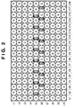
- FIG. 2 shows a portion of a pixel arrangement of the image sensor 104, which includes one of the multiple focus detection pixel groups 106.
- the pixel arrangements including the focus detection pixel groups 106 as shown in FIG. 2 are dispersedly arranged in multiple places.
- color filters are provided in Bayer arrangement, where R, G, and B respectively denote red, green, and blue. It is to be noted here that the present invention has the same advantageous effect if the arrangement of the color filters is not a Bayer arrangement.
- the rows are denoted by L1 to L10, whereas the columns are denoted by C1 to C18, and the focus detection pixels for different pupils are denoted by S1 and S2.
- the focus detection pixels S1 are arranged in the even number columns of the row L5, whereas the focus detection pixels S2 are arranged in the odd number columns of the row L6.
- the focus detection pixels S1 and S2 constitute the focus detection pixel group 106.
- the color filters for the focus detection pixels S1 and S2 need to have the same color, and is desirably transparent or G.
- the focus detection pixels S1 have the structure shown in FIG. 12A
- the focus detection pixels S2 have the structure shown in FIG. 12B . Since FIGS. 12A and 12B have been described in "Description of the Related Art", description of FIGS. 12A and 12B will be thus omitted here.
- the image forming apparatus 100 includes a focus detection unit 108 for detecting a focal point by obtaining with correlation calculation the image shifting amount between image signals output from each of the two types of focus detection pixels S1 and S2 whose optical components are symmetrically located to each other with respect to the optical axis in the focus detection pixel groups 106.
- the focus detection pixels S1 and S2 have fields of view limited by the shielding layer 503, 603.
- the image forming apparatus 100 includes a pixel interpolation unit 110 for interpolating image data for image formation corresponding to the positions of the focus detection pixels S1 and S2 from the image forming pixels near the focus detection pixels S1 and S2, depending on the output of a spatial frequency detection unit 109.
- the image forming apparatus 100 includes an image processing unit 111 for applying gamma correction, white balance adjustment, resampling, and predetermined image compression coding to image signals output from the image forming pixel group 105. Further, the image forming apparatus 100 includes a display unit 112 for displaying image data output from the image processing unit 111 and a recording unit 113 for recording the image data. Further, the image forming apparatus 100 includes an operating unit 114 for receiving operational inputs from an operator and a camera control unit 115 for controlling the entire image forming apparatus 100.
- FIG. 3 is a diagram illustrating a flowchart showing focusing operation in the image forming apparatus 100 which has the configuration described above according to the first preferred embodiment of the present invention.
- the focus detection pixels refer to the focus detection pixels S1 located in the even number columns except C18 of the row L5 and the focus detection pixels S2 located in the odd number columns except C1 of the row L6 in FIG. 2 .
- the peripheral image forming pixels refer to the pixels in the row L4 and the row L7. In addition, the peripheral image forming pixels also include G in the row L5 and G in the row L6.
- step S12 it is determined if the image signals output from the image forming pixels and read in step S11 correspond to a particular pattern or not. If so, the processing proceeds to step S13, and if not, the processing proceeds to step S14.
- step S14 signals are read out from the focus detection pixels S1 and the focus detection pixels S2 described in step S11.
- step S15 correlation calculation is carried out to obtain the defocus amount.
- the focusing area for use in correlation calculation for detecting the defocus amount the more defocus, the larger area is necessary.
- actual correlation calculation is carried out in a small area in order to avoid false detection due to perspective competition or the like.
- step S16 the focal position of the lens 101 is controlled with the lens control unit 102 in Fig. 1 depending on the defocus amount obtained in step S15, to complete the focusing processing.
- step S13 is a step executed when a particular pattern is detected from the image signals output from the image forming pixels in step S12.
- a false defocus amount may be in principle output in the correlation calculation, and in the case of a fine line pattern, errors may be caused because the focus detection pixels are dispersed with the G pixels interposed therebetween and because the positions of the focus detection pixels S1 and S2 are not strictly coincident with each other. Therefore, in step S12, a particular pattern is detected which may have an effect on the focus detection processing.
- the output of the image forming pixels near the focus detection pixels varies for each pixel indicated by dashed lines, and indicates an image signal in the case of defocusing for a periodical subject.
- An image signal as indicated by a light ray S1 is obtained from the focus detection pixel S1.
- a S1 signal refers to a signal extracted from the focusing area for actually carrying out correlation calculation.
- An image signal as indicated by a light ray S2 is obtained from the focus detection pixel S2, and a S2 signal refers to a signal extracted from the focusing area for actually carrying out correlation calculation.
- the light ray S1 and the light ray S2 are offset from each other, for the reason explained with reference to FIG. 13B . Since the light ray S1 and the light ray S2 have small pupils, the depth of field will be deep, resulting in a sharp image. In addition, the positions of the peaks will be shifted as shown in FIGS. 13A and 13B . In focus, the peaks will overlap with each other.
- the S1 signal has peaks b and c
- the S2 signal has a peak b'. Then, even though the S2 signal should be rather shifted to the left to overlap with the peak b, a similar correlation will appear as well if the S2 signal is shifted to the right to overlap with the peak c, resulting in a wrong defocus amount.
- step S13 in a case in which a particular pattern is detected such as a repetitive pattern or a fine line pattern, the setting for focus detection is changed, and the processing returns to step S11 to start the focusing processing again.
- changing the setting for focus detection which is carried out in step S13, involves the following method. First, the setting is changed in such a way that, among the multiple focus detection pixel groups 106 provided in different locations, the focus detection pixel group 106 determined as a repetitive pattern is not used, and a focus detection signal obtained from the other focus detection pixel group 106 is used.
- a method described in an earlier application filed by the applicant of the present application Japanese Patent Laid-Open No. 2000-266993 , may be used.
- a subject image formed on the focus detection pixel group 106 is a particular subject pattern which is not suitable for focus detection. Since the image forming pixels to be read out for determining the particular subject pattern include only pixels around the focus detection pixels, the particular subject pattern can be detected quickly and accurately, and the effect of the particular subject pattern on the focus detection processing can be diminished.
- the focus detection pixels S1 and S2 have no functions as image forming pixels. Thus, portions of an image corresponding to the focus detection pixels S1 and S2 have a deficiency of image data. Therefore, in the present modification, in order to reduce the effect on images, instead of the arrangement shown in FIG. 2 the focus detection pixels S1 and S2 are dispersedly arranged in the horizontal direction and the vertical direction on an image sensor 104 as shown in FIG. 5 . It is to be noted that the focusing operation in the present modification includes the same procedure as that described with reference to FIG. 3 in the first embodiment, and description of the procedure will be thus omitted here.
- FIG. 6 shows an example of image signals obtained from focus detection pixels S1 and S2 in the case of a subject with three fine lines.
- light of a light ray S1 and a light ray S2 corresponding to the fine lines is not able to be detected since the focus detection pixels S1 and S2 are arranged in pixel positions p1, p4, p7, p10, and p13.
- peaks a and b are not detected for a S1 signal
- peaks b' and c' are not detected for a S2 signal. Therefore, when correlation calculation is carried out, the correlation is maximized with the peak b and the peak a' in phase, resulting in a wrong defocus result.
- a subject image formed on the focus detection pixel group 106 is a particular subject pattern, such as a fine line, which is not suitable for focusing. Since the image forming pixels to be read out for determining the particular subject pattern include only pixels around the focus detection pixels, the particular subject pattern can be detected quickly and accurately, and the effect of the particular subject pattern on the focus detection processing can be minimized.
- the present modification allows the allover arrangement unlike the arrangement shown in FIG. 2 since the focus detection pixels are dispersedly mixed in the image sensor 104 as shown in FIG. 5 .
- the arrangement shown in FIG. 5 allows the focusing area to be changed more freely with the use of signals from the focus detection pixels from which the pattern is not detected, in a case in which a particular subject pattern such as a fine line is detected.
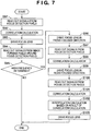
- FIG. 7 is a flowchart representing focusing operation in an image forming apparatus according to a second preferred embodiment of the present invention.
- the image forming apparatus has the configuration shown in FIG. 1 and an image sensor 104 has the pixel arrangement shown in FIG. 5 in the second embodiment.
- the second embodiment keeps from obtaining a wrong defocus amount due to a sampling error in the case of a subject with a spatial frequency higher than the period of focus detection pixels S1 and S2 arranged dispersedly.
- step S91 signals are read out from the focus detection pixels S1 and S2.
- step S92 the signals read out in step S91 are subjected to correlation calculation, and in step S93, a focus lens contained in a lens 101 is driven.
- step S94 image signals are read out from image forming pixels around the focus detection pixels S1 and S2 which have output the signals used for the correlation calculation.
- step S95 it is determined if the spatial frequency of the subject is a high-frequency component, based on the image signals read in step S94. If so, the processing proceeds to step S96, and if not, the focusing operation is completed.
- step S96 the focus lens is driven a predetermined amount from the current focus lens position (focal position) in a front-focused direction.
- step S97 signals are read out from the focus detection pixels, and in step S98, correlation calculation is carried out to store the defocus amount.
- step S99 the focus lens is driven in a rear-focused direction, which is the opposite direction to the direction in step S96.
- step S100 signals are read out from the focus detection pixels, and in step S101, correlation calculation is carried out to record the defocus amount.
- step S102 interpolation calculation is carried out with the use of the defocus amount recorded in step S98 and the defocus amount recorded in step S101, and in step S103, focus driving is carried out based on the defocus amount which is not affected by the high-frequency component.
- FIG. 8 is a diagram for explaining the technical meaning of the steps S96 though S103 described above.
- the horizontal axis indicates an actual defocus amount, which is an unknown value
- the vertical axis indicates the defocus amount calculated in step S98 or S101 (hereinafter, referred to as the detected defocus amount), which is a known value.
- the actual defocus amount and the detected defocus amount are in agreement with each other. This agreement is indicated by a broken line a with a slope of 1 in FIG. 8 .
- the actually detected defocus amount is non-linear as indicated by a solid line b, which deviates from the slope of 1.
- the defocus amount is inaccurate in focus in an area A around the origin shown in FIG. 8 .
- step S96 the focus lens is moved in the front-focused direction, and signals are read out more than once from the focus detection pixels with the focus lens in a different position (step S97).
- step S99 the focus lens is moved in the rear-focused direction and signals are read out from the focus detection pixels with the focus lens in a different position (step S100).
- step S102 interpolation calculation is carried out in such a way that the solid line b is moved toward the broken line a as shown in FIG. 8 .
- the defocus amount is calculated to move the focus lens (S103).
- the defocus amounts are obtained by defocusing back and forth, in order to reduce the contrast of subject light striking the focus detection pixels S1 and S2 of the image sensor 104 by defocusing as well as to change the phase.
- the entire subject image can be subjected to sampling even with the dispersed focus detection pixels by reading out signals from the focus detection pixels at multiple front and rear points while changing the defocus amount.
- the sampling can also be carried out with a single front and rear point.
- FIG. 9 is a flowchart representing focusing operation in an image forming apparatus according to a third preferred embodiment of the present invention. It is to be noted that, in this third embodiment, the image forming apparatus has the configuration shown in FIG. 1 and an image sensor 104 has the pixel arrangement shown in FIG. 2 or 5 .
- the focusing area for use in focus detection processing is changed in a case in which a particular pattern, such as a periodical pattern and a fine line, is detected.
- contrast autofocus is carried out in step S163, instead of phase difference autofocus carried out with the use of the focus detection pixels.
- the position of the focus lens is controlled to the position with the highest contrast, based on image signals obtained from image forming pixels, without the use of signals from the focus detection pixels S1 and S2.
- Controlling in this way can diminish the effect on focus detection processing in a case in which a fine line is detected as a particular subject pattern.
Landscapes
- Physics & Mathematics (AREA)
- Engineering & Computer Science (AREA)
- Multimedia (AREA)
- Signal Processing (AREA)
- General Physics & Mathematics (AREA)
- Optics & Photonics (AREA)
- Spectroscopy & Molecular Physics (AREA)
- Computer Vision & Pattern Recognition (AREA)
- Studio Devices (AREA)
- Focusing (AREA)
- Automatic Focus Adjustment (AREA)
Applications Claiming Priority (3)
| Application Number | Priority Date | Filing Date | Title |
|---|---|---|---|
| JP2008032349 | 2008-02-13 | ||
| JP2009022965A JP5219865B2 (ja) | 2008-02-13 | 2009-02-03 | 撮像装置及び焦点制御方法 |
| PCT/JP2009/052452 WO2009102044A1 (en) | 2008-02-13 | 2009-02-09 | Image forming apparatus |
Publications (3)
| Publication Number | Publication Date |
|---|---|
| EP2247975A1 EP2247975A1 (en) | 2010-11-10 |
| EP2247975A4 EP2247975A4 (en) | 2014-04-16 |
| EP2247975B1 true EP2247975B1 (en) | 2018-04-11 |
Family
ID=40957074
Family Applications (1)
| Application Number | Title | Priority Date | Filing Date |
|---|---|---|---|
| EP09710089.5A Not-in-force EP2247975B1 (en) | 2008-02-13 | 2009-02-09 | Image forming apparatus |
Country Status (5)
| Country | Link |
|---|---|
| US (1) | US8730373B2 (enExample) |
| EP (1) | EP2247975B1 (enExample) |
| JP (1) | JP5219865B2 (enExample) |
| CN (1) | CN101918873B (enExample) |
| WO (1) | WO2009102044A1 (enExample) |
Families Citing this family (59)
| Publication number | Priority date | Publication date | Assignee | Title |
|---|---|---|---|---|
| JP5157400B2 (ja) * | 2007-12-03 | 2013-03-06 | 株式会社ニコン | 撮像装置 |
| JP5109641B2 (ja) * | 2007-12-18 | 2012-12-26 | ソニー株式会社 | 撮像素子および撮像装置 |
| JP5241355B2 (ja) * | 2008-07-10 | 2013-07-17 | キヤノン株式会社 | 撮像装置とその制御方法 |
| JP5229060B2 (ja) * | 2009-03-31 | 2013-07-03 | ソニー株式会社 | 撮像装置および焦点検出方法 |
| JP5322783B2 (ja) * | 2009-06-05 | 2013-10-23 | キヤノン株式会社 | 撮像装置及び該撮像装置の制御方法 |
| JP2011150179A (ja) * | 2010-01-22 | 2011-08-04 | Canon Inc | オートフォーカス装置 |
| JP2011257444A (ja) | 2010-06-04 | 2011-12-22 | Olympus Corp | 撮像装置 |
| JP2012003087A (ja) * | 2010-06-17 | 2012-01-05 | Olympus Corp | 撮像装置 |
| JP2012054867A (ja) * | 2010-09-03 | 2012-03-15 | Olympus Imaging Corp | 撮像装置 |
| WO2012073728A1 (ja) * | 2010-11-30 | 2012-06-07 | 富士フイルム株式会社 | 撮像装置及びその合焦位置検出方法 |
| JP5714931B2 (ja) * | 2011-02-15 | 2015-05-07 | オリンパス株式会社 | 撮像装置 |
| CN103444185B (zh) | 2011-03-24 | 2014-10-29 | 富士胶片株式会社 | 彩色摄像元件及摄像装置 |
| JP5539583B2 (ja) * | 2011-03-24 | 2014-07-02 | 富士フイルム株式会社 | カラー撮像素子、撮像装置、及び撮像プログラム |
| JP5539584B2 (ja) * | 2011-03-24 | 2014-07-02 | 富士フイルム株式会社 | カラー撮像素子、撮像装置、及び撮像プログラム |
| CN103460103B (zh) * | 2011-03-31 | 2015-06-17 | 富士胶片株式会社 | 成像装置及其驱动方法 |
| KR101212802B1 (ko) * | 2011-03-31 | 2012-12-14 | 한국과학기술연구원 | 피사계 심도가 강조된 영상을 획득하는 방법 및 그 장치 |
| JP5967950B2 (ja) * | 2011-04-20 | 2016-08-10 | キヤノン株式会社 | 撮像素子及び撮像装置 |
| KR101777351B1 (ko) | 2011-05-16 | 2017-09-11 | 삼성전자주식회사 | 촬상 소자, 이를 이용한 디지털 촬영 장치, 오토 포커싱 방법, 및 상기 방법을 수행하기 위한 컴퓨터 판독가능 저장매체 |
| JP2013015567A (ja) * | 2011-06-30 | 2013-01-24 | Nikon Corp | 撮像装置 |
| JP5547349B2 (ja) * | 2011-09-22 | 2014-07-09 | 富士フイルム株式会社 | デジタルカメラ |
| JP5907595B2 (ja) | 2011-09-27 | 2016-04-26 | キヤノン株式会社 | 撮像装置 |
| EP2762944B1 (en) | 2011-09-28 | 2016-11-23 | Fujifilm Corporation | Imaging device and focusing control method |
| KR20130038035A (ko) * | 2011-10-07 | 2013-04-17 | 삼성전자주식회사 | 촬상소자 |
| JP5917125B2 (ja) | 2011-12-16 | 2016-05-11 | キヤノン株式会社 | 画像処理装置、画像処理方法、撮像装置および表示装置 |
| EP2624569B1 (en) * | 2012-02-06 | 2016-09-28 | Harvest Imaging bvba | Method for correcting image data from an image sensor having image pixels and non-image pixels, and image sensor implementing the same |
| CN104185983B (zh) | 2012-03-16 | 2016-10-26 | 株式会社尼康 | 摄像元件、摄像装置以及摄像系统 |
| JP6197316B2 (ja) * | 2012-03-16 | 2017-09-20 | 株式会社ニコン | 撮像素子および撮像装置 |
| JP5948102B2 (ja) * | 2012-03-26 | 2016-07-06 | 株式会社Screenホールディングス | 転写装置および転写方法 |
| CN104380167B (zh) | 2012-04-25 | 2019-03-19 | 株式会社尼康 | 焦点检测装置、焦点调节装置及相机 |
| JP2013239904A (ja) * | 2012-05-15 | 2013-11-28 | Sony Corp | 画像処理装置と画像処理方法およびプログラム |
| JP5966636B2 (ja) * | 2012-06-06 | 2016-08-10 | 株式会社ニコン | 撮像素子および撮像装置 |
| WO2013183381A1 (ja) * | 2012-06-07 | 2013-12-12 | 富士フイルム株式会社 | 撮像装置及び撮像方法 |
| JP6004768B2 (ja) * | 2012-06-14 | 2016-10-12 | キヤノン株式会社 | 焦点検出のための信号処理装置、信号処理方法およびプログラム、ならびに焦点検出装置を有する撮像装置 |
| JP5620612B2 (ja) * | 2012-06-27 | 2014-11-05 | オリンパスメディカルシステムズ株式会社 | 撮像装置および撮像システム |
| JP6045314B2 (ja) * | 2012-11-20 | 2016-12-14 | オリンパス株式会社 | 固体撮像装置、固体撮像装置の制御方法、および撮像装置 |
| DE112013005594T5 (de) * | 2012-11-22 | 2015-10-22 | Fujifilm Corporation | Abbildungsvorrichtung, Unschärfebetrag-Berechnungsverfahren und Objektivvorrichtung |
| JP2014160930A (ja) * | 2013-02-19 | 2014-09-04 | Sony Corp | 固体撮像素子およびその駆動方法、並びに電子機器 |
| JP6052057B2 (ja) * | 2013-05-22 | 2016-12-27 | ソニー株式会社 | 信号処理装置および信号処理方法、固体撮像装置、並びに、電子機器 |
| JP6089972B2 (ja) * | 2013-05-29 | 2017-03-08 | 株式会社ニコン | 撮像装置 |
| WO2015045785A1 (ja) * | 2013-09-30 | 2015-04-02 | 富士フイルム株式会社 | 画像処理装置、撮像装置、画像処理方法及び画像処理プログラム |
| JP2015102735A (ja) * | 2013-11-26 | 2015-06-04 | 株式会社ニコン | 焦点検出装置および撮像装置 |
| JP2016009043A (ja) | 2014-06-24 | 2016-01-18 | ソニー株式会社 | イメージセンサ、演算方法、および電子装置 |
| JP2016015009A (ja) * | 2014-07-02 | 2016-01-28 | ソニー株式会社 | 情報処理システム、情報処理端末、および情報処理方法 |
| CN105259729B (zh) * | 2014-07-17 | 2019-10-18 | 宁波舜宇光电信息有限公司 | 一种af快速对焦方法 |
| JP6530593B2 (ja) * | 2014-08-11 | 2019-06-12 | キヤノン株式会社 | 撮像装置及びその制御方法、記憶媒体 |
| KR102283423B1 (ko) | 2014-12-18 | 2021-07-30 | 엘지이노텍 주식회사 | 영상 획득 장치 및 이를 포함하는 휴대용 단말기와 그 장치의 영상 획득 방법 |
| US9973678B2 (en) | 2015-01-14 | 2018-05-15 | Invisage Technologies, Inc. | Phase-detect autofocus |
| TWI565323B (zh) * | 2015-09-02 | 2017-01-01 | 原相科技股份有限公司 | 分辨前景的成像裝置及其運作方法、以及影像感測器 |
| US9420164B1 (en) * | 2015-09-24 | 2016-08-16 | Qualcomm Incorporated | Phase detection autofocus noise reduction |
| US9804357B2 (en) | 2015-09-25 | 2017-10-31 | Qualcomm Incorporated | Phase detection autofocus using masked and unmasked photodiodes |
| JPWO2017154366A1 (ja) | 2016-03-11 | 2019-01-17 | ソニー株式会社 | ローパスフィルタ制御装置、およびローパスフィルタ制御方法、ならびに撮像装置 |
| JP2018010245A (ja) | 2016-07-15 | 2018-01-18 | キヤノン株式会社 | 信号処理装置、その制御方法 |
| JP6900161B2 (ja) * | 2016-09-14 | 2021-07-07 | キヤノン株式会社 | 焦点調節装置及び撮像装置 |
| US10284800B2 (en) * | 2016-10-21 | 2019-05-07 | Canon Kabushiki Kaisha | Solid-state image pickup element, method of controlling a solid-state image pickup element, and image pickup apparatus |
| JP2018097176A (ja) * | 2016-12-14 | 2018-06-21 | オリンパス株式会社 | 焦点調節装置および焦点調節方法 |
| WO2019065554A1 (ja) * | 2017-09-28 | 2019-04-04 | 富士フイルム株式会社 | 撮像装置、情報取得方法及び情報取得プログラム |
| WO2019065555A1 (ja) | 2017-09-28 | 2019-04-04 | 富士フイルム株式会社 | 撮像装置、情報取得方法及び情報取得プログラム |
| JP7433793B2 (ja) | 2019-07-19 | 2024-02-20 | キヤノン株式会社 | 撮像装置およびその制御方法 |
| EP4529150A4 (en) * | 2022-05-20 | 2025-06-18 | Beijing Xiaomi Mobile Software Co., Ltd. | CAMERA AND FOCUS CONTROL PROGRAM |
Citations (1)
| Publication number | Priority date | Publication date | Assignee | Title |
|---|---|---|---|---|
| EP1843574A1 (en) * | 2006-04-04 | 2007-10-10 | Nikon Corporation | Camera comprising an automatic selection of an autofocus area |
Family Cites Families (25)
| Publication number | Priority date | Publication date | Assignee | Title |
|---|---|---|---|---|
| JPH01147512A (ja) * | 1987-12-04 | 1989-06-09 | Konica Corp | 自動焦点調節装置 |
| JPH01216306A (ja) | 1988-02-24 | 1989-08-30 | Canon Inc | 撮像手段を有した焦点検出装置 |
| JPH0743605A (ja) * | 1993-08-02 | 1995-02-14 | Minolta Co Ltd | 自動焦点装置 |
| JPH07199052A (ja) | 1993-12-28 | 1995-08-04 | Olympus Optical Co Ltd | 焦点検出方法および距離測定方法 |
| JP3592147B2 (ja) | 1998-08-20 | 2004-11-24 | キヤノン株式会社 | 固体撮像装置 |
| US6332061B1 (en) | 1999-03-18 | 2001-12-18 | Canon Kabushiki Kaisha | Focus detecting device and automatic focusing camera |
| US6819360B1 (en) * | 1999-04-01 | 2004-11-16 | Olympus Corporation | Image pickup element and apparatus for focusing |
| JP4541479B2 (ja) | 2000-01-31 | 2010-09-08 | キヤノン株式会社 | 測距装置及びカメラ |
| US6766112B2 (en) * | 2000-04-03 | 2004-07-20 | Nikon Corporation | Focal point detection apparatus and focal point detection module |
| US20020025156A1 (en) * | 2000-04-03 | 2002-02-28 | Nikon Corporation | Focal point detection apparatus and focal point detection module |
| JP4908668B2 (ja) * | 2000-04-19 | 2012-04-04 | キヤノン株式会社 | 焦点検出装置 |
| JP2003279348A (ja) * | 2002-03-26 | 2003-10-02 | Seiko Precision Inc | 位相差検出方法、位相差検出装置、測距装置および撮像装置 |
| JP2005128292A (ja) * | 2003-10-24 | 2005-05-19 | Nikon Corp | 焦点検出装置およびカメラ |
| EP1684503B1 (en) * | 2005-01-25 | 2016-01-13 | Canon Kabushiki Kaisha | Camera and autofocus control method therefor |
| JP4773769B2 (ja) * | 2005-08-17 | 2011-09-14 | キヤノン株式会社 | 焦点検出装置 |
| US7751700B2 (en) * | 2006-03-01 | 2010-07-06 | Nikon Corporation | Focus adjustment device, imaging device and focus adjustment method |
| JP2007264299A (ja) * | 2006-03-28 | 2007-10-11 | Olympus Imaging Corp | 焦点調節装置 |
| US7711261B2 (en) | 2006-04-11 | 2010-05-04 | Nikon Corporation | Imaging device, camera and image processing method |
| JP4935162B2 (ja) * | 2006-04-11 | 2012-05-23 | 株式会社ニコン | 撮像装置、カメラおよび画像処理方法 |
| JP5066893B2 (ja) * | 2006-05-17 | 2012-11-07 | 株式会社ニコン | 相関演算方法、相関演算装置、焦点検出装置および撮像装置 |
| US7586588B2 (en) | 2006-05-17 | 2009-09-08 | Nikon Corporation | Correlation operation method, correlation operation device, focus detection device and imaging device |
| WO2008001575A1 (fr) * | 2006-06-28 | 2008-01-03 | Nikon Corporation | Dispositif de localisation, dispositif de mise au point automatique et appareil photographique |
| JP2008026788A (ja) * | 2006-07-25 | 2008-02-07 | Canon Inc | 撮像装置及びフォーカス制御方法 |
| JP5264131B2 (ja) * | 2007-09-14 | 2013-08-14 | キヤノン株式会社 | 撮像装置 |
| US20110304765A1 (en) * | 2009-02-18 | 2011-12-15 | Yogo Takanori | Imaging apparatus |
-
2009
- 2009-02-03 JP JP2009022965A patent/JP5219865B2/ja not_active Expired - Fee Related
- 2009-02-09 WO PCT/JP2009/052452 patent/WO2009102044A1/en not_active Ceased
- 2009-02-09 US US12/745,564 patent/US8730373B2/en active Active
- 2009-02-09 CN CN2009801026025A patent/CN101918873B/zh not_active Expired - Fee Related
- 2009-02-09 EP EP09710089.5A patent/EP2247975B1/en not_active Not-in-force
Patent Citations (1)
| Publication number | Priority date | Publication date | Assignee | Title |
|---|---|---|---|---|
| EP1843574A1 (en) * | 2006-04-04 | 2007-10-10 | Nikon Corporation | Camera comprising an automatic selection of an autofocus area |
Also Published As
| Publication number | Publication date |
|---|---|
| CN101918873A (zh) | 2010-12-15 |
| US8730373B2 (en) | 2014-05-20 |
| EP2247975A4 (en) | 2014-04-16 |
| EP2247975A1 (en) | 2010-11-10 |
| WO2009102044A1 (en) | 2009-08-20 |
| US20100302433A1 (en) | 2010-12-02 |
| JP5219865B2 (ja) | 2013-06-26 |
| JP2009217252A (ja) | 2009-09-24 |
| CN101918873B (zh) | 2012-07-18 |
Similar Documents
| Publication | Publication Date | Title |
|---|---|---|
| EP2247975B1 (en) | Image forming apparatus | |
| US9313469B2 (en) | Image capturing apparatus and method of controlling the same | |
| JP5361535B2 (ja) | 撮像装置 | |
| EP2590023B1 (en) | Imaging device and imaging method | |
| JP4952060B2 (ja) | 撮像装置 | |
| JP5572765B2 (ja) | 固体撮像素子、撮像装置、及び合焦制御方法 | |
| JP5629832B2 (ja) | 撮像装置及び位相差画素の感度比算出方法 | |
| US8902349B2 (en) | Image pickup apparatus | |
| JP4983271B2 (ja) | 撮像装置 | |
| US8736742B2 (en) | Image pickup apparatus that performs automatic focus control and control method for the image pickup apparatus | |
| JP5547338B2 (ja) | カラー撮像素子、撮像装置、及び撮像プログラム | |
| JP5539585B2 (ja) | カラー撮像素子、撮像装置、及び撮像プログラム | |
| WO2012128153A1 (ja) | カラー撮像素子、撮像装置、及び撮像装置の制御プログラム | |
| JP4858179B2 (ja) | 焦点検出装置および撮像装置 | |
| WO2012073727A1 (ja) | 撮像装置及びその合焦位置検出方法 | |
| US9602716B2 (en) | Focus-detection device, method for controlling the same, and image capture apparatus | |
| JP5045007B2 (ja) | 撮像装置 | |
| US8792048B2 (en) | Focus detection device and image capturing apparatus provided with the same | |
| JP5831070B2 (ja) | 撮像装置 | |
| JP2012242549A (ja) | 撮像装置 |
Legal Events
| Date | Code | Title | Description |
|---|---|---|---|
| PUAI | Public reference made under article 153(3) epc to a published international application that has entered the european phase |
Free format text: ORIGINAL CODE: 0009012 |
|
| 17P | Request for examination filed |
Effective date: 20100913 |
|
| AK | Designated contracting states |
Kind code of ref document: A1 Designated state(s): AT BE BG CH CY CZ DE DK EE ES FI FR GB GR HR HU IE IS IT LI LT LU LV MC MK MT NL NO PL PT RO SE SI SK TR |
|
| AX | Request for extension of the european patent |
Extension state: AL BA RS |
|
| DAX | Request for extension of the european patent (deleted) | ||
| A4 | Supplementary search report drawn up and despatched |
Effective date: 20140318 |
|
| RIC1 | Information provided on ipc code assigned before grant |
Ipc: G02B 7/34 20060101ALI20140312BHEP Ipc: H04N 9/04 20060101ALI20140312BHEP Ipc: G03B 13/36 20060101ALI20140312BHEP Ipc: H04N 5/232 20060101ALI20140312BHEP Ipc: G02B 7/28 20060101AFI20140312BHEP Ipc: H04N 5/369 20110101ALI20140312BHEP Ipc: G02B 7/36 20060101ALI20140312BHEP Ipc: H04N 5/335 20110101ALI20140312BHEP |
|
| 17Q | First examination report despatched |
Effective date: 20151130 |
|
| GRAP | Despatch of communication of intention to grant a patent |
Free format text: ORIGINAL CODE: EPIDOSNIGR1 |
|
| STAA | Information on the status of an ep patent application or granted ep patent |
Free format text: STATUS: GRANT OF PATENT IS INTENDED |
|
| INTG | Intention to grant announced |
Effective date: 20171013 |
|
| GRAS | Grant fee paid |
Free format text: ORIGINAL CODE: EPIDOSNIGR3 |
|
| GRAA | (expected) grant |
Free format text: ORIGINAL CODE: 0009210 |
|
| STAA | Information on the status of an ep patent application or granted ep patent |
Free format text: STATUS: THE PATENT HAS BEEN GRANTED |
|
| AK | Designated contracting states |
Kind code of ref document: B1 Designated state(s): AT BE BG CH CY CZ DE DK EE ES FI FR GB GR HR HU IE IS IT LI LT LU LV MC MK MT NL NO PL PT RO SE SI SK TR |
|
| REG | Reference to a national code |
Ref country code: GB Ref legal event code: FG4D |
|
| REG | Reference to a national code |
Ref country code: CH Ref legal event code: EP |
|
| REG | Reference to a national code |
Ref country code: AT Ref legal event code: REF Ref document number: 988649 Country of ref document: AT Kind code of ref document: T Effective date: 20180415 |
|
| REG | Reference to a national code |
Ref country code: IE Ref legal event code: FG4D |
|
| REG | Reference to a national code |
Ref country code: DE Ref legal event code: R096 Ref document number: 602009051700 Country of ref document: DE |
|
| REG | Reference to a national code |
Ref country code: NL Ref legal event code: MP Effective date: 20180411 |
|
| REG | Reference to a national code |
Ref country code: LT Ref legal event code: MG4D |
|
| PG25 | Lapsed in a contracting state [announced via postgrant information from national office to epo] |
Ref country code: NL Free format text: LAPSE BECAUSE OF FAILURE TO SUBMIT A TRANSLATION OF THE DESCRIPTION OR TO PAY THE FEE WITHIN THE PRESCRIBED TIME-LIMIT Effective date: 20180411 |
|
| PG25 | Lapsed in a contracting state [announced via postgrant information from national office to epo] |
Ref country code: BG Free format text: LAPSE BECAUSE OF FAILURE TO SUBMIT A TRANSLATION OF THE DESCRIPTION OR TO PAY THE FEE WITHIN THE PRESCRIBED TIME-LIMIT Effective date: 20180711 Ref country code: LT Free format text: LAPSE BECAUSE OF FAILURE TO SUBMIT A TRANSLATION OF THE DESCRIPTION OR TO PAY THE FEE WITHIN THE PRESCRIBED TIME-LIMIT Effective date: 20180411 Ref country code: NO Free format text: LAPSE BECAUSE OF FAILURE TO SUBMIT A TRANSLATION OF THE DESCRIPTION OR TO PAY THE FEE WITHIN THE PRESCRIBED TIME-LIMIT Effective date: 20180711 Ref country code: FI Free format text: LAPSE BECAUSE OF FAILURE TO SUBMIT A TRANSLATION OF THE DESCRIPTION OR TO PAY THE FEE WITHIN THE PRESCRIBED TIME-LIMIT Effective date: 20180411 Ref country code: SE Free format text: LAPSE BECAUSE OF FAILURE TO SUBMIT A TRANSLATION OF THE DESCRIPTION OR TO PAY THE FEE WITHIN THE PRESCRIBED TIME-LIMIT Effective date: 20180411 Ref country code: ES Free format text: LAPSE BECAUSE OF FAILURE TO SUBMIT A TRANSLATION OF THE DESCRIPTION OR TO PAY THE FEE WITHIN THE PRESCRIBED TIME-LIMIT Effective date: 20180411 Ref country code: PL Free format text: LAPSE BECAUSE OF FAILURE TO SUBMIT A TRANSLATION OF THE DESCRIPTION OR TO PAY THE FEE WITHIN THE PRESCRIBED TIME-LIMIT Effective date: 20180411 |
|
| PG25 | Lapsed in a contracting state [announced via postgrant information from national office to epo] |
Ref country code: LV Free format text: LAPSE BECAUSE OF FAILURE TO SUBMIT A TRANSLATION OF THE DESCRIPTION OR TO PAY THE FEE WITHIN THE PRESCRIBED TIME-LIMIT Effective date: 20180411 Ref country code: GR Free format text: LAPSE BECAUSE OF FAILURE TO SUBMIT A TRANSLATION OF THE DESCRIPTION OR TO PAY THE FEE WITHIN THE PRESCRIBED TIME-LIMIT Effective date: 20180712 Ref country code: HR Free format text: LAPSE BECAUSE OF FAILURE TO SUBMIT A TRANSLATION OF THE DESCRIPTION OR TO PAY THE FEE WITHIN THE PRESCRIBED TIME-LIMIT Effective date: 20180411 |
|
| REG | Reference to a national code |
Ref country code: AT Ref legal event code: MK05 Ref document number: 988649 Country of ref document: AT Kind code of ref document: T Effective date: 20180411 |
|
| PG25 | Lapsed in a contracting state [announced via postgrant information from national office to epo] |
Ref country code: PT Free format text: LAPSE BECAUSE OF FAILURE TO SUBMIT A TRANSLATION OF THE DESCRIPTION OR TO PAY THE FEE WITHIN THE PRESCRIBED TIME-LIMIT Effective date: 20180813 |
|
| REG | Reference to a national code |
Ref country code: DE Ref legal event code: R097 Ref document number: 602009051700 Country of ref document: DE |
|
| PG25 | Lapsed in a contracting state [announced via postgrant information from national office to epo] |
Ref country code: RO Free format text: LAPSE BECAUSE OF FAILURE TO SUBMIT A TRANSLATION OF THE DESCRIPTION OR TO PAY THE FEE WITHIN THE PRESCRIBED TIME-LIMIT Effective date: 20180411 Ref country code: SK Free format text: LAPSE BECAUSE OF FAILURE TO SUBMIT A TRANSLATION OF THE DESCRIPTION OR TO PAY THE FEE WITHIN THE PRESCRIBED TIME-LIMIT Effective date: 20180411 Ref country code: CZ Free format text: LAPSE BECAUSE OF FAILURE TO SUBMIT A TRANSLATION OF THE DESCRIPTION OR TO PAY THE FEE WITHIN THE PRESCRIBED TIME-LIMIT Effective date: 20180411 Ref country code: DK Free format text: LAPSE BECAUSE OF FAILURE TO SUBMIT A TRANSLATION OF THE DESCRIPTION OR TO PAY THE FEE WITHIN THE PRESCRIBED TIME-LIMIT Effective date: 20180411 Ref country code: AT Free format text: LAPSE BECAUSE OF FAILURE TO SUBMIT A TRANSLATION OF THE DESCRIPTION OR TO PAY THE FEE WITHIN THE PRESCRIBED TIME-LIMIT Effective date: 20180411 Ref country code: EE Free format text: LAPSE BECAUSE OF FAILURE TO SUBMIT A TRANSLATION OF THE DESCRIPTION OR TO PAY THE FEE WITHIN THE PRESCRIBED TIME-LIMIT Effective date: 20180411 |
|
| PLBE | No opposition filed within time limit |
Free format text: ORIGINAL CODE: 0009261 |
|
| STAA | Information on the status of an ep patent application or granted ep patent |
Free format text: STATUS: NO OPPOSITION FILED WITHIN TIME LIMIT |
|
| PG25 | Lapsed in a contracting state [announced via postgrant information from national office to epo] |
Ref country code: IT Free format text: LAPSE BECAUSE OF FAILURE TO SUBMIT A TRANSLATION OF THE DESCRIPTION OR TO PAY THE FEE WITHIN THE PRESCRIBED TIME-LIMIT Effective date: 20180411 |
|
| 26N | No opposition filed |
Effective date: 20190114 |
|
| PG25 | Lapsed in a contracting state [announced via postgrant information from national office to epo] |
Ref country code: SI Free format text: LAPSE BECAUSE OF FAILURE TO SUBMIT A TRANSLATION OF THE DESCRIPTION OR TO PAY THE FEE WITHIN THE PRESCRIBED TIME-LIMIT Effective date: 20180411 |
|
| REG | Reference to a national code |
Ref country code: CH Ref legal event code: PL |
|
| GBPC | Gb: european patent ceased through non-payment of renewal fee |
Effective date: 20190209 |
|
| PG25 | Lapsed in a contracting state [announced via postgrant information from national office to epo] |
Ref country code: LU Free format text: LAPSE BECAUSE OF NON-PAYMENT OF DUE FEES Effective date: 20190209 Ref country code: MC Free format text: LAPSE BECAUSE OF FAILURE TO SUBMIT A TRANSLATION OF THE DESCRIPTION OR TO PAY THE FEE WITHIN THE PRESCRIBED TIME-LIMIT Effective date: 20180411 |
|
| REG | Reference to a national code |
Ref country code: BE Ref legal event code: MM Effective date: 20190228 |
|
| REG | Reference to a national code |
Ref country code: IE Ref legal event code: MM4A |
|
| PG25 | Lapsed in a contracting state [announced via postgrant information from national office to epo] |
Ref country code: LI Free format text: LAPSE BECAUSE OF NON-PAYMENT OF DUE FEES Effective date: 20190228 Ref country code: CH Free format text: LAPSE BECAUSE OF NON-PAYMENT OF DUE FEES Effective date: 20190228 |
|
| PG25 | Lapsed in a contracting state [announced via postgrant information from national office to epo] |
Ref country code: GB Free format text: LAPSE BECAUSE OF NON-PAYMENT OF DUE FEES Effective date: 20190209 Ref country code: IE Free format text: LAPSE BECAUSE OF NON-PAYMENT OF DUE FEES Effective date: 20190209 |
|
| PG25 | Lapsed in a contracting state [announced via postgrant information from national office to epo] |
Ref country code: FR Free format text: LAPSE BECAUSE OF NON-PAYMENT OF DUE FEES Effective date: 20190228 Ref country code: BE Free format text: LAPSE BECAUSE OF NON-PAYMENT OF DUE FEES Effective date: 20190228 |
|
| PG25 | Lapsed in a contracting state [announced via postgrant information from national office to epo] |
Ref country code: TR Free format text: LAPSE BECAUSE OF FAILURE TO SUBMIT A TRANSLATION OF THE DESCRIPTION OR TO PAY THE FEE WITHIN THE PRESCRIBED TIME-LIMIT Effective date: 20180411 |
|
| PG25 | Lapsed in a contracting state [announced via postgrant information from national office to epo] |
Ref country code: MT Free format text: LAPSE BECAUSE OF NON-PAYMENT OF DUE FEES Effective date: 20190209 |
|
| PGFP | Annual fee paid to national office [announced via postgrant information from national office to epo] |
Ref country code: DE Payment date: 20200429 Year of fee payment: 12 |
|
| PG25 | Lapsed in a contracting state [announced via postgrant information from national office to epo] |
Ref country code: CY Free format text: LAPSE BECAUSE OF FAILURE TO SUBMIT A TRANSLATION OF THE DESCRIPTION OR TO PAY THE FEE WITHIN THE PRESCRIBED TIME-LIMIT Effective date: 20180411 |
|
| PG25 | Lapsed in a contracting state [announced via postgrant information from national office to epo] |
Ref country code: IS Free format text: LAPSE BECAUSE OF FAILURE TO SUBMIT A TRANSLATION OF THE DESCRIPTION OR TO PAY THE FEE WITHIN THE PRESCRIBED TIME-LIMIT Effective date: 20180811 |
|
| PG25 | Lapsed in a contracting state [announced via postgrant information from national office to epo] |
Ref country code: HU Free format text: LAPSE BECAUSE OF FAILURE TO SUBMIT A TRANSLATION OF THE DESCRIPTION OR TO PAY THE FEE WITHIN THE PRESCRIBED TIME-LIMIT; INVALID AB INITIO Effective date: 20090209 |
|
| REG | Reference to a national code |
Ref country code: DE Ref legal event code: R119 Ref document number: 602009051700 Country of ref document: DE |
|
| PG25 | Lapsed in a contracting state [announced via postgrant information from national office to epo] |
Ref country code: DE Free format text: LAPSE BECAUSE OF NON-PAYMENT OF DUE FEES Effective date: 20210901 |
|
| PG25 | Lapsed in a contracting state [announced via postgrant information from national office to epo] |
Ref country code: MK Free format text: LAPSE BECAUSE OF FAILURE TO SUBMIT A TRANSLATION OF THE DESCRIPTION OR TO PAY THE FEE WITHIN THE PRESCRIBED TIME-LIMIT Effective date: 20180411 |