EP2241408B1 - Seitenhandgriff - Google Patents
Seitenhandgriff Download PDFInfo
- Publication number
- EP2241408B1 EP2241408B1 EP10157822A EP10157822A EP2241408B1 EP 2241408 B1 EP2241408 B1 EP 2241408B1 EP 10157822 A EP10157822 A EP 10157822A EP 10157822 A EP10157822 A EP 10157822A EP 2241408 B1 EP2241408 B1 EP 2241408B1
- Authority
- EP
- European Patent Office
- Prior art keywords
- grip element
- grip
- fastening means
- bearing
- side handgrip
- Prior art date
- Legal status (The legal status is an assumption and is not a legal conclusion. Google has not performed a legal analysis and makes no representation as to the accuracy of the status listed.)
- Active
Links
- 230000005484 gravity Effects 0.000 claims description 6
- 230000000284 resting effect Effects 0.000 claims 2
- 238000013016 damping Methods 0.000 description 3
- 230000000694 effects Effects 0.000 description 2
- 230000033001 locomotion Effects 0.000 description 2
- 241001422033 Thestylus Species 0.000 description 1
- 239000006096 absorbing agent Substances 0.000 description 1
- 230000005540 biological transmission Effects 0.000 description 1
- 239000002131 composite material Substances 0.000 description 1
- 230000001066 destructive effect Effects 0.000 description 1
- 239000013013 elastic material Substances 0.000 description 1
- 210000005224 forefinger Anatomy 0.000 description 1
- 239000000463 material Substances 0.000 description 1
- 238000009527 percussion Methods 0.000 description 1
- 238000007789 sealing Methods 0.000 description 1
- 238000010008 shearing Methods 0.000 description 1
- 238000010025 steaming Methods 0.000 description 1
- 210000003813 thumb Anatomy 0.000 description 1
Images


Classifications
-
- B—PERFORMING OPERATIONS; TRANSPORTING
- B25—HAND TOOLS; PORTABLE POWER-DRIVEN TOOLS; MANIPULATORS
- B25F—COMBINATION OR MULTI-PURPOSE TOOLS NOT OTHERWISE PROVIDED FOR; DETAILS OR COMPONENTS OF PORTABLE POWER-DRIVEN TOOLS NOT PARTICULARLY RELATED TO THE OPERATIONS PERFORMED AND NOT OTHERWISE PROVIDED FOR
- B25F5/00—Details or components of portable power-driven tools not particularly related to the operations performed and not otherwise provided for
- B25F5/006—Vibration damping means
-
- B—PERFORMING OPERATIONS; TRANSPORTING
- B25—HAND TOOLS; PORTABLE POWER-DRIVEN TOOLS; MANIPULATORS
- B25D—PERCUSSIVE TOOLS
- B25D17/00—Details of, or accessories for, portable power-driven percussive tools
- B25D17/04—Handles; Handle mountings
- B25D17/043—Handles resiliently mounted relative to the hammer housing
-
- B—PERFORMING OPERATIONS; TRANSPORTING
- B25—HAND TOOLS; PORTABLE POWER-DRIVEN TOOLS; MANIPULATORS
- B25F—COMBINATION OR MULTI-PURPOSE TOOLS NOT OTHERWISE PROVIDED FOR; DETAILS OR COMPONENTS OF PORTABLE POWER-DRIVEN TOOLS NOT PARTICULARLY RELATED TO THE OPERATIONS PERFORMED AND NOT OTHERWISE PROVIDED FOR
- B25F5/00—Details or components of portable power-driven tools not particularly related to the operations performed and not otherwise provided for
- B25F5/02—Construction of casings, bodies or handles
- B25F5/025—Construction of casings, bodies or handles with torque reaction bars for rotary tools
- B25F5/026—Construction of casings, bodies or handles with torque reaction bars for rotary tools in the form of an auxiliary handle
-
- B—PERFORMING OPERATIONS; TRANSPORTING
- B25—HAND TOOLS; PORTABLE POWER-DRIVEN TOOLS; MANIPULATORS
- B25D—PERCUSSIVE TOOLS
- B25D2217/00—Details of, or accessories for, portable power-driven percussive tools
- B25D2217/0073—Arrangements for damping of the reaction force
- B25D2217/0076—Arrangements for damping of the reaction force by use of counterweights
- B25D2217/0092—Arrangements for damping of the reaction force by use of counterweights being spring-mounted
-
- B—PERFORMING OPERATIONS; TRANSPORTING
- B25—HAND TOOLS; PORTABLE POWER-DRIVEN TOOLS; MANIPULATORS
- B25D—PERCUSSIVE TOOLS
- B25D2250/00—General details of portable percussive tools; Components used in portable percussive tools
- B25D2250/245—Spatial arrangement of components of the tool relative to each other
Definitions
- the present invention relates to a side handle for a hand tool according to the preamble of claim 1 and as from GB 2 451 745 A known.
- Another side handle is from the EP 1 905 546 A2 known.
- Hand tool machines transmit vibrations to a side handle.
- Damping elements in the side handle are intended to reduce an amplitude of the vibrations on a gripping surface.
- US 5,157,807 A describes such a handle.
- a handle according to the GB 2 080 920 A has an anchor rod, one end of which is attachable to a hand tool. At the other end, a handle is pivotally applied by means of two mandrels.
- the vibration-damped side handle is a compromise between the ability to transfer forces of the user to the power tool and to reduce vibrations from the hand tool on the gripping surface. Transferring forces requires stiff, unyielding elements. Steaming, especially low frequency vibrations, requires soft, compliant elements.
- the inertia of the side handle may be increased by increasing its mass to improve damping. However, this increases the weight of the power tool.
- the inventive side handle for a hand tool includes a handle member and a fastening means for securing the side handle to the power tool.
- the gripping element and the fastening means are pivotable relative to each other about an axis of rotation.
- the axis of rotation runs perpendicular to a longitudinal axis of the grip element and extends through an end region of the grip element facing away from the attachment means.
- the user can grip the handle member near the end portion.
- the forces exerted by him, acting perpendicular to the handle element forces are transmitted to the fastener.
- Vibrations introduced via the fastener cause the handle member to vibrate.
- the amplitude of the vibrations is transmitted in a vibratory motion and dissipated their energy and / or the amplitude out of phase delivered to the vibrations again.
- a restoring element is provided for driving the grip element back into a basic position with respect to the attachment means.
- the return element can be tuned to the frequencies of the vibrations that occur, so that the side handle acts as a absorber.
- a damper is resonantly excited by the vibrations and gives the vibrations phase-delayed and thus destructive to newly occurring vibrations again.
- the handle member has a bearing that defines the axis of rotation about which the handle member is swingable, and a connector connects the bearing with the fastener.
- the connecting element can be stiff.
- the connecting element is arranged within the handle bar.
- the bearing has at least one elastic element, which couples the connecting element with the handle element. Compared to a sliding bearing with accurately fitting bearing elements, the bearing described can be constructed simpler.
- the elastic element can enclose the connecting element in an annular manner.
- a restoring element is provided on an end region of the gripping element facing the fastening means, which engages on the connecting element and the gripping element.
- the return element may be formed by a spring.
- the return element may be formed by a helical spring or spiral spring, which bears against a first surface of a first turn on the stylus element and with a second surface of a second turn on the connecting element. The second surface may be remote from the connecting element.
- One embodiment provides that an additional mass is attached to an end region of the grip element facing the attachment means.
- the additional mass increases the torque of the oscillating grip element. Due to the leverage effect is already achieved a large effect at a comparatively low mass.
- An embodiment provides that a center of gravity of the grip element lies outside a predetermined gripping surface.
- Fig. 1 shows a hand tool 10.
- the hand tool 10 may, for example, a drill, a chisel hammer, an electric screwdriver or a disc grinder instead of the percussion drill shown as an example.
- the hand tool 10 has a handle 11 and near a tool holder 12 an additional side handle 13.
- the side handle 13 is preferably detachably attachable to the power tool 10.
- the side handle 13 facilitates one User of the power tool 10 by a two-handed holding, especially in heavy power tool 10, a guide of the power tool 10th
- Fig. 2 shows in cross section an embodiment of the side handle 13.
- the side handle 13 has a clamping band 14, by means of which the side handle 13 can be fastened to the hand tool 10.
- the strap 14 defines an orientation of the side handle 13 along an axis 15.
- the axis 15 may be parallel to a direction of impact or effective direction 16 of the handheld power tool 10.
- the side handle 13 can also be fastened to the handheld power tool 10 via a screw connection or another suitable fastening means.
- the side handle 13 includes a handle bar 17 having a gripping surface 18.
- the gripping surface 18 may at least partially engage a user.
- a skin-friendly plastic may be injected around the handle bar 17, which forms the gripping surface 18.
- the gripping surface 18 may be formed according to the anatomical shape of a hand. A system for the grasping thumb and forefinger can thus be specified.
- the handle bar 17 may be formed hollow as a grip sleeve 19.
- the handle bar 17 is approximately perpendicular to the axis 15.
- a first end 20 of the handle bar 17 faces the strap 14, a second end 21 of the handle bar 17 is remote from the strap 14.
- the handle bar 17 is pivotally mounted relative to the clamping band 14 about an axis of rotation 22.
- the axis of rotation 22 extends through the second end 21 of the handle bar 17 and is substantially parallel to the axis 15.
- a bearing 23 is inserted at the second end 21.
- the bearing 23 has a first bearing element 24 and a second bearing element 25 which are rotatable relative to one another about at least the axis of rotation 22.
- the first bearing element 24 is torsionally rigid with the handle bar 17, for example, the grip sleeve 19, connected.
- the second bearing element 25 is connected via a connecting rod 26 with the clamping band 14.
- the connecting rod 26 may be made of a rigid material.
- the connecting rod 26 may be disposed within the grip sleeve 19.
- the first end 20 of the handle bar 17 is spaced from the strap 14 such that the first end 20 is movable with respect to the strap 14 in a rotational movement about the axis of rotation 22.
- a sealing element 27, for example a felt ring or a bellows, may be provided on the tension band 14, which seals a gap 28 between the tension band 14 and the first end 20.
- a spring 29 is provided at the first end 20 of the handle bar 17.
- the spring 29 exerts a force 30 substantially along the axis 15 of the connecting rod 26 on the handle bar 17.
- the spring 29 acts as a restoring element, which drives the handle bar 17 back into a basic position after a pivoting of the handle bar 17 relative to the connecting rod 26.
- the spring 29 can exert pressure and / or tensile forces.
- the spring 29 is designed to exert no force in a parallel position of handle bar 17 and connecting rod 26.
- a mass body 31 can be arranged.
- a mass of the mass body 31 is chosen such that the center of gravity 32 of the handle bar 17 is outside the gripping surface 18.
- the mass body 31 can be integrated within a slip guard 33 at the first end 20.
- a deflection of the handle bar 17 can be limited by stop elements 34.
- the stop element 34 may be formed, for example, by a projection on the connecting rod 26 or within the handle bar 17. The damping can in particular be prevented when the user pulls the power tool 10 away from a workpiece.
- the stop element 34 can be arranged asymmetrically with respect to the axis 15 on a side which points in the direction of action 16 of the handheld power tool 10 when the side handle 13 is fastened to the handheld power tool 10.
- An elastic buffer may be arranged on the stop element 34 or on a surface 36 opposite the stop element 34.
- Fig. 3 shows a further embodiment of a side handle 38.
- the structure differs from that associated with Fig. 2 described side handle 13 among other things in the execution of the bearing 39 and the return element 40.
- the two embodiments can be combined with each other, for example by replacing the bearing and / or the return element.
- the bearing 39 consists of a first bearing shell 41, a second bearing shell 42 and a spring element 43.
- the first bearing shell 41 is formed by an end piece 44 of the connecting rod 26.
- a recess 45 for example, an annular or star-shaped recess 45 is introduced.
- the second bearing shell 42 may be formed by an inner contour 46 of the second end 21.
- the spring element 43 may be formed by elastic elements, for example a ring made of elastic plastic. The spring element or the spring elements engage in the opposite recesses 45, 46 of the two bearing shells 41, 42.
- Fig. 4 shows a possible embodiment of the elastic member 47 and the bearing shells 41, 42 in cross section along the plane AA Fig. 3
- the bearing to be designed as a solid-body joint 48.
- the solid-state joint 48 is as a cutout in Fig. 5 shown.
- the connecting rod 49 is made of an elastic material.
- the second end 21 of the handle bar 17 with the connecting rod 49 is positively and / or non-positively applied, for example by a clamping or screw connection.
- the connecting rod 49 is thinner in a region 51.
- the cross-sectional area in the thinner area 51 is selected such that the connecting bar 49 bends substantially only in the thinner area 51 with the forces occurring.
- the thinner region 51 lies in the region of the second end 21 of the grip rod 17.
- the return member 40 includes a coil spring 52.
- a longitudinal axis 53 of the coil spring 52 is collinear with the connecting rod 26.
- a first turn 54 of the coil spring 52 contacts the connecting rod 26 with a surface facing the longitudinal axis 53.
- a second turn 55 of the coil spring 52 contacts one When the handlebar 17 is deflected relative to the connecting rod 26, a shearing force is exerted on the helical spring 52.
- the coil spring 52 counteracts the shear force by a corresponding counterforce.
- the helical spring 52 may be clamped by a first web 56 on the connecting rod 26 and a second web 57 in the handle rod 17 along the longitudinal axis 53.
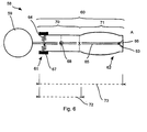
- Fig. 6 1 shows a schematic illustration of a side handle 58.
- the side handle 58 has a fastening means 59 and a grip element 60 with a first end 61 and a second end 62.
- the grip member 60 includes a bearing 63 and a return member 64.
- the attachment means 59 may be, for example, a tension band.
- the handle member 60 is adapted for a user to hold a hand tool 10 thereto.
- the first end 61 of the grip element 60 faces the attachment means 59, the second end 62 of the grip element 60 faces away from the attachment means 59.
- the bearing 63 is disposed in or at the second end 62.
- a connecting element 65 rotatably couples the bearing 63 with the grip element 60 about an axis of rotation 66 that is oriented substantially perpendicular to the connecting element 65.
- the axis of rotation 66 extends through the second end 62, ie through the bearing 63.
- the return element 64 is in or at the first End 61 arranged. The return element 64 exerts a force on the first end 61 when it is deflected relative to the connecting element 65.
- the grip element 60 may have an additional mass 67 at the first end 61. Due to the additional mass 67, a center of gravity 68 of the grip element 60 lies outside a gripping region 69 of the grip element 60 which is intended to be gripped.
- the outer contour of the grip element is subdivided into an inner region 70 and a gripping surface 71.
- the inner region 70 can form the first end 61.
- the length 72 of the inner region 70 may be less than 50 percent, preferably less than 25 percent, of an overall length 73 of the handle member.
- the mass of the additional mass 67 is selected such that the center of gravity 68 lies within the inner region 70.
- the first mass m of the additional mass 67 can be selected as a function of the second mass M of the entire grip element 60.
- a ratio of the first mass m to the second mass M may be at least 0.2 and at most 1.0, e.g. at least 0.5.
Landscapes
- Engineering & Computer Science (AREA)
- Mechanical Engineering (AREA)
- Percussive Tools And Related Accessories (AREA)
Description
- Die vorliegende Erfindung betrifft einen Seitenhandgriff für eine Handwerkzeugmaschine, gemäß der Präambel von Anspruch 1 und wie aus der
GB 2 451 745 A - Ein weiterer Seitenhandgriff ist aus der
EP 1 905 546 A2 bekannt. - Handwerkzeugmaschinen übertragen Vibrationen auf einen Seitenhandgriff. Dämpfende Elemente in dem Seitenhandgriff sollen eine Amplitude der Vibrationen an einer Greiffläche reduzieren.
US 5,157,807 A beschreibt einen solchen Handgriff. - Ein Handgriff gemäß der
GB 2 080 920 A - Der vibrationsgedämpfter Seitenhandgriff ist ein Kompromiss zwischen der Fähigkeit Kräfte des Benutzers auf die Handwerkzeugmaschine übertragen zu können und Vibrationen seitens der Handwerkzeugmaschine auf die Greiffläche zu vermindern. Ein Übertragen von Kräften erfordert steife, unnachgiebige Elemente. Ein Dämpfen, insbesondere niederfrequenter Vibrationen, erfordert weiche, nachgiebige Elemente.
- Alternativ kann die Trägheit des Seitenhandgriffs durch Erhöhen seiner Masse vergrößert werden, um die Dämpfung zu verbessern. Jedoch erhöht sich hierdurch das Gewicht der Handwerkzeugmaschine.
- Eine Aufgabe besteht einen Seitenhandgriff mit einem verbesserten Kompromiss zwischen einer Übertragung von Kräften und einer Minderung von Vibrationen bereitzustellen.
- Diese Aufgabe wird durch den erfindungsgemäßen Seitenhandgriff gemäß den Anspruch 1 gelöst.
- Der erfindungsgemässe Seitenhandgriff für eine Handwerkzeugmaschine beinhaltet ein Griffelement und ein Befestigungsmittel zum Befestigen des Seitenhandgriffs an der Handwerkzeugmaschine. Das Griffelement und das Befestigungsmittel sind zueinander um eine Drehachse verschwenkbar. Die Drehachse verläuft senkrecht zu einer Längsachse des Griffelements und verläuft durch einen von dem Befestigungsmittel abgewandten Endbereich des Griffelements.
- Der Benutzer kann das Griffelement in der Nähe des Endbereichs greifen. Die von ihm ausgeübten, senkrecht zum Griffelement wirkenden Kräfte werden auf das Befestigungsmittel übertragen. Vibrationen, die über das Befestigungsmittel eingeleitet werden, bewirken, dass das Griffelement schwingt. Die Amplitude der Vibrationen wird in eine Schwingungsbewegung übertragen und deren Energie dissipiert und/oder die Amplitude phasenversetzt zu den Vibrationen wieder abgegeben.
- An einem dem Befestigungsmittel zugewandten Endbereich des Griffelements ist ein Rückstellelement zum Rücktreiben des Griffelements in eine Grundstellung bezüglich des Befestigungsmittels vorgesehen. Das Rückstellelement kann auf die Frequenzen der auftretenden Vibrationen abgestimmt sein, damit der Seitenhandgriff als Tilger wirkt. Ein Tilger wird resonant durch die Vibrationen angeregt und gibt die Vibrationen phasenverzögert und damit destruktiv zu neu auftretenden Vibrationen wieder ab.
- Das Griffelement hat ein Lager, das die Drehachse festlegt, um die das Griffelement schwingbar ist, und ein Verbindungselement verbindet das Lager mit dem Befestigungsmittel. Das Verbindungselement kann steif sein. Vorzugsweise ist das Verbindungselement innerhalb der Griffstange angeordnet.
- Das Lager weist wenigstens ein elastisches Element auf, das das Verbindungselement mit dem Griffelement koppelt. Gegenüber einem Gleitlager mit passgenauen Lagerelementen kann das beschriebene Lager einfacher aufgebaut sein. Das elastische Element kann das Verbindungselement ringförmig umschließen.
- Ein Rückstellelement ist an einem dem Befestigungsmittel zugewandten Endbereich des Griffelements vorgesehen, das an dem Verbindungselement und dem Griffelement angreift. Das Rückstellelement kann durch eine Feder gebildet sein. Das Rückstellelement kann durch eine Schraubenfeder oder Spiralfeder gebildet sein, die mit einer ersten Fläche einer ersten Windung an dem Griffelelement und mit einer zweiten Fläche einer zweiten Windung an dem Verbindungselement anliegt. Die zweite Fläche kann von dem Verbindungselement abgewandt sein.
- Eine Ausgestaltung sieht vor, dass an einem dem Befestigungsmittel zugewandten Endbereich des Griffelements eine Zusatzmasse angebracht ist. Die Zusatzmasse erhöht das Drehmoment des schwingenden Griffelements. Aufgrund der Hebelwirkung wird bereits eine große Wirkung bei einer vergleichsweise geringen Masse erreicht.
- Eine Ausgestaltung sieht vor, dass ein Schwerpunkt des Griffelements außerhalb einer vorgegebenen Greiffläche liegt.
- Die nachfolgende Beschreibung erläutert die Erfindung anhand von exemplarischen Ausführungsformen und Figuren. In den Figuren zeigen:
- Fig. 1
- eine Handwerkzeugmaschine,
- Fig. 2
- einen Seitenhandgriff,
- Fig. 3
- einen Seitenhandgriff,
- Fig. 4
- einen Schnitt durch den Seitenhandgriff von
Fig. 3 , - Fig. 5
- eine Detailansicht eines Seitenhandgriffs,
- Fig. 6
- einen schematisch dargestellten Seitenhandgriff.
- Gleiche oder funktionsgleiche Elemente werden durch gleiche Bezugszeichen in den Figuren indiziert, soweit nicht anders angegeben.
-
Fig. 1 zeigt eine Handwerkzeugmaschine 10. Die Handwerkzeugmaschine 10 kann anstelle der beispielhaft dargestellten Schlagbohrmaschine z.B. auch eine Bohrmaschine, ein Meisselhammer, ein Elektroschrauber oder ein Scheibenschleifer sein. Die Handwerkzeugmaschine 10 weist einen Handgriff 11 und nahe einer Werkzeugaufnahme 12 einen zusätzlichen Seitenhandgriff 13 auf. Der Seitenhandgriff 13 ist vorzugsweise lösbar an der Handwerkzeugmaschine 10 anbringbar. Der Seitenhandgriff 13 erleichtert einem Benutzer der Handwerkzeugmaschine 10 durch ein zweihändiges Halten, insbesondere bei schweren Handwerkzeugmaschinen 10, ein Führen der Handwerkzeugmaschine 10. -
Fig. 2 zeigt im Querschnitt eine Ausführungsform des Seitenhandgriffs 13. Der Seitenhandgriff 13 weist ein Spannband 14 auf, mittels dem der Seitenhandgriff 13 an der Handwerkzeugmaschine 10 befestigbar ist. Das Spannband 14 legt eine Orientierung des Seitenhandgriffs 13 entlang einer Achse 15 fest. Die Achse 15 kann beispielsweise bei einem an der Handwerkzeugmaschine 10 befestigten Seitenhandgriff 13 parallel zu einer Schlagrichtung oder Wirkrichtung 16 der Handwerkzeugmaschine 10 sein. Anstelle eines Spannbands 14 kann der Seitenhandgriff 13 auch über eine Schraubverbindung oder ein anderes geeignetes Befestigungsmittel an der Handwerkzeugmaschine 10 befestigt werden. - Der Seitenhandgriff 13 beinhaltet eine Griffstange 17 mit einer Greiffläche 18. Die Greiffläche 18 kann ein Benutzer zumindest teilweise umgreifen. Ein hautverträglicher Kunststoff kann um die Griffstange 17 gespritzt sein, welcher die Greiffläche 18 ausbildet. Die Greiffläche 18 kann entsprechend der anatomischen Form einer Hand ausgebildet sein. Eine Anlage für den greifenden Daumen und Zeigefinger können somit vorgegeben werden.
- Die Griffstange 17 kann hohl als Griffhülse 19 ausgebildet sein. Die Griffstange 17 ist in etwa senkrecht zu der Achse 15. Ein erstes Ende 20 der Griffstange 17 ist dem Spannband 14 zugewandt, ein zweites Ende 21 der Griffstange 17 ist von dem Spannband 14 abgewandt.
- Die Griffstange 17 ist gegenüber dem Spannband 14 verschwenkbar um eine Drehachse 22 gelagert. Die Drehachse 22 verläuft durch das zweite Ende 21 der Griffstange 17 und ist im Wesentlichen parallel zu der Achse 15. In der Griffstange 17 ist beispielsweise ein Lager 23 an dem zweiten Ende 21 eingesetzt. Das Lager 23 weist ein erstes Lagerelement 24 und ein zweites Lagerelement 25 auf, die gegeneinander um wenigstens die Drehachse 22 verdrehbar sind. Das erste Lagerelement 24 ist drehstarr mit der Griffstange 17, z.B. der Griffhülse 19, verbunden. Das zweite Lagerelement 25 ist über eine Verbindungsstange 26 mit dem Spannband 14 verbunden. Die Verbindungsstange 26 kann aus einem steifen Material gefertigt sein. Die Verbindungsstange 26 kann innerhalb der Griffhülse 19 angeordnet sein. Das erste Ende 20 der Griffstange 17 ist von dem Spannband 14 derart beabstandet, dass das erste Ende 20 bezüglich dem Spannband 14 in einer drehenden Bewegung um die Drehachse 22 bewegbar ist. Ein Dichtungselement 27, z.B. ein Filzring oder ein Faltenbalg, kann an dem Spannband 14 vorgesehen sein, das einen Zwischenraum 28 zwischen dem Spannband 14 und dem ersten Ende 20 abdichtet.
- An dem ersten Ende 20 der Griffstange 17 ist eine Feder 29 vorgesehen. Die Feder 29 übt eine Kraft 30 im Wesentlichen längs der Achse 15 von der Verbindungsstange 26 auf die Griffstange 17 aus. Die Feder 29 agiert als Rückstellelement, das nach einem Verschwenken der Griffstange 17 gegenüber der Verbindungsstange 26, die Griffstange 17 wieder in eine Grundstellung zurücktreibt. Die Feder 29 kann Druck- und/oder Zugkräfte ausüben. Vorzugsweise ist die Feder 29 ausgelegt, bei einer parallelen Stellung von Griffstange 17 und Verbindungsstange 26 keine Kraft auszuüben.
- An dem ersten Ende 20 kann ein Massekörper 31 angeordnet werden. Eine Masse des Massekörpers 31 ist derart gewählt, dass der Schwerpunkt 32 der Griffstange 17 außerhalb der Greiffläche 18 liegt. Der Massekörper 31 kann innerhalb einer Abrutschsicherung 33 an dem ersten Ende 20 integriert werden.
- Eine Auslenkung der Griffstange 17 kann durch Stoppelemente 34 beschränkt werden. Das Stoppelement 34 kann beispielsweise durch einen Vorsprung an der Verbindungsstange 26 oder innerhalb der Griffstange 17 gebildet sein. Die Dämpfung kann insbesondere unterbunden werden, wenn der Benutzer die Handwerkzeugmaschine 10 von einem Werkstück wegzieht. Das Stoppelement 34 kann dazu asymmetrisch zur Achse 15 auf einer Seite angeordnet werden, die in Wirkrichtung 16 der Handwerkzeugmaschine 10 weist, wenn der Seitenhandgriff 13 an der Handwerkzeugmaschine 10 befestigt ist. Auf dem Stoppelement 34 oder einer dem Stoppelement 34 gegenüberliegenden Fläche 36 kann ein elastischer Puffer angeordnet sein.
-
Fig. 3 zeigt eine weitere Ausgestaltung eines Seitenhandgriffs 38. Der Aufbau unterscheidet sich von dem in Zusammenhang mitFig. 2 beschrieben Seitenhandgriff 13 unter Anderem in der Ausführung des Lagers 39 und des Rückstellelements 40. Die beiden Ausgestaltungen können miteinander kombiniert werden, z.B. durch Austauschen des Lagers und/oder des Rückstellelements. - Das Lager 39 besteht aus einer ersten Lagerschale 41, einer zweiten Lagerschale 42 und einem Federelement 43. Die erste Lagerschale 41 ist durch ein Endstück 44 der Verbindungsstange 26 ausgebildet. In dem Endstück 44 ist eine Vertiefung 45, z.B. eine ringförmige oder sternförmige Vertiefung 45 eingebracht. Die zweite Lagerschale 42 kann durch eine Innenkontur 46 des zweiten Endes 21 ausgebildet sein. Das Federelement 43 kann durch elastische Elemente gebildet sein, z.B. einen Ring aus elastischem Kunststoff. Das Federelement oder die Federelemente greifen in die gegenüberliegenden Vertiefungen 45, 46 der beiden Lagerschalen 41, 42 ein.
-
Fig. 4 zeigt eine mögliche Ausgestaltung des elastischen Elements 47 und die Lagerschalen 41, 42 im Querschnitt entlang der Ebene A-A ausFig. 3 - Eine von den Ansprüchen nicht umfasste Ausgestaltung sieht vor, das Lager als Festkörpergelenk 48 auszubilden. Das Festkörpergelenk 48 ist als Ausschnitt in
Fig. 5 dargestellt. Die Verbindungsstange 49 ist aus einem elastischen Material gefertigt. An einer Verbundstelle 50 ist das zweite Ende 21 der Griffstange 17 mit der Verbindungsstange 49 form- und/oder kraftschlüssig angelegt, z.B. durch eine Klemm- oder Schraubverbindung. Die Verbindungsstange 49 ist in einem Bereich 51 dünner ausgebildet. Die Querschnittsfläche in dem dünneren Bereich 51 ist derart gewählt, dass sich die Verbindungsstange 49 im Wesentlichen bei den auftretenden Kräften nur in dem dünneren Bereich 51 verbiegt. Der dünnere Bereich 51 liegt im Bereich des zweiten Endes 21 der Griffstange 17. - Das Rückstellelement 40 beinhaltet eine Schraubenfeder 52. Eine Längsachse 53 der Schraubenfeder 52 ist kolinear zu der Verbindungsstange 26. Eine erste Windung 54 der Schraubenfeder 52 berührt mit einer zur Längsachse 53 zeigenden Fläche die Verbindungsstange 26. Eine zweite Windung 55 der Schraubenfeder 52 berührt mit einer von der Längsachse 53 abgewandten Fläche die Griffstange 17. Bei einer Auslenkung der Griffstange 17 gegenüber der Verbindungsstange 26 wird eine Scherkraft auf die Schraubenfeder 52 ausgeübt. Die Schraubenfeder 52 wirkt der Scherkraft durch eine entsprechende Gegenkraft entgegen. Die Schraubenfeder 52 kann durch einen ersten Steg 56 an der Verbindungsstange 26 und einen zweiten Steg 57 in der Griffstange 17 entlang der Längsachse 53 eingespannt sein.
-
Fig. 6 zeigt eine schematische Darstellung eines Seitenhandgriffs 58. Der Seitenhandgriff 58 weist ein Befestigungsmittel 59 und ein Griffelement 60 mit einem ersten Ende 61 und einem zweiten Ende 62 auf. Das Griffelement 60 beinhaltet ein Lager 63 und ein Rückstellelement 64. Das Befestigungsmittel 59 kann beispielsweise ein Spannband sein. Das Griffelement 60 ist geeignet, damit ein Benutzer eine Handwerkzeugmaschine 10 daran festhalten kann. Das erste Ende 61 des Griffelements 60 ist dem Befestigungsmittel 59 zugewandt, das zweite Ende 62 des Griffelements 60 ist von dem Befestigungsmittel 59 abgewandt. Das Lager 63 ist in oder an dem zweiten Ende 62 angeordnet. Ein Verbindungselement 65 koppelt das Lager 63 mit dem Griffelement 60 drehbar um eine Drehachse 66, die im Wesentlichen senkrecht zu dem Verbindungselement 65 orientiert ist. Die Drehachse 66 verläuft durch das zweite Ende 62, d.h. durch das Lager 63. Das Rückstellelement 64 ist in oder an dem ersten Ende 61 angeordnet. Das Rückstellelement 64 übt eine Kraft auf das erste Ende 61 aus, wenn dieses gegenüber dem Verbindungselement 65 ausgelenkt ist. - Das Griffelement 60 kann an dem ersten Ende 61 eine Zusatzmasse 67 aufweisen. Aufgrund der Zusatzmasse 67 liegt ein Schwerpunkt 68 des Griffelements 60 außerhalb einer zum Greifen vorgesehenen Greifbereichs 69 des Griffelements 60. Die Außenkontur des Griffelements unterteilt sich in einen inneren Bereich 70 und eine Greiffläche 71. Der innere Bereich 70 kann das erste Ende 61 bilden. Die Länge 72 des inneren Bereichs 70 kann weniger als 50 Prozent, vorzugsweise weniger als 25 Prozent einer Gesamtlänge 73 des Griffelements betragen. Die Masse der Zusatzmasse 67 ist derart gewählt, dass der Schwerpunkt 68 Innerhalb des inneren Bereichs 70 liegt. Die erste Masse m der Zusatzmasse 67 kann in Abhängigkeit der zweiten Masse M des gesamten Griffelements 60 gewählt werden. Ein Verhältnis der ersten Masse m zu der zweiten Masse M kann wenigstens 0,2 und höchstens 1,0 betragen, z.B. wenigstens 0,5.
Claims (9)
- Seitenhandgriff für eine Handwerkzeugmaschine mit
einem Griffelement (60, 17) und einem Befestigungsmittel (59, 14) zum Befestigen des Seitenhandgriffs an der Handwerkzeugmaschine,
wobei das Griffelement (60, 17) und das Befestigungsmittel (59, 14) zueinander um eine Drehachse (52, 22) verschwenkbar sind, wobei die Drehachse (52, 22) senkrecht zu einer Längsachse des Griffelements (60, 17) und durch einen von dem Befestigungsmittel (59, 14) abgewandten Endbereich (62, 21) des Griffelements (60, 17) verläuft, wobei das Griffelement (60, 17) ein Lager (63, 23, 39) hat, das die Drehachse (52, 22) festlegt, um die das Griffelement (60, 17) schwingbar ist, und wobei ein Verbindungselement (65, 26, 49) das Lager (63, 23, 39) mit dem Befestigungsmittel (59, 14) verbindet,
wobei das Lager (63, 23, 39) wenigstens ein elastisches Element (47) aufweist, das das Verbindungselement (65, 26, 49) mit dem Griffelement (60, 17) koppelt,
dadurch gekennzeichnet, dass zum Rücktreiben des Griffelements (60, 17) in eine Grundstellung bezüglich des Befestigungsmittels (59, 14) an einem dem Befestigungsmittel (59, 14) zugewandten Endbereich (61, 20) des Griffelements (60, 17) ein Rückstellelement (64, 29, 52) vorgesehen ist, das an dem Verbindungselement (65, 26, 49) und dem Griffelement (60, 17) angreift. - Seitenhandgriff nach Anspruch 1, dadurch gekennzeichnet, dass das Rückstellelement (64, 29, 52) durch eine Feder gebildet ist.
- Seitenhandgriff nach Anspruch 2, dadurch gekennzeichnet, dass das Rückstellelement (64, 29, 52) durch eine Schraubenfeder (52) oder Spiralfeder gebildet ist, die mit einer ersten Fläche einer ersten Windung (54) an dem Griffelelement (60, 17) und mit einer zweiten Fläche einer zweiten Windung (55) an dem Verbindungselement (65, 26, 49) anliegt.
- Seitenhandgriff nach Anspruch 3, dadurch gekennzeichnet, dass die zweite Fläche von dem Verbindungselement (65, 26, 49) abgewandt ist.
- Seitenhandgriff nach Anspruch 1, dadurch gekennzeichnet, dass das elastische Element das Verbindungselement (65, 26, 49) ringförmig umschließt.
- Seitenhandgriff nach einem der vorhergehenden Ansprüche, dadurch gekennzeichnet, dass an einem dem Befestigungsmittel (59, 14) zugewandten Endbereich (61, 20) des Griffelements (60, 17) eine Zusatzmasse (67, 31) angebracht ist.
- Seitenhandgriff nach einem der vorhergehenden Ansprüche, dadurch gekennzeichnet, dass eine Masse der Zusatzmasse (67, 31) derart gewählt ist, dass ein Schwerpunkt (68, 32) des Griffelements (60, 17) außerhalb einer vorgegebenen Greiffläche (69, 18) liegt.
- Seitenhandgriff nach Anspruch 7, dadurch gekennzeichnet, dass der Schwerpunkt (68, 32) des Griffelements (60, 17) weniger als ein Viertel einer Gesamtlänge des Griffelements (60, 17) von dem Befestigungsmittel (59, 14) beabstandet ist.
- Handwerkzeugmaschine mit einem Seitenhandgriff nach einem der vorhergehenden Ansprüche.
Applications Claiming Priority (1)
| Application Number | Priority Date | Filing Date | Title |
|---|---|---|---|
| DE102009002463A DE102009002463A1 (de) | 2009-04-17 | 2009-04-17 | Seitenhandgriff |
Publications (2)
| Publication Number | Publication Date |
|---|---|
| EP2241408A1 EP2241408A1 (de) | 2010-10-20 |
| EP2241408B1 true EP2241408B1 (de) | 2012-08-29 |
Family
ID=42111415
Family Applications (1)
| Application Number | Title | Priority Date | Filing Date |
|---|---|---|---|
| EP10157822A Active EP2241408B1 (de) | 2009-04-17 | 2010-03-25 | Seitenhandgriff |
Country Status (3)
| Country | Link |
|---|---|
| US (1) | US9242363B2 (de) |
| EP (1) | EP2241408B1 (de) |
| DE (1) | DE102009002463A1 (de) |
Cited By (1)
| Publication number | Priority date | Publication date | Assignee | Title |
|---|---|---|---|---|
| US11084006B2 (en) | 2017-03-23 | 2021-08-10 | Milwaukee Electric Tool Corporation | Mud mixer |
Families Citing this family (17)
| Publication number | Priority date | Publication date | Assignee | Title |
|---|---|---|---|---|
| JP5128998B2 (ja) * | 2008-04-04 | 2013-01-23 | 株式会社マキタ | 手持式作業工具 |
| DE202010002296U1 (de) * | 2010-02-11 | 2011-08-26 | Illinois Tool Works Inc. | Handgriffanordnung |
| DE102011078376A1 (de) * | 2011-06-30 | 2013-01-03 | Robert Bosch Gmbh | Handgriffvorrichtung, insbesondere für Handwerkzeuge |
| EP2809470B1 (de) | 2012-02-03 | 2020-01-15 | Milwaukee Electric Tool Corporation | Bohrhammer |
| DE102013201620A1 (de) * | 2013-01-31 | 2014-08-14 | Hilti Aktiengesellschaft | Abknickbare Haltevorrichtung |
| EP2969342B1 (de) * | 2013-03-14 | 2021-05-12 | Robert Bosch GmbH | Strombetriebenes handwerkzeug mit schwingungsisolierung |
| JP5997660B2 (ja) * | 2013-05-29 | 2016-09-28 | 株式会社マキタ | 補助ハンドルおよび補助ハンドルを備えた往復動式作業工具 |
| WO2015061370A1 (en) | 2013-10-21 | 2015-04-30 | Milwaukee Electric Tool Corporation | Adapter for power tool devices |
| JP2015139864A (ja) * | 2014-01-30 | 2015-08-03 | パナソニックIpマネジメント株式会社 | 補助ハンドルおよび補助ハンドル付き電動工具 |
| JP2016187854A (ja) * | 2015-03-30 | 2016-11-04 | 日立工機株式会社 | 動力工具 |
| EP3127658A1 (de) * | 2015-08-06 | 2017-02-08 | HILTI Aktiengesellschaft | Seitenhandgriff |
| EP3213879A1 (de) * | 2016-03-03 | 2017-09-06 | HILTI Aktiengesellschaft | Vibrationsmindernder zusatzhandgriff |
| EP3608064B1 (de) * | 2018-08-06 | 2021-06-30 | Hilti Aktiengesellschaft | Handgriff und handwerkzeugmaschine |
| EP3670099A1 (de) | 2018-12-17 | 2020-06-24 | Hilti Aktiengesellschaft | Handgeführtes elektrowerkzeug und seitlicher handgriff |
| US11433524B2 (en) * | 2018-12-19 | 2022-09-06 | George E. Westinghouse | Vibration reducing extension system |
| EP3756833A1 (de) * | 2019-06-26 | 2020-12-30 | Hilti Aktiengesellschaft | Seitenhandgriff für eine elektrische handwerkzeugmaschine |
| WO2022204118A1 (en) * | 2021-03-25 | 2022-09-29 | Milwaukee Electric Tool Corporation | Side handle for power tool |
Family Cites Families (41)
| Publication number | Priority date | Publication date | Assignee | Title |
|---|---|---|---|---|
| US3322211A (en) * | 1964-05-06 | 1967-05-30 | Novosib Elektrotekhnichesky I | Elastic handle for vibrating-impact mechanisms |
| JPS6044530B2 (ja) * | 1980-03-13 | 1985-10-04 | 正治 窪川 | 振動機器の防振緩衝把手 |
| DE8006965U1 (de) * | 1980-03-14 | 1981-08-27 | Robert Bosch Gmbh, 7000 Stuttgart | Zusatzhandgriff fuer eine handwerkzeugmaschine |
| JPS57150014A (en) * | 1980-06-21 | 1982-09-16 | Makoto Minamidate | Oscillation control type handle device |
| JPS5834271B2 (ja) * | 1980-07-18 | 1983-07-26 | 日立工機株式会社 | 振動工具のハンドル防振装置 |
| SE442963B (sv) * | 1984-05-07 | 1986-02-10 | Atlas Copco Ab | Vibrationsisolerande handtag |
| US4819742A (en) * | 1987-06-12 | 1989-04-11 | White Consolidated Industries, Inc. | Vibration-damping control handle for a portable power tool |
| DE3839207A1 (de) * | 1988-11-19 | 1990-05-23 | Hilti Ag | Tragbares handgeraet mit schlagwerk |
| DE4011124A1 (de) | 1990-04-06 | 1991-10-10 | Metabowerke Kg | Vibrationsgedaempfter handgriff |
| US5273120A (en) * | 1993-05-26 | 1993-12-28 | Ingersoll-Rand Company | Power tool with a vibration absorbing handle |
| US5365637A (en) * | 1993-06-15 | 1994-11-22 | Ingersoll-Rand Company | Flex handle for a power tool |
| DE29700003U1 (de) * | 1997-01-02 | 1997-02-27 | Wacker Werke Kg | Aufbruch- und/oder Bohrhammer |
| DE10130088C2 (de) * | 2001-06-21 | 2003-10-16 | Hilti Ag | Schlagendes Elektrohandwerkzeuggerät mit aktiver Vibrationsdämpfung |
| DE10130548B4 (de) * | 2001-06-25 | 2008-01-03 | Robert Bosch Gmbh | Zusatzhandgriff |
| EP1882560B1 (de) * | 2003-09-10 | 2011-06-08 | Makita Corporation | Schwingungsfreier Griff |
| DE10347944B4 (de) * | 2003-10-15 | 2016-11-10 | Robert Bosch Gmbh | Zusatzhandgriff |
| DE102005007547A1 (de) * | 2005-02-18 | 2006-08-31 | Robert Bosch Gmbh | Handwerkzeugmaschine |
| US7252156B2 (en) * | 2005-03-31 | 2007-08-07 | Makita Corporation | Vibration isolation handle |
| DE102005028918A1 (de) * | 2005-06-22 | 2006-12-28 | Wacker Construction Equipment Ag | Bohr- und/oder Schlaghammer mit Leerlaufsteuerung |
| US7676890B2 (en) * | 2005-10-25 | 2010-03-16 | Black And Decker, Inc. | Vibration dampening handle for a powered apparatus |
| DE102005000205A1 (de) * | 2005-12-23 | 2007-06-28 | Hilti Ag | Handgriff eines handgeführten Werkzeuggerätes |
| DE102006016442A1 (de) * | 2006-04-07 | 2007-10-11 | Robert Bosch Gmbh | Handwerkzeugmaschine mit vibrationsgedämpftem Handgriff |
| EP1905546A3 (de) * | 2006-09-27 | 2008-09-03 | Robert Bosch Gmbh | Handgriff |
| DE102007000093A1 (de) * | 2007-02-15 | 2008-08-21 | Hilti Ag | Handwerkzeuggerät |
| DE102007012312A1 (de) * | 2007-03-14 | 2008-09-18 | Robert Bosch Gmbh | Handgriff |
| DE102007055735A1 (de) * | 2007-03-29 | 2008-10-02 | Robert Bosch Gmbh | Handgriff |
| DE102007037046A1 (de) * | 2007-08-06 | 2009-02-12 | Robert Bosch Gmbh | Zusatzhandgriffvorrichtung |
| DE102007037043A1 (de) * | 2007-08-06 | 2009-02-12 | Robert Bosch Gmbh | Zusatzhandgriffvorrichtung |
| DE102007037047A1 (de) * | 2007-08-06 | 2009-02-12 | Robert Bosch Gmbh | Zusatzhandgriffvorrichtung |
| DE102007037048A1 (de) * | 2007-08-06 | 2009-02-12 | Robert Bosch Gmbh | Zusatzhandgriffvorrichtung |
| DE102007047883A1 (de) * | 2007-11-28 | 2009-06-04 | Hilti Aktiengesellschaft | Handwerkzeugmaschine mit Zusatzhandgriff mit Tiefenanschlag |
| DE102008004875A1 (de) * | 2008-01-17 | 2009-07-23 | Robert Bosch Gmbh | Handgriff für ein Elektrohandwerkzeug |
| DE102008000516A1 (de) * | 2008-03-05 | 2009-09-10 | Robert Bosch Gmbh | Zusatzhandgriff sowie Handwerkzeugmaschine |
| JP5128998B2 (ja) * | 2008-04-04 | 2013-01-23 | 株式会社マキタ | 手持式作業工具 |
| US8342705B2 (en) * | 2008-09-02 | 2013-01-01 | Jacobs Chuck Manufacturing Company | Removable work light assembly for a hand tool |
| US20100064860A1 (en) * | 2008-09-18 | 2010-03-18 | Combined Products Co. #1 Inc. | Extension shaft for holding a tool for rotary driven motion |
| US8789447B2 (en) * | 2008-09-18 | 2014-07-29 | Eazypower Corporation | Extension shaft for hold a tool for rotary driven motion |
| JP5277017B2 (ja) * | 2009-02-13 | 2013-08-28 | 株式会社マキタ | 補助ハンドル |
| DE102009046789A1 (de) * | 2009-11-17 | 2011-05-19 | Robert Bosch Gmbh | Handwerkzeugmaschinenvorrichtung |
| DE102013210749A1 (de) * | 2012-11-27 | 2014-05-28 | Robert Bosch Gmbh | System mit einem Zusatzhandgriff und einem Handwerkzeug |
| JP6105454B2 (ja) * | 2013-11-26 | 2017-03-29 | 株式会社マキタ | 作業工具 |
-
2009
- 2009-04-17 DE DE102009002463A patent/DE102009002463A1/de not_active Withdrawn
-
2010
- 2010-03-25 EP EP10157822A patent/EP2241408B1/de active Active
- 2010-04-15 US US12/798,970 patent/US9242363B2/en active Active
Cited By (1)
| Publication number | Priority date | Publication date | Assignee | Title |
|---|---|---|---|---|
| US11084006B2 (en) | 2017-03-23 | 2021-08-10 | Milwaukee Electric Tool Corporation | Mud mixer |
Also Published As
| Publication number | Publication date |
|---|---|
| EP2241408A1 (de) | 2010-10-20 |
| US9242363B2 (en) | 2016-01-26 |
| DE102009002463A1 (de) | 2010-10-21 |
| US20100282484A1 (en) | 2010-11-11 |
Similar Documents
| Publication | Publication Date | Title |
|---|---|---|
| EP2241408B1 (de) | Seitenhandgriff | |
| EP2072191B1 (de) | Handwerkzeugmaschine | |
| EP1958735B1 (de) | Handwerkzeuggerät | |
| EP2247413B1 (de) | Schwingungsentkoppelter handgriff | |
| EP1800804B1 (de) | Handwerkzeuggerät mit gefederter Griffaufhängung | |
| DE102010040173A1 (de) | Handwerkzeugmaschine | |
| DE4011124A1 (de) | Vibrationsgedaempfter handgriff | |
| WO2002083369A1 (de) | Handwerkzeugmaschine mit vibrationsgedämpftem handgriff | |
| DE102007000057B4 (de) | Schwingungstilger für Handwerkzeugmaschine | |
| EP2216141A1 (de) | Handwerkzeugmaschine mit vibrationsgedämpftem Handgriff | |
| WO2008034668A1 (de) | Elektrowerkzeugmaschine mit schwingungsentkoppeltem griffelement | |
| EP2841237B1 (de) | Handführbare werkzeugmaschine mit gehäuse | |
| DE202010002296U1 (de) | Handgriffanordnung | |
| DE112014001999T5 (de) | Handgriffvorrichtung und angetriebenes Werkzeug mit derselben Handgriffvorrichtung | |
| DE102009046348A1 (de) | Dämpfungsvorrichtung, Werkzeugmaschine mit einer Dämpfungsvorrichtung und Verfahren zur Herstellung einer Dämpfungsvorrichtung | |
| EP2191941B1 (de) | Zusatzhandgriff für eine Handwerkzeugmaschine | |
| EP3331665A1 (de) | Seitenhandgriff | |
| WO2021008877A1 (de) | Handwerkzeugmaschine | |
| EP1674210B1 (de) | Werkzeuggerät mit entkoppeltem Haupthandgriff | |
| EP2452782B1 (de) | Handwerkzeugmaschine | |
| WO2009106165A1 (de) | Handgriff für elektrohandwerkzeug | |
| DE202017101409U1 (de) | Hilfsgriff und Arbeitswerkzeug | |
| DE102009029626B4 (de) | Handwerkzeugmaschine | |
| EP2822734A1 (de) | Handwerkzeugmaschinenvorrichtung | |
| WO2009074410A1 (de) | Handgriff |
Legal Events
| Date | Code | Title | Description |
|---|---|---|---|
| PUAI | Public reference made under article 153(3) epc to a published international application that has entered the european phase |
Free format text: ORIGINAL CODE: 0009012 |
|
| AK | Designated contracting states |
Kind code of ref document: A1 Designated state(s): AT BE BG CH CY CZ DE DK EE ES FI FR GB GR HR HU IE IS IT LI LT LU LV MC MK MT NL NO PL PT RO SE SI SK SM TR |
|
| AX | Request for extension of the european patent |
Extension state: AL BA ME RS |
|
| 17P | Request for examination filed |
Effective date: 20110420 |
|
| 17Q | First examination report despatched |
Effective date: 20111130 |
|
| REG | Reference to a national code |
Ref country code: DE Ref legal event code: R079 Ref document number: 502010001185 Country of ref document: DE Free format text: PREVIOUS MAIN CLASS: B25D0017040000 Ipc: B25F0005020000 |
|
| GRAP | Despatch of communication of intention to grant a patent |
Free format text: ORIGINAL CODE: EPIDOSNIGR1 |
|
| RIC1 | Information provided on ipc code assigned before grant |
Ipc: B25D 17/04 20060101ALI20120425BHEP Ipc: B25F 5/02 20060101AFI20120425BHEP Ipc: B25F 5/00 20060101ALI20120425BHEP |
|
| GRAS | Grant fee paid |
Free format text: ORIGINAL CODE: EPIDOSNIGR3 |
|
| GRAA | (expected) grant |
Free format text: ORIGINAL CODE: 0009210 |
|
| AK | Designated contracting states |
Kind code of ref document: B1 Designated state(s): AT BE BG CH CY CZ DE DK EE ES FI FR GB GR HR HU IE IS IT LI LT LU LV MC MK MT NL NO PL PT RO SE SI SK SM TR |
|
| REG | Reference to a national code |
Ref country code: GB Ref legal event code: FG4D Free format text: NOT ENGLISH |
|
| REG | Reference to a national code |
Ref country code: CH Ref legal event code: EP |
|
| REG | Reference to a national code |
Ref country code: AT Ref legal event code: REF Ref document number: 572806 Country of ref document: AT Kind code of ref document: T Effective date: 20120915 |
|
| REG | Reference to a national code |
Ref country code: IE Ref legal event code: FG4D Free format text: LANGUAGE OF EP DOCUMENT: GERMAN |
|
| REG | Reference to a national code |
Ref country code: DE Ref legal event code: R096 Ref document number: 502010001185 Country of ref document: DE Effective date: 20121025 |
|
| REG | Reference to a national code |
Ref country code: SE Ref legal event code: TRGR |
|
| REG | Reference to a national code |
Ref country code: NL Ref legal event code: VDEP Effective date: 20120829 |
|
| REG | Reference to a national code |
Ref country code: LT Ref legal event code: MG4D Effective date: 20120808 |
|
| PG25 | Lapsed in a contracting state [announced via postgrant information from national office to epo] |
Ref country code: HR Free format text: LAPSE BECAUSE OF FAILURE TO SUBMIT A TRANSLATION OF THE DESCRIPTION OR TO PAY THE FEE WITHIN THE PRESCRIBED TIME-LIMIT Effective date: 20120829 Ref country code: IS Free format text: LAPSE BECAUSE OF FAILURE TO SUBMIT A TRANSLATION OF THE DESCRIPTION OR TO PAY THE FEE WITHIN THE PRESCRIBED TIME-LIMIT Effective date: 20121229 Ref country code: FI Free format text: LAPSE BECAUSE OF FAILURE TO SUBMIT A TRANSLATION OF THE DESCRIPTION OR TO PAY THE FEE WITHIN THE PRESCRIBED TIME-LIMIT Effective date: 20120829 Ref country code: NO Free format text: LAPSE BECAUSE OF FAILURE TO SUBMIT A TRANSLATION OF THE DESCRIPTION OR TO PAY THE FEE WITHIN THE PRESCRIBED TIME-LIMIT Effective date: 20121129 Ref country code: CY Free format text: LAPSE BECAUSE OF FAILURE TO SUBMIT A TRANSLATION OF THE DESCRIPTION OR TO PAY THE FEE WITHIN THE PRESCRIBED TIME-LIMIT Effective date: 20120829 Ref country code: LT Free format text: LAPSE BECAUSE OF FAILURE TO SUBMIT A TRANSLATION OF THE DESCRIPTION OR TO PAY THE FEE WITHIN THE PRESCRIBED TIME-LIMIT Effective date: 20120829 |
|
| PG25 | Lapsed in a contracting state [announced via postgrant information from national office to epo] |
Ref country code: GR Free format text: LAPSE BECAUSE OF FAILURE TO SUBMIT A TRANSLATION OF THE DESCRIPTION OR TO PAY THE FEE WITHIN THE PRESCRIBED TIME-LIMIT Effective date: 20121130 Ref country code: SI Free format text: LAPSE BECAUSE OF FAILURE TO SUBMIT A TRANSLATION OF THE DESCRIPTION OR TO PAY THE FEE WITHIN THE PRESCRIBED TIME-LIMIT Effective date: 20120829 Ref country code: LV Free format text: LAPSE BECAUSE OF FAILURE TO SUBMIT A TRANSLATION OF THE DESCRIPTION OR TO PAY THE FEE WITHIN THE PRESCRIBED TIME-LIMIT Effective date: 20120829 Ref country code: PT Free format text: LAPSE BECAUSE OF FAILURE TO SUBMIT A TRANSLATION OF THE DESCRIPTION OR TO PAY THE FEE WITHIN THE PRESCRIBED TIME-LIMIT Effective date: 20121231 |
|
| PG25 | Lapsed in a contracting state [announced via postgrant information from national office to epo] |
Ref country code: ES Free format text: LAPSE BECAUSE OF FAILURE TO SUBMIT A TRANSLATION OF THE DESCRIPTION OR TO PAY THE FEE WITHIN THE PRESCRIBED TIME-LIMIT Effective date: 20121210 Ref country code: CZ Free format text: LAPSE BECAUSE OF FAILURE TO SUBMIT A TRANSLATION OF THE DESCRIPTION OR TO PAY THE FEE WITHIN THE PRESCRIBED TIME-LIMIT Effective date: 20120829 Ref country code: NL Free format text: LAPSE BECAUSE OF FAILURE TO SUBMIT A TRANSLATION OF THE DESCRIPTION OR TO PAY THE FEE WITHIN THE PRESCRIBED TIME-LIMIT Effective date: 20120829 Ref country code: EE Free format text: LAPSE BECAUSE OF FAILURE TO SUBMIT A TRANSLATION OF THE DESCRIPTION OR TO PAY THE FEE WITHIN THE PRESCRIBED TIME-LIMIT Effective date: 20120829 Ref country code: DK Free format text: LAPSE BECAUSE OF FAILURE TO SUBMIT A TRANSLATION OF THE DESCRIPTION OR TO PAY THE FEE WITHIN THE PRESCRIBED TIME-LIMIT Effective date: 20120829 Ref country code: RO Free format text: LAPSE BECAUSE OF FAILURE TO SUBMIT A TRANSLATION OF THE DESCRIPTION OR TO PAY THE FEE WITHIN THE PRESCRIBED TIME-LIMIT Effective date: 20120829 |
|
| PG25 | Lapsed in a contracting state [announced via postgrant information from national office to epo] |
Ref country code: SK Free format text: LAPSE BECAUSE OF FAILURE TO SUBMIT A TRANSLATION OF THE DESCRIPTION OR TO PAY THE FEE WITHIN THE PRESCRIBED TIME-LIMIT Effective date: 20120829 Ref country code: PL Free format text: LAPSE BECAUSE OF FAILURE TO SUBMIT A TRANSLATION OF THE DESCRIPTION OR TO PAY THE FEE WITHIN THE PRESCRIBED TIME-LIMIT Effective date: 20120829 |
|
| PLBE | No opposition filed within time limit |
Free format text: ORIGINAL CODE: 0009261 |
|
| STAA | Information on the status of an ep patent application or granted ep patent |
Free format text: STATUS: NO OPPOSITION FILED WITHIN TIME LIMIT |
|
| PG25 | Lapsed in a contracting state [announced via postgrant information from national office to epo] |
Ref country code: BG Free format text: LAPSE BECAUSE OF FAILURE TO SUBMIT A TRANSLATION OF THE DESCRIPTION OR TO PAY THE FEE WITHIN THE PRESCRIBED TIME-LIMIT Effective date: 20121129 |
|
| 26N | No opposition filed |
Effective date: 20130530 |
|
| REG | Reference to a national code |
Ref country code: DE Ref legal event code: R097 Ref document number: 502010001185 Country of ref document: DE Effective date: 20130530 |
|
| BERE | Be: lapsed |
Owner name: HILTI AKTIENGESELLSCHAFT Effective date: 20130331 |
|
| PG25 | Lapsed in a contracting state [announced via postgrant information from national office to epo] |
Ref country code: MC Free format text: LAPSE BECAUSE OF NON-PAYMENT OF DUE FEES Effective date: 20130331 |
|
| REG | Reference to a national code |
Ref country code: IE Ref legal event code: MM4A |
|
| PG25 | Lapsed in a contracting state [announced via postgrant information from national office to epo] |
Ref country code: IE Free format text: LAPSE BECAUSE OF NON-PAYMENT OF DUE FEES Effective date: 20130325 Ref country code: BE Free format text: LAPSE BECAUSE OF NON-PAYMENT OF DUE FEES Effective date: 20130331 |
|
| PG25 | Lapsed in a contracting state [announced via postgrant information from national office to epo] |
Ref country code: MT Free format text: LAPSE BECAUSE OF FAILURE TO SUBMIT A TRANSLATION OF THE DESCRIPTION OR TO PAY THE FEE WITHIN THE PRESCRIBED TIME-LIMIT Effective date: 20120829 |
|
| REG | Reference to a national code |
Ref country code: CH Ref legal event code: PL |
|
| PG25 | Lapsed in a contracting state [announced via postgrant information from national office to epo] |
Ref country code: CH Free format text: LAPSE BECAUSE OF NON-PAYMENT OF DUE FEES Effective date: 20140331 Ref country code: LI Free format text: LAPSE BECAUSE OF NON-PAYMENT OF DUE FEES Effective date: 20140331 |
|
| PG25 | Lapsed in a contracting state [announced via postgrant information from national office to epo] |
Ref country code: SM Free format text: LAPSE BECAUSE OF FAILURE TO SUBMIT A TRANSLATION OF THE DESCRIPTION OR TO PAY THE FEE WITHIN THE PRESCRIBED TIME-LIMIT Effective date: 20120829 |
|
| PG25 | Lapsed in a contracting state [announced via postgrant information from national office to epo] |
Ref country code: TR Free format text: LAPSE BECAUSE OF FAILURE TO SUBMIT A TRANSLATION OF THE DESCRIPTION OR TO PAY THE FEE WITHIN THE PRESCRIBED TIME-LIMIT Effective date: 20120829 |
|
| PG25 | Lapsed in a contracting state [announced via postgrant information from national office to epo] |
Ref country code: MK Free format text: LAPSE BECAUSE OF FAILURE TO SUBMIT A TRANSLATION OF THE DESCRIPTION OR TO PAY THE FEE WITHIN THE PRESCRIBED TIME-LIMIT Effective date: 20120829 Ref country code: HU Free format text: LAPSE BECAUSE OF FAILURE TO SUBMIT A TRANSLATION OF THE DESCRIPTION OR TO PAY THE FEE WITHIN THE PRESCRIBED TIME-LIMIT; INVALID AB INITIO Effective date: 20100325 Ref country code: LU Free format text: LAPSE BECAUSE OF NON-PAYMENT OF DUE FEES Effective date: 20130325 |
|
| REG | Reference to a national code |
Ref country code: FR Ref legal event code: PLFP Year of fee payment: 7 |
|
| REG | Reference to a national code |
Ref country code: AT Ref legal event code: MM01 Ref document number: 572806 Country of ref document: AT Kind code of ref document: T Effective date: 20150325 |
|
| PG25 | Lapsed in a contracting state [announced via postgrant information from national office to epo] |
Ref country code: AT Free format text: LAPSE BECAUSE OF NON-PAYMENT OF DUE FEES Effective date: 20150325 |
|
| REG | Reference to a national code |
Ref country code: FR Ref legal event code: PLFP Year of fee payment: 8 |
|
| REG | Reference to a national code |
Ref country code: FR Ref legal event code: PLFP Year of fee payment: 9 |
|
| PGFP | Annual fee paid to national office [announced via postgrant information from national office to epo] |
Ref country code: FR Payment date: 20230322 Year of fee payment: 14 |
|
| PGFP | Annual fee paid to national office [announced via postgrant information from national office to epo] |
Ref country code: SE Payment date: 20230314 Year of fee payment: 14 |
|
| PGFP | Annual fee paid to national office [announced via postgrant information from national office to epo] |
Ref country code: IT Payment date: 20230328 Year of fee payment: 14 |
|
| P01 | Opt-out of the competence of the unified patent court (upc) registered |
Effective date: 20230830 |
|
| PGFP | Annual fee paid to national office [announced via postgrant information from national office to epo] |
Ref country code: DE Payment date: 20240320 Year of fee payment: 15 Ref country code: GB Payment date: 20240320 Year of fee payment: 15 |