EP2236673A2 - Flächenrütteleinrichtung - Google Patents
Flächenrütteleinrichtung Download PDFInfo
- Publication number
- EP2236673A2 EP2236673A2 EP10003249A EP10003249A EP2236673A2 EP 2236673 A2 EP2236673 A2 EP 2236673A2 EP 10003249 A EP10003249 A EP 10003249A EP 10003249 A EP10003249 A EP 10003249A EP 2236673 A2 EP2236673 A2 EP 2236673A2
- Authority
- EP
- European Patent Office
- Prior art keywords
- vibrating
- recesses
- plate
- vibrating device
- paving stones
- Prior art date
- Legal status (The legal status is an assumption and is not a legal conclusion. Google has not performed a legal analysis and makes no representation as to the accuracy of the status listed.)
- Granted
Links
Images

Classifications
-
- E—FIXED CONSTRUCTIONS
- E01—CONSTRUCTION OF ROADS, RAILWAYS, OR BRIDGES
- E01C—CONSTRUCTION OF, OR SURFACES FOR, ROADS, SPORTS GROUNDS, OR THE LIKE; MACHINES OR AUXILIARY TOOLS FOR CONSTRUCTION OR REPAIR
- E01C19/00—Machines, tools or auxiliary devices for preparing or distributing paving materials, for working the placed materials, or for forming, consolidating, or finishing the paving
- E01C19/22—Machines, tools or auxiliary devices for preparing or distributing paving materials, for working the placed materials, or for forming, consolidating, or finishing the paving for consolidating or finishing laid-down unset materials
- E01C19/30—Tamping or vibrating apparatus other than rollers ; Devices for ramming individual paving elements
- E01C19/34—Power-driven rammers or tampers, e.g. air-hammer impacted shoes for ramming stone-sett paving; Hand-actuated ramming or tamping machines, e.g. tampers with manually hoisted dropping weight
- E01C19/38—Power-driven rammers or tampers, e.g. air-hammer impacted shoes for ramming stone-sett paving; Hand-actuated ramming or tamping machines, e.g. tampers with manually hoisted dropping weight with means specifically for generating vibrations, e.g. vibrating plate compactors, immersion vibrators
-
- E—FIXED CONSTRUCTIONS
- E01—CONSTRUCTION OF ROADS, RAILWAYS, OR BRIDGES
- E01C—CONSTRUCTION OF, OR SURFACES FOR, ROADS, SPORTS GROUNDS, OR THE LIKE; MACHINES OR AUXILIARY TOOLS FOR CONSTRUCTION OR REPAIR
- E01C23/00—Auxiliary devices or arrangements for constructing, repairing, reconditioning, or taking-up road or like surfaces
- E01C23/06—Devices or arrangements for working the finished surface; Devices for repairing or reconditioning the surface of damaged paving; Recycling in place or on the road
- E01C23/09—Devices or arrangements for working the finished surface; Devices for repairing or reconditioning the surface of damaged paving; Recycling in place or on the road for forming cuts, grooves, or recesses, e.g. for making joints or channels for markings, for cutting-out sections to be removed; for cleaning, treating, or filling cuts, grooves, recesses, or fissures; for trimming paving edges
- E01C23/0966—Devices or arrangements for working the finished surface; Devices for repairing or reconditioning the surface of damaged paving; Recycling in place or on the road for forming cuts, grooves, or recesses, e.g. for making joints or channels for markings, for cutting-out sections to be removed; for cleaning, treating, or filling cuts, grooves, recesses, or fissures; for trimming paving edges for filling or priming, with or without working the surface of the filling or applying particulate material thereto, e.g. for filling the joints of stone-sett paving
Definitions
- the present invention relates to a surface vibrator according to the preamble of claim 1.
- sand In connection with the production of paving, which consists for example of composite stones laid with the help of laying tongs on a sand or gravel bed, sand must be introduced into the joints existing between the individual paving stones. Thereafter, the stones are compacted from above with a so-called surface vibrator.
- the object of the present invention is to avoid these described time-consuming and costly work operations in the production of paving.
- the surface vibrating device comprises a vibration plate displaceable by a drive vibrating plate, which is movable over the surface of laid paving stones.
- a vibrating plate is provided which has recesses opening to the surface of the paving stones, from which sand continuously falls into the gaps existing between the paving stones as the vibrating plate reciprocates over the paving stones.
- the essential advantage of the present invention is that time-consuming and therefore cost-intensive operations, which are normally required in the manufacture of a paving for the introduction of sand into the joints between the individual paving stones of the paving, can be saved because the surface vibrating device according to the invention is designed in this way in that the joints between the paving stones of the paving during actual shaking automatically in the required manner to be filled up with sand.
- the vibrating plate is particularly advantageously formed by the vibrating plate, in which the recesses are arranged.
- the recesses in this case sand located on the surface of the paving stones is continuously absorbable and from the recesses sand is absorbed in the recesses between the recesses in the back and forth on the paving stones continuously received in the recesses in the existing between the paving stones joints.
- the recesses may also have the shape of the vibration plate passing through openings.
- a reservoir space can advantageously be arranged above the vibrating plate, from which sand can be continuously discharged via the passage openings into the joints.
- the paving stones facing side of the reservoir space can be particularly easily formed by the vibration plate.
- the vibrating plate has the form of an attachable to the vibrating plate of the surface vibrating device additional vibrating plate which vibrates together with the vibrating plate and in which the recesses are arranged.
- additional vibration plate can be used in conjunction with existing vibrators as an additional device.
- sand is continuously receivable in the recesses of the additional vibrating plate on the surface of the paving stones sand is continuously receivable. The sand falls out of the recesses in the back and forth Moving the surface vibrating device over the paving stones continuously in the existing between the paving stones joints.
- the recesses may be trough-shaped or have the shape of the vibration plate passing through openings.
- the vibration plate formed by the vibrating plate is made of steel.
- the additional vibration plate may advantageously consist of steel or plastic.
- the vibrating plate can be set in vibration by at least one imbalance or eccentric weight that can be driven by a drive.
- the drive may have the form of an internal combustion engine.
- the recesses or the through holes of the vibrating plate or the recesses or through holes of the additional vibrating plate may be arranged in any patterns in the vibrating plate or the additional vibrating plate.
- Below the vibration plate can be arranged an existing plastic additional vibration plate whose passage openings are aligned with the through holes of the vibrating plate.
- the surface vibrating device is preferably designed such that in the pavement facing surface of a vibrating vibration plate for paving opening recesses or recesses are arranged in which sand provided on the pavement is taken when moving the surface vibrating device during the actual shaking and from which this absorbed sand is introduced and compacted during the shaking process in the joints of the pavement.
- the joints are filled up to the upper edge with sand.
- the recesses thus each serve as a sand reservoir. But it is also conceivable to introduce sand from a special, above the vibrating plate arranged reservoir space through openings of the vibrating plate in the joints, in which case the surface vibrating device does not have to be performed on existing on the surface of the paving stones sand.
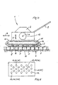
- FIG. 1 a first embodiment of a ceremoninrüttel boots invention 1 is shown schematically.
- This essentially comprises an on the laid on a sand or grit bed 6 paving stones 5 resting vibrating plate, which is preferably in a conventional manner by an eccentric weight 13 which is rotatable about an axis 4, vibrated by the arrow. 7 are indicated.
- a drive 2 is provided to drive the eccentric weight 13.
- the entire surface vibrating device 1 is usually reciprocated with the aid of an operator gripped handle 8 in the direction of the arrow 9 over the pavement. It is known to utilize the rotation of the eccentric weights to produce the forces required to move the surface vibrating device. The direction of movement can be adjusted by adjusting the imbalance of the eccentric weights.
- recesses 10 are provided, which open to the side of the paving stones 5 out. These recesses 10 fill when moving the surface vibrating device 1 on the paving stones 5 arranged on the surface of the paving stones 5 sand that falls when moving back and forth of the surface vibrating device 1 on the surface of the paving stones 5 in the joints between the paving stones 5 and this finally fills up to the top.
- FIGS. 2 and 3 shows a further embodiment of the invention, in which the vibrating plate 14 of the surface vibrating device 1 has no recesses 10, as is conventional in itself. Instead, it's your own, extra Vibration plate 11 is provided, which is attached to the vibrating plate 14 of the surface vibrating device 1 with fastening devices not shown.
- the additional vibrating plate 11 also has recesses or recesses 12, which fulfill the function of the recesses 10 of the vibrating plate 3 during operation of the surface vibrating device 1, because the vibrating plate 14 and the vibrating plate 11 are vibrated together.
- the vibration plate 3 formed by the vibrating plate of the embodiment of the FIG. 1 consists of steel
- the additional vibration plate 11 of the embodiment of the FIGS. 2 and 3 preferably made of a plastic material.
- the recesses 12 may have the shape of recesses or depressions opening toward the side of the paving stones 5. However, it is also conceivable to design the recesses 12 in the manner shown as passage openings.
- FIG. 4 a further embodiment of the invention communiquénrüttel raised explained in more detail. Details of FIG. 4 already related to the FIG. 1 are explained in the appropriate way.
- a reservoir space 15 arranged, which may contain sand in the apparent manner. This sand falls when moving the surface vibrating device 1 via a pavement through the through holes 16 of the vibrating plate 3 in the joints between the paving stones 5.
- a schematically illustrated filling opening 17 may be provided for introducing the sand into the reservoir space 15. If necessary, to protect the paving stones 5 under the vibrating plate 11 according to FIG. 2 be fastened, such that the passage openings 10 and 16 are aligned with each other.
- FIG. 5 show that the recesses 10 provided in the vibration plate 3 (FIG. FIG. 1 ) or through openings 16 (FIG. FIG. 4 ) or the existing in the additional vibration plate 11 recesses 12 ( FIG. 3 ) in contrast to FIG. 3 , in which recesses 12 are provided in rows running side by side, can also be arranged in any other patterns.
Landscapes
- Engineering & Computer Science (AREA)
- Architecture (AREA)
- Civil Engineering (AREA)
- Structural Engineering (AREA)
- Mining & Mineral Resources (AREA)
- Road Paving Machines (AREA)
- Road Paving Structures (AREA)
Abstract
Description
- Die vorliegende Erfindung betrifft eine Flächenrütteleinrichtung nach dem Oberbegriff des Patentanspruches 1.
- Im Zusammenhang mit der Herstellung von Pflasterungen, die beispielsweise aus mit der Hilfe einer Verlegezange auf einem Sand- oder Splittbett verlegten Verbundsteinen bestehen, muss Sand in die zwischen den einzelnen Pflastersteinen bestehenden Fugen eingebracht werden. Danach werden die Steine von oben her mit einem sogenannten Flächenrüttler verdichtet.
- Das Einbringen von Sand in die Fugen erfolgt üblicherweise dadurch, dass auf der Oberfläche der verlegten Steine Sand verteilt und mit einem Handbesen, der von einem Arbeiter hin- und herbewegt wird, in die Fugen eingebracht wird. Es ist erkennbar, dass eine derartige Vorgehensweise äußerst zeitaufwändig und daher kostenintensiv ist. Ein Problem besteht insbesondere auch darin, dass nach dem manuellen Einfegen des Fugensandes und der Bearbeitung der Oberflächen der Steine mit einem Flächenrüttler jeder einzelne Stein, der mit der Rüttelplatte des Flächenrüttlers in Berührung gelangt, in eine Vibrationsbewegung versetzt wird. Dabei setzt sich der zuvor manuell eingefegte Sand in den Fugen zwischen den gerade in Vibrationen versetzten Steinen, so dass diese Fugen nicht mehr vollständig mit Sand aufgefüllt sind. Für die Funktionalität der hergestellten Pflasterung ist es jedoch von ausschlaggebender Bedeutung, dass die einzelnen Fugen zwischen den Pflastersteinen vollständig mit Sand gefüllt sind. Dies wird auch in den einschlägigen Normen gefordert, die für die Herstellung von Pflasterungen maßgeblich sind.
- Um diesen Normen zu entsprechen, muss daher in weiteren Schritten weiterer Sand in die Fugen der durch einen Flächenrüttler bearbeiteten Steine der Pflasterung manuell eingebracht werden. Dies setzt aber weitere zeitaufwändige und kostenintensive Arbeitsoperationen voraus.
- Die Aufgabe der vorliegenden Erfindung besteht darin, diese geschilderten zeitaufwändigen und kostenintensiven Arbeitsoperationen bei der Herstellung von Pflasterungen zu vermeiden.
- Diese Aufgabe wird durch eine Flächenrütteleinrichtung mit den Merkmalen des Patentanspruches 1 gelöst. Demgemäß umfasst die Flächenrütteleinrichtung eine durch einen Antrieb in Schwingungen versetzbare Rüttelplatte, die über die Oberfläche von verlegten Pflastersteinen bewegbar ist. Es ist eine Vibrationsplatte vorgesehen, die sich zur Oberfläche der Pflastersteine hin öffnende Aussparungen aufweist, aus denen beim Hin- und Herbewegen der Vibrationsplatte über die Pflastersteine fortlaufend Sand in die zwischen den Pflastersteinen vorhandenen Fugen fällt.
- Der wesentliche Vorteil der vorliegenden Erfindung besteht darin, dass zeitaufwändige und daher kostenintensive Arbeitsschritte, die normalerweise bei der Herstellung einer Pflasterung zum Einbringen von Sand in die Fugen zwischen den einzelnen Pflastersteinen der Pflasterung erforderlich sind, eingespart werden können, weil die erfindungsgemäße Flächenrütteleinrichtung so ausgestaltet ist, dass die Fugen zwischen den Pflastersteinen der Pflasterung beim eigentlichen Rüttelvorgang automatisch in der geforderten Weise bis oben mit Sand gefüllt werden.
- Vorteilhafte Ausgestaltungen der Erfindung gehen aus den Unteransprüchen hervor. Besonders vorteilhaft wird bei der erfindungsgemäßen Flächenrütteleinrichtung die Vibrationsplatte durch die Rüttelplatte gebildet, in der die Aussparungen angeordnet sind. In die Aussparungen ist dabei auf der Oberfläche der Pflastersteine befindlicher Sand fortlaufend aufnehmbar und aus den Aussparungen ist beim Hin- und Herbewegen der Vibrationsplatte über die Pflastersteine fortlaufend in die Aussparungen aufgenommener Sand in die zwischen den Pflastersteinen vorhandenen Fugen abgebbar. Besonders vorteilhaft ist es, die Aussparungen muldenförmig auszubilden. Die Aussparungen können jedoch auch die Form von die Vibrationsplatte durchsetzenden Durchgangsöffnungen aufweisen. In diesem Fall kann vorteilhafterweise oberhalb der Vibrationsplatte ein Reservoirraum angeordnet sein, aus dem fortlaufend Sand über die Durchgangsöffnungen in die Fugen abgebbar ist. Die den Pflastersteinen zugewandte Seite des Reservoirraumes kann besonders einfach durch die Vibrationsplatte gebildet sein.
- Bei einer Ausgestaltung der erfindungsgemäßen Flächenrütteleinrichtung weist die Vibrationsplatte die Form einer an der Rüttelplatte der Flächenrütteleinrichtung befestigbaren zusätzlichen Vibrationsplatte auf, die zusammen mit der Rüttelplatte schwingt und in der die Aussparungen angeordnet sind. Eine solche zusätzliche Vibrationsplatte kann im Zusammenhang mit bereits bestehenden Rüttlern als Zusatzeinrichtung angewendet werden. Dabei ist in die Aussparungen der zusätzlichen Vibrationsplatte auf der Oberfläche der Pflastersteine befindlicher Sand fortlaufend aufnehmbar. Der Sand fällt aus den Aussparungen beim Hin- und Herbewegen der Flächenrütteleinrichtung über die Pflastersteine fortlaufend in die zwischen den Pflastersteinen vorhandenen Fugen. Die Aussparungen können muldenförmig ausgebildet sein oder die Form von die Vibrationsplatte durchsetzenden Durchgangsöffnungen aufweisen.
- Vorzugsweise besteht bei einer bevorzugten Flächenrütteleinrichtung die durch die Rüttelplatte gebildete Vibrationsplatte aus Stahl.
- Die zusätzliche Vibrationsplatte kann vorteilhaft aus Stahl oder Kunststoff bestehen. Die Rüttelplatte kann durch wenigstens ein durch einen Antrieb antreibbares Unwucht- oder Exzentergewicht in Schwingungen versetzt werden. Der Antrieb kann die Form einer Brennkraftmaschine aufweisen. Die Aussparungen oder die Durchgangsöffnungen der Vibrationsplatte oder die Aussparungen oder Durchgangsöffnungen der zusätzlichen Vibrationsplatte können in beliebigen Mustern in der Vibrationsplatte oder der zusätzlichen Vibrationsplatte angeordnet sein. Unterhalb der Vibrationsplatte kann eine aus Kunststoff bestehende zusätzliche Vibrationsplatte angeordnet sein, deren Durchgangsöffnungen zu den Durchgangsöffnungen der Vibrationsplatte ausgerichtet sind.
- Durch eine Vibrationsplatte aus Kunststoff kann eine besondere Schonung des Pflasters erreicht werden.
- Im folgenden werden die Erfindungen und deren Ausgestaltungen im Zusammenhang mit den Figuren näher erläutert. Es zeigen:
-
Figur 1 die Seitenansicht einer ersten Ausführungsform einer erfindungsgemäßen Flächenrütteleinrichtung, -
Figur 2 eine zweite Ausführungsform der erfindungsgemäßen Flächenrütteleinrichtung, wobei eine als Zusatzteil verwendbare Vibrationsplatte vorgesehen ist, -
Figur 3 eine Ansicht von oben auf die Vibrationsplatte derFigur 2 , -
Figur 4 eine dritte Ausführungsform der erfindungsgemäßen Flächenrütteleinrichtung und -
Figur 5 eine Weiterbildung der Erfindung. - Zu der Erfindung führten die folgenden Überlegungen.
- Um in die zwischen den einzelnen, auf einem Splitt- oder Sandbett verlegten Pflastersteinen einer Pflasterung bestehenden Fugen bis zur Oberkante der Fugen Sand beim eigentlichen Abrütteln der Pflastersteine mit einer Flächenrütteleinrichtung einbringen zu können, ist es denkbar, die Flächenrütteleinrichtung über auf der Oberfläche der Pflasterung liegenden Sand zu führen. Dabei ist die Flächenrütteleinrichtung vorzugsweise so ausgestaltet ist, dass in der der Pflasterung zugewandten Oberfläche einer in Vibrationen versetzten Vibrationsplatte sich zur Pflasterung hin öffnende Aussparungen bzw. Ausnehmungen angeordnet sind, in denen auf der Pflasterung vorgesehener Sand beim Bewegen der Flächenrütteleinrichtung während des eigentlichen Rüttelvorganges aufgenommen wird und aus denen dieser aufgenommene Sand während des Rüttelvorganges in die Fugen der Pflasterung eingebracht und verdichtet wird. Dabei werden die Fugen bis zur Oberkante mit Sand verfüllt. Die genannten Aussparungen dienen also jeweils als Sandreservoir. Es ist aber auch denkbar, Sand aus einem speziellen, oberhalb der Vibrationsplatte angeordneten Reservoirraum über Durchgangsöffnungen der Vibrationsplatte in die Fugen einzubringen, wobei in diesem Fall die Flächenrütteleinrichtung nicht über bereits auf der Oberfläche der Pflastersteine vorhandenen Sand geführt werden muss.
- In der
Figur 1 ist eine erste Ausführungsform einer erfindungsgemäßen Flächenrütteleinrichtung 1 schematisch dargestellt. Diese umfasst im wesentlichen eine auf den auf einem Sand- oder Splittbett 6 verlegten Pflastersteinen 5 aufliegende Rüttelplatte, die vorzugsweise in an sich bekannter Weise durch ein Exzentergewicht 13, das um eine Achse 4 drehbar ist, in Schwingungen versetzt wird, die durch den Pfeil 7 angedeutet sind. Zum Antrieb des Exzentergewichtes 13 ist ein Antrieb 2 vorgesehen. Die gesamte Flächenrütteleinrichtung 1 wird üblicherweise mit der Hilfe eines von einem Bediener ergriffenen Handgriffes 8 in der Richtung des Pfeiles 9 über der Pflasterung hin- und herbewegt. Es ist bekannt, die Drehung der Exzentergewichte zur Erzeugung der zur Bewegung der Flächenrütteleinrichtung erforderlichen Kräfte auszunutzen. Dabei kann die Bewegungsrichtung durch Verstellen der Unwuchten der Exzentergewichte verstellt werden. - Erfindungsgemäß sind in der den Pflastersteinen 5 zugewandten Seite der bekannten Rüttelplatte zur Bildung einer Vibrationsplatte 3 im Sinne der vorliegenden Erfindung Aussparungen 10 vorgesehen, die sich zu der Seite der Pflastersteine 5 hin öffnen. Diese Aussparungen 10 füllen sich beim Bewegen der Flächenrütteleinrichtung 1 über die Pflastersteine 5 mit auf der Oberfläche der Pflastersteine 5 angeordnetem Sand, der beim Hin- und Herbewegen der Flächenrütteleinrichtung 1 über die Oberfläche der Pflastersteine 5 in die Fugen zwischen den Pflastersteinen 5 fällt und diese schließlich bis zur Oberkante hin auffüllt.
- Aus den
Figuren 2 und 3 geht eine weitere Ausführungsform der Erfindung hervor, bei der die Rüttelplatte 14 der Flächenrütteleinrichtung 1 keine Aussparungen 10 aufweist, wie dies an sich üblich ist. Stattdessen ist eine eigene, zusätzliche Vibrationsplatte 11 vorgesehen, die an der Rüttelplatte 14 der Flächenrütteleinrichtung 1 mit nicht näher dargestellten Befestigungseinrichtungen befestigt ist. Die zusätzliche Vibrationsplatte 11 weist ebenfalls Ausnehmungen bzw. Aussparungen 12 auf, die beim Betrieb der Flächenrütteleinrichtung 1 die Funktion der Aussparungen 10 der Vibrationsplatte 3 erfüllen, weil die Rüttelplatte 14 und die Vibrationsplatte 11 gemeinsam in Schwingungen versetzt werden. Der Vorteil der Ausgestaltung derFiguren 2 und 3 besteht darin, dass es sich bei der zusätzlichen Vibrationsplatte 11 um ein unabhängig von einer handelsüblich ausgebildeten Flächenrütteleinrichtung 1 vertreib- und erwerbbares Zusatzteil handelt, das bedarfsweise an der Rüttelplatte 14 der Flächenrütteleinrichtung 1 befestigbar ist. - Während die durch die Rüttelplatte gebildete Vibrationsplatte 3 der Ausführungsform der
Figur 1 vorzugsweise, wie bekannt, aus Stahl besteht, besteht die zusätzliche Vibrationsplatte 11 der Ausführungsform derFiguren 2 und 3 vorzugsweise aus einem Kunststoffmaterial. Dadurch wird eine besonders schonende und wenig Kratzer in den Steinoberflächen bewirkende Bewegung der Flächenrütteleinrichtung 1 erreicht. Die Aussparungen 12 können die Form von sich zur Seite der Pflastersteine 5 hin öffnenden Ausnehmungen oder Mulden aufweisen. Es ist jedoch auch denkbar die Aussparungen 12 in der dargestellten Weise als Durchgangsöffnungen auszugestalten. - Im folgenden wird im Zusammenhang mit der
Figur 4 eine weitere Ausgestaltung der erfindungsgemäßen Flächenrütteleinrichtung näher erläutert. Einzelheiten derFigur 4 , die bereits im Zusammenhang mit derFigur 1 erläutert wurden, sind in der entsprechenden Weise bezeichnet. In der ersichtlichen Weise ist, wie schematisch dargestellt, oberhalb der Vibrationsplatte 3 ein Reservoirraum 15 angeordnet, der in der ersichtlichen Weise Sand enthalten kann. Dieser Sand fällt beim Hin- und Herbewegen der Flächenrütteleinrichtung 1 über eine Pflasterung durch die Durchgangsöffnungen 16 der Vibrationsplatte 3 in die Fugen zwischen den Pflastersteinen 5. Zum Einbringen des Sandes in den Reservoirraum 15 kann eine schematisch dargestellte Einfüllöffnung 17 vorgesehen sein. Bedarfsweise kann zur Schonung der Pflastersteine 5 unter der Vibrationsplatte 11 gemäßFigur 2 befestigt werden, derart, dass die Durchgangsöffnungen 10 und 16 zueinander ausgerichtet sind. - Schließlich ist in der
Figur 5 gezeigt, dass die in der Vibrationsplatte 3 vorgesehenen Aussparungen 10 (Figur 1 ) oder Durchgangsöffnungen 16 (Figur 4 ) oder die in der zusätzlichen Vibrationsplatte 11 vorhandenen Aussparungen 12 (Figur 3 ) im Gegensatz zurFigur 3 , bei der in Aussparungen 12 in nebeneinander verlaufenden Reihen vorgesehen sind, auch in beliebigen anderen Mustern angeordnet sein können. -
- 1
- Flächenrütteleinrichtung
- 2
- Antrieb
- 3
- Vibrationsplatte
- 4
- Achse
- 5
- Pflasterstein
- 6
- Sand- oder Splittbett
- 7
- Pfeil
- 8
- Handgriff
- 9
- Pfeil
- 10
- Aussparung
- 11
- Vibrationsplatte
- 12
- Aussparung
- 13.
- Exzentergewicht
- 14
- Rüttelplatte
- 15
- Reservoirraum
- 16
- Durchgangsöffnungen
- 17
- Einfüllöffnung
Claims (17)
- Flächenrütteleinrichtung mit einer durch einen Antrieb (2) in Schwingungen versetzbaren Rüttelplatte, die über die Oberfläche von verlegten Pflastersteinen bewegbar ist, dadurch gekennzeichnet, dass eine Vibrationsplatte (3; 11) vorgesehen ist, die sich zur Oberfläche der Pflastersteine (5) hin öffnende Aussparungen (10; 12) aufweist, aus denen beim Hin- und Herbewegen der Vibrationsplatte (3; 11) über die Pflastersteine (5) fortlaufend Sand in die zwischen den Pflastersteinen (5) vorhandenen Fugen fällt.
- Flächenrütteleinrichtung nach Anspruch 1, dadurch gekennzeichnet, dass die Vibrationsplatte (3) durch die Rüttelplatte (14) gebildet ist, in der die Aussparungen (10) angeordnet sind.
- Flächenrütteleinrichtung nach Anspruch 2, dadurch gekennzeichnet, dass in die Aussparungen (10) auf der Oberfläche der Pflastersteine (5) befindlicher Sand fortlaufend aufnehmbar ist und aus denen beim Hin- und Herbewegen der Vibrationsplatte (3; 11) über die Pflastersteine (5) fortlaufend in die Aussparungen (10) aufgenommener Sand in die zwischen den Pflastersteinen (5) vorhandenen Fugen fällt.
- Flächenrütteleinrichtung nach Anspruch 2 oder 3, dadurch gekennzeichnet, dass die Aussparungen (10) muldenförmig ausgebildet sind.
- Flächenrütteleinrichtung nach Anspruch 2 oder 3, dadurch gekennzeichnet, dass die Aussparungen die Form von die Vibrationsplatte (3) durchsetzenden Durchgangsöffnungen (16) aufweisen.
- Flächenrütteleinrichtung nach Anspruch 5, dadurch gekennzeichnet, dass oberhalb der Vibrationsplatte (3) ein Reservoirraum (15) angeordnet ist, aus dem Sand über die Durchgangsöffnungen (16) in die Fugen abgebbar ist.
- Flächenrütteleinrichtung nach Anspruch 6, dadurch gekennzeichnet, dass die den Pflastersteinen (5) zugewandte Seite des Reservoirraumes (15) durch die Vibrationsplatte (3) gebildet ist.
- Flächenrütteleinrichtung nach Anspruch 1, dadurch gekennzeichnet, dass die Vibrationsplatte (11) die Form einer an der Rüttelplatte (14) der Flächenrütteleinrichtung (1) befestigbaren zusätzlichen Vibrationsplatte (11) aufweist, die zusammen mit der Rüttelplatte (14) schwingt und in der die Aussparungen (12) angeordnet sind.
- Flächenrütteleinrichtung nach Anspruch 8, dadurch gekennzeichnet, dass in die Aussparungen (12) der zusätzlichen Vibrationsplatte (11) auf der Oberfläche der Pflastersteine (5) befindlicher Sand fortlaufend aufnehmbar ist und aus denen beim Hin- und Herbewegen der Flächenrütteleinrichtung (1) über die Pflastersteine (5) fortlaufend in die Aussparungen (10) aufgenommener Sand in die zwischen den Pflastersteinen (5) vorhandenen Fugen fällt.
- Flächenrütteleinrichtung nach Anspruch 9, dadurch gekennzeichnet, dass die Aussparungen (12) muldenförmig ausgebildet sind.
- Flächenrütteleinrichtung nach Anspruch 9, dadurch gekennzeichnet, dass die Aussparungen die Form von die Vibrationsplatte (3) durchsetzenden Durchgangsöffnungen (16) aufweisen.
- Flächenrütteleinrichtung nach einem der Ansprüche 1 bis 8, dadurch gekennzeichnet, dass die durch die Rüttelplatte (14) gebildete Vibrationsplatte (3) aus Stahl besteht.
- Flächenrütteleinrichtung nach einem der Ansprüche 8 bis 11, dadurch gekennzeichnet, dass die zusätzliche Vibrationsplatte (11) aus Stahl oder Kunststoff besteht.
- Flächenrütteleinrichtung nach einem der Ansprüche 1 bis 13, dadurch gekennzeichnet, dass die Rüttelplatte (14) durch wenigstens ein durch einen Antrieb (2) antreibbares Unwucht- oder Exzentergewicht (13) in Schwingungen versetzbar ist.
- Flächenrütteleinrichtung nach einem der Ansprüche 1 bis 14, dadurch gekennzeichnet, dass der Antrieb (2) die Form einer Brennkraftmaschine aufweist.
- Flächenrütteleinrichtung nach einem der Ansprüche 1 bis 15, dadurch gekennzeichnet, dass die Aussparungen (10) oder die Durchgangsöffnungen (16) der Vibrationsplatte (3) oder die Aussparungen oder Durchgangsöffnungen (12) der zusätzlichen Vibrationsplatte (11) in beliebigen Mustern in der Vibrationsplatte (3) oder der zusätzlichen Vibrationsplatte (11) angeordnet sind.
- Flächenrütteleinrichtung nach einem der Ansprüche 5 bis 7, dadurch gekennzeichnet, unterhalb der Vibrationsplatte (3) eine aus Kunststoff bestehende zusätzliche Vibrationsplatte (11) angeordnet ist, deren Durchgangsöffnungen (12) zu den Durchgangsöffnungen (16) der Vibrationsplatte (3) ausgerichtet sind.
Applications Claiming Priority (1)
| Application Number | Priority Date | Filing Date | Title |
|---|---|---|---|
| DE102009015117.6A DE102009015117B4 (de) | 2009-03-31 | 2009-03-31 | Flächenrütteleinrichtung |
Publications (3)
| Publication Number | Publication Date |
|---|---|
| EP2236673A2 true EP2236673A2 (de) | 2010-10-06 |
| EP2236673A3 EP2236673A3 (de) | 2014-05-14 |
| EP2236673B1 EP2236673B1 (de) | 2016-12-14 |
Family
ID=42272064
Family Applications (1)
| Application Number | Title | Priority Date | Filing Date |
|---|---|---|---|
| EP10003249.9A Not-in-force EP2236673B1 (de) | 2009-03-31 | 2010-03-26 | Flächenrütteleinrichtung |
Country Status (2)
| Country | Link |
|---|---|
| EP (1) | EP2236673B1 (de) |
| DE (1) | DE102009015117B4 (de) |
Cited By (4)
| Publication number | Priority date | Publication date | Assignee | Title |
|---|---|---|---|---|
| CN101967820A (zh) * | 2010-10-15 | 2011-02-09 | 西安建筑科技大学 | 一种轻型自行式振动压实辊 |
| CN107254825A (zh) * | 2017-08-09 | 2017-10-17 | 黄传芳 | 道路施工用振平器 |
| CN113338122A (zh) * | 2021-06-08 | 2021-09-03 | 陈冬洁 | 公路工程用混凝土振捣装置 |
| CN117926672A (zh) * | 2024-01-23 | 2024-04-26 | 广西交科集团有限公司 | 一种大孔隙沥青路面智能注浆设备及其检测设备 |
Family Cites Families (6)
| Publication number | Priority date | Publication date | Assignee | Title |
|---|---|---|---|---|
| FR41949E (fr) * | 1932-05-03 | 1933-05-03 | Procédé et appareil pour la construction des revêtements bétonnés | |
| CH685060A5 (de) * | 1993-02-03 | 1995-03-15 | Ammann & Coduri Ag | Fugenvibrator. |
| DE29700741U1 (de) * | 1997-01-17 | 1997-03-06 | Bomag GmbH, 56154 Boppard | Grundplatte für einen Plattenverdichter |
| AT407267B (de) * | 1999-03-12 | 2001-02-26 | Feurstein Guntram Ing | Vorrichtung zum einbringen von streugut in fugen eines bodenbelages |
| DE20105765U1 (de) * | 2001-04-02 | 2001-07-05 | Weber Maschinentechnik GmbH, 57334 Bad Laasphe | Bodenverdichter |
| CA2543766A1 (en) * | 2006-04-18 | 2007-10-18 | Dean Jeffrey | Vibratory plate compactor with aggregate feed system |
-
2009
- 2009-03-31 DE DE102009015117.6A patent/DE102009015117B4/de not_active Expired - Fee Related
-
2010
- 2010-03-26 EP EP10003249.9A patent/EP2236673B1/de not_active Not-in-force
Non-Patent Citations (1)
| Title |
|---|
| None |
Cited By (4)
| Publication number | Priority date | Publication date | Assignee | Title |
|---|---|---|---|---|
| CN101967820A (zh) * | 2010-10-15 | 2011-02-09 | 西安建筑科技大学 | 一种轻型自行式振动压实辊 |
| CN107254825A (zh) * | 2017-08-09 | 2017-10-17 | 黄传芳 | 道路施工用振平器 |
| CN113338122A (zh) * | 2021-06-08 | 2021-09-03 | 陈冬洁 | 公路工程用混凝土振捣装置 |
| CN117926672A (zh) * | 2024-01-23 | 2024-04-26 | 广西交科集团有限公司 | 一种大孔隙沥青路面智能注浆设备及其检测设备 |
Also Published As
| Publication number | Publication date |
|---|---|
| EP2236673B1 (de) | 2016-12-14 |
| EP2236673A3 (de) | 2014-05-14 |
| DE102009015117B4 (de) | 2017-06-14 |
| DE102009015117A1 (de) | 2010-10-14 |
Similar Documents
| Publication | Publication Date | Title |
|---|---|---|
| AT393392B (de) | Stopfaggregat und stopfpickel fuer gleisstopfmaschinen | |
| EP2578749A2 (de) | Rotorgerhäuse für eine Fräsvorrichtung zur Bodenbearbeitung, Fräsvorrichtung und Verfahren zur Reinigung eines Rotorgehäuses | |
| EP2236673A2 (de) | Flächenrütteleinrichtung | |
| EP0319972A2 (de) | Verfahren zum Herstellen und/oder Behandeln von Betonsteinen | |
| EP2055457B1 (de) | Verfahren zum Herstellen eines Bausteins aus Beton und Vorrichtung zur Durchfuehrung des Verfahrens | |
| DE2040605A1 (de) | Verfahren und Vorrichtung zur Herstellung einer eine strukturierte Oberflaeche aufweisenden stabilen Strassendecke | |
| WO2013078487A1 (de) | Schleifwerkzeug sowie verfahren zur herstellung desselben | |
| EP0796950B1 (de) | Verfahren und Vorrichtung zum Auswechseln eines in eine Asphaltdecke eingelassenen Rahmens einer Schachtabdeckung | |
| DE2228959C2 (de) | Maschine zum Verdichten des Bettungsschotters des Eisenbahnoberbaues | |
| DE102005054087B3 (de) | Verfahren und Vorrichtung zur Herstellung von Fertigteilbauelementen und Fertigteilbauelement | |
| DE10251529B4 (de) | Vorrichtung und Verfahren zur Reinigung der Schienenflanken von Gleisen, insbesondere von Straßenbahngleisen | |
| DE2400554A1 (de) | Verfahren und vorrichtung zum vibrierenden bearbeiten von materialien | |
| AT407267B (de) | Vorrichtung zum einbringen von streugut in fugen eines bodenbelages | |
| DE2603127A1 (de) | Verfahren und vorrichtung fuer die behandlung der oberflaeche bearbeiteter werkstuecke mit hilfe von behandlungsmitteln und die trennung dieser beiden bestandteile in einem trennkanal | |
| DE10329356B4 (de) | Vorrichtung zum Erstellen eines Fundaments entlang von Gleisen | |
| DE29505392U1 (de) | Risseöffner und Fugenklopfer | |
| DE102015102268B4 (de) | Verfahren zum Erzeugen von Sollbruchstellen in Betonschichten von Straßen und Wegen, Anordnung zum Einbringen von Trennmitteln in eine Betonschicht | |
| DE20308072U1 (de) | Vorrichtung zum Schneiden eines Kerbs in eine Betonmauer | |
| EP4648948A1 (de) | Druckvorrichtung und -verfahren für den 3d-druck eines bauwerks | |
| DE10200852B4 (de) | Vorrichtung zum Vorsehen einer Reihe nebeneinander angeordneter Einbauelemente in einer nicht ausgehärteten Betonlage | |
| CH685060A5 (de) | Fugenvibrator. | |
| DE20112865U1 (de) | Verfahrbare Gleisbaumaschine | |
| DE202004015348U1 (de) | Vorrichtung zum künstlichen Altern von Steinen | |
| DE2103352C (de) | Verfahren und Vorrichtung zur Versatzverfestigung | |
| DE20308251U1 (de) | Vorrichtung zum Verdichten von Untergrund |
Legal Events
| Date | Code | Title | Description |
|---|---|---|---|
| PUAI | Public reference made under article 153(3) epc to a published international application that has entered the european phase |
Free format text: ORIGINAL CODE: 0009012 |
|
| AK | Designated contracting states |
Kind code of ref document: A2 Designated state(s): AT BE BG CH CY CZ DE DK EE ES FI FR GB GR HR HU IE IS IT LI LT LU LV MC MK MT NL NO PL PT RO SE SI SK SM TR |
|
| AX | Request for extension of the european patent |
Extension state: AL BA ME RS |
|
| PUAL | Search report despatched |
Free format text: ORIGINAL CODE: 0009013 |
|
| AK | Designated contracting states |
Kind code of ref document: A3 Designated state(s): AT BE BG CH CY CZ DE DK EE ES FI FR GB GR HR HU IE IS IT LI LT LU LV MC MK MT NL NO PL PT RO SE SI SK SM TR |
|
| AX | Request for extension of the european patent |
Extension state: AL BA ME RS |
|
| RIC1 | Information provided on ipc code assigned before grant |
Ipc: E01C 19/38 20060101AFI20140407BHEP Ipc: E01C 23/09 20060101ALI20140407BHEP |
|
| 17P | Request for examination filed |
Effective date: 20141114 |
|
| RBV | Designated contracting states (corrected) |
Designated state(s): AT BE BG CH CY CZ DE DK EE ES FI FR GB GR HR HU IE IS IT LI LT LU LV MC MK MT NL NO PL PT RO SE SI SK SM TR |
|
| 17Q | First examination report despatched |
Effective date: 20141216 |
|
| GRAP | Despatch of communication of intention to grant a patent |
Free format text: ORIGINAL CODE: EPIDOSNIGR1 |
|
| INTG | Intention to grant announced |
Effective date: 20160701 |
|
| RAP1 | Party data changed (applicant data changed or rights of an application transferred) |
Owner name: PROBST GMBH |
|
| GRAS | Grant fee paid |
Free format text: ORIGINAL CODE: EPIDOSNIGR3 |
|
| GRAA | (expected) grant |
Free format text: ORIGINAL CODE: 0009210 |
|
| AK | Designated contracting states |
Kind code of ref document: B1 Designated state(s): AT BE BG CH CY CZ DE DK EE ES FI FR GB GR HR HU IE IS IT LI LT LU LV MC MK MT NL NO PL PT RO SE SI SK SM TR |
|
| REG | Reference to a national code |
Ref country code: GB Ref legal event code: FG4D Free format text: NOT ENGLISH |
|
| REG | Reference to a national code |
Ref country code: CH Ref legal event code: EP |
|
| REG | Reference to a national code |
Ref country code: IE Ref legal event code: FG4D Free format text: LANGUAGE OF EP DOCUMENT: GERMAN |
|
| REG | Reference to a national code |
Ref country code: AT Ref legal event code: REF Ref document number: 853699 Country of ref document: AT Kind code of ref document: T Effective date: 20170115 |
|
| REG | Reference to a national code |
Ref country code: DE Ref legal event code: R096 Ref document number: 502010012857 Country of ref document: DE |
|
| PG25 | Lapsed in a contracting state [announced via postgrant information from national office to epo] |
Ref country code: LV Free format text: LAPSE BECAUSE OF FAILURE TO SUBMIT A TRANSLATION OF THE DESCRIPTION OR TO PAY THE FEE WITHIN THE PRESCRIBED TIME-LIMIT Effective date: 20161214 |
|
| REG | Reference to a national code |
Ref country code: LT Ref legal event code: MG4D |
|
| REG | Reference to a national code |
Ref country code: NL Ref legal event code: MP Effective date: 20161214 |
|
| PG25 | Lapsed in a contracting state [announced via postgrant information from national office to epo] |
Ref country code: SE Free format text: LAPSE BECAUSE OF FAILURE TO SUBMIT A TRANSLATION OF THE DESCRIPTION OR TO PAY THE FEE WITHIN THE PRESCRIBED TIME-LIMIT Effective date: 20161214 Ref country code: LT Free format text: LAPSE BECAUSE OF FAILURE TO SUBMIT A TRANSLATION OF THE DESCRIPTION OR TO PAY THE FEE WITHIN THE PRESCRIBED TIME-LIMIT Effective date: 20161214 Ref country code: NO Free format text: LAPSE BECAUSE OF FAILURE TO SUBMIT A TRANSLATION OF THE DESCRIPTION OR TO PAY THE FEE WITHIN THE PRESCRIBED TIME-LIMIT Effective date: 20170314 Ref country code: GR Free format text: LAPSE BECAUSE OF FAILURE TO SUBMIT A TRANSLATION OF THE DESCRIPTION OR TO PAY THE FEE WITHIN THE PRESCRIBED TIME-LIMIT Effective date: 20170315 |
|
| PG25 | Lapsed in a contracting state [announced via postgrant information from national office to epo] |
Ref country code: HR Free format text: LAPSE BECAUSE OF FAILURE TO SUBMIT A TRANSLATION OF THE DESCRIPTION OR TO PAY THE FEE WITHIN THE PRESCRIBED TIME-LIMIT Effective date: 20161214 Ref country code: FI Free format text: LAPSE BECAUSE OF FAILURE TO SUBMIT A TRANSLATION OF THE DESCRIPTION OR TO PAY THE FEE WITHIN THE PRESCRIBED TIME-LIMIT Effective date: 20161214 |
|
| PG25 | Lapsed in a contracting state [announced via postgrant information from national office to epo] |
Ref country code: NL Free format text: LAPSE BECAUSE OF FAILURE TO SUBMIT A TRANSLATION OF THE DESCRIPTION OR TO PAY THE FEE WITHIN THE PRESCRIBED TIME-LIMIT Effective date: 20161214 |
|
| PG25 | Lapsed in a contracting state [announced via postgrant information from national office to epo] |
Ref country code: EE Free format text: LAPSE BECAUSE OF FAILURE TO SUBMIT A TRANSLATION OF THE DESCRIPTION OR TO PAY THE FEE WITHIN THE PRESCRIBED TIME-LIMIT Effective date: 20161214 Ref country code: RO Free format text: LAPSE BECAUSE OF FAILURE TO SUBMIT A TRANSLATION OF THE DESCRIPTION OR TO PAY THE FEE WITHIN THE PRESCRIBED TIME-LIMIT Effective date: 20161214 Ref country code: SK Free format text: LAPSE BECAUSE OF FAILURE TO SUBMIT A TRANSLATION OF THE DESCRIPTION OR TO PAY THE FEE WITHIN THE PRESCRIBED TIME-LIMIT Effective date: 20161214 Ref country code: IS Free format text: LAPSE BECAUSE OF FAILURE TO SUBMIT A TRANSLATION OF THE DESCRIPTION OR TO PAY THE FEE WITHIN THE PRESCRIBED TIME-LIMIT Effective date: 20170414 Ref country code: CZ Free format text: LAPSE BECAUSE OF FAILURE TO SUBMIT A TRANSLATION OF THE DESCRIPTION OR TO PAY THE FEE WITHIN THE PRESCRIBED TIME-LIMIT Effective date: 20161214 |
|
| PG25 | Lapsed in a contracting state [announced via postgrant information from national office to epo] |
Ref country code: PT Free format text: LAPSE BECAUSE OF FAILURE TO SUBMIT A TRANSLATION OF THE DESCRIPTION OR TO PAY THE FEE WITHIN THE PRESCRIBED TIME-LIMIT Effective date: 20170414 Ref country code: SM Free format text: LAPSE BECAUSE OF FAILURE TO SUBMIT A TRANSLATION OF THE DESCRIPTION OR TO PAY THE FEE WITHIN THE PRESCRIBED TIME-LIMIT Effective date: 20161214 Ref country code: PL Free format text: LAPSE BECAUSE OF FAILURE TO SUBMIT A TRANSLATION OF THE DESCRIPTION OR TO PAY THE FEE WITHIN THE PRESCRIBED TIME-LIMIT Effective date: 20161214 Ref country code: IT Free format text: LAPSE BECAUSE OF FAILURE TO SUBMIT A TRANSLATION OF THE DESCRIPTION OR TO PAY THE FEE WITHIN THE PRESCRIBED TIME-LIMIT Effective date: 20161214 Ref country code: ES Free format text: LAPSE BECAUSE OF FAILURE TO SUBMIT A TRANSLATION OF THE DESCRIPTION OR TO PAY THE FEE WITHIN THE PRESCRIBED TIME-LIMIT Effective date: 20161214 Ref country code: BG Free format text: LAPSE BECAUSE OF FAILURE TO SUBMIT A TRANSLATION OF THE DESCRIPTION OR TO PAY THE FEE WITHIN THE PRESCRIBED TIME-LIMIT Effective date: 20170314 |
|
| REG | Reference to a national code |
Ref country code: DE Ref legal event code: R097 Ref document number: 502010012857 Country of ref document: DE |
|
| PLBE | No opposition filed within time limit |
Free format text: ORIGINAL CODE: 0009261 |
|
| STAA | Information on the status of an ep patent application or granted ep patent |
Free format text: STATUS: NO OPPOSITION FILED WITHIN TIME LIMIT |
|
| REG | Reference to a national code |
Ref country code: CH Ref legal event code: PL |
|
| 26N | No opposition filed |
Effective date: 20170915 |
|
| GBPC | Gb: european patent ceased through non-payment of renewal fee |
Effective date: 20170326 |
|
| PG25 | Lapsed in a contracting state [announced via postgrant information from national office to epo] |
Ref country code: DK Free format text: LAPSE BECAUSE OF FAILURE TO SUBMIT A TRANSLATION OF THE DESCRIPTION OR TO PAY THE FEE WITHIN THE PRESCRIBED TIME-LIMIT Effective date: 20161214 Ref country code: MC Free format text: LAPSE BECAUSE OF FAILURE TO SUBMIT A TRANSLATION OF THE DESCRIPTION OR TO PAY THE FEE WITHIN THE PRESCRIBED TIME-LIMIT Effective date: 20161214 |
|
| REG | Reference to a national code |
Ref country code: IE Ref legal event code: MM4A |
|
| REG | Reference to a national code |
Ref country code: FR Ref legal event code: ST Effective date: 20171130 |
|
| PG25 | Lapsed in a contracting state [announced via postgrant information from national office to epo] |
Ref country code: FR Free format text: LAPSE BECAUSE OF NON-PAYMENT OF DUE FEES Effective date: 20170331 Ref country code: LU Free format text: LAPSE BECAUSE OF NON-PAYMENT OF DUE FEES Effective date: 20170326 |
|
| PG25 | Lapsed in a contracting state [announced via postgrant information from national office to epo] |
Ref country code: SI Free format text: LAPSE BECAUSE OF FAILURE TO SUBMIT A TRANSLATION OF THE DESCRIPTION OR TO PAY THE FEE WITHIN THE PRESCRIBED TIME-LIMIT Effective date: 20161214 Ref country code: LI Free format text: LAPSE BECAUSE OF NON-PAYMENT OF DUE FEES Effective date: 20170331 Ref country code: IE Free format text: LAPSE BECAUSE OF NON-PAYMENT OF DUE FEES Effective date: 20170326 Ref country code: CH Free format text: LAPSE BECAUSE OF NON-PAYMENT OF DUE FEES Effective date: 20170331 Ref country code: GB Free format text: LAPSE BECAUSE OF NON-PAYMENT OF DUE FEES Effective date: 20170326 |
|
| REG | Reference to a national code |
Ref country code: BE Ref legal event code: MM Effective date: 20170331 |
|
| REG | Reference to a national code |
Ref country code: AT Ref legal event code: MM01 Ref document number: 853699 Country of ref document: AT Kind code of ref document: T Effective date: 20170326 |
|
| PG25 | Lapsed in a contracting state [announced via postgrant information from national office to epo] |
Ref country code: BE Free format text: LAPSE BECAUSE OF NON-PAYMENT OF DUE FEES Effective date: 20170331 |
|
| PG25 | Lapsed in a contracting state [announced via postgrant information from national office to epo] |
Ref country code: AT Free format text: LAPSE BECAUSE OF NON-PAYMENT OF DUE FEES Effective date: 20170326 |
|
| PG25 | Lapsed in a contracting state [announced via postgrant information from national office to epo] |
Ref country code: MT Free format text: LAPSE BECAUSE OF FAILURE TO SUBMIT A TRANSLATION OF THE DESCRIPTION OR TO PAY THE FEE WITHIN THE PRESCRIBED TIME-LIMIT Effective date: 20161214 |
|
| PG25 | Lapsed in a contracting state [announced via postgrant information from national office to epo] |
Ref country code: HU Free format text: LAPSE BECAUSE OF FAILURE TO SUBMIT A TRANSLATION OF THE DESCRIPTION OR TO PAY THE FEE WITHIN THE PRESCRIBED TIME-LIMIT; INVALID AB INITIO Effective date: 20100326 |
|
| PG25 | Lapsed in a contracting state [announced via postgrant information from national office to epo] |
Ref country code: CY Free format text: LAPSE BECAUSE OF NON-PAYMENT OF DUE FEES Effective date: 20161214 |
|
| PG25 | Lapsed in a contracting state [announced via postgrant information from national office to epo] |
Ref country code: MK Free format text: LAPSE BECAUSE OF FAILURE TO SUBMIT A TRANSLATION OF THE DESCRIPTION OR TO PAY THE FEE WITHIN THE PRESCRIBED TIME-LIMIT Effective date: 20161214 |
|
| PG25 | Lapsed in a contracting state [announced via postgrant information from national office to epo] |
Ref country code: TR Free format text: LAPSE BECAUSE OF FAILURE TO SUBMIT A TRANSLATION OF THE DESCRIPTION OR TO PAY THE FEE WITHIN THE PRESCRIBED TIME-LIMIT Effective date: 20161214 |
|
| PGFP | Annual fee paid to national office [announced via postgrant information from national office to epo] |
Ref country code: DE Payment date: 20210302 Year of fee payment: 12 |
|
| REG | Reference to a national code |
Ref country code: DE Ref legal event code: R119 Ref document number: 502010012857 Country of ref document: DE |
|
| PG25 | Lapsed in a contracting state [announced via postgrant information from national office to epo] |
Ref country code: DE Free format text: LAPSE BECAUSE OF NON-PAYMENT OF DUE FEES Effective date: 20221001 |