EP2228174A2 - Schleifmaschine - Google Patents
Schleifmaschine Download PDFInfo
- Publication number
- EP2228174A2 EP2228174A2 EP10001851A EP10001851A EP2228174A2 EP 2228174 A2 EP2228174 A2 EP 2228174A2 EP 10001851 A EP10001851 A EP 10001851A EP 10001851 A EP10001851 A EP 10001851A EP 2228174 A2 EP2228174 A2 EP 2228174A2
- Authority
- EP
- European Patent Office
- Prior art keywords
- plate
- clamp
- strip
- operating
- sander according
- Prior art date
- Legal status (The legal status is an assumption and is not a legal conclusion. Google has not performed a legal analysis and makes no representation as to the accuracy of the status listed.)
- Granted
Links
- 238000009434 installation Methods 0.000 claims description 16
- 238000005452 bending Methods 0.000 claims description 6
- 230000035515 penetration Effects 0.000 claims description 2
- 239000013256 coordination polymer Substances 0.000 description 5
- 239000002184 metal Substances 0.000 description 4
- 239000013013 elastic material Substances 0.000 description 3
- 230000002542 deteriorative effect Effects 0.000 description 2
- 230000005489 elastic deformation Effects 0.000 description 2
- 238000012986 modification Methods 0.000 description 2
- 230000004048 modification Effects 0.000 description 2
- 230000003247 decreasing effect Effects 0.000 description 1
- 230000006866 deterioration Effects 0.000 description 1
- 230000000694 effects Effects 0.000 description 1
- 239000004744 fabric Substances 0.000 description 1
- 239000000463 material Substances 0.000 description 1
- 238000000034 method Methods 0.000 description 1
- 230000000149 penetrating effect Effects 0.000 description 1
Images



Classifications
-
- B—PERFORMING OPERATIONS; TRANSPORTING
- B24—GRINDING; POLISHING
- B24B—MACHINES, DEVICES, OR PROCESSES FOR GRINDING OR POLISHING; DRESSING OR CONDITIONING OF ABRADING SURFACES; FEEDING OF GRINDING, POLISHING, OR LAPPING AGENTS
- B24B23/00—Portable grinding machines, e.g. hand-guided; Accessories therefor
- B24B23/04—Portable grinding machines, e.g. hand-guided; Accessories therefor with oscillating grinding tools; Accessories therefor
- B24B23/046—Clamping or tensioning means for abrasive sheets
Definitions
- the present invention relates to a sander equipped with a clamp device for a sanding sheet.
- Japanese Utility Model Publication No. S53-020796 discloses a paper clamping device for a sander.
- the paper clamping device comprises a metal clamp 15 provided on a plate 8 through a spring 20 so as to be urged in a closed direction by the resilient force of the spring 20, and an elastic material 21 positioned between the metal clamp 15 and a paper-hanging plate 14 protruding upward from an end portion of a sanding plate 9.
- a paper 13 is clamped between the elastic material 21 and the metal clamp 15, and when the elastic material 21 undergoes a compressive deformation, the paper 13 is further pulled and tensed in accordance with the amount of compressive deformation.
- the metal clamp 15 is configured such that an operating plate member 17 is rotatable around a pivot axis 19 which is transversely mounted on the sanding plate 9 via a bracket 18. For this reason, the operating plate member 17 has to extend upward from the sanding plate 9. This may disadvantageously cause an operator to operate the operating plate member 17 by mistake during the sanding operation. However, reducing the length of the operating plate member 17 would result in an increase in the operating load for the operating plate member 17, so that the operator is required a great deal of effort for a single-handed operation and thus the setting operation becomes arduous.
- the operating plate member 17 if the operator releases his hand from the operating plate member 17, the operating plate member 17 returns to the clamping position by the resilient action of the spring 20. Therefore, upon attachment and/or removal of the paper 13, the operator is always required to hold the operating plate member 17 in the unclamping position. This results in deterioration of the operability.
- the present invention seeks to provide a sander which can reduce the operating load without decreasing reliability for clamping a sanding sheet as well as ease the setting operation.
- the present invention has been made in an attempt to eliminate the above disadvantages, and illustrative, non-limiting embodiments of the present invention overcome the above disadvantages and other disadvantages not described above.
- a sander comprising: a main body in which a motor is housed; a rectangular plate provided below the main body and configured to move in a circular motion on a flat plane when the motor is driven; and a pair of clamp devices provided at opposite side surfaces of the plate, each clamp device being configured to be capable of clamping one end portion of a sanding sheet to be positioned on a bottom surface of the plate.
- Each clamp device comprises: a clamp body having a clamp strip extending along the side surface of the plate and configured to be slidable on the plate between a clamping position where the clamp strip contacts with the side surface and an unclamping position where the clamp strip is away from the side surface; a support shaft provided on the plate at a position close to the clamp body and extending in a vertical direction; an operating member having a first end, a second end, and an intermediate portion positioned between the first end and the second end and rotatably connected to the support shaft, the first end being a connecting end connected to the clamp body, and the second end being folded back at the support shaft and being an operating end extending above the clamp body, so that the operating member is elastically deformable in an expanding and contracting directions as seen from top between the connecting end and the operating end; and an engagement member provided on the plate opposite to the support shaft with the clamp body interposed therebetween, and configured to be engageable with the operating end of the operating member while the intermediate portion is being compressed, wherein while the end portion of the sand
- the clamp body is connected to the plate via a guiding mechanism, and the guiding mechanism is configured to guide the clamp strip in such a manner as to be slidable while maintaining a parallel relationship relative to the side surface of the plate.
- the operating member is rotatable around the support shaft extending in a vertical direction from the plate, the operating end extending from the support shaft can be enlarged to the extent of the length of one side of the plate, so that the operating load for the clamping operation becomes relatively small. Further, since the clamp strip released by the operator does not return automatically from the unclamping position to the clamping position, setting of the sanding sheet is readily performed.
- the clamp body can perform a smooth linear movement by means of the guiding mechanism. Therefore, attachment and/or removal of the sanding sheet can be performed without deteriorating the operability.
- a sander 1 mainly consists of a main body 5 having a housing 3 in which a motor 2 is housed, and a rectangular plate 7 provided below the main body 5 and configured to move in a circular motion on a flat plane when the motor 2 is driven.
- the main body 5 is arranged substantially at a center part of the plate 7.
- the plate 7 is formed to have a predetermined thickness, and has two opposite short sides and two opposite long sides.
- the sander 1 is equipped with a pair of clamp devices 11, 11 provided at opposite short-side surfaces of the plate 7. Each clamp device 11 is configured to be capable of clamping one end portion of a sanding sheet 9 to be positioned on a bottom surface of the plate 7.
- the clamp device 11 is arranged at an installation space on the plate 7, which extends from the short-side surface of the plate 7 to the main body 5 with a predetermined depth.
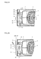
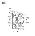
- the clamp device 11 includes: a clamp body 15 having a clamp strip 13 extending along the short-side surface of the plate 7 and configured to be slidable on the plate 7 between a clamping position CP where the clamp strip 13 contacts with the side surface during clamping and an unclamping position UCP where the clamp strip 13 is away from the side surface by a predetermined distance during unclamping; a support shaft 17 provided on the installation space at a position close to the clamp body 15 and extending in the vertical direction; an operating member 25 having a first end, a second end, and an intermediate portion 19 positioned between the first end and the second end and rotatably connected to the support shaft 17, the first end being a connecting end 21 connected to the clamp body 15, and the second end being folded back at the support shaft 17 and being an operating end 23 extending above the clamp body 15, so that the operating member 25 is elastically deformable in an expanding and contracting directions as seen from top between the connecting end 21 and the operating end 23; and an engagement member 27 provided on the installation space opposite to the support shaft 17 with the clamp
- the clamp strip 13 of the clamp body 15 is formed as an elongated plate member whose length is smaller than that of the short-side surface of the plate 7, and the clamp strip 13 is arranged along the side surface of the plate 7. Further, the clamp strip 13 has an extension strip 14 in the shape of a rectangular plate with short sides whose length is smaller than that of the clamp strip 13 and long sides whose length is smaller than the depth of the installation space.
- the extension strip 14 is formed by bending the clamp strip 13 substantially at a right angle and extending from an upper edge portion of the clamp strip 13 so as to be positioned parallel with the installation space surface with a predetermined gap.
- the connecting mechanism 29 includes: a bolt 31 configured to extend from a surface of a center part of the extension strip 14 while penetrating the extension strip 14 and extend toward the installation space surface; a connecting groove 33 with a predetermined length for allowing penetration of the bolt 31 and formed in the installation space along the depth direction of the installation space in alignment with a center line of the plate 7; and a retaining ring member 35 positioned below the connecting groove 33 and into which the lower end of the bolt 31 is screwed.
- the clamp body 15 is connected to the installation space on the plate 7 via a guiding mechanism 37.
- the guiding mechanism 37 is configured to guide the clamp strip 13 in such a manner as to be slidable while maintaining a parallel relationship relative to the side surface of the plate 7.
- the guiding mechanism 37 consists of bent strips 39 formed by bending down both side end portions of the extension strip 14, and guide support members 41 provided on both sides of the connecting groove 33.
- Each guide support member 41 is configured to support the extension strip 14 while contacting with an inner surface of a corresponding bent strip 39 and a lower surface of a corresponding side end portion, so as to guide the bent strip 39 along the connecting groove 33.
- five guide support members 41 protrude from the installation space so that the extension strip 14 is guided along the guide support members 41 while maintaining a predetermined distance from the installation space.
- the operating member 25 is formed by bending an elongated elastically deformable member.
- an intermediate portion 19 of the elongated elastically deformable member is wound around the support shaft 17 approximately for 2.5 turns while allowing a rotation of the intermediate portion 19, and both ends of the elastically deformable member extend orthogonally from the support shaft 17 at different heights.
- one end (first end) positioned below the other end (second end) is wound around and connected to a body portion of the bolt 31 as a connecting end 21 in such a manner as to be rotatable around the bolt 31, whereas the other end (second end) positioned above the first end extends horizontally as an operating end 23.
- the operating member 25 is configured such that when the operating end 23 is operated to rotate around the support shaft 17, the connecting end 21 also rotates in the same direction by the aid of the elastic deformation of the operating member 25 in an expanding and contracting directions between the connecting end 21 and the operating end 23.
- the engagement member 27 is provided on the installation space opposite to the support shaft 17 with the extension strip 14 of the clamp body 15 interposed therebetween.
- the engagement member 27 is a rod-like member having a proximal end and a hook-shaped distal end. The proximal end of the engagement member 27 is fixed to the installation space, and the hook-shaped distal end is engageable with the operating end in such a state where the intermediate portion 19 between the connecting end 21 and the operating end 23 of the operating member 25 is compressed.
- the clamp body 15 is urged toward the unclamping position UCP by the elasticity of the operating member 25.
- one end portion of the sanding sheet 9 is positioned between the clamp strip 13 and the side surface of the plate 7, and then the operating end 23 is operated to rotate horizontally toward the engagement member 27.
- This causes the connecting end 21 to rotate horizontally in the same direction as the operating end 23 does, so that the clamp body 15 engaged with the connecting mechanism 29 can be slid to the clamping position CP (see FIG. 2A ).
- the operating member 25 is rotatable around the support shaft 17 extending in a vertical direction from the plate 7, the operating end 23 extending from the support shaft 17 can be enlarged to the extent of the length of one side of the plate 7, so that the operating load for the clamping operation becomes relatively small.
- the clamp strip 13 released by the operator does not return automatically from the unclamping position UCP to the clamping position CP, setting of the sanding sheet 9 is readily performed.
- the clamp device 11 is arranged on the plate 7, setting of the sanding sheet 9 can be performed on an operation work table.
- the clamp body 15 is connected to the plate 7 via the guiding mechanism 37, which is configured to guide the clamp strip 13 in such a manner as to be slidable while maintaining a parallel relationship relative to the side surface of the plate 7. Therefore, notwithstanding the rotational movement of the operating member 25, the clamp body 15 can perform a smooth linear movement by means of the guiding mechanism 37, and the attachment and/or removal of the sanding sheet 9 can be performed without deteriorating the operability.
Landscapes
- Engineering & Computer Science (AREA)
- Mechanical Engineering (AREA)
- Finish Polishing, Edge Sharpening, And Grinding By Specific Grinding Devices (AREA)
- Constituent Portions Of Griding Lathes, Driving, Sensing And Control (AREA)
Applications Claiming Priority (1)
| Application Number | Priority Date | Filing Date | Title |
|---|---|---|---|
| JP2009056876A JP5275854B2 (ja) | 2009-03-10 | 2009-03-10 | サンダ |
Publications (3)
| Publication Number | Publication Date |
|---|---|
| EP2228174A2 true EP2228174A2 (de) | 2010-09-15 |
| EP2228174A3 EP2228174A3 (de) | 2012-12-19 |
| EP2228174B1 EP2228174B1 (de) | 2013-08-07 |
Family
ID=42115637
Family Applications (1)
| Application Number | Title | Priority Date | Filing Date |
|---|---|---|---|
| EP10001851.4A Not-in-force EP2228174B1 (de) | 2009-03-10 | 2010-02-23 | Schleifmaschine |
Country Status (4)
| Country | Link |
|---|---|
| US (1) | US8251781B2 (de) |
| EP (1) | EP2228174B1 (de) |
| JP (1) | JP5275854B2 (de) |
| RU (1) | RU2521551C2 (de) |
Families Citing this family (10)
| Publication number | Priority date | Publication date | Assignee | Title |
|---|---|---|---|---|
| USD632939S1 (en) * | 2010-03-17 | 2011-02-22 | Makita Corporation | Portable electric sander |
| USD650651S1 (en) * | 2010-04-07 | 2011-12-20 | Makita Corporation | Portable electric sander |
| DE102011084591A1 (de) * | 2011-10-17 | 2013-04-18 | Robert Bosch Gmbh | Werkzeugmaschinenspannvorrichtung |
| JP5788782B2 (ja) * | 2011-12-21 | 2015-10-07 | 株式会社マキタ | サンダ |
| USD677541S1 (en) * | 2012-08-16 | 2013-03-12 | Hutchin Exports Ltd | Sheet sander |
| CN105922107A (zh) * | 2016-06-29 | 2016-09-07 | 苏州博来喜电器有限公司 | 应用于砂光机中的底板组件 |
| USD846962S1 (en) * | 2016-12-13 | 2019-04-30 | Festool Gmbh | Sanding and polishing machine |
| JP1723411S (ja) * | 2021-09-10 | 2022-08-29 | 携帯式電動工具 | |
| JP2025034396A (ja) | 2023-08-31 | 2025-03-13 | 株式会社マキタ | サンダ |
| USD1018233S1 (en) * | 2023-10-09 | 2024-03-19 | Yongkang Baoda Tools Manufacture Co. Ltd | Electric sander |
Citations (1)
| Publication number | Priority date | Publication date | Assignee | Title |
|---|---|---|---|---|
| JPS5320796A (en) | 1976-08-10 | 1978-02-25 | Canon Inc | Liquid crystal display unit |
Family Cites Families (15)
| Publication number | Priority date | Publication date | Assignee | Title |
|---|---|---|---|---|
| US3104503A (en) * | 1961-01-09 | 1963-09-24 | Singer Co | Sander plate assembly for portable sanding tools |
| JPS5320796U (de) | 1976-08-02 | 1978-02-22 | ||
| DE2929618C2 (de) * | 1979-07-21 | 1982-02-04 | Festo-Maschinenfabrik Gottlieb Stoll, 7300 Esslingen | Vibrationshandschleifmaschine |
| JPS57136656U (de) * | 1981-02-18 | 1982-08-26 | ||
| JPS5875658U (ja) * | 1981-11-12 | 1983-05-21 | 日立工機株式会社 | 電気オ−ビタルサンダにおけるサンデイングペ−パの保持構造 |
| SU1263500A1 (ru) * | 1983-07-06 | 1986-10-15 | Всесоюзный Научно-Исследовательский И Проектно-Конструкторский Институт Механизированного И Ручного Строительно-Монтажного Инструмента,Вибраторов И Строительно-Отделочных Машин | Плоскошлифовальна головка |
| DE3403963A1 (de) * | 1984-02-04 | 1985-08-08 | Licentia Patent-Verwaltungs-Gmbh, 6000 Frankfurt | Einrichtung zum festklemmen bzw. freigeben des schleifmitteltraegers an bzw. von der schwingplatte eines handschwingschleifers |
| JPH0215256U (de) * | 1988-07-01 | 1990-01-30 | ||
| JPH0683952B2 (ja) * | 1989-09-05 | 1994-10-26 | 株式会社マキタ | コードレス研摩機 |
| US5902176A (en) * | 1997-10-07 | 1999-05-11 | Chen; Kun-You | Clamping device for a sanding tool |
| JP2000254852A (ja) * | 1999-03-08 | 2000-09-19 | Ryobi Ltd | サンダーのクランプ装置 |
| DE10139548A1 (de) * | 2001-08-10 | 2003-02-20 | Bosch Gmbh Robert | Schleifhandwerkzeugmaschine |
| RU2254978C1 (ru) * | 2003-12-24 | 2005-06-27 | Гой Владимир Леонтьевич | Держатель наждачной бумаги |
| US7134951B1 (en) * | 2005-12-28 | 2006-11-14 | Leon Jess M | Sheet holder for abrasive sheets |
| DE102006035977A1 (de) * | 2006-08-02 | 2008-02-07 | Robert Bosch Gmbh | Schleifhandwerkzeugmaschine mit neuer Schleifblattzugspannung |
-
2009
- 2009-03-10 JP JP2009056876A patent/JP5275854B2/ja not_active Expired - Fee Related
-
2010
- 2010-02-19 US US12/709,025 patent/US8251781B2/en not_active Expired - Fee Related
- 2010-02-23 EP EP10001851.4A patent/EP2228174B1/de not_active Not-in-force
- 2010-03-09 RU RU2010108449/02A patent/RU2521551C2/ru not_active IP Right Cessation
Patent Citations (1)
| Publication number | Priority date | Publication date | Assignee | Title |
|---|---|---|---|---|
| JPS5320796A (en) | 1976-08-10 | 1978-02-25 | Canon Inc | Liquid crystal display unit |
Also Published As
| Publication number | Publication date |
|---|---|
| RU2521551C2 (ru) | 2014-06-27 |
| US8251781B2 (en) | 2012-08-28 |
| EP2228174A3 (de) | 2012-12-19 |
| JP5275854B2 (ja) | 2013-08-28 |
| US20100233944A1 (en) | 2010-09-16 |
| JP2010207964A (ja) | 2010-09-24 |
| EP2228174B1 (de) | 2013-08-07 |
| RU2010108449A (ru) | 2011-09-20 |
Similar Documents
| Publication | Publication Date | Title |
|---|---|---|
| EP2228174A2 (de) | Schleifmaschine | |
| US9016179B2 (en) | Positioning device for a turnable table of saw machine | |
| EP3141352B1 (de) | Kombination von arbeitstisch und zaunanlage und tischschneidemaschine mit der kombination | |
| JP4947904B2 (ja) | 紙裁断機 | |
| JP2002103196A (ja) | 手持ち式電動サンダ | |
| US7784388B2 (en) | Blade clamping device | |
| JP3232783U (ja) | クランプホルダ | |
| US4077165A (en) | Abrading tool clip with automatic take-up | |
| CA2410837A1 (en) | Sanding tool | |
| CN102343524B (zh) | 固定装置 | |
| JP2019005920A (ja) | 定規用アダプタ | |
| CN211805647U (zh) | 治具组拆装置 | |
| JP5123969B2 (ja) | 綴じ具 | |
| JP4762607B2 (ja) | 切断機の案内装置 | |
| JP4634127B2 (ja) | 切断機 | |
| JP3189538U (ja) | 裁断機 | |
| US7134951B1 (en) | Sheet holder for abrasive sheets | |
| JP4623757B2 (ja) | 工具用定規 | |
| JP2021078781A (ja) | 手術台用クランプ | |
| JPH0323171Y2 (de) | ||
| JP4541862B2 (ja) | 切断機 | |
| JP3112806U (ja) | 丸鋸機用角度定規 | |
| JP4913542B2 (ja) | ミシンの押さえ装置 | |
| CN223744745U (zh) | 夹子 | |
| CN111217133A (zh) | 限位装置 |
Legal Events
| Date | Code | Title | Description |
|---|---|---|---|
| PUAI | Public reference made under article 153(3) epc to a published international application that has entered the european phase |
Free format text: ORIGINAL CODE: 0009012 |
|
| AK | Designated contracting states |
Kind code of ref document: A2 Designated state(s): AT BE BG CH CY CZ DE DK EE ES FI FR GB GR HR HU IE IS IT LI LT LU LV MC MK MT NL NO PL PT RO SE SI SK SM TR |
|
| AX | Request for extension of the european patent |
Extension state: AL BA RS |
|
| PUAL | Search report despatched |
Free format text: ORIGINAL CODE: 0009013 |
|
| AK | Designated contracting states |
Kind code of ref document: A3 Designated state(s): AT BE BG CH CY CZ DE DK EE ES FI FR GB GR HR HU IE IS IT LI LT LU LV MC MK MT NL NO PL PT RO SE SI SK SM TR |
|
| AX | Request for extension of the european patent |
Extension state: AL BA RS |
|
| RIC1 | Information provided on ipc code assigned before grant |
Ipc: B24B 23/04 20060101AFI20121115BHEP |
|
| GRAP | Despatch of communication of intention to grant a patent |
Free format text: ORIGINAL CODE: EPIDOSNIGR1 |
|
| 17P | Request for examination filed |
Effective date: 20130327 |
|
| RIC1 | Information provided on ipc code assigned before grant |
Ipc: B24B 23/04 20060101AFI20130418BHEP |
|
| INTG | Intention to grant announced |
Effective date: 20130506 |
|
| GRAS | Grant fee paid |
Free format text: ORIGINAL CODE: EPIDOSNIGR3 |
|
| GRAA | (expected) grant |
Free format text: ORIGINAL CODE: 0009210 |
|
| AK | Designated contracting states |
Kind code of ref document: B1 Designated state(s): AT BE BG CH CY CZ DE DK EE ES FI FR GB GR HR HU IE IS IT LI LT LU LV MC MK MT NL NO PL PT RO SE SI SK SM TR |
|
| REG | Reference to a national code |
Ref country code: GB Ref legal event code: FG4D |
|
| REG | Reference to a national code |
Ref country code: CH Ref legal event code: EP Ref country code: AT Ref legal event code: REF Ref document number: 625533 Country of ref document: AT Kind code of ref document: T Effective date: 20130815 |
|
| REG | Reference to a national code |
Ref country code: IE Ref legal event code: FG4D |
|
| REG | Reference to a national code |
Ref country code: DE Ref legal event code: R096 Ref document number: 602010009138 Country of ref document: DE Effective date: 20131002 |
|
| REG | Reference to a national code |
Ref country code: AT Ref legal event code: MK05 Ref document number: 625533 Country of ref document: AT Kind code of ref document: T Effective date: 20130807 |
|
| REG | Reference to a national code |
Ref country code: NL Ref legal event code: VDEP Effective date: 20130807 |
|
| REG | Reference to a national code |
Ref country code: LT Ref legal event code: MG4D |
|
| PG25 | Lapsed in a contracting state [announced via postgrant information from national office to epo] |
Ref country code: IS Free format text: LAPSE BECAUSE OF FAILURE TO SUBMIT A TRANSLATION OF THE DESCRIPTION OR TO PAY THE FEE WITHIN THE PRESCRIBED TIME-LIMIT Effective date: 20131207 Ref country code: CY Free format text: LAPSE BECAUSE OF FAILURE TO SUBMIT A TRANSLATION OF THE DESCRIPTION OR TO PAY THE FEE WITHIN THE PRESCRIBED TIME-LIMIT Effective date: 20130904 Ref country code: SE Free format text: LAPSE BECAUSE OF FAILURE TO SUBMIT A TRANSLATION OF THE DESCRIPTION OR TO PAY THE FEE WITHIN THE PRESCRIBED TIME-LIMIT Effective date: 20130807 Ref country code: AT Free format text: LAPSE BECAUSE OF FAILURE TO SUBMIT A TRANSLATION OF THE DESCRIPTION OR TO PAY THE FEE WITHIN THE PRESCRIBED TIME-LIMIT Effective date: 20130807 Ref country code: HR Free format text: LAPSE BECAUSE OF FAILURE TO SUBMIT A TRANSLATION OF THE DESCRIPTION OR TO PAY THE FEE WITHIN THE PRESCRIBED TIME-LIMIT Effective date: 20130807 Ref country code: NO Free format text: LAPSE BECAUSE OF FAILURE TO SUBMIT A TRANSLATION OF THE DESCRIPTION OR TO PAY THE FEE WITHIN THE PRESCRIBED TIME-LIMIT Effective date: 20131107 Ref country code: LT Free format text: LAPSE BECAUSE OF FAILURE TO SUBMIT A TRANSLATION OF THE DESCRIPTION OR TO PAY THE FEE WITHIN THE PRESCRIBED TIME-LIMIT Effective date: 20130807 Ref country code: PT Free format text: LAPSE BECAUSE OF FAILURE TO SUBMIT A TRANSLATION OF THE DESCRIPTION OR TO PAY THE FEE WITHIN THE PRESCRIBED TIME-LIMIT Effective date: 20131209 |
|
| PG25 | Lapsed in a contracting state [announced via postgrant information from national office to epo] |
Ref country code: SI Free format text: LAPSE BECAUSE OF FAILURE TO SUBMIT A TRANSLATION OF THE DESCRIPTION OR TO PAY THE FEE WITHIN THE PRESCRIBED TIME-LIMIT Effective date: 20130807 Ref country code: GR Free format text: LAPSE BECAUSE OF FAILURE TO SUBMIT A TRANSLATION OF THE DESCRIPTION OR TO PAY THE FEE WITHIN THE PRESCRIBED TIME-LIMIT Effective date: 20131108 Ref country code: PL Free format text: LAPSE BECAUSE OF FAILURE TO SUBMIT A TRANSLATION OF THE DESCRIPTION OR TO PAY THE FEE WITHIN THE PRESCRIBED TIME-LIMIT Effective date: 20130807 Ref country code: LV Free format text: LAPSE BECAUSE OF FAILURE TO SUBMIT A TRANSLATION OF THE DESCRIPTION OR TO PAY THE FEE WITHIN THE PRESCRIBED TIME-LIMIT Effective date: 20130807 Ref country code: BE Free format text: LAPSE BECAUSE OF FAILURE TO SUBMIT A TRANSLATION OF THE DESCRIPTION OR TO PAY THE FEE WITHIN THE PRESCRIBED TIME-LIMIT Effective date: 20130807 Ref country code: FI Free format text: LAPSE BECAUSE OF FAILURE TO SUBMIT A TRANSLATION OF THE DESCRIPTION OR TO PAY THE FEE WITHIN THE PRESCRIBED TIME-LIMIT Effective date: 20130807 Ref country code: NL Free format text: LAPSE BECAUSE OF FAILURE TO SUBMIT A TRANSLATION OF THE DESCRIPTION OR TO PAY THE FEE WITHIN THE PRESCRIBED TIME-LIMIT Effective date: 20130807 |
|
| PG25 | Lapsed in a contracting state [announced via postgrant information from national office to epo] |
Ref country code: CY Free format text: LAPSE BECAUSE OF FAILURE TO SUBMIT A TRANSLATION OF THE DESCRIPTION OR TO PAY THE FEE WITHIN THE PRESCRIBED TIME-LIMIT Effective date: 20130807 |
|
| PG25 | Lapsed in a contracting state [announced via postgrant information from national office to epo] |
Ref country code: DK Free format text: LAPSE BECAUSE OF FAILURE TO SUBMIT A TRANSLATION OF THE DESCRIPTION OR TO PAY THE FEE WITHIN THE PRESCRIBED TIME-LIMIT Effective date: 20130807 Ref country code: RO Free format text: LAPSE BECAUSE OF FAILURE TO SUBMIT A TRANSLATION OF THE DESCRIPTION OR TO PAY THE FEE WITHIN THE PRESCRIBED TIME-LIMIT Effective date: 20130807 Ref country code: CZ Free format text: LAPSE BECAUSE OF FAILURE TO SUBMIT A TRANSLATION OF THE DESCRIPTION OR TO PAY THE FEE WITHIN THE PRESCRIBED TIME-LIMIT Effective date: 20130807 Ref country code: SK Free format text: LAPSE BECAUSE OF FAILURE TO SUBMIT A TRANSLATION OF THE DESCRIPTION OR TO PAY THE FEE WITHIN THE PRESCRIBED TIME-LIMIT Effective date: 20130807 Ref country code: EE Free format text: LAPSE BECAUSE OF FAILURE TO SUBMIT A TRANSLATION OF THE DESCRIPTION OR TO PAY THE FEE WITHIN THE PRESCRIBED TIME-LIMIT Effective date: 20130807 |
|
| PG25 | Lapsed in a contracting state [announced via postgrant information from national office to epo] |
Ref country code: ES Free format text: LAPSE BECAUSE OF FAILURE TO SUBMIT A TRANSLATION OF THE DESCRIPTION OR TO PAY THE FEE WITHIN THE PRESCRIBED TIME-LIMIT Effective date: 20130807 Ref country code: IT Free format text: LAPSE BECAUSE OF FAILURE TO SUBMIT A TRANSLATION OF THE DESCRIPTION OR TO PAY THE FEE WITHIN THE PRESCRIBED TIME-LIMIT Effective date: 20130807 |
|
| PLBE | No opposition filed within time limit |
Free format text: ORIGINAL CODE: 0009261 |
|
| STAA | Information on the status of an ep patent application or granted ep patent |
Free format text: STATUS: NO OPPOSITION FILED WITHIN TIME LIMIT |
|
| 26N | No opposition filed |
Effective date: 20140508 |
|
| REG | Reference to a national code |
Ref country code: DE Ref legal event code: R097 Ref document number: 602010009138 Country of ref document: DE Effective date: 20140508 |
|
| PG25 | Lapsed in a contracting state [announced via postgrant information from national office to epo] |
Ref country code: MC Free format text: LAPSE BECAUSE OF FAILURE TO SUBMIT A TRANSLATION OF THE DESCRIPTION OR TO PAY THE FEE WITHIN THE PRESCRIBED TIME-LIMIT Effective date: 20130807 Ref country code: LU Free format text: LAPSE BECAUSE OF FAILURE TO SUBMIT A TRANSLATION OF THE DESCRIPTION OR TO PAY THE FEE WITHIN THE PRESCRIBED TIME-LIMIT Effective date: 20140223 |
|
| REG | Reference to a national code |
Ref country code: CH Ref legal event code: PL |
|
| PG25 | Lapsed in a contracting state [announced via postgrant information from national office to epo] |
Ref country code: CH Free format text: LAPSE BECAUSE OF NON-PAYMENT OF DUE FEES Effective date: 20140228 Ref country code: LI Free format text: LAPSE BECAUSE OF NON-PAYMENT OF DUE FEES Effective date: 20140228 |
|
| REG | Reference to a national code |
Ref country code: IE Ref legal event code: MM4A |
|
| PG25 | Lapsed in a contracting state [announced via postgrant information from national office to epo] |
Ref country code: IE Free format text: LAPSE BECAUSE OF NON-PAYMENT OF DUE FEES Effective date: 20140223 |
|
| REG | Reference to a national code |
Ref country code: FR Ref legal event code: PLFP Year of fee payment: 7 |
|
| PG25 | Lapsed in a contracting state [announced via postgrant information from national office to epo] |
Ref country code: MT Free format text: LAPSE BECAUSE OF FAILURE TO SUBMIT A TRANSLATION OF THE DESCRIPTION OR TO PAY THE FEE WITHIN THE PRESCRIBED TIME-LIMIT Effective date: 20130807 |
|
| PG25 | Lapsed in a contracting state [announced via postgrant information from national office to epo] |
Ref country code: SM Free format text: LAPSE BECAUSE OF FAILURE TO SUBMIT A TRANSLATION OF THE DESCRIPTION OR TO PAY THE FEE WITHIN THE PRESCRIBED TIME-LIMIT Effective date: 20130807 |
|
| PG25 | Lapsed in a contracting state [announced via postgrant information from national office to epo] |
Ref country code: BG Free format text: LAPSE BECAUSE OF FAILURE TO SUBMIT A TRANSLATION OF THE DESCRIPTION OR TO PAY THE FEE WITHIN THE PRESCRIBED TIME-LIMIT Effective date: 20130807 |
|
| PG25 | Lapsed in a contracting state [announced via postgrant information from national office to epo] |
Ref country code: TR Free format text: LAPSE BECAUSE OF FAILURE TO SUBMIT A TRANSLATION OF THE DESCRIPTION OR TO PAY THE FEE WITHIN THE PRESCRIBED TIME-LIMIT Effective date: 20130807 Ref country code: HU Free format text: LAPSE BECAUSE OF FAILURE TO SUBMIT A TRANSLATION OF THE DESCRIPTION OR TO PAY THE FEE WITHIN THE PRESCRIBED TIME-LIMIT; INVALID AB INITIO Effective date: 20100223 |
|
| REG | Reference to a national code |
Ref country code: FR Ref legal event code: PLFP Year of fee payment: 8 |
|
| PGFP | Annual fee paid to national office [announced via postgrant information from national office to epo] |
Ref country code: FR Payment date: 20170112 Year of fee payment: 8 Ref country code: DE Payment date: 20170214 Year of fee payment: 8 |
|
| PGFP | Annual fee paid to national office [announced via postgrant information from national office to epo] |
Ref country code: GB Payment date: 20170222 Year of fee payment: 8 |
|
| PG25 | Lapsed in a contracting state [announced via postgrant information from national office to epo] |
Ref country code: MK Free format text: LAPSE BECAUSE OF FAILURE TO SUBMIT A TRANSLATION OF THE DESCRIPTION OR TO PAY THE FEE WITHIN THE PRESCRIBED TIME-LIMIT Effective date: 20130807 |
|
| REG | Reference to a national code |
Ref country code: DE Ref legal event code: R119 Ref document number: 602010009138 Country of ref document: DE |
|
| GBPC | Gb: european patent ceased through non-payment of renewal fee |
Effective date: 20180223 |
|
| REG | Reference to a national code |
Ref country code: FR Ref legal event code: ST Effective date: 20181031 |
|
| PG25 | Lapsed in a contracting state [announced via postgrant information from national office to epo] |
Ref country code: DE Free format text: LAPSE BECAUSE OF NON-PAYMENT OF DUE FEES Effective date: 20180901 |
|
| PG25 | Lapsed in a contracting state [announced via postgrant information from national office to epo] |
Ref country code: GB Free format text: LAPSE BECAUSE OF NON-PAYMENT OF DUE FEES Effective date: 20180223 Ref country code: FR Free format text: LAPSE BECAUSE OF NON-PAYMENT OF DUE FEES Effective date: 20180228 |