EP2228174A2 - Sander - Google Patents
Sander Download PDFInfo
- Publication number
- EP2228174A2 EP2228174A2 EP10001851A EP10001851A EP2228174A2 EP 2228174 A2 EP2228174 A2 EP 2228174A2 EP 10001851 A EP10001851 A EP 10001851A EP 10001851 A EP10001851 A EP 10001851A EP 2228174 A2 EP2228174 A2 EP 2228174A2
- Authority
- EP
- European Patent Office
- Prior art keywords
- plate
- clamp
- strip
- operating
- sander according
- Prior art date
- Legal status (The legal status is an assumption and is not a legal conclusion. Google has not performed a legal analysis and makes no representation as to the accuracy of the status listed.)
- Granted
Links
Images


Classifications
-
- B—PERFORMING OPERATIONS; TRANSPORTING
- B24—GRINDING; POLISHING
- B24B—MACHINES, DEVICES, OR PROCESSES FOR GRINDING OR POLISHING; DRESSING OR CONDITIONING OF ABRADING SURFACES; FEEDING OF GRINDING, POLISHING, OR LAPPING AGENTS
- B24B23/00—Portable grinding machines, e.g. hand-guided; Accessories therefor
- B24B23/04—Portable grinding machines, e.g. hand-guided; Accessories therefor with oscillating grinding tools; Accessories therefor
- B24B23/046—Clamping or tensioning means for abrasive sheets
Definitions
- the present invention relates to a sander equipped with a clamp device for a sanding sheet.
- Japanese Utility Model Publication No. S53-020796 discloses a paper clamping device for a sander.
- the paper clamping device comprises a metal clamp 15 provided on a plate 8 through a spring 20 so as to be urged in a closed direction by the resilient force of the spring 20, and an elastic material 21 positioned between the metal clamp 15 and a paper-hanging plate 14 protruding upward from an end portion of a sanding plate 9.
- a paper 13 is clamped between the elastic material 21 and the metal clamp 15, and when the elastic material 21 undergoes a compressive deformation, the paper 13 is further pulled and tensed in accordance with the amount of compressive deformation.
- the metal clamp 15 is configured such that an operating plate member 17 is rotatable around a pivot axis 19 which is transversely mounted on the sanding plate 9 via a bracket 18. For this reason, the operating plate member 17 has to extend upward from the sanding plate 9. This may disadvantageously cause an operator to operate the operating plate member 17 by mistake during the sanding operation. However, reducing the length of the operating plate member 17 would result in an increase in the operating load for the operating plate member 17, so that the operator is required a great deal of effort for a single-handed operation and thus the setting operation becomes arduous.
- the operating plate member 17 if the operator releases his hand from the operating plate member 17, the operating plate member 17 returns to the clamping position by the resilient action of the spring 20. Therefore, upon attachment and/or removal of the paper 13, the operator is always required to hold the operating plate member 17 in the unclamping position. This results in deterioration of the operability.
- the present invention seeks to provide a sander which can reduce the operating load without decreasing reliability for clamping a sanding sheet as well as ease the setting operation.
- the present invention has been made in an attempt to eliminate the above disadvantages, and illustrative, non-limiting embodiments of the present invention overcome the above disadvantages and other disadvantages not described above.
- a sander comprising: a main body in which a motor is housed; a rectangular plate provided below the main body and configured to move in a circular motion on a flat plane when the motor is driven; and a pair of clamp devices provided at opposite side surfaces of the plate, each clamp device being configured to be capable of clamping one end portion of a sanding sheet to be positioned on a bottom surface of the plate.
- Each clamp device comprises: a clamp body having a clamp strip extending along the side surface of the plate and configured to be slidable on the plate between a clamping position where the clamp strip contacts with the side surface and an unclamping position where the clamp strip is away from the side surface; a support shaft provided on the plate at a position close to the clamp body and extending in a vertical direction; an operating member having a first end, a second end, and an intermediate portion positioned between the first end and the second end and rotatably connected to the support shaft, the first end being a connecting end connected to the clamp body, and the second end being folded back at the support shaft and being an operating end extending above the clamp body, so that the operating member is elastically deformable in an expanding and contracting directions as seen from top between the connecting end and the operating end; and an engagement member provided on the plate opposite to the support shaft with the clamp body interposed therebetween, and configured to be engageable with the operating end of the operating member while the intermediate portion is being compressed, wherein while the end portion of the sand
- the clamp body is connected to the plate via a guiding mechanism, and the guiding mechanism is configured to guide the clamp strip in such a manner as to be slidable while maintaining a parallel relationship relative to the side surface of the plate.
- the operating member is rotatable around the support shaft extending in a vertical direction from the plate, the operating end extending from the support shaft can be enlarged to the extent of the length of one side of the plate, so that the operating load for the clamping operation becomes relatively small. Further, since the clamp strip released by the operator does not return automatically from the unclamping position to the clamping position, setting of the sanding sheet is readily performed.
- the clamp body can perform a smooth linear movement by means of the guiding mechanism. Therefore, attachment and/or removal of the sanding sheet can be performed without deteriorating the operability.
- a sander 1 mainly consists of a main body 5 having a housing 3 in which a motor 2 is housed, and a rectangular plate 7 provided below the main body 5 and configured to move in a circular motion on a flat plane when the motor 2 is driven.
- the main body 5 is arranged substantially at a center part of the plate 7.
- the plate 7 is formed to have a predetermined thickness, and has two opposite short sides and two opposite long sides.
- the sander 1 is equipped with a pair of clamp devices 11, 11 provided at opposite short-side surfaces of the plate 7. Each clamp device 11 is configured to be capable of clamping one end portion of a sanding sheet 9 to be positioned on a bottom surface of the plate 7.
- the clamp device 11 is arranged at an installation space on the plate 7, which extends from the short-side surface of the plate 7 to the main body 5 with a predetermined depth.
- the clamp device 11 includes: a clamp body 15 having a clamp strip 13 extending along the short-side surface of the plate 7 and configured to be slidable on the plate 7 between a clamping position CP where the clamp strip 13 contacts with the side surface during clamping and an unclamping position UCP where the clamp strip 13 is away from the side surface by a predetermined distance during unclamping; a support shaft 17 provided on the installation space at a position close to the clamp body 15 and extending in the vertical direction; an operating member 25 having a first end, a second end, and an intermediate portion 19 positioned between the first end and the second end and rotatably connected to the support shaft 17, the first end being a connecting end 21 connected to the clamp body 15, and the second end being folded back at the support shaft 17 and being an operating end 23 extending above the clamp body 15, so that the operating member 25 is elastically deformable in an expanding and contracting directions as seen from top between the connecting end 21 and the operating end 23; and an engagement member 27 provided on the installation space opposite to the support shaft 17 with the clamp
- the clamp strip 13 of the clamp body 15 is formed as an elongated plate member whose length is smaller than that of the short-side surface of the plate 7, and the clamp strip 13 is arranged along the side surface of the plate 7. Further, the clamp strip 13 has an extension strip 14 in the shape of a rectangular plate with short sides whose length is smaller than that of the clamp strip 13 and long sides whose length is smaller than the depth of the installation space.
- the extension strip 14 is formed by bending the clamp strip 13 substantially at a right angle and extending from an upper edge portion of the clamp strip 13 so as to be positioned parallel with the installation space surface with a predetermined gap.
- the connecting mechanism 29 includes: a bolt 31 configured to extend from a surface of a center part of the extension strip 14 while penetrating the extension strip 14 and extend toward the installation space surface; a connecting groove 33 with a predetermined length for allowing penetration of the bolt 31 and formed in the installation space along the depth direction of the installation space in alignment with a center line of the plate 7; and a retaining ring member 35 positioned below the connecting groove 33 and into which the lower end of the bolt 31 is screwed.
- the clamp body 15 is connected to the installation space on the plate 7 via a guiding mechanism 37.
- the guiding mechanism 37 is configured to guide the clamp strip 13 in such a manner as to be slidable while maintaining a parallel relationship relative to the side surface of the plate 7.
- the guiding mechanism 37 consists of bent strips 39 formed by bending down both side end portions of the extension strip 14, and guide support members 41 provided on both sides of the connecting groove 33.
- Each guide support member 41 is configured to support the extension strip 14 while contacting with an inner surface of a corresponding bent strip 39 and a lower surface of a corresponding side end portion, so as to guide the bent strip 39 along the connecting groove 33.
- five guide support members 41 protrude from the installation space so that the extension strip 14 is guided along the guide support members 41 while maintaining a predetermined distance from the installation space.
- the operating member 25 is formed by bending an elongated elastically deformable member.
- an intermediate portion 19 of the elongated elastically deformable member is wound around the support shaft 17 approximately for 2.5 turns while allowing a rotation of the intermediate portion 19, and both ends of the elastically deformable member extend orthogonally from the support shaft 17 at different heights.
- one end (first end) positioned below the other end (second end) is wound around and connected to a body portion of the bolt 31 as a connecting end 21 in such a manner as to be rotatable around the bolt 31, whereas the other end (second end) positioned above the first end extends horizontally as an operating end 23.
- the operating member 25 is configured such that when the operating end 23 is operated to rotate around the support shaft 17, the connecting end 21 also rotates in the same direction by the aid of the elastic deformation of the operating member 25 in an expanding and contracting directions between the connecting end 21 and the operating end 23.
- the engagement member 27 is provided on the installation space opposite to the support shaft 17 with the extension strip 14 of the clamp body 15 interposed therebetween.
- the engagement member 27 is a rod-like member having a proximal end and a hook-shaped distal end. The proximal end of the engagement member 27 is fixed to the installation space, and the hook-shaped distal end is engageable with the operating end in such a state where the intermediate portion 19 between the connecting end 21 and the operating end 23 of the operating member 25 is compressed.
- the clamp body 15 is urged toward the unclamping position UCP by the elasticity of the operating member 25.
- one end portion of the sanding sheet 9 is positioned between the clamp strip 13 and the side surface of the plate 7, and then the operating end 23 is operated to rotate horizontally toward the engagement member 27.
- This causes the connecting end 21 to rotate horizontally in the same direction as the operating end 23 does, so that the clamp body 15 engaged with the connecting mechanism 29 can be slid to the clamping position CP (see FIG. 2A ).
- the operating member 25 is rotatable around the support shaft 17 extending in a vertical direction from the plate 7, the operating end 23 extending from the support shaft 17 can be enlarged to the extent of the length of one side of the plate 7, so that the operating load for the clamping operation becomes relatively small.
- the clamp strip 13 released by the operator does not return automatically from the unclamping position UCP to the clamping position CP, setting of the sanding sheet 9 is readily performed.
- the clamp device 11 is arranged on the plate 7, setting of the sanding sheet 9 can be performed on an operation work table.
- the clamp body 15 is connected to the plate 7 via the guiding mechanism 37, which is configured to guide the clamp strip 13 in such a manner as to be slidable while maintaining a parallel relationship relative to the side surface of the plate 7. Therefore, notwithstanding the rotational movement of the operating member 25, the clamp body 15 can perform a smooth linear movement by means of the guiding mechanism 37, and the attachment and/or removal of the sanding sheet 9 can be performed without deteriorating the operability.
Abstract
Description
- The present invention relates to a sander equipped with a clamp device for a sanding sheet.
- Various techniques for sanders have been disclosed in the art for clamping a sanding sheet with respect to a sander. For example, Japanese Utility Model Publication No.
S53-020796 metal clamp 15 provided on a plate 8 through a spring 20 so as to be urged in a closed direction by the resilient force of the spring 20, and anelastic material 21 positioned between themetal clamp 15 and a paper-hangingplate 14 protruding upward from an end portion of asanding plate 9. Apaper 13 is clamped between theelastic material 21 and themetal clamp 15, and when theelastic material 21 undergoes a compressive deformation, thepaper 13 is further pulled and tensed in accordance with the amount of compressive deformation. - However, according to the aforementioned paper clamping device disclosed in Japanese Utility Model Publication No.
S53-020796 metal clamp 15 is configured such that anoperating plate member 17 is rotatable around apivot axis 19 which is transversely mounted on thesanding plate 9 via a bracket 18. For this reason, theoperating plate member 17 has to extend upward from thesanding plate 9. This may disadvantageously cause an operator to operate theoperating plate member 17 by mistake during the sanding operation. However, reducing the length of theoperating plate member 17 would result in an increase in the operating load for theoperating plate member 17, so that the operator is required a great deal of effort for a single-handed operation and thus the setting operation becomes arduous. Especially, if the operator releases his hand from theoperating plate member 17, theoperating plate member 17 returns to the clamping position by the resilient action of the spring 20. Therefore, upon attachment and/or removal of thepaper 13, the operator is always required to hold theoperating plate member 17 in the unclamping position. This results in deterioration of the operability. - In view of the above disadvantages, the present invention seeks to provide a sander which can reduce the operating load without decreasing reliability for clamping a sanding sheet as well as ease the setting operation.
- The present invention has been made in an attempt to eliminate the above disadvantages, and illustrative, non-limiting embodiments of the present invention overcome the above disadvantages and other disadvantages not described above.
- In order to achieve the above object, according to the present invention, there is provided a sander comprising: a main body in which a motor is housed; a rectangular plate provided below the main body and configured to move in a circular motion on a flat plane when the motor is driven; and a pair of clamp devices provided at opposite side surfaces of the plate, each clamp device being configured to be capable of clamping one end portion of a sanding sheet to be positioned on a bottom surface of the plate. Each clamp device comprises: a clamp body having a clamp strip extending along the side surface of the plate and configured to be slidable on the plate between a clamping position where the clamp strip contacts with the side surface and an unclamping position where the clamp strip is away from the side surface; a support shaft provided on the plate at a position close to the clamp body and extending in a vertical direction; an operating member having a first end, a second end, and an intermediate portion positioned between the first end and the second end and rotatably connected to the support shaft, the first end being a connecting end connected to the clamp body, and the second end being folded back at the support shaft and being an operating end extending above the clamp body, so that the operating member is elastically deformable in an expanding and contracting directions as seen from top between the connecting end and the operating end; and an engagement member provided on the plate opposite to the support shaft with the clamp body interposed therebetween, and configured to be engageable with the operating end of the operating member while the intermediate portion is being compressed, wherein while the end portion of the sanding sheet is positioned between the clamp strip and the side surface of the plate, the operating end is brought into engagement with the engagement member so that the intermediate portion is compressed and the clamp body connected to the connecting end is urged from the unclamping position to the clamping position to thereby secure the end portion under pressure between the clamp strip and the side surface of the plate.
- According to one specific embodiment of the present invention, the clamp body is connected to the plate via a guiding mechanism, and the guiding mechanism is configured to guide the clamp strip in such a manner as to be slidable while maintaining a parallel relationship relative to the side surface of the plate.
- With the above configuration of the sander according to the present invention, since the operating member is rotatable around the support shaft extending in a vertical direction from the plate, the operating end extending from the support shaft can be enlarged to the extent of the length of one side of the plate, so that the operating load for the clamping operation becomes relatively small. Further, since the clamp strip released by the operator does not return automatically from the unclamping position to the clamping position, setting of the sanding sheet is readily performed.
- With the above configuration of the sander according to one specific embodiment of the present invention, in addition to the above advantageous effects of the present invention, notwithstanding the rotational movement of the operating member, the clamp body can perform a smooth linear movement by means of the guiding mechanism. Therefore, attachment and/or removal of the sanding sheet can be performed without deteriorating the operability.
- The above aspect, other advantages and further features of the present invention will become more apparent by describing in detail illustrative, non-limiting embodiments thereof with reference to the accompanying drawings, in which:
-
FIG. 1A is a perspective view of a sander according to the present invention explaining that a clamp device is in a clamping position; -
FIG. 1B is a perspective view partially showing the clamp device in an unclamping position; -
FIG. 2A is a top view partially showing the clamp device in the clamping position; -
FIG. 2B is a top view partially showing the clamp device in the unclamping position; -
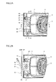
FIG. 3A is an enlarged sectional view taken along the line A-A ofFIG. 2A ; -
FIG. 3B is an enlarged sectional view taken along the line B-B ofFIG. 2A ; -
FIG. 4 is a sectional view taken along the line C-C ofFIGS. 3A and 3B ; and -
FIG. 5 is a perspective view similar toFIG. 2A but a clamp body of the clamp device is removed. - With reference to the accompanying drawings, one preferred embodiment of the present invention will be described in detail.
- As seen in
FIG. 1 , a sander 1 mainly consists of amain body 5 having ahousing 3 in which amotor 2 is housed, and arectangular plate 7 provided below themain body 5 and configured to move in a circular motion on a flat plane when themotor 2 is driven. Themain body 5 is arranged substantially at a center part of theplate 7. Theplate 7 is formed to have a predetermined thickness, and has two opposite short sides and two opposite long sides. Further, the sander 1 is equipped with a pair ofclamp devices plate 7. Eachclamp device 11 is configured to be capable of clamping one end portion of asanding sheet 9 to be positioned on a bottom surface of theplate 7. - As seen in
FIGS. 2A, 2B ,3A and 3B , theclamp device 11 is arranged at an installation space on theplate 7, which extends from the short-side surface of theplate 7 to themain body 5 with a predetermined depth. - The
clamp device 11 includes: aclamp body 15 having aclamp strip 13 extending along the short-side surface of theplate 7 and configured to be slidable on theplate 7 between a clamping position CP where theclamp strip 13 contacts with the side surface during clamping and an unclamping position UCP where theclamp strip 13 is away from the side surface by a predetermined distance during unclamping; asupport shaft 17 provided on the installation space at a position close to theclamp body 15 and extending in the vertical direction; anoperating member 25 having a first end, a second end, and anintermediate portion 19 positioned between the first end and the second end and rotatably connected to thesupport shaft 17, the first end being a connectingend 21 connected to theclamp body 15, and the second end being folded back at thesupport shaft 17 and being an operatingend 23 extending above theclamp body 15, so that theoperating member 25 is elastically deformable in an expanding and contracting directions as seen from top between the connectingend 21 and the operatingend 23; and anengagement member 27 provided on the installation space opposite to thesupport shaft 17 with theclamp body 15 interposed therebetween, and configured to be engageable with the operatingend 23 of theoperating member 25 while theintermediate portion 19 is being compressed. - The
clamp strip 13 of theclamp body 15 is formed as an elongated plate member whose length is smaller than that of the short-side surface of theplate 7, and theclamp strip 13 is arranged along the side surface of theplate 7. Further, theclamp strip 13 has anextension strip 14 in the shape of a rectangular plate with short sides whose length is smaller than that of theclamp strip 13 and long sides whose length is smaller than the depth of the installation space. Theextension strip 14 is formed by bending theclamp strip 13 substantially at a right angle and extending from an upper edge portion of theclamp strip 13 so as to be positioned parallel with the installation space surface with a predetermined gap. - As seen in
FIGS. 3A, 3B andFIG. 4 , theclamp body 15 is engaged with aconnecting mechanism 29 and slidable on the installation space between the clamping position CP and the unclamping position UCP. Theconnecting mechanism 29 includes: abolt 31 configured to extend from a surface of a center part of theextension strip 14 while penetrating theextension strip 14 and extend toward the installation space surface; a connectinggroove 33 with a predetermined length for allowing penetration of thebolt 31 and formed in the installation space along the depth direction of the installation space in alignment with a center line of theplate 7; and aretaining ring member 35 positioned below the connectinggroove 33 and into which the lower end of thebolt 31 is screwed. - The
clamp body 15 is connected to the installation space on theplate 7 via a guidingmechanism 37. The guidingmechanism 37 is configured to guide theclamp strip 13 in such a manner as to be slidable while maintaining a parallel relationship relative to the side surface of theplate 7. The guidingmechanism 37 consists ofbent strips 39 formed by bending down both side end portions of theextension strip 14, and guidesupport members 41 provided on both sides of the connectinggroove 33. Eachguide support member 41 is configured to support theextension strip 14 while contacting with an inner surface of a correspondingbent strip 39 and a lower surface of a corresponding side end portion, so as to guide thebent strip 39 along the connectinggroove 33. - As best seen in
FIG. 5 , fiveguide support members 41 protrude from the installation space so that theextension strip 14 is guided along theguide support members 41 while maintaining a predetermined distance from the installation space. - The operating
member 25 is formed by bending an elongated elastically deformable member. To be more specific, anintermediate portion 19 of the elongated elastically deformable member is wound around thesupport shaft 17 approximately for 2.5 turns while allowing a rotation of theintermediate portion 19, and both ends of the elastically deformable member extend orthogonally from thesupport shaft 17 at different heights. Of these ends of the elastically deformable member, one end (first end) positioned below the other end (second end) is wound around and connected to a body portion of thebolt 31 as a connectingend 21 in such a manner as to be rotatable around thebolt 31, whereas the other end (second end) positioned above the first end extends horizontally as an operatingend 23. The operatingmember 25 is configured such that when the operatingend 23 is operated to rotate around thesupport shaft 17, the connectingend 21 also rotates in the same direction by the aid of the elastic deformation of the operatingmember 25 in an expanding and contracting directions between the connectingend 21 and the operatingend 23. - The
engagement member 27 is provided on the installation space opposite to thesupport shaft 17 with theextension strip 14 of theclamp body 15 interposed therebetween. Theengagement member 27 is a rod-like member having a proximal end and a hook-shaped distal end. The proximal end of theengagement member 27 is fixed to the installation space, and the hook-shaped distal end is engageable with the operating end in such a state where theintermediate portion 19 between the connectingend 21 and the operatingend 23 of the operatingmember 25 is compressed. - According to the sander 1 as described above, when the operating
member 23 is not engaged with theengagement member 27, as best seen inFIG. 2B , theclamp body 15 is urged toward the unclamping position UCP by the elasticity of the operatingmember 25. Upon attachment of thesanding sheet 9, one end portion of thesanding sheet 9 is positioned between theclamp strip 13 and the side surface of theplate 7, and then the operatingend 23 is operated to rotate horizontally toward theengagement member 27. This causes the connectingend 21 to rotate horizontally in the same direction as the operatingend 23 does, so that theclamp body 15 engaged with the connectingmechanism 29 can be slid to the clamping position CP (seeFIG. 2A ). When the operatingend 23 is further rotated against the elasticity of the operatingmember 25 and brought into engagement with theengagement member 27, theclamp body 15 is urged toward the clamping position CP by the elasticity of the operatingmember 25 so that thesanding sheet 9 is tightly secured while being pressed between theclamp strip 13 and the side surface of theplate 7. - On the contrary, upon removal of the
sanding sheet 9, the operatingend 23 is disengaged from theengagement member 27. This causes the operatingend 23 to rotate outward in the horizontal direction by the elastic deformation of the operatingmember 25, so thatclamp body 15 is slid toward the unclamping position UCP. Therefore, the tightly securement of thesanding sheet 9 between theclamp strip 13 and the side surface of theplate 7 is disengaged, allowing replacement of thesanding sheet 9. - According to the sander 1 as described in the above embodiment, since the operating
member 25 is rotatable around thesupport shaft 17 extending in a vertical direction from theplate 7, the operatingend 23 extending from thesupport shaft 17 can be enlarged to the extent of the length of one side of theplate 7, so that the operating load for the clamping operation becomes relatively small. Further, since theclamp strip 13 released by the operator does not return automatically from the unclamping position UCP to the clamping position CP, setting of thesanding sheet 9 is readily performed. Furthermore, since theclamp device 11 is arranged on theplate 7, setting of thesanding sheet 9 can be performed on an operation work table. - Further, the
clamp body 15 is connected to theplate 7 via theguiding mechanism 37, which is configured to guide theclamp strip 13 in such a manner as to be slidable while maintaining a parallel relationship relative to the side surface of theplate 7. Therefore, notwithstanding the rotational movement of the operatingmember 25, theclamp body 15 can perform a smooth linear movement by means of theguiding mechanism 37, and the attachment and/or removal of thesanding sheet 9 can be performed without deteriorating the operability. - Although the present invention has been described in detail with reference to the above preferred embodiment, the present invention is not limited to the above specific embodiment and various changes and modifications may be made to the shape and/or the configuration of each part without departing from the scope of the appended claims. For example, these changes/modifications may be as follows:
- (1) As long as the sanding sheet is a sheet-like clampable material, the sanding sheet is not limited to a paper but may be fabric or the like.
- (2) The pair of clamp devices may be provided at opposite long-side surfaces of the plate instead of the opposite short-side surfaces.
- (3) The guiding mechanism may be a pair of members corresponding to the bent strips and the guide support members. For example, one or more guide support members may be provided on the extension strip, and members corresponding to the bent strips may be provided on both sides of the connecting groove.
- (4) The guide support members of the guiding mechanism are not limited to discontinuous projections, and may be continuous bank-shaped ridges provided on both sides of the connecting groove.
- (5) The operating member is not limited to be formed from an elongated elastically deformable member. For example, the operating member may consist of a rotatable member which is rotatably mounted to the support shaft, and a operating end and a connecting end formed from discrete elastically deformable members and respectively attached to the rotatable member.
- It is explicitly stated that all features disclosed in the description and/or the claims are intended to be disclosed separately and independently from each other for the purpose of original disclosure as well as for the purpose of restricting the claimed invention independent of the composition of the features in the embodiments and/or the claims. It is explicitly stated that all value ranges or indications of groups of entities disclose every possible intermediate value or intermediate entity for the purpose of original disclosure as well as for the purpose of restricting the claimed invention, in particular as limits of value ranges.
Claims (13)
- A sander comprising: a main body (5) in which a motor (2) is housed; a rectangular plate (7) provided below the main body (5) and configured to move in a circular motion on a flat plane when the motor (2) is driven; and a pair of clamp devices (11) provided at opposite side surfaces of the plate (7), each clamp device (11) being configured to be capable of clamping one end portion of a sanding sheet (9) to be positioned on a bottom surface of the plate (7), wherein the clamp device (11) comprises:a clamp body (15) having a clamp strip (13) extending along the side surface of the plate (7) and configured to be slidable on the plate (7) between a clamping position (CP) where the clamp strip (13) is adapted to contact with the side surface and an unclamping position (UCP) where the clamp strip (13) is away from the side surface;a support shaft (17) provided on the plate (7) at a position close to the clamp body (15) and extending in a vertical direction;an operating member (25) having a first end, a second end, and an intermediate portion (19) positioned between the first end and the second end and rotatably connected to the support shaft (17), the first end being a connecting end (21) connected to the clamp body (15), and the second end being folded back at the support shaft (17) and being an operating end (23) extending above the clamp body (15), so that the operating member (25) is elastically deformable in an expanding and contracting directions as seen from top between the connecting end (21) and the operating end (23); andan engagement member (27) provided on the plate (7) opposite to the support shaft (17) with the clamp body (15) interposed therebetween, and configured to be engageable with the operating end (23) of the operating member (25) while the intermediate portion (19) is being compressed,wherein while the end portion of the sanding sheet (9) is positioned between the clamp strip (13) and the side surface of the plate (7), the operating end (23) is brought into engagement with the engagement member (27) so that the intermediate portion (19) is compressed and the clamp body (15) connected to the connecting end (21) is urged from the unclamping position (UCP) to the clamping position (CP) to thereby secure the end portion under pressure between the clamp strip (13) and the side surface of the plate (7).
- The sander according to claim 1, wherein the clamp body (15) is connected to the plate (7) via a guiding mechanism (37) configured to guide the clamp strip (13) in such a manner as to be slidable while maintaining a parallel relationship relative to the side surface of the plate (7).
- The sander according to claim 1 or 2, wherein the clamp body (15) includes an extension strip (14) formed by bending the clamp strip (13) substantially at a right angle and extending from an upper edge portion of the clamp strip (13), the extension strip (14) being positioned on the plate (7) in such a manner as to be parallel with the plate (7), and wherein the extension strip (14) is engaged with a connecting mechanism (29) and slidable on the plate (7).
- The sander according to claim 3, wherein the connecting mechanism (29) comprises a bolt (31) provided on the plate (7) and configured to penetrate through a center part of the extension strip (14), and a connecting groove (33) for allowing penetration of the bolt (31) and formed in the extension strip (14) at a predetermined length along a direction where the extension strip (14) is slidable.
- The sander according to claim 4, wherein the guiding mechanism (37) comprises bent strips (39) formed by bending down both side end portions of the extension strip (14), and guide support members (41) provided on both sides of the connecting groove (33), each guide support member (41) being configured to support the extension strip (14) while contacting with an inner surface of a corresponding bent strip (39) and a lower surface of a corresponding side end portion, so as to guide the bent strip (39) along the connecting groove (33).
- The sander according to claim 5, wherein the guide support member (41) is a projection provided on the plate (7).
- The sander according to any one of claims 1 to 6, wherein the operating member (25) is formed by bending an elongated elastically deformable member.
- The sander according to claim 7, wherein an intermediate portion of the elastically deformable member is wound plural times around the support shaft (17) while allowing a rotation of the intermediate portion (19), and both ends of the elastically deformable member extend orthogonally from the support shaft (17).
- The sander according to any one of claims 1 to 8, wherein the engagement member (27) is a rod-like member having a hook-shaped end which is engageable with the operating end (23).
- The sander according to any one of claims 1 to 9, wherein the clamp strip (13) of the clamp body (15) is formed as an elongated plate member whose length is smaller than that of the side surface of the plate (7).
- The sander according to any one of claims 1 to 10, wherein the extension strip (14) of the clamp body (15) is a rectangular plate member and connected to the clamp strip (13) at one side thereof whose length is smaller than that of the clamp strip (13).
- The sander according to any one of claims 1 to 11, wherein the main body (5) is arranged substantially at a center part of the plate (7), and wherein the pair of clamp devices (11) is provided at opposite short-side surfaces of the plate (7).
- The sander according to any one of claims 1 to 12, wherein each clamp device (11) is arranged at an installation space on the plate (7), the installation space extending from a short-side surface of the plate (7) to the main body (5) with a predetermined depth.
Applications Claiming Priority (1)
| Application Number | Priority Date | Filing Date | Title |
|---|---|---|---|
| JP2009056876A JP5275854B2 (en) | 2009-03-10 | 2009-03-10 | Sanda |
Publications (3)
| Publication Number | Publication Date |
|---|---|
| EP2228174A2 true EP2228174A2 (en) | 2010-09-15 |
| EP2228174A3 EP2228174A3 (en) | 2012-12-19 |
| EP2228174B1 EP2228174B1 (en) | 2013-08-07 |
Family
ID=42115637
Family Applications (1)
| Application Number | Title | Priority Date | Filing Date |
|---|---|---|---|
| EP10001851.4A Not-in-force EP2228174B1 (en) | 2009-03-10 | 2010-02-23 | Sander |
Country Status (4)
| Country | Link |
|---|---|
| US (1) | US8251781B2 (en) |
| EP (1) | EP2228174B1 (en) |
| JP (1) | JP5275854B2 (en) |
| RU (1) | RU2521551C2 (en) |
Families Citing this family (6)
| Publication number | Priority date | Publication date | Assignee | Title |
|---|---|---|---|---|
| DE102011084591A1 (en) * | 2011-10-17 | 2013-04-18 | Robert Bosch Gmbh | Machine tools fixture |
| JP5788782B2 (en) * | 2011-12-21 | 2015-10-07 | 株式会社マキタ | Sanda |
| CN105922107A (en) * | 2016-06-29 | 2016-09-07 | 苏州博来喜电器有限公司 | Baseplate component applied to sander |
| USD846962S1 (en) * | 2016-12-13 | 2019-04-30 | Festool Gmbh | Sanding and polishing machine |
| JP1723411S (en) * | 2021-09-10 | 2022-08-29 | portable power tools | |
| USD1018233S1 (en) * | 2023-10-09 | 2024-03-19 | Yongkang Baoda Tools Manufacture Co. Ltd | Electric sander |
Citations (1)
| Publication number | Priority date | Publication date | Assignee | Title |
|---|---|---|---|---|
| JPS5320796A (en) | 1976-08-10 | 1978-02-25 | Canon Inc | Liquid crystal display unit |
Family Cites Families (15)
| Publication number | Priority date | Publication date | Assignee | Title |
|---|---|---|---|---|
| US3104503A (en) * | 1961-01-09 | 1963-09-24 | Singer Co | Sander plate assembly for portable sanding tools |
| JPS5320796U (en) | 1976-08-02 | 1978-02-22 | ||
| DE2929618C2 (en) * | 1979-07-21 | 1982-02-04 | Festo-Maschinenfabrik Gottlieb Stoll, 7300 Esslingen | Vibratory hand grinder |
| JPS57136656U (en) * | 1981-02-18 | 1982-08-26 | ||
| JPS5875658U (en) * | 1981-11-12 | 1983-05-21 | 日立工機株式会社 | Sanding paper holding structure in electric orbital sander |
| SU1263500A1 (en) * | 1983-07-06 | 1986-10-15 | Всесоюзный Научно-Исследовательский И Проектно-Конструкторский Институт Механизированного И Ручного Строительно-Монтажного Инструмента,Вибраторов И Строительно-Отделочных Машин | Plane-grinding head |
| DE3403963A1 (en) * | 1984-02-04 | 1985-08-08 | Licentia Patent-Verwaltungs-Gmbh, 6000 Frankfurt | Device for clamping the abrasive-material carrier onto, or releasing it from, the oscillating plate of a portable oscillating grinding machine |
| JPH0215256U (en) * | 1988-07-01 | 1990-01-30 | ||
| JPH0683952B2 (en) * | 1989-09-05 | 1994-10-26 | 株式会社マキタ | Cordless sander |
| US5902176A (en) * | 1997-10-07 | 1999-05-11 | Chen; Kun-You | Clamping device for a sanding tool |
| JP2000254852A (en) * | 1999-03-08 | 2000-09-19 | Ryobi Ltd | Clamping device for sander |
| DE10139548A1 (en) * | 2001-08-10 | 2003-02-20 | Bosch Gmbh Robert | Grinding tool machine has motor in housing, grinding disc held in holder by lever-clamps with clamping jaws at one end, swivel axle and two sets of clamps |
| RU2254978C1 (en) * | 2003-12-24 | 2005-06-27 | Гой Владимир Леонтьевич | Emery paper holder |
| US7134951B1 (en) * | 2005-12-28 | 2006-11-14 | Leon Jess M | Sheet holder for abrasive sheets |
| DE102006035977A1 (en) * | 2006-08-02 | 2008-02-07 | Robert Bosch Gmbh | Grinding hand tool with new grinding blade tension |
-
2009
- 2009-03-10 JP JP2009056876A patent/JP5275854B2/en not_active Expired - Fee Related
-
2010
- 2010-02-19 US US12/709,025 patent/US8251781B2/en not_active Expired - Fee Related
- 2010-02-23 EP EP10001851.4A patent/EP2228174B1/en not_active Not-in-force
- 2010-03-09 RU RU2010108449/02A patent/RU2521551C2/en not_active IP Right Cessation
Patent Citations (1)
| Publication number | Priority date | Publication date | Assignee | Title |
|---|---|---|---|---|
| JPS5320796A (en) | 1976-08-10 | 1978-02-25 | Canon Inc | Liquid crystal display unit |
Also Published As
| Publication number | Publication date |
|---|---|
| RU2521551C2 (en) | 2014-06-27 |
| RU2010108449A (en) | 2011-09-20 |
| EP2228174B1 (en) | 2013-08-07 |
| US20100233944A1 (en) | 2010-09-16 |
| JP2010207964A (en) | 2010-09-24 |
| EP2228174A3 (en) | 2012-12-19 |
| US8251781B2 (en) | 2012-08-28 |
| JP5275854B2 (en) | 2013-08-28 |
Similar Documents
| Publication | Publication Date | Title |
|---|---|---|
| EP2228174A2 (en) | Sander | |
| JP4947904B2 (en) | Paper cutting machine | |
| US9016179B2 (en) | Positioning device for a turnable table of saw machine | |
| EP3141352B1 (en) | Combination of work table and fence assembly and table cutting machine with combination | |
| US7784388B2 (en) | Blade clamping device | |
| JP2002103196A (en) | Hand electric sander | |
| US4077165A (en) | Abrading tool clip with automatic take-up | |
| US5845409A (en) | Drawing board | |
| CN102343524B (en) | Fixing device | |
| CN104154386B (en) | The chuck of panel computer | |
| JP4762607B2 (en) | Guide device for cutting machine | |
| JP3232783U (en) | Clamp holder | |
| JP2012121091A (en) | Cutter and slider for cutter | |
| US7134951B1 (en) | Sheet holder for abrasive sheets | |
| CN109357140B (en) | Dual-purpose clamp | |
| EP1523397B1 (en) | Manual sanding machine tool | |
| JP4623757B2 (en) | Tool ruler | |
| JP2021078781A (en) | Clamp for operating table | |
| JP3189538U (en) | Cutting machine | |
| JP2006159693A (en) | Cutting machine | |
| JPH0323171Y2 (en) | ||
| JP2018008041A (en) | Nail clippers | |
| JP4541862B2 (en) | Cutting machine | |
| JP3399932B2 (en) | Polishing tool | |
| JP3112806U (en) | Angle ruler for circular saw |
Legal Events
| Date | Code | Title | Description |
|---|---|---|---|
| PUAI | Public reference made under article 153(3) epc to a published international application that has entered the european phase |
Free format text: ORIGINAL CODE: 0009012 |
|
| AK | Designated contracting states |
Kind code of ref document: A2 Designated state(s): AT BE BG CH CY CZ DE DK EE ES FI FR GB GR HR HU IE IS IT LI LT LU LV MC MK MT NL NO PL PT RO SE SI SK SM TR |
|
| AX | Request for extension of the european patent |
Extension state: AL BA RS |
|
| PUAL | Search report despatched |
Free format text: ORIGINAL CODE: 0009013 |
|
| AK | Designated contracting states |
Kind code of ref document: A3 Designated state(s): AT BE BG CH CY CZ DE DK EE ES FI FR GB GR HR HU IE IS IT LI LT LU LV MC MK MT NL NO PL PT RO SE SI SK SM TR |
|
| AX | Request for extension of the european patent |
Extension state: AL BA RS |
|
| RIC1 | Information provided on ipc code assigned before grant |
Ipc: B24B 23/04 20060101AFI20121115BHEP |
|
| GRAP | Despatch of communication of intention to grant a patent |
Free format text: ORIGINAL CODE: EPIDOSNIGR1 |
|
| 17P | Request for examination filed |
Effective date: 20130327 |
|
| RIC1 | Information provided on ipc code assigned before grant |
Ipc: B24B 23/04 20060101AFI20130418BHEP |
|
| INTG | Intention to grant announced |
Effective date: 20130506 |
|
| GRAS | Grant fee paid |
Free format text: ORIGINAL CODE: EPIDOSNIGR3 |
|
| GRAA | (expected) grant |
Free format text: ORIGINAL CODE: 0009210 |
|
| AK | Designated contracting states |
Kind code of ref document: B1 Designated state(s): AT BE BG CH CY CZ DE DK EE ES FI FR GB GR HR HU IE IS IT LI LT LU LV MC MK MT NL NO PL PT RO SE SI SK SM TR |
|
| REG | Reference to a national code |
Ref country code: GB Ref legal event code: FG4D |
|
| REG | Reference to a national code |
Ref country code: CH Ref legal event code: EP Ref country code: AT Ref legal event code: REF Ref document number: 625533 Country of ref document: AT Kind code of ref document: T Effective date: 20130815 |
|
| REG | Reference to a national code |
Ref country code: IE Ref legal event code: FG4D |
|
| REG | Reference to a national code |
Ref country code: DE Ref legal event code: R096 Ref document number: 602010009138 Country of ref document: DE Effective date: 20131002 |
|
| REG | Reference to a national code |
Ref country code: AT Ref legal event code: MK05 Ref document number: 625533 Country of ref document: AT Kind code of ref document: T Effective date: 20130807 |
|
| REG | Reference to a national code |
Ref country code: NL Ref legal event code: VDEP Effective date: 20130807 |
|
| REG | Reference to a national code |
Ref country code: LT Ref legal event code: MG4D |
|
| PG25 | Lapsed in a contracting state [announced via postgrant information from national office to epo] |
Ref country code: IS Free format text: LAPSE BECAUSE OF FAILURE TO SUBMIT A TRANSLATION OF THE DESCRIPTION OR TO PAY THE FEE WITHIN THE PRESCRIBED TIME-LIMIT Effective date: 20131207 Ref country code: CY Free format text: LAPSE BECAUSE OF FAILURE TO SUBMIT A TRANSLATION OF THE DESCRIPTION OR TO PAY THE FEE WITHIN THE PRESCRIBED TIME-LIMIT Effective date: 20130904 Ref country code: SE Free format text: LAPSE BECAUSE OF FAILURE TO SUBMIT A TRANSLATION OF THE DESCRIPTION OR TO PAY THE FEE WITHIN THE PRESCRIBED TIME-LIMIT Effective date: 20130807 Ref country code: AT Free format text: LAPSE BECAUSE OF FAILURE TO SUBMIT A TRANSLATION OF THE DESCRIPTION OR TO PAY THE FEE WITHIN THE PRESCRIBED TIME-LIMIT Effective date: 20130807 Ref country code: HR Free format text: LAPSE BECAUSE OF FAILURE TO SUBMIT A TRANSLATION OF THE DESCRIPTION OR TO PAY THE FEE WITHIN THE PRESCRIBED TIME-LIMIT Effective date: 20130807 Ref country code: NO Free format text: LAPSE BECAUSE OF FAILURE TO SUBMIT A TRANSLATION OF THE DESCRIPTION OR TO PAY THE FEE WITHIN THE PRESCRIBED TIME-LIMIT Effective date: 20131107 Ref country code: LT Free format text: LAPSE BECAUSE OF FAILURE TO SUBMIT A TRANSLATION OF THE DESCRIPTION OR TO PAY THE FEE WITHIN THE PRESCRIBED TIME-LIMIT Effective date: 20130807 Ref country code: PT Free format text: LAPSE BECAUSE OF FAILURE TO SUBMIT A TRANSLATION OF THE DESCRIPTION OR TO PAY THE FEE WITHIN THE PRESCRIBED TIME-LIMIT Effective date: 20131209 |
|
| PG25 | Lapsed in a contracting state [announced via postgrant information from national office to epo] |
Ref country code: SI Free format text: LAPSE BECAUSE OF FAILURE TO SUBMIT A TRANSLATION OF THE DESCRIPTION OR TO PAY THE FEE WITHIN THE PRESCRIBED TIME-LIMIT Effective date: 20130807 Ref country code: GR Free format text: LAPSE BECAUSE OF FAILURE TO SUBMIT A TRANSLATION OF THE DESCRIPTION OR TO PAY THE FEE WITHIN THE PRESCRIBED TIME-LIMIT Effective date: 20131108 Ref country code: PL Free format text: LAPSE BECAUSE OF FAILURE TO SUBMIT A TRANSLATION OF THE DESCRIPTION OR TO PAY THE FEE WITHIN THE PRESCRIBED TIME-LIMIT Effective date: 20130807 Ref country code: LV Free format text: LAPSE BECAUSE OF FAILURE TO SUBMIT A TRANSLATION OF THE DESCRIPTION OR TO PAY THE FEE WITHIN THE PRESCRIBED TIME-LIMIT Effective date: 20130807 Ref country code: BE Free format text: LAPSE BECAUSE OF FAILURE TO SUBMIT A TRANSLATION OF THE DESCRIPTION OR TO PAY THE FEE WITHIN THE PRESCRIBED TIME-LIMIT Effective date: 20130807 Ref country code: FI Free format text: LAPSE BECAUSE OF FAILURE TO SUBMIT A TRANSLATION OF THE DESCRIPTION OR TO PAY THE FEE WITHIN THE PRESCRIBED TIME-LIMIT Effective date: 20130807 Ref country code: NL Free format text: LAPSE BECAUSE OF FAILURE TO SUBMIT A TRANSLATION OF THE DESCRIPTION OR TO PAY THE FEE WITHIN THE PRESCRIBED TIME-LIMIT Effective date: 20130807 |
|
| PG25 | Lapsed in a contracting state [announced via postgrant information from national office to epo] |
Ref country code: CY Free format text: LAPSE BECAUSE OF FAILURE TO SUBMIT A TRANSLATION OF THE DESCRIPTION OR TO PAY THE FEE WITHIN THE PRESCRIBED TIME-LIMIT Effective date: 20130807 |
|
| PG25 | Lapsed in a contracting state [announced via postgrant information from national office to epo] |
Ref country code: DK Free format text: LAPSE BECAUSE OF FAILURE TO SUBMIT A TRANSLATION OF THE DESCRIPTION OR TO PAY THE FEE WITHIN THE PRESCRIBED TIME-LIMIT Effective date: 20130807 Ref country code: RO Free format text: LAPSE BECAUSE OF FAILURE TO SUBMIT A TRANSLATION OF THE DESCRIPTION OR TO PAY THE FEE WITHIN THE PRESCRIBED TIME-LIMIT Effective date: 20130807 Ref country code: CZ Free format text: LAPSE BECAUSE OF FAILURE TO SUBMIT A TRANSLATION OF THE DESCRIPTION OR TO PAY THE FEE WITHIN THE PRESCRIBED TIME-LIMIT Effective date: 20130807 Ref country code: SK Free format text: LAPSE BECAUSE OF FAILURE TO SUBMIT A TRANSLATION OF THE DESCRIPTION OR TO PAY THE FEE WITHIN THE PRESCRIBED TIME-LIMIT Effective date: 20130807 Ref country code: EE Free format text: LAPSE BECAUSE OF FAILURE TO SUBMIT A TRANSLATION OF THE DESCRIPTION OR TO PAY THE FEE WITHIN THE PRESCRIBED TIME-LIMIT Effective date: 20130807 |
|
| PG25 | Lapsed in a contracting state [announced via postgrant information from national office to epo] |
Ref country code: ES Free format text: LAPSE BECAUSE OF FAILURE TO SUBMIT A TRANSLATION OF THE DESCRIPTION OR TO PAY THE FEE WITHIN THE PRESCRIBED TIME-LIMIT Effective date: 20130807 Ref country code: IT Free format text: LAPSE BECAUSE OF FAILURE TO SUBMIT A TRANSLATION OF THE DESCRIPTION OR TO PAY THE FEE WITHIN THE PRESCRIBED TIME-LIMIT Effective date: 20130807 |
|
| PLBE | No opposition filed within time limit |
Free format text: ORIGINAL CODE: 0009261 |
|
| STAA | Information on the status of an ep patent application or granted ep patent |
Free format text: STATUS: NO OPPOSITION FILED WITHIN TIME LIMIT |
|
| 26N | No opposition filed |
Effective date: 20140508 |
|
| REG | Reference to a national code |
Ref country code: DE Ref legal event code: R097 Ref document number: 602010009138 Country of ref document: DE Effective date: 20140508 |
|
| PG25 | Lapsed in a contracting state [announced via postgrant information from national office to epo] |
Ref country code: MC Free format text: LAPSE BECAUSE OF FAILURE TO SUBMIT A TRANSLATION OF THE DESCRIPTION OR TO PAY THE FEE WITHIN THE PRESCRIBED TIME-LIMIT Effective date: 20130807 Ref country code: LU Free format text: LAPSE BECAUSE OF FAILURE TO SUBMIT A TRANSLATION OF THE DESCRIPTION OR TO PAY THE FEE WITHIN THE PRESCRIBED TIME-LIMIT Effective date: 20140223 |
|
| REG | Reference to a national code |
Ref country code: CH Ref legal event code: PL |
|
| PG25 | Lapsed in a contracting state [announced via postgrant information from national office to epo] |
Ref country code: CH Free format text: LAPSE BECAUSE OF NON-PAYMENT OF DUE FEES Effective date: 20140228 Ref country code: LI Free format text: LAPSE BECAUSE OF NON-PAYMENT OF DUE FEES Effective date: 20140228 |
|
| REG | Reference to a national code |
Ref country code: IE Ref legal event code: MM4A |
|
| PG25 | Lapsed in a contracting state [announced via postgrant information from national office to epo] |
Ref country code: IE Free format text: LAPSE BECAUSE OF NON-PAYMENT OF DUE FEES Effective date: 20140223 |
|
| REG | Reference to a national code |
Ref country code: FR Ref legal event code: PLFP Year of fee payment: 7 |
|
| PG25 | Lapsed in a contracting state [announced via postgrant information from national office to epo] |
Ref country code: MT Free format text: LAPSE BECAUSE OF FAILURE TO SUBMIT A TRANSLATION OF THE DESCRIPTION OR TO PAY THE FEE WITHIN THE PRESCRIBED TIME-LIMIT Effective date: 20130807 |
|
| PG25 | Lapsed in a contracting state [announced via postgrant information from national office to epo] |
Ref country code: SM Free format text: LAPSE BECAUSE OF FAILURE TO SUBMIT A TRANSLATION OF THE DESCRIPTION OR TO PAY THE FEE WITHIN THE PRESCRIBED TIME-LIMIT Effective date: 20130807 |
|
| PG25 | Lapsed in a contracting state [announced via postgrant information from national office to epo] |
Ref country code: BG Free format text: LAPSE BECAUSE OF FAILURE TO SUBMIT A TRANSLATION OF THE DESCRIPTION OR TO PAY THE FEE WITHIN THE PRESCRIBED TIME-LIMIT Effective date: 20130807 |
|
| PG25 | Lapsed in a contracting state [announced via postgrant information from national office to epo] |
Ref country code: TR Free format text: LAPSE BECAUSE OF FAILURE TO SUBMIT A TRANSLATION OF THE DESCRIPTION OR TO PAY THE FEE WITHIN THE PRESCRIBED TIME-LIMIT Effective date: 20130807 Ref country code: HU Free format text: LAPSE BECAUSE OF FAILURE TO SUBMIT A TRANSLATION OF THE DESCRIPTION OR TO PAY THE FEE WITHIN THE PRESCRIBED TIME-LIMIT; INVALID AB INITIO Effective date: 20100223 |
|
| REG | Reference to a national code |
Ref country code: FR Ref legal event code: PLFP Year of fee payment: 8 |
|
| PGFP | Annual fee paid to national office [announced via postgrant information from national office to epo] |
Ref country code: FR Payment date: 20170112 Year of fee payment: 8 Ref country code: DE Payment date: 20170214 Year of fee payment: 8 |
|
| PGFP | Annual fee paid to national office [announced via postgrant information from national office to epo] |
Ref country code: GB Payment date: 20170222 Year of fee payment: 8 |
|
| PG25 | Lapsed in a contracting state [announced via postgrant information from national office to epo] |
Ref country code: MK Free format text: LAPSE BECAUSE OF FAILURE TO SUBMIT A TRANSLATION OF THE DESCRIPTION OR TO PAY THE FEE WITHIN THE PRESCRIBED TIME-LIMIT Effective date: 20130807 |
|
| REG | Reference to a national code |
Ref country code: DE Ref legal event code: R119 Ref document number: 602010009138 Country of ref document: DE |
|
| GBPC | Gb: european patent ceased through non-payment of renewal fee |
Effective date: 20180223 |
|
| REG | Reference to a national code |
Ref country code: FR Ref legal event code: ST Effective date: 20181031 |
|
| PG25 | Lapsed in a contracting state [announced via postgrant information from national office to epo] |
Ref country code: DE Free format text: LAPSE BECAUSE OF NON-PAYMENT OF DUE FEES Effective date: 20180901 |
|
| PG25 | Lapsed in a contracting state [announced via postgrant information from national office to epo] |
Ref country code: GB Free format text: LAPSE BECAUSE OF NON-PAYMENT OF DUE FEES Effective date: 20180223 Ref country code: FR Free format text: LAPSE BECAUSE OF NON-PAYMENT OF DUE FEES Effective date: 20180228 |