EP2208217B1 - Verfahren und vorrichtung zur plasmagestützten oberflächenbehandlung - Google Patents
Verfahren und vorrichtung zur plasmagestützten oberflächenbehandlung Download PDFInfo
- Publication number
- EP2208217B1 EP2208217B1 EP08786486.4A EP08786486A EP2208217B1 EP 2208217 B1 EP2208217 B1 EP 2208217B1 EP 08786486 A EP08786486 A EP 08786486A EP 2208217 B1 EP2208217 B1 EP 2208217B1
- Authority
- EP
- European Patent Office
- Prior art keywords
- high voltage
- electrode
- dielectric
- treatment
- gas
- Prior art date
- Legal status (The legal status is an assumption and is not a legal conclusion. Google has not performed a legal analysis and makes no representation as to the accuracy of the status listed.)
- Not-in-force
Links
- 238000000034 method Methods 0.000 title claims description 44
- 238000011282 treatment Methods 0.000 title claims description 40
- 239000007789 gas Substances 0.000 claims description 72
- 239000000463 material Substances 0.000 claims description 37
- 239000002184 metal Substances 0.000 claims description 20
- 230000008569 process Effects 0.000 claims description 17
- 239000004033 plastic Substances 0.000 claims description 16
- 229920003023 plastic Polymers 0.000 claims description 16
- 238000000576 coating method Methods 0.000 claims description 13
- 238000004659 sterilization and disinfection Methods 0.000 claims description 13
- 239000011248 coating agent Substances 0.000 claims description 12
- 238000005108 dry cleaning Methods 0.000 claims description 12
- 238000009832 plasma treatment Methods 0.000 claims description 8
- 238000004347 surface barrier Methods 0.000 claims description 7
- 238000005202 decontamination Methods 0.000 claims description 6
- 230000003588 decontaminative effect Effects 0.000 claims description 6
- 239000002243 precursor Substances 0.000 claims description 6
- 239000011810 insulating material Substances 0.000 claims description 5
- XKRFYHLGVUSROY-UHFFFAOYSA-N Argon Chemical compound [Ar] XKRFYHLGVUSROY-UHFFFAOYSA-N 0.000 claims description 4
- 230000004913 activation Effects 0.000 claims description 4
- 238000001994 activation Methods 0.000 claims description 4
- 239000004020 conductor Substances 0.000 claims description 4
- 241001264766 Callistemon Species 0.000 claims description 3
- BOTDANWDWHJENH-UHFFFAOYSA-N Tetraethyl orthosilicate Chemical compound CCO[Si](OCC)(OCC)OCC BOTDANWDWHJENH-UHFFFAOYSA-N 0.000 claims description 3
- 238000004140 cleaning Methods 0.000 claims description 3
- 229920001971 elastomer Polymers 0.000 claims description 3
- 239000000806 elastomer Substances 0.000 claims description 3
- 239000011888 foil Substances 0.000 claims description 3
- UQEAIHBTYFGYIE-UHFFFAOYSA-N hexamethyldisiloxane Chemical compound C[Si](C)(C)O[Si](C)(C)C UQEAIHBTYFGYIE-UHFFFAOYSA-N 0.000 claims description 3
- 230000006872 improvement Effects 0.000 claims description 3
- 230000003287 optical effect Effects 0.000 claims description 3
- 238000007639 printing Methods 0.000 claims description 3
- 229910000831 Steel Inorganic materials 0.000 claims description 2
- 229910052786 argon Inorganic materials 0.000 claims description 2
- 239000000976 ink Substances 0.000 claims description 2
- 238000002955 isolation Methods 0.000 claims description 2
- 239000007788 liquid Substances 0.000 claims description 2
- 230000004048 modification Effects 0.000 claims description 2
- 238000012986 modification Methods 0.000 claims description 2
- 229910052756 noble gas Inorganic materials 0.000 claims description 2
- 239000010959 steel Substances 0.000 claims description 2
- 210000002268 wool Anatomy 0.000 claims description 2
- -1 HMDSO or TEOS Chemical class 0.000 claims 1
- VYPSYNLAJGMNEJ-UHFFFAOYSA-N Silicium dioxide Chemical compound O=[Si]=O VYPSYNLAJGMNEJ-UHFFFAOYSA-N 0.000 claims 1
- 239000000853 adhesive Substances 0.000 claims 1
- 230000001070 adhesive effect Effects 0.000 claims 1
- 239000003795 chemical substances by application Substances 0.000 claims 1
- 150000001875 compounds Chemical class 0.000 claims 1
- 239000000203 mixture Substances 0.000 claims 1
- 150000003961 organosilicon compounds Chemical class 0.000 claims 1
- 238000005096 rolling process Methods 0.000 claims 1
- 229910052814 silicon oxide Inorganic materials 0.000 claims 1
- 210000002381 plasma Anatomy 0.000 description 50
- 238000004381 surface treatment Methods 0.000 description 6
- 230000004888 barrier function Effects 0.000 description 5
- 230000009471 action Effects 0.000 description 4
- 238000001816 cooling Methods 0.000 description 4
- 230000000694 effects Effects 0.000 description 4
- 230000001954 sterilising effect Effects 0.000 description 4
- 239000003989 dielectric material Substances 0.000 description 3
- 239000012212 insulator Substances 0.000 description 3
- 241000894007 species Species 0.000 description 3
- CBENFWSGALASAD-UHFFFAOYSA-N Ozone Chemical compound [O-][O+]=O CBENFWSGALASAD-UHFFFAOYSA-N 0.000 description 2
- 238000004458 analytical method Methods 0.000 description 2
- 230000015556 catabolic process Effects 0.000 description 2
- 230000005495 cold plasma Effects 0.000 description 2
- 238000010276 construction Methods 0.000 description 2
- 238000003851 corona treatment Methods 0.000 description 2
- 238000010891 electric arc Methods 0.000 description 2
- 238000000605 extraction Methods 0.000 description 2
- 239000004615 ingredient Substances 0.000 description 2
- 239000002985 plastic film Substances 0.000 description 2
- 229920006255 plastic film Polymers 0.000 description 2
- 239000000126 substance Substances 0.000 description 2
- 230000008646 thermal stress Effects 0.000 description 2
- 210000001519 tissue Anatomy 0.000 description 2
- 241000196324 Embryophyta Species 0.000 description 1
- 238000004026 adhesive bonding Methods 0.000 description 1
- 239000002313 adhesive film Substances 0.000 description 1
- 239000000443 aerosol Substances 0.000 description 1
- 230000015572 biosynthetic process Effects 0.000 description 1
- 230000008878 coupling Effects 0.000 description 1
- 238000010168 coupling process Methods 0.000 description 1
- 238000005859 coupling reaction Methods 0.000 description 1
- 230000007812 deficiency Effects 0.000 description 1
- 238000010586 diagram Methods 0.000 description 1
- 239000000428 dust Substances 0.000 description 1
- 239000013013 elastic material Substances 0.000 description 1
- 238000005265 energy consumption Methods 0.000 description 1
- 229910052734 helium Inorganic materials 0.000 description 1
- 239000001307 helium Substances 0.000 description 1
- SWQJXJOGLNCZEY-UHFFFAOYSA-N helium atom Chemical compound [He] SWQJXJOGLNCZEY-UHFFFAOYSA-N 0.000 description 1
- XLYOFNOQVPJJNP-UHFFFAOYSA-M hydroxide Chemical compound [OH-] XLYOFNOQVPJJNP-UHFFFAOYSA-M 0.000 description 1
- 238000009776 industrial production Methods 0.000 description 1
- 230000010354 integration Effects 0.000 description 1
- 238000005304 joining Methods 0.000 description 1
- 238000004519 manufacturing process Methods 0.000 description 1
- 239000011159 matrix material Substances 0.000 description 1
- 238000005259 measurement Methods 0.000 description 1
- 229910001092 metal group alloy Inorganic materials 0.000 description 1
- 239000012778 molding material Substances 0.000 description 1
- 239000006199 nebulizer Substances 0.000 description 1
- 238000011328 necessary treatment Methods 0.000 description 1
- 238000010422 painting Methods 0.000 description 1
- 239000002245 particle Substances 0.000 description 1
- 229920000642 polymer Polymers 0.000 description 1
- 238000004321 preservation Methods 0.000 description 1
- 230000001105 regulatory effect Effects 0.000 description 1
- 230000000284 resting effect Effects 0.000 description 1
- 230000000007 visual effect Effects 0.000 description 1
Images








Classifications
-
- H—ELECTRICITY
- H01—ELECTRIC ELEMENTS
- H01J—ELECTRIC DISCHARGE TUBES OR DISCHARGE LAMPS
- H01J37/00—Discharge tubes with provision for introducing objects or material to be exposed to the discharge, e.g. for the purpose of examination or processing thereof
- H01J37/32—Gas-filled discharge tubes
- H01J37/32431—Constructional details of the reactor
- H01J37/32532—Electrodes
- H01J37/32541—Shape
-
- A—HUMAN NECESSITIES
- A61—MEDICAL OR VETERINARY SCIENCE; HYGIENE
- A61B—DIAGNOSIS; SURGERY; IDENTIFICATION
- A61B18/00—Surgical instruments, devices or methods for transferring non-mechanical forms of energy to or from the body
- A61B18/04—Surgical instruments, devices or methods for transferring non-mechanical forms of energy to or from the body by heating
- A61B18/042—Surgical instruments, devices or methods for transferring non-mechanical forms of energy to or from the body by heating using additional gas becoming plasma
-
- A—HUMAN NECESSITIES
- A61—MEDICAL OR VETERINARY SCIENCE; HYGIENE
- A61N—ELECTROTHERAPY; MAGNETOTHERAPY; RADIATION THERAPY; ULTRASOUND THERAPY
- A61N1/00—Electrotherapy; Circuits therefor
- A61N1/02—Details
- A61N1/04—Electrodes
- A61N1/0404—Electrodes for external use
- A61N1/0408—Use-related aspects
- A61N1/0468—Specially adapted for promoting wound healing
-
- A—HUMAN NECESSITIES
- A61—MEDICAL OR VETERINARY SCIENCE; HYGIENE
- A61P—SPECIFIC THERAPEUTIC ACTIVITY OF CHEMICAL COMPOUNDS OR MEDICINAL PREPARATIONS
- A61P17/00—Drugs for dermatological disorders
-
- A—HUMAN NECESSITIES
- A61—MEDICAL OR VETERINARY SCIENCE; HYGIENE
- A61P—SPECIFIC THERAPEUTIC ACTIVITY OF CHEMICAL COMPOUNDS OR MEDICINAL PREPARATIONS
- A61P17/00—Drugs for dermatological disorders
- A61P17/02—Drugs for dermatological disorders for treating wounds, ulcers, burns, scars, keloids, or the like
-
- B—PERFORMING OPERATIONS; TRANSPORTING
- B29—WORKING OF PLASTICS; WORKING OF SUBSTANCES IN A PLASTIC STATE IN GENERAL
- B29C—SHAPING OR JOINING OF PLASTICS; SHAPING OF MATERIAL IN A PLASTIC STATE, NOT OTHERWISE PROVIDED FOR; AFTER-TREATMENT OF THE SHAPED PRODUCTS, e.g. REPAIRING
- B29C59/00—Surface shaping of articles, e.g. embossing; Apparatus therefor
- B29C59/14—Surface shaping of articles, e.g. embossing; Apparatus therefor by plasma treatment
-
- B—PERFORMING OPERATIONS; TRANSPORTING
- B29—WORKING OF PLASTICS; WORKING OF SUBSTANCES IN A PLASTIC STATE IN GENERAL
- B29C—SHAPING OR JOINING OF PLASTICS; SHAPING OF MATERIAL IN A PLASTIC STATE, NOT OTHERWISE PROVIDED FOR; AFTER-TREATMENT OF THE SHAPED PRODUCTS, e.g. REPAIRING
- B29C59/00—Surface shaping of articles, e.g. embossing; Apparatus therefor
- B29C59/14—Surface shaping of articles, e.g. embossing; Apparatus therefor by plasma treatment
- B29C59/142—Surface shaping of articles, e.g. embossing; Apparatus therefor by plasma treatment of profiled articles, e.g. hollow or tubular articles
-
- H—ELECTRICITY
- H01—ELECTRIC ELEMENTS
- H01J—ELECTRIC DISCHARGE TUBES OR DISCHARGE LAMPS
- H01J37/00—Discharge tubes with provision for introducing objects or material to be exposed to the discharge, e.g. for the purpose of examination or processing thereof
- H01J37/32—Gas-filled discharge tubes
- H01J37/32009—Arrangements for generation of plasma specially adapted for examination or treatment of objects, e.g. plasma sources
- H01J37/32348—Dielectric barrier discharge
-
- H—ELECTRICITY
- H01—ELECTRIC ELEMENTS
- H01J—ELECTRIC DISCHARGE TUBES OR DISCHARGE LAMPS
- H01J37/00—Discharge tubes with provision for introducing objects or material to be exposed to the discharge, e.g. for the purpose of examination or processing thereof
- H01J37/32—Gas-filled discharge tubes
- H01J37/32431—Constructional details of the reactor
- H01J37/3244—Gas supply means
-
- H—ELECTRICITY
- H01—ELECTRIC ELEMENTS
- H01J—ELECTRIC DISCHARGE TUBES OR DISCHARGE LAMPS
- H01J37/00—Discharge tubes with provision for introducing objects or material to be exposed to the discharge, e.g. for the purpose of examination or processing thereof
- H01J37/32—Gas-filled discharge tubes
- H01J37/32431—Constructional details of the reactor
- H01J37/32532—Electrodes
- H01J37/3255—Material
-
- H—ELECTRICITY
- H01—ELECTRIC ELEMENTS
- H01J—ELECTRIC DISCHARGE TUBES OR DISCHARGE LAMPS
- H01J37/00—Discharge tubes with provision for introducing objects or material to be exposed to the discharge, e.g. for the purpose of examination or processing thereof
- H01J37/32—Gas-filled discharge tubes
- H01J37/32431—Constructional details of the reactor
- H01J37/32798—Further details of plasma apparatus not provided for in groups H01J37/3244 - H01J37/32788; special provisions for cleaning or maintenance of the apparatus
- H01J37/32816—Pressure
- H01J37/32825—Working under atmospheric pressure or higher
-
- B—PERFORMING OPERATIONS; TRANSPORTING
- B05—SPRAYING OR ATOMISING IN GENERAL; APPLYING FLUENT MATERIALS TO SURFACES, IN GENERAL
- B05D—PROCESSES FOR APPLYING FLUENT MATERIALS TO SURFACES, IN GENERAL
- B05D3/00—Pretreatment of surfaces to which liquids or other fluent materials are to be applied; After-treatment of applied coatings, e.g. intermediate treating of an applied coating preparatory to subsequent applications of liquids or other fluent materials
- B05D3/14—Pretreatment of surfaces to which liquids or other fluent materials are to be applied; After-treatment of applied coatings, e.g. intermediate treating of an applied coating preparatory to subsequent applications of liquids or other fluent materials by electrical means
- B05D3/141—Plasma treatment
-
- B—PERFORMING OPERATIONS; TRANSPORTING
- B05—SPRAYING OR ATOMISING IN GENERAL; APPLYING FLUENT MATERIALS TO SURFACES, IN GENERAL
- B05D—PROCESSES FOR APPLYING FLUENT MATERIALS TO SURFACES, IN GENERAL
- B05D7/00—Processes, other than flocking, specially adapted for applying liquids or other fluent materials to particular surfaces or for applying particular liquids or other fluent materials
- B05D7/14—Processes, other than flocking, specially adapted for applying liquids or other fluent materials to particular surfaces or for applying particular liquids or other fluent materials to metal, e.g. car bodies
- B05D7/146—Processes, other than flocking, specially adapted for applying liquids or other fluent materials to particular surfaces or for applying particular liquids or other fluent materials to metal, e.g. car bodies to metallic pipes or tubes
Definitions
- the invention relates to a method and a series of devices for dry cleaning, activation, coating, modification and biological decontamination (sterilization, disinfection, sterilization) of surfaces by means of an atmospheric pressure plasma generated by a so-called surface barrier discharge.
- the devices can not be used as handsets for manual operation.
- DE 195 32 412 A1 describes a method for surface pretreatment of workpieces by means of a plasma jet, wherein the plasma jet is first generated as an arc in a nozzle with electrodes and transmitted by a turbulent flow of working gas from the electrode assembly on the workpiece to be treated.
- DE 298 05 999 U1 a device is described which by means of a rotary head with at least one, as described above, eccentrically arranged plasma nozzle carries a parallel to the axis of rotation directed plasma jet, plasma can treat surfaces.
- DE 10 2004 033 728 A1 describes a method for processing and bonding workpieces made of a metal or a metal alloy with a hydrated oxide and / or hydroxide layer, wherein the cleaning, activation and after-treatment are carried out with an atmospheric plasma jet.
- DE 199 27 557 A1 describes a method for the pretreatment of workpieces to be welded or soldered, wherein a high-frequency arc discharge is generated between an electrode and the surface of the workpiece to be treated.
- the apparatus and methods described herein have substantial differences from the later described methods and apparatus of the invention.
- the electrode arrangement is always designed so that the electrodes are located on or in the immediate vicinity of the workpiece and the plasma is generated as directly as possible at its site of action.
- the gas flow used does not have the function of carrying the plasma out of the electrode arrangement to the workpiece or of cooling the electrode arrangement, as in the case of the plasma jets or plasma jets, but serves only to locally intensify the plasma at its place of action and to control its parameters ( among other things kind and State of the excited species). Due to the special electrode arrangement, the gas consumption is kept very low and minimizes the ignition voltage required for plasma operation. Thus, the required power supplies can be made very small, simple and compact.
- WO 2004/053185 A1 and DE 38 27 629 A1 are described methods and devices for surface pretreatment based on the principle of the so-called volume-barrier discharge (even silent discharge, dielectrically impeded discharge or corona treatment).
- volume-barrier discharge even silent discharge, dielectrically impeded discharge or corona treatment.
- corona treatment plants are only practicable for the treatment of planar materials with a few millimeters of material thickness (for example films and sheet materials).
- a dielectric-covered electrode is used to generate a plasma in a reactive gas stream to conserve metal surfaces which simultaneously act as a counter electrode by means of the plasma treatment.
- a method of surface pretreatment of electrically conductive molding materials such as metal foil webs or plastic films, in the polymer matrix of which electroconductive particles are incorporated, is provided.
- the discharge is generated between discharge electrodes encased in dielectric material and the metal core of a roller serving as a grounded counter electrode, whereby the film web to be treated is transported via the roller.
- the working gas can be provided by means of a nebulizer with a suspended aerosol.
- the counterelectrode and the discharge electrodes encased by dielectric material form a discharge gap, so that a so-called cold plasma is generated in the volume.
- WO 2004/053185 A1 are also so-called. Indirect Koronabehadlungen described. In the DE 43 25 939 C1 presented corona nozzle is used for the indirect plasma treatment of web-shaped or profiled materials and has at least two high-voltage electrodes, between which an oscillating or circulating air flow exits. In WO 2004/053185 A1 a so-called indirect barrier discharge for the preservation of metal surfaces is described. In both cases, similar to a plasma jet or plasma jet, the gas flow has the task of driving the discharge out of the space between the two electrodes to the workpiece to be treated. The gas stream thus acts on the shape and planar shape of the plasma. There are described three versions for the rotating or circumferential guidance of the air flow.
- the object of the invention is to provide a device and a method for plasma-assisted surface treatment of materials that do not have these deficiencies.
- an apparatus and a method for the treatment of surfaces is provided for the first time, which are characterized in that on the surface of the material to be treated or in the immediate vicinity of a surface-barrier discharge by the contact of a dielectric-covered high-voltage electrode with a grounded, electrically conductive contact electrode , which is operated in a, from a specially adapted gas nozzle flowing, locally directed to the contact point, weak process gas atmosphere.
- the directional, weak process gas stream plays an essential role for the efficiency of the surface treatment device, and thus for the overall function.
- the ignition voltage of the surface discharge is significantly reduced compared to an operation in air and the luminous appearance of the plasma on the surface of the insulating material (dielectric) is not only brighter, but also covers a larger area of the material.
- This visual appearance is associated with a much greater effect of the surface treatment by the plasma, such as by contact angle measurements and suitable methods of surface diagnostics can be detected. In this case, a very low gas flow is sufficient to achieve this effect.
- the power supply device can therefore be dimensioned with minimal geometrical dimensions, so that it can be integrated, for example, in a device designed as a handheld device.
- the voltage supply of the high voltage electrode is effected by the fast switching of a high voltage transformer.
- the required switching signal with a frequency of 10 kHz to 40 kHz and a variable duty cycle of 10 to 90% is supplied by a square wave generator.
- the actual switching stage consists of a power MOSFET with a previously switched driver circuit.
- the high voltage amplitude can be regulated up to a maximum value of 7 kV eff .
- the device according to the invention can be operated without cooling, with low energy and gas consumption and with a simple, inexpensive power supply device, a uniform, efficient treatment without damaging the material to be treated, even for the treatment of workpieces with complex surface geometry and offers the possibility to be used as a handheld device for the manually guided operation.
- the properties of the device show application areas that go beyond the use for surface treatment of workpieces. Thus, for example, with appropriate execution, a treatment of biological tissue is possible.
- the structure and arrangement of the dielectric-covered high-voltage electrode, the grounded contact electrode and the gas nozzle can be designed or combined in different ways.
- the material to be treated may be placed on the insulating layer of a planar, dielectric covered high voltage electrode.
- the contact electrode can be designed both as a sliding contact, as well as a roller or brush and made of either metal or other electrically conductive materials (for example, electrically conductive elastomers).
- the outlet opening of the broad jet gas nozzle designed as a narrow slot is arranged directly next to the contact strip of the contact electrode. If a voltage of sufficient height (depending on the material type and thickness) is applied to the high-voltage electrode, then a surface discharge sets in on the contact strip on the plastic surface. As a result of the weak gas flow impinging on the contact strip from the slot of the broad-jet nozzle, the extent of this discharge is increased and its intensity substantially increased.
- the electrode arrangement is always designed so that the electrodes are located on or in the immediate vicinity of the workpiece and the plasma is generated as directly as possible at its site of action.
- the gas flow used does not have the function of carrying the plasma out of the electrode arrangement to the workpiece or of cooling the electrode arrangement, as in the case of the plasma jets or plasma jets, but serves only to locally intensify the plasma at its place of action and to control its parameters ( among other things, species and condition of the excited species). Due to the special electrode arrangement, the gas consumption is kept very low and minimizes the ignition voltage required for plasma operation. Thus, the required power supplies can be made very small, simple and compact.
- the wires to be treated are used as high-voltage electrodes already sheathed with a dielectric and a surface-barrier discharge is produced on the wire-insulating surface by means of an electrically conductive, grounded contact electrode arranged closely in the insulated wire to be treated.
- the device can be designed as a desktop device for the treatment of planar materials with a limited surface area (eg in the formats DIN A6 to DIN A0), in which the scanning of the surface, similar to an optical scanner, via a motor drive.
- Devices of this type are for example advantageously used in advertising ateliers or printers to achieve an improvement in the adhesion of adhesive films or printing inks on these materials by the plasma treatment of plastic films or signs.
- this basic form of the device offers the possibility for large areas in the hospital sector (for example in operating theaters) or in the food sector, such as for specially prepared table or wall coverings by means of this plasma treatment, a dry cleaning or disinfection (sterilization, biological Decontamination).
- the table or wall coverings are to be designed so that they can be used as a dielectric-covered high-voltage electrode.
- a further embodiment of the basic construction of the device presented above is obtained when, instead of a plane, a dielectric-covered high-voltage electrode designed as a rotating roller is used.
- a dielectric-covered high-voltage electrode designed as a rotating roller is used.
- hollow bodies made of plastic can be treated by filling the hollow bodies with a conductive mass (for example steel wool, conductive plastic material or electrically conductive liquid), which is connected to the high voltage and thus together with the Plastic hollow body acts as a dielectric-covered high-voltage electrode.
- a conductive mass for example steel wool, conductive plastic material or electrically conductive liquid
- the intensified surface discharge is generated by the manually guided above gas nozzle with grounded contact electrode.
- this device allows the dry cleaning or sterilization or coating of the inner surface of bottles.
- the bottle is precisely enclosed by two halves of an electrically conductive form, which are placed on high voltage potential. Together with the bottle wall, this form acts as a dielectric covered high voltage electrode.
- a bottle brush of electrically conductive material is arranged, the bristles of which bear tightly against the inner surface of the bottle and act as a grounded contact electrode.
- the gas supply takes place via the tube designed as a holder of the bottle brush.
- a coating of the inner wall of the bottle is achieved by admixing a suitable precursor to the process gas.
- SiO x a silicon-organic compound (for example hexamethyldisiloxane HMDSO or tetraethylorthosilicate TEOS) is used as the precursor, SiO x .
- a silicon-organic compound for example hexamethyldisiloxane HMDSO or tetraethylorthosilicate TEOS
- SiO x a silicon-organic compound
- Layers can be produced on the surfaces both in the case of planar arrangements and in the case of the internal treatment of bottles.
- one or more dielectric covered high voltage electrodes are integrated in a handset in such a manner that the contact surfaces between the integrated, dielectric covered high voltage electrodes and the grounded contact electrode in the plane of the gas exit from the gas nozzle are such that in this area on the surface of the dielectric of the high voltage electrode an intensified surface discharge is generated.
- catheter and cable are treated externally.
- treatments and coatings of the inner surface of pipes and hoses can also be realized according to the working principle presented here.
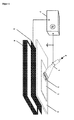
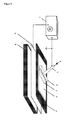
- Fig. 1 shows the basic structure of the device with a planar, with a dielectric or ferroelectric (4) covered high-voltage electrode (5) and formed as a grounded contact electrode, the gas nozzle (1) on a on the dielectric (4) resting workpiece ( 3) slidably produces a surface plasma (9).
- the gas supply (8) via the gas connection of the broad jet gas nozzle (1).
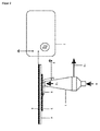
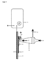
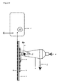
- the grounded contact electrode (2) can be used either as a sliding contact of electrically conductive elastomer, as in Fig. 2 shown as an electrically conductive role, as in Fig. 3 shown, or as a brush of electrically conductive bristles, as in Fig. 4 demonstrated to be performed.
- Fig. 5 shows the same structure as Fig.
- a metal tube with a narrow slot for the gas outlet simultaneously acts as a broad jet gas nozzle (1) and as a grounded contact electrode (2).
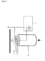
- Fig. 6 shows an arrangement for the treatment of hollow bodies made of plastic (3), in which an electrically conductive filling of the hollow body serves as a high voltage electrode and the hollow body simultaneously acts as a dielectric (4) of the high voltage electrode.
- Fig. 7 is the basic structure for internal treatment (dry cleaning, disinfection and / or coating) of bottles.
- Figure 8 shows an application example of an arrangement for the dry cleaning and disinfection of specially designed tables and wall coverings in hygienically sensitive areas, such as in operating theaters or in the field of food processing.
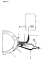
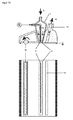
- Fig. 9 demonstrates the basic structure of a compact hand-held device for the treatment of complex-shaped plastic surfaces, in which the high-voltage electrode (5) covered with an insulator (4) is arranged in the gas nozzle (1). At the end of this high-voltage electrode, the electrically conductive, designed as a sieve grounded contact electrode (2) is arranged in the plane of the nozzle opening. In the Fig. 10 The arrangement shown is similarly constructed. This device is intended for the treatment of complex shaped metal surfaces.
- the metal surface itself serves as a conductive, grounded contact electrode
- a special contact electrode mounted on the nozzle can be dispensed with.
- the high-voltage electrode (5) surrounded by a dielectric (4) can also be arranged outside the gas nozzle.
- the in the Fig. 10 and 12 However, arrangements shown are not part of the claimed invention.
- Fig. 11 shows another embodiment of a compact handset, in which instead of a single insulator-covered high-voltage electrode, an array of a plurality of individual electrodes is used. In this way, surface discharges of larger surface area are generated, so that the necessary treatment times can be shortened accordingly.
- FIGS. 13 to 16 Further construction examples for compact handheld devices are in FIGS. 13 to 16 shown.
- this is a designed as a compact multi-channel plasma nozzle embodiment for the treatment of metal surfaces, in which the metallic workpiece acts as a grounded contact electrode and at Fig. 14 an arrangement of the same type for the treatment of plastic surfaces with a, arranged in the plane of the nozzle openings, metal gauze as a grounded contact electrode (2).
- the process gas flows through a perforated plate made of insulating material (6), in front of which the insulator-covered high voltage electrode (4/5) is arranged in a spiral shape.
- Fig. 15 puts it in a similar way as in Fig.
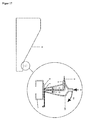
- Fig. 17 will the possibility of applying a compact handset, as it is in Fig. 9 is shown, for dry cleaning or disinfection of handrails (3) (for example on escalators) demonstrated.
- Fig. 18 shows two ways of arranging a second nozzle channel (15) for the extraction (16) of ozone produced by the discharge.
- These nozzle channels (15) can, as in Fig. 19 also be used for the precursor supply (17) for the coating treatment.
- Fig. 20 is one after the in Fig. 1 to Fig. 5 explained principle working, motor-driven table unit shown.
- a device for combined cleaning by means of a rotating brush (18), for dry cleaning and disinfection by means of plasma treatment by an arrangement as described in US Pat Fig. 9 is shown, and for the extraction (16) of dust and ozone via another nozzle (15) shown.
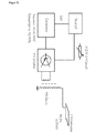
- Fig. 22 shows the schematic diagram of the power supply.
- Fig. 23 is a based on the working principle of the invention treatment unit for the external treatment of insulated wires to improve the wettability, as well as in Fig. 24 a similarly constructed treatment unit for dry cleaning and disinfection of the outer surface of catheters shown.
- the objects to be treated act as a high voltage electrode (5) covered with a dielectric (4)
- the electrically conductive grounded contact electrode (2) consists of two thin wires closely fitting the objects.
- a made of two, with hinges (19) connected, hinged, halves existing pipe of insulating material allows both the support and defined positioning of the objects, as well as the finely metered gas supply (8).
- Fig. 25 shows a specific embodiment of the in Fig. 16 illustrated arrangement.
- the gas nozzle has a flatter shape and, like the electrodes and the gas-permeable insulating layer in the plane of the gas outlet, is made of elastic materials.
- This arrangement makes it possible to conform the contact surface to different body surfaces and is thus in principle suitable for being placed on areas of the human body in close skin contact in the manner of an elastic cuff in order to be able to treat any diseased areas of the skin by the generated surface discharge.
Landscapes
- Engineering & Computer Science (AREA)
- Plasma & Fusion (AREA)
- Physics & Mathematics (AREA)
- Health & Medical Sciences (AREA)
- Chemical & Material Sciences (AREA)
- Analytical Chemistry (AREA)
- Life Sciences & Earth Sciences (AREA)
- Nuclear Medicine, Radiotherapy & Molecular Imaging (AREA)
- Animal Behavior & Ethology (AREA)
- Veterinary Medicine (AREA)
- Public Health (AREA)
- General Health & Medical Sciences (AREA)
- Surgery (AREA)
- Biomedical Technology (AREA)
- Medical Informatics (AREA)
- Organic Chemistry (AREA)
- Chemical Kinetics & Catalysis (AREA)
- Dermatology (AREA)
- Bioinformatics & Cheminformatics (AREA)
- Otolaryngology (AREA)
- Medicinal Chemistry (AREA)
- Pharmacology & Pharmacy (AREA)
- General Chemical & Material Sciences (AREA)
- Heart & Thoracic Surgery (AREA)
- Molecular Biology (AREA)
- Radiology & Medical Imaging (AREA)
- Apparatus For Disinfection Or Sterilisation (AREA)
- Cleaning In General (AREA)
- Plasma Technology (AREA)
- Physical Or Chemical Processes And Apparatus (AREA)
- Chemical Vapour Deposition (AREA)
- Cleaning And De-Greasing Of Metallic Materials By Chemical Methods (AREA)
- Medicines That Contain Protein Lipid Enzymes And Other Medicines (AREA)
- Details Of Rigid Or Semi-Rigid Containers (AREA)
Description
- Die Erfindung betrifft ein Verfahren und eine Reihe von Vorrichtungen zur trockenen Reinigung, Aktivierung, Beschichtung, Modifizierung und biologischen Dekontamination (Entkeimung, Desinfektion, Sterilisation) von Oberflächen mittels eines, durch eine so genannte Oberflächen-Barrierenentladung erzeugten, Atmosphärendruckplasmas.
- Zur Behandlung von Materialoberflächen mit dem Ziel, die Oberfläche zu reinigen (bzw. zu dekontaminieren), aktivieren, funktionalisieren bzw. beschichten, um sie für nachfolgende technologische Prozesse, wie beispielsweise Kleben, Drucken, Lackieren vorzubereiten bzw. um Arbeiten unter keimfreien Bedingungen durchführen zu können, werden bereits standardmäßig plasmatechnische Verfahren eingesetzt. In der Vergangenheit kamen dafür, insbesondere für komplexe Oberflächengeometrien, vorrangig Niederdruckplasmen in Betracht. Wegen der hohen Anlagenkosten für die dafür erforderlichen Vakuumapparaturen, der diskontinuierlichen Arbeitsweise sowie wegen der durch die Größe des verwendeten Rezipienten eingeschränkten geometrischen Abmessungen der zu behandelnden Werkstücke ist ein Einsatz von Niederdruck-Plasmaverfahren für großtechnische Anwendungen, insbesondere in der industriellen Fließfertigung nur bedingt möglich. Für die Integration plasmatechnologischer Verfahren der Oberflächenbehandlung in industriellen Fertigungsstrecken werden Atmosphärendruckplasmen genutzt. Plasmen dieser Art können beispielsweise durch Korona- oder Barrierenentladungen erzeugt werden. Sie können aber auch in Form von Normaldruck-Strahlplasmen verwendet werden, die auf der Grundlage von Korona-, Barrieren- oder Bogenentladungen durch die Realisierung geeigneter Prozessgasströmungen generiert werden.
- Verfahren und Vorrichtungen zur Oberflächenbehandlung, die auf der Nutzung derartiger Plasmen basieren, werden in zahlreichen Druckschriften beschrieben und teilweise auch bereits für unterschiedliche Anwendungen genutzt. Die in diesen Schriften beschriebenen technischen Lösungen sind aber mindestens mit einem oder mit mehreren der folgenden Nachteile verbunden:
- Es werden aufwendige, kostspielige Stromversorgungsgeräte benötigt.
- Durch einen hohen Energieverbrauch sowie teilweise auch durch hohen Gasverbrauch und erforderliche Kühlung entstehen relativ hohe Betriebskosten.
- Eine gleichmäßige Behandlung (insbesondere Beschichtung) des Materials ist durch die inhomogene Struktur der Plasmen erschwert.
- In vielen Fällen sind die Entladungen inhomogen und bestehen aus vielen kleinen, energiereichen Mikroentladungen, die zu lokalen Materialschäden führen können.
- Die Vorrichtungen sind nicht universell an beliebigen Werkstücken anwendbar. Entweder sind sie nur für die Behandlung von ebenen Materialien mit einer auf einige Millimeter begrenzten Materialstärke (wie beispielsweise Folien und Bahnmaterialien) geeignet oder nur mittels aufwändiger Positionierssysteme an Werkstücke mit komplexer Oberflächengeometrie adaptierbar.
- Die Vorrichtungen sind nicht als Handgeräte für den manuell geführten Betrieb nutzbar.
- Zum Stand der Technik gehören auch die nachfolgend aufgeführten Druckschriften. In
DE 195 32 412 A1 wird ein Verfahren zur Oberflächen-Vorbehandlung von Werkstücken mittels eine Plasmastrahls beschrieben, wobei der Plasmastrahl zunächst als Lichtbogen in einer Düse mit Elektroden erzeugt und durch eine verwirbelte Arbeitsgasströmung aus der Elektrodenanordnung heraus auf das zu behandelnde Werkstück übertragen wird. InDE 298 05 999 U1 wird eine Vorrichtung beschrieben, die mittels eines Rotationskopfes mit mindestens einer wie oben beschriebenen, exzentrisch angeordneten Plasmadüse einen parallel zur Rotationsachse gerichteten Plasmastrahl trägt, Oberflächen plasmabehandeln kann. InDE 10 2004 033 728 A1 wird ein Verfahren zum Bearbeiten und Verkleben von Werkstücken aus einem Metall oder einer Metalllegierung mit einer hydratisierten Oxid- und/oder Hydroxidschicht beschrieben, wobei die Reinigung, Aktivierung und Nachbehandlung mit einem atmosphärischen Plasmastrahl erfolgen.DE 199 27 557 A1 beschreibt ein Verfahren zur Vorbehandlung von zu schweißenden oder zu lötenden Werkstücken, wobei zwischen einer Elektrode und der zu behandelnden Oberfläche des Werkstücks eine Hochfrequenz-Bogenentladung erzeugt wird. Die hier beschriebenen Vorrichtung und Verfahren weisen wesentliche Unterschiede zu den später beschriebenen erfindungsgemäßen Verfahren und Vorrichtungen auf. Die Elektrodenanordnung ist stets so ausgeführt, dass sich die Elektroden an oder in unmittelbarer Nähe zum Werkstück befinden und das Plasma möglichst direkt an seinem Wirkungsort erzeugt wird. Die eingesetzte Gasströmung hat nicht die Funktion, das Plasma aus der Elektrodenanordnung heraus an das Werkstück zu tragen oder die Elektrodenanordnung zu kühlen, wie im Falle der Plasmastrahlen oder Plasmajets, sondern dient lediglich der lokalen Intensivierung des Plasmas an seinem Wirkungsort und der Steuerung seiner Parameter (u.a. Art und Zustand der angeregten Spezies). Durch die spezielle Elektrodenanordnung wird der Gasverbrauch sehr gering gehalten und die zum Plasmabetrieb erforderliche Zündspannung minimiert. So können die benötigten Stromversorgungsgeräte sehr klein, einfach und kompakt gestaltet werden. - In den Druckschriften
DE 43 25 939 C1 ,WO 2004/053185 A1 undDE 38 27 629 A1 werden Verfahren und Vorrichtungen zur Oberflächenvorbehandlung beschrieben, die auf dem Prinzip der sog. Volumen-Barrierenentladung (auch stille Entladung, dielektrisch behinderte Entladung oder Korona-Behandlung) basieren. Die Erfahrung zeigt, dass die Anwendbarkeit sog. Korona-Behandlungsanlagen nur für die Behandlung von ebenen Materialien mit einigen Millimetern Materialstärke (beispielsweise Folien und Bahnmaterialien) praktikabel ist. InWO 2004/053185 A1 wird eine mit einem Dielektrikum bedeckte Elektrode verwendet, um ein Plasma in einer Reaktivgaströmung zu erzeugen um Metalloberflächen, die gleichzeitig als Gegenelektrode fungieren, mittels der Plasmabehandlung zu konservieren.DE 38 27 629 A1 stellt ein Verfahren Oberflächenvorbehandlung von elektrisch leitenden Formmaterialien, wie Metallfolienbahnen oder Kunststofffolien, in deren Polymermatrix elektrisch leitfähige Partikel eingelagert sind, vor. Die Entladung wird zwischen von dielektrischem Material ummantelten Entladungselektroden und den Metallkern einer Walze, die als geerdete Gegenelektrode dient erzeugt, wobei über die Walze die zu behandelnde Folienbahn transportiert wird. Zusätzlich kann das Arbeitsgas mittels einer Zerstäubereinrichtung mit einem schwebfähigen Aerosol versehen werden. In beiden Fällen bilden die Gegenelektrode und die von dielektrischem Material ummantelten Entladungselektroden einen Entladungsspalt, so dass ein sog. kaltes Plasma im Volumen erzeugt wird. In zwei der oben genannten Patenschriften (DE 43 25 939 C1 ,WO 2004/053185 A1 ) werden auch sog. indirekte Koronabehadlungen beschrieben. Die inDE 43 25 939 C1 vorgestellte Koronadüse dient der indirekte Plasmabehandlung von bahnförmigen oder profilierten Materialien und weist mindestens zwei Hochspannungselektroden auf, zwischen denen ein oszillierend oder umlaufend geführter Luftstrom austritt. InWO 2004/053185 A1 wird eine sog. indirekte Barrierenentladung zur Konservierung von Metalloberflächen beschrieben. In beiden Fällen hat der Gasstrom, ähnlich wie bei einem Plasmastrahl oder Plasmajet die Aufgabe, die Entladung aus dem Raum zwischen den beiden Elektroden an das zu behandelnde Werkstück heraus zutreiben. Der Gasstrom wirkt somit auf die Form und flächige Gestalt des Plasmas ein. Es werden drei Ausführungen für die rotierende bzw. umlaufende Führung des Luftstroms beschrieben. - In der Patenschrift
DE 102 19 197 C1 werden Verfahren und Vorrichtung zur Behandlung der Oberflächen eines Metalldrahts, insbesondere als Beschichtungsvorbehandlung beschrieben. Dabei wird der Metalldrahts an eine Elektrode, die zu dem Metalldraht hin mit einer dielektrischen Abschirmung versehen ist, eine Wechselhochspannung angelegt, um im Gasraum über der Oberfläche des Metalldrahts eine Volumen-Barrierenentladung hervorzurufen.
In der OffenlegungsschriftDE 10 2005 001 264 A1 wird eine Ingredienzanalysevorrichtung und ein Ingredienzanalyseverfahren beschrieben, bei dem Hochfrequenzenergie von einer Energiequelle zugeführt wird, während Heliumgas zu einer, Atmosphärendruck-Plasmaquelle geführt wird, die in der Nähe einer zu analysierenden Substanz angeordnet ist, wobei Plasma erzeugt wird, und die zu analysierende Substanz dem Plasma ausgesetzt ist und Licht emittiert wird. Dabei findet die Plasmaerzeugung nicht auf der Oberfläche, sondern über der Oberfläche statt. Es handelt sich um eine Volumen-Entladung, nicht um eine Oberflächen-Entladung. - Aufgabe der Erfindung ist es, eine Vorrichtung und ein Verfahren zur plasmagestützten Oberflächenbehandlung von Werkstoffen bereitzustellen, die diese Mängel nicht aufweisen.
- Die Aufgabe wird gemäß den Merkmalen der Patentansprüche 1 und 9 gelöst. Erfindungsgemäß wird eine Vorrichtung und ein Verfahren zur Behandlung von Oberflächen erstmals bereitgestellt, die dadurch gekennzeichnet sind, dass auf der Oberfläche des zu behandelnden Materials bzw. in deren unmittelbarer Nähe eine Oberflächen-Barrierenentladung durch den Kontakt einer dielektrikumbedeckten Hochspannungselektrode mit einer geerdeten, elektrisch leitenden Kontaktelektrode, die in einer, aus einer speziell angepassten Gasdüse strömenden, lokal auf die Kontaktstelle gerichteten, schwachen Prozessgasatmosphäre betrieben wird. Der gerichtete, schwache Prozessgasstrom spielt dabei für die Effizienz der Vorrichtung zur Oberflächenbehandlung, und damit für die Gesamtfunktion, eine wesentliche Rolle. Verwendet man dafür ein Edelgas, wie beispielsweise Argon, so wird die Zündspannung der Oberflächenentladung im Vergleich zu einem Betrieb in Luft deutlich herabgesetzt und die Leuchterscheinung des Plasmas auf der Oberfläche des Isoliermaterials (Dielektrikums) wird nicht nur heller, sondern bedeckt auch eine größere Fläche des Materials. Dieses visuelle Erscheinungsbild ist verbunden mit einem deutlich stärkeren Effekt der Oberflächenbehandlung durch das Plasma, wie beispielsweise durch Kontaktwinkelmessungen und geeignete Methoden der Oberflächendiagnostik nachgewiesen werden kann. Dabei genügt ein sehr geringer Gasfluss, um diesen Effekt zu erzielen. So ist es beispielsweise möglich, mit einer geerdeten Kontaktelektrode von 20 cm Länge und einer daneben angeordneten Breitstrahldüse gleicher Länge, aus der durch einen ca. 0,2 - 0,3 mm schmalen Schlitz das Gas auf die Kontaktstelle strömt, bei einem Gasfluss von 0,5 - 1 slm (slm - Standart Liter pro Minute) Ar bereits einen deutlichen Effekt zu erreichen. Die Vorteile der hier benutzten Oberflächen-Barrierenentladungen gegenüber sogenannten Volumen-Barrierenentladungen, die vor allem darin bestehen, dass sowohl die benötigten Betriebsspannungen, als auch die umgesetzte elektrische Leistung geringer sind und die Plasmen eine homogenere Struktur haben, werden durch die fein dosierte Zuführung dieser Gasströmung noch wesentlich stärker ausgeprägt, so dass sich auch die Anforderungen an die Stromversorgungsgeräte deutlich reduzieren lassen.
- Als ein wichtiger Bestandteil der Vorrichtung kann das Stromversorgungsgerät daher mit minimalen geometrischen Abmessungen dimensioniert werden, so dass es beispielsweise in einer als Handgerät ausgeführten Vorrichtung integriert werden kann. Dabei erfolgt die Spannungsversorgung der Hochspannungselektrode durch das schnelle Schalten eines Hochspannungstransformators. Das hierfür erforderliche Schaltsignal mit einer Frequenz von 10 kHz bis 40 kHz und einem variablen Tastverhältnis von 10 bis 90% wird von einem Rechteckgenerator geliefert. Die eigentliche Schaltstufe besteht aus einem Leistungs-MOSFET mit davor geschaltetem Treiberschaltkreis. Die Hochspannungsamplitude ist bis zu einem maximalen Wert von 7 kVeff regelbar.
- Überraschenderweise hat sich herausgestellt, das die erfindungsgemäße Vorrichtung ohne Kühlung, mit einem geringen Energie- und Gasverbrauch und mit einem einfachen, kostengünstigen Stromversorgungsgerät betrieben werden kann, eine gleichmäßige, effiziente Behandlung ohne Schädigung des zu behandelnden Materials gestattet, auch für die Behandlung von Werkstücken mit komplexer Oberflächengeometrie geeignet ist und die Möglichkeit bietet, als Handgerät für den manuell geführten Betrieb genutzt zu werden. Die Eigenschaften des Gerätes zeigen Anwendungsgebiete auf, die über den Einsatz zur Oberflächenbehandlung von Werkstücken hinausgehen. So ist beispielsweise bei entsprechender Ausführung eine Behandlung von biologischen Gewebe möglich.
- Abhängig von Art, Form und Größe der zu behandelnden Materialien, sowie von dem gewünschten Behandlungseffekt können Aufbau und Anordnung der dielektrikumbedeckten Hochspannungselektrode, der geerdeten Kontaktelektrode und der Gasdüse in unterschiedlicher Weise gestaltet beziehungsweise kombiniert werden. So kann beispielsweise in einem Grundaufbau zur Behandlung von Kunststoffen in Gestalt ebener Folien-, Bahn- bzw. Plattenmaterialien das zu behandelnde Material auf der Isolierstoffschicht einer ebenen, dielektrikumbedeckten Hochspannungselektrode aufgelegt werden. Über die zu behandelnde Kunststoffoberfläche wird die elektrisch leitende, geerdete, mit einer Breitstrahl-Gasdüse gekoppelte Kontaktelektrode geführt. Die Kontaktelektrode kann dabei sowohl als Gleitkontakt, als auch als Rolle oder Pinsel ausgeführt werden und entweder aus Metall oder andere elektrisch leitenden Materialien (zum Beispiel aus elektrisch leitenden Elastomeren) gefertigt sein. Die als schmaler Schlitz ausgebildete Austrittsöffnung der Breitstrahl-Gasdüse ist unmittelbar neben dem Kontaktstreifen der Kontaktelektrode angeordnet. Wird an die Hochspannungselektrode eine Spannung ausreichender Höhe (abhängig von Materialart und -dicke) angelegt, so setzt am Kontaktstreifen auf der Kunststoffoberfläche eine Oberflächenentladung an. Durch den auf den Kontaktstreifen auftreffenden schwachen Gasstrom aus dem Schlitz der Breitstrahldüse wird die Ausdehnung dieser Entladung vergrößert und deren Intensität wesentlich erhöht.
- Die Elektrodenanordnung ist stets so ausgeführt, dass sich die Elektroden an oder in unmittelbarer Nähe zum Werkstück befinden und das Plasma möglichst direkt an seinem Wirkungsort erzeugt wird. Die eingesetzte Gasströmung hat nicht die Funktion, das Plasma aus der Elektrodenanordnung heraus an das Werkstück zu tragen oder die Elektrodenanordnung zu kühlen, wie im Falle der Plasmastrahlen oder Plasmajets, sondern dient lediglich der lokalen Intensivierung des Plasmas an seinem Wirkungsort und der Steuerung seiner Parameter (u.a. Art und Zustand der angeregten Spezies). Durch die spezielle Elektrodenanordnung wird der Gasverbrauch sehr gering gehalten und die zum Plasmabetrieb erforderliche Zündspannung minimiert. So können die benötigten Stromversorgungsgeräte sehr klein, einfach und kompakt gestaltet werden.
- Außerdem ist eine besonders einfache Handhabung möglich, denn zum einen muss kein bestimmter Abstand zwischen Plasmaquelle und zu behandelnder Oberfläche eingehalten und zum anderen muss dieser nicht mittels aufwändiger Positionierssysteme sichergestellt werden, sondern die Entladung wird in Form eines mobilen Kontaktplasmas einfach über die zu behandelnde Oberfläche geführt. Solche Vorrichtungen sind universell an beliebigen Werkstücken anwendbar. Außerdem gelingt es durch die prinzipiellen Unterschiede im Aufbau stets ein sog. kaltes Plasma zu erzeugen, d.h. die Gastemperatur wird erfahrungsgemäß nur leicht erhöht, im Gegensatz zu den im Stand der Technik beschriebenen Plasmastrahlen, die erfahrungsgemäß bedingt durch die initiale Erzeugung eines Lichtbogens einen nicht unerhebliche Teil der eingekoppelten elektrischen Energie in Wärme umwandeln.
- In der hier beschriebenen Erfindung befinden sich - im Unterschied zu den im Stand der Technik genannten Vorrichtungen und Verfahren - die von dielektrischem Material ummantelten Entladungselektroden auf oder am Werkstück, welches die Gegenelektrode darstellt, so dass eine sog. Oberflächen-Barrierenentladung direkt auf der zu behandelnden Oberfläche erzeugt wird. Somit kann die Entladung als mobiles Kontaktplasma einfach über die zu behandelnde Oberfläche geführt werden (Handgerät für manuell geführten Betrieb), wobei die Plasmaausbildung auf der Oberfläche durch eine zusätzliche, aber nur geringe oder seichte Gasströmung (d.h. z.B. keine rotierende bzw. umlaufende Führung des Luftstroms), lediglich noch intensiviert wird. Da die Gasströmung das Plasma nicht mehr an die Oberfläche transportieren muss, ist der Gasverbrauch relativ gering. Diese Unterschiede ermöglichen auch für die Behandlung von sehr komplexen Werkstücken eine sehr einfache Handhabung, die zusätzlich dadurch unterstützt wird, dass aufgrund der Plasmaintensivierung durch die seichte Prozessgasströmung die erforderlichen Stromversorgungsgeräte besonders klein, einfach und kompakt gestaltet werden können.
- Im Unterschied zu
DE 102 19 197 C1 wird mit der hier beschriebenen Erfindung hingegen ein Verfahren für die äußere Behandlung von isolierten Drähten zur Verbesserung der Benetzbarkeit vorgestellt. Dabei werden die zu behandelnden Drähte als bereits mit einem Dielektrikum ummantelte Hochspannungselektroden genutzt und mittels einer eng an dem zu behandelnden isolierten Draht anliegenden, elektrisch leitenden, geerdeten Kontaktelektrode, angeordnet in einem Rohr aus Isoliermaterial, eine Oberflächen-Barrierenentladung auf der Drahtisolationsoberfläche erzeugt. - Entsprechend dem hier dargestellten Grundaufbau dieser Ausführungsform kann die Vorrichtung als Tischgerät für die Behandlung von ebenen Materialien mit einer eingeschränkten Flächenausdehnung (z.B. in den Formaten DIN A6 bis DIN A0) ausgelegt werden, bei dem die Abtastung der Fläche, ähnlich wie bei einem optischen Scanner, über einen Motorantrieb erfolgt. Geräte dieser Art sind beispielsweise vorteilhaft einsetzbar in Werbeateliers bzw. Druckereien, um durch die Plasmabehandlung von Folien oder Schildern aus Kunststoff eine Verbesserung der Haftung von Klebefolien oder Druckfarben auf diesen Materialien zu erreichen.
- Als eine weitere Anwendung bietet diese Grundform der Vorrichtung die Möglichkeit, für große Flächen im Klinikbereich (zum Beispiel in Operationssälen) oder im Lebensmittelbereich, wie beispielsweise für speziell präparierte Tisch- bzw. Wandbeläge mittels dieser Plasmabehandlung eine trockene Reinigung beziehungsweise Desinfektion (Entkeimung, biologische Dekontamination) zu realisieren. Dazu sind die Tisch- bzw. Wandbeläge so zu gestalten, dass sie als dielektrikumbedeckte Hochspannungselektrode genutzt werden können.
- Eine weitere Ausführungsform des oben dargestellten Grundaufbaus der Vorrichtung erhält man, wenn anstelle einer ebenen eine als rotierende Walze ausgestaltete, dielektrikumbedeckte Hochspannungselektrode verwendet wird. Mit einer derartigen Vorrichtung lassen sich beispielsweise vorteilhaft Bahnmaterialien oder längere Platten behandeln, die mittels einer geeigneten Vorschubeinrichtung zwischen der rotierenden Hochspannungselektrode und der auf der Oberfläche des Materials gleitenden oder rollenden, als Kontaktelektrode gestalteten Breitstrahl-Gasdüse hindurch bewegt werden.
- In einer weiteren Ausführungsform dieser Grundform der Vorrichtung können Hohlkörper aus Kunststoff behandelt werden, indem die Hohlkörper mit einer leitfähigen Masse (beispielsweise mit Stahlwolle, leitfähigem plastischen Material oder mit elektrisch leitender Flüssigkeit) gefüllt werden, die mit der Hochspannung verbunden wird und so gemeinsam mit dem Kunststoff-Hohlkörper als dielektrikumbedeckte Hochspannungselektrode wirkt. Auf der Oberfläche des Hohlkörpers wird durch die manuell darüber geführte Gasdüse mit geerdeter Kontaktelektrode die intensivierte Oberflächenentladung erzeugt.
- Eine weitere Ausführungsform dieser Vorrichtung ermöglicht die trockene Reinigung beziehungsweise Entkeimung oder Beschichtung der inneren Oberfläche von Flaschen. Dazu wird die Flasche passgenau von zwei Hälften einer elektrisch leitenden Form umschlossen, die auf Hochspannungspotential gelegt werden. Zusammen mit der Flaschenwand wirkt diese Form als dielektrikumbedeckte Hochspannungselektrode. Im Inneren der Flasche wird eine Flaschenbürste aus elektrisch leitendem Material angeordnet, deren Borsten eng an der inneren Oberfläche der Flasche anliegen und als geerdete Kontaktelektrode wirken. Die Gaszuführung erfolgt dabei über die als Rohr ausgeführte Halterung der Flaschenbürste. Eine Beschichtung der Innenwand der Flasche wird durch die Zumischung eines geeigneten Precursors zum Prozessgas erreicht. Wird als Precursor eine siliziumorganische Verbindung (zum Beispiel Hexamethyldisiloxan HMDSO oder Tetraethylorthosilicat TEOS) verwendet, so können sowohl im Fall ebener Anordnungen als auch im Fall der Innenbehandlung von Flaschen SiOx.-Schichten auf den Oberflächen erzeugt werden.
- In weiteren Ausführungsformen der Vorrichtung werden eine oder mehrere dielektrikumbedeckte Hochspannungselektroden in einem Handgerät in der Weise integriert, dass die Kontaktflächen zwischen den integrierten, dielektrikumbedeckten Hochspannungselektroden und der geerdeten Kontaktelektrode in der Ebene des Gasaustritts aus der Gasdüse angeordnet sind, so dass in diesem Bereich auf der Oberfläche des Dielektrikums der Hochspannungselektrode eine intensivierte Oberflächenentladung erzeugt wird.
- In weiteren Ausführungsformen der Vorrichtung können, wie durch die Zeichnungen zu den Ausführungsbeispielen näher erläutert wird, Katheter und Kabel außen behandelt werden. In ähnlichen Anordnungen können auch nach dem hier dargestellten Arbeitsprinzip Behandlungen und Beschichtungen der inneren Oberfläche von Rohren und Schläuchen realisiert werden.
-
- Das Verfahren ist sehr vielseitig einsetzbar, ist auch für die Behandlung komplexer Oberflächengeometrien geeignet und bietet die Möglichkeit, sowohl in Form eines kostengünstigen Handgerätes, als auch in der Gestalt maschinell gesteuerter Anlagen genutzt zu werden.
- Aufgrund des geringen Energie- und Gasverbrauchs, sowie der geringen Investitionskosten für die Stromversorgungsgeräte und Behandlungseinheiten, bietet das Verfahren eine sehr kostengünstige Lösung für viele Anwendungen.
- Das Verfahren gestattet eine homogene Plasmabehandlung bzw. -beschichtung von Oberflächen, wobei durch eine geeignete Wahl der Prozessparameter Materialschäden durch elektrische Durchschläge oder thermische Belastungen ausgeschlossen werden können.
- Das Verfahren gestattet eine Plasmabehandlung von biologischem Gewebe, wobei durch geeignete Wahl der Prozessparameter elektrische Durchschläge oder thermische Belastungen ausgeschlossen werden können.
- Die Erfindung wird nachfolgend anhand von Ausführungsbeispielen näher erläutert, ohne sie auf diese Beispiele zu beschränken.
- Mit den nachfolgend in verschiedenen Zeichnungen dargestellten Ausführungsbeispielen werden die Erfindung und deren Anwendungsmöglichkeiten detailliert erläutert. Für die Kennzeichnung der einzelnen Elemente des Aufbaus der Vorrichtungen werden folgende Bezugszeichen verwendet:
-
1 Gasdüse 2 geerdete Kontaktelektrode 3 Werkstück 4 Isolator (Dielektrikum oder Ferroelektrikum) 5 Hochspannungselektrode 6 Isolation 7 Hochspannungsquelle 8 Gaszufuhr 9 Oberflächenplasma 10 Gehäuse mit Hochspannungsversorgung 11 Motor mit Magnetkupplung 12 Gasaustritt 13 Bewegungsrichtung 14 Fügekante 15 zweiter Düsenkanal 16 Absaugung 17 Precursor-Zufuhr 18 rotierende Bürste 19 Scharnier 20 Griffstück mit Steckeranschluss -
Fig. 1 zeigt den prinzipiellen Aufbau der Vorrichtung mit einer ebenen, mit einem Dielektrikum- oder Ferroelektrikum (4) bedeckten Hochspannungselektrode (5) sowie mit einer, als geerdete Kontaktelektrode ausgebildeten, Gasdüse (1), die auf einem auf dem Dielektrikum (4) aufliegenden Werkstück (3) gleitend ein Oberflächenplasma (9) erzeugt. Die Gaszufuhr (8) erfolgt über den Gasanschluss der Breitstrahl-Gasdüse (1). Die geerdete Kontaktelektrode (2) kann dabei entweder als Gleitkontakt aus elektrisch leitendem Elastomer, wie inFig. 2 dargestellt, als elektrisch leitende Rolle, wie inFig. 3 gezeigt, oder als Pinsel aus elektrisch leitenden Borsten, wie inFig. 4 demonstriert, ausgeführt werden.Fig. 5 zeigt den gleichen Aufbau wieFig. 1 , bei dem jedoch ein Metallrohr mit einem schmalen Schlitz für den Gasaustritt gleichzeitig als Breitstrahl-Gasdüse (1) und als geerdete Kontaktelektrode (2) fungiert.Fig. 6 zeigt eine Anordnung zur Behandlung von Hohlkörpern aus Kunststoff (3), bei der eine elektrisch leitende Füllung des Hohlkörpers als Hochspannungselektrode dient und der Hohlkörper gleichzeitig als Dielektrikum (4) der Hochspannungselektrode wirkt. InFig. 7 ist der prinzipielle Aufbau zur Innenbehandlung (trockene Reinigung, Desinfektion und/oder Beschichtung) von Flaschen dargestellt.Fig.8 zeigt als Anwendungsbeispiel eine Anordnung zur trockenen Reinigung und Desinfektion von speziell konstruierten Tischen und Wandbelägen in hygienisch sensiblen Bereichen, wie zum Beispiel in Operationssälen bzw. im Bereich der Lebensmittelverarbeitung. Die Beläge der Tische und Wände sind dafür so zu gestalten, dass sie als mit einem Isolator (4) bedeckte Hochspannungselektrode (5) geschaltet werden können.Fig. 9 demonstriert den prinzipiellen Aufbau eines kompakten Handgerätes zur Behandlung komplex geformter Kunststoff-Oberflächen, bei dem die mit einem Isolator (4) bedeckte Hochspannungselektrode (5) in der Gasdüse (1) angeordnet ist. Am Ende dieser Hochspannungselektrode ist in der Ebene der Düsenöffnung die elektrisch leitende, als Sieb gestaltete, geerdete Kontaktelektrode (2) angeordnet. Die inFig. 10 gezeigte Anordnung ist ähnlich konstruiert. Diese Vorrichtung ist zur Behandlung von komplex geformten Metalloberflächen vorgesehen. Da in diesem Fall die Metalloberfläche selbst als leitende, geerdete Kontaktelektrode dient, kann auf eine, an der Düse montierte, spezielle Kontaktelektrode verzichtet werden. Wie inFig. 12 dargestellt, kann in einer ähnlichen Vorrichtung die mit einem Dielektrikum (4) umgebene Hochspannungselektrode (5) auch außerhalb der Gasdüse angeordnet werden. Die in denFig. 10 und12 gezeigten Anordnungen sind aber nicht Teil der beanspruchten Erfindung. -
Fig. 11 zeigt eine weitere Ausführungsform eines kompakten Handgerätes, bei der anstelle einer einzelnen isolatorbedeckten Hochspannungselektrode ein Array aus mehreren Einzelelektroden verwendet wird. Auf diese Weise werden Oberflächenentladungen größerer Flächenausdehnung erzeugt, so dass sich die notwendigen Behandlungszeiten entsprechend verkürzen lassen. - Weitere Konstruktionsbeispiele für kompakte Handgeräte sind in
Fig. 13 bis Fig. 16 dargestellt. Bei der Anordnung inFig. 13 handelt es sich dabei um eine als kompakte Mehrkanal-Plasmadüse gestaltete Ausführungsform zur Behandlung von Metalloberflächen, bei der das metallische Werkstück als geerdete Kontaktelektrode fungiert und beiFig. 14 um eine gleich geartete Anordnung für die Behandlung von Kunststoff-Oberflächen mit einer, in der Ebene der Düsenöffnungen angeordneten, Metall-Gaze als geerdete Kontaktelektrode (2). Bei den inFig. 15 undFig. 16 dargestellten Lösungen strömt das Prozessgas durch eine Lochplatte aus Isoliermaterial (6), vor der spiralförmig die isolatorbedeckte Hochspannungselektrode (4/5) angeordnet ist.Fig. 15 stellt dabei, in ähnlicher Weise, wie inFig. 13 , den Fall für die Behandlung von Metall-Oberflächen (als geerdete Kontaktelektrode wirkend) undFig. 16 , ähnlich wie inFig. 14 , den Fall für die Behandlung von Kunststoff-Oberflächen (Metall-Gaze als geerdete Kontaktelektrode) dar. Die in denAbb. 13 und15 gezeigten Anordnungen sind aber nicht Teil der beanspruchten Erfindung. - In
Fig. 17 wird die Möglichkeit der Anwendung eines kompakten Handgerätes, wie es inFig. 9 dargestellt ist, zur trockenen Reinigung beziehungsweise Desinfektion von Handläufen (3) (beispielsweise bei Rolltreppen) demonstriert. -
Fig. 18 zeigt zwei Möglichkeiten der Anordnung eines zweiten Düsenkanals (15) zur Absaugung (16) von, durch die Entladung produziertem, Ozon. Diese Düsenkanäle (15) können, wie inFig. 19 dargestellt, ebenso für die Precursor-Zufuhr (17) für die beschichtende Behandlung verwendet werden. - In
Fig. 20 ist ein nach dem inFig. 1 bis Fig. 5 erläuterten Prinzip arbeitendes, motorgesteuertes Tischgerät dargestellt. Als ein weiteres Anwendungsbeispiel ist inFig. 21 eine Vorrichtung zur kombinierten Reinigung mittels einer rotierenden Bürste (18), zur trockenen Reinigung und Desinfektion mittels Plasmabehandlung durch eine Anordnung, wie sie inFig. 9 dargestellt ist, sowie zur Absaugung (16) von Staub und Ozon über eine weitere Düse (15) dargestellt. -
Fig. 22 zeigt das Prinzipschaltbild der Spannungsversorgung. - In
Fig. 23 wird eine auf dem Arbeitsprinzip der Erfindung basierende Behandlungseinheit für die äußere Behandlung von isolierten Drähten zur Verbesserung der Benetzbarkeit, sowie inFig. 24 eine ähnlich aufgebaute Behandlungseinheit zur trockenen Reinigung und Entkeimung der äußeren Oberfläche von Kathetern dargestellt. In beiden Fällen wirken die zu behandelnden Objekte als eine, mit einem Dielektrikum (4) bedeckte, Hochspannungselektrode (5) und die elektrisch leitende, geerdete Kontaktelektrode (2) besteht aus zwei, eng an den Objekten anliegenden, dünnen Drähten. Ein aus zwei, mit Scharnieren (19) verbundenen, aufklappbaren, Hälften bestehendes Rohr aus Isoliermaterial ermöglicht sowohl die Halterung und definierte Positionierung der Objekte, als auch die fein dosierte Gaszufuhr (8). -
Fig. 25 zeigt eine spezielle Ausführungsform der inFig. 16 dargestellten Anordnung. In diesem Fall hat die Gasdüse eine flachere Form und ist, ebenso wie die Elektroden und die gasdurchlässige Isolierschicht in der Ebene des Gasaustritts aus elastischen Materialien hergestellt. Diese Anordnung gestattet, die Kontaktfläche an verschiedene Körperoberflächen anzuschmiegen und ist damit prinzipiell geeignet, in engem Hautkontakt in der Art einer elastischen Manschette auf Bereiche des menschlichen Körpers aufgelegt zu werden, um damit gegebenenfalls erkrankte Hautpartien durch die erzeugte Oberflächenentladung behandeln zu können.
Claims (16)
- Vorrichtung zur trockenen Reinigung, Aktivierung, Beschichtung, Modifikation und biologischen Dekontamination einer Oberfläche (3) mittels eines, durch eine Oberflächen-Barrierenentladung in einer definierten, strömenden Gasatmosphäre erzeugten Atmosphärendruckplasmas, umfassend eine mit einem Dielektrikum oder Ferroelektrikum (4) bedeckte Hochspannungselektrode (5) und eine elektrisch leitende, geerdete Kontaktelektrode (2), die dazu ausgelegt ist, im Betrieb eine Kontaktstelle mit der mit einem Dielektrikum oder Ferroelektrikum bedeckten Hochspannungselektrode aufzuweisen, weiter umfassend eine Hochspannunsversorgung (7), eine Gaszufuhr (8) und eine Gasdüse (1) mit einer Gasaustrittsöffnung (12), dadurch gekennzeichnet, dassa) die Gasdüse (1) in die Kontaktelektrode (2) integriert ist oderb) die Gasdüse (1) selbst als geerdete Kontaktelektrode (2) fungiert, und weiter dadurch gekennzeichnet, dass die Gasaustrittsöffnung (12) so konstruiert ist, dass im Betrieb ein austretender Gasstrom auf die Kontaktstelle zwischen der mit einem Dielektrikum bedeckten Hochspannungselektrode (5) und der geerdeten Kontaktelektrode (2) gerichtet ist.
- Vorrichtung nach Anspruch 1, dadurch gekennzeichnet, dass sie zusätzlich mindestens eines der folgenden Elemente enthält: Isolation (6), ein Gehäuse für die Hochspannungsversorgung (10), einen Motor, vorzugsweise mit Magnetkupplung (11), Fügekante (14), zweiter Düsenkanal (15), Absaugung (16), Precursor-Zufuhr (17), Scharnier (19) oder Griffstück mit Steckeranschluss (20).
- Vorrichtung nach Anspruch 1 oder 2, dadurch gekennzeichnet, dass als Gasdüse (1) eine Breitstrahldüse fungiert, deren Schlitz vorzugsweise 0,2 - 0,3 mm beträgt.
- Vorrichtung nach einem der Ansprüche 1 bis 3 dadurch gekennzeichnet, dass als Spannungsquelle (7) ein Handgerät dient.
- Vorrichtung nach einem der Ansprüche 1 bis 4, dadurch gekennzeichnet, dass die elektrisch leitende geerdete Kontaktelektrode (2)a) als Gleitkontakt oder als kleine Walze, Rolle, Bürste oder Pinsel ausgeführt ist und / oderb) aus Metall oder anderen elektrisch leitenden Materialien, vorzugsweise elektrisch leitenden Elastomeren, besteht.
- Vorrichtung nach einem der Ansprüche 1 bis 5, dadurch gekennzeichnet, dassa) die zu behandelnde Oberfläche (3) als dielektrikumbedeckte Hochspannungselektrode (5) genutzt wird oderb) die dielektrikumbedeckte Hochspannungselektrode (5) als ebene Form oder als rotierende Walze ausgestaltet ist oderc) die Oberfläche (3) mit einer elektrisch leitenden Form umschlossen ist und diese Form die dielektrikumbedeckte Hochspannungselektrode (5) bildet.
- Vorrichtung nach einem der Ansprüche 1 bis 6, dadurch gekennzeichnet, dass sie ein kompaktes Handgerät darstellt, in dem die eine oder mehrere dielektrikum-bedeckte Hochspannungselektroden gemeinsam mit einer aus Metall-Gaze oder einem gelochten Blech gebildeten, geerdeten Kontaktelektrode in dem Handgerät integriert sind und in der Ebene des Gasaustritts aus der Gasdüse angeordnet sind, so dass in diesem Bereich auf der Oberfläche des Dielektrikums der Hochspannungselektroden eine intensivierte Oberflächenentladung erzeugt wird.
- Tischgerät für die Behandlung von ebenen Materialien mit einer eingeschränkten Flächenausdehnung, das die Vorrichtung gemäß einem der Ansprüche 1 bis 7 enthält und vorzugsweise dazu ausgelegt ist, dass im Betrieb eine Abtastung der Fläche, ähnlich wie bei einem optischen Scanner, über einen Motorantrieb erfolgt.
- Verfahren zur trockenen Reinigung, Aktivierung, Beschichtung und biologischen Dekontamination einer Oberfläche mittels der Vorrichtung gemäß einem der Ansprüche 1 bis 8, gekennzeichnet durch folgende Schritte:a) ein zu behandelndes Material (3) befindet sich entweder zwischen der mit einem Dielektrikum oder Ferroelektrikum (4) bedeckten Hochspannungselektrode (5) und der geerdeten Kontaktelektrode (2) oder an deren Kontaktstelleb) ein Prozessgasstrom wird aus der Gasdüse (1) auf die Kontaktstelle der geerdeten Kontaktelektrode (2) gerichtetc) gleichzeitig oder unmittelbar danach wird eine Spannung an die Hochspannungselektrode (5) angelegt undd) die Kontaktelektrode (2) mit der Gasdüse (1) und das zu behandelnde Material (3) werden relativ zueinander bewegt,wobei auf der Oberfläche des zu behandelnden Materials (3), an der sich die Kontaktelektrode (2) mit der Gasdüse (1) befindet, in der Prozessgasströmung eine Oberflächen-Barrierenentladung erzeugt wird.
- Verfahren nach Anspruch 9, dadurch gekennzeichnet, dass als Prozessgas ein Edelgas, vorzugsweise Argon, in reiner Form oder als Gemisch mit anderen Gasen, eingesetzt wird.
- Verfahren nach Anspruch 9 oder 10, dadurch gekennzeichnet, dassa) das zu behandelnde Material (3) auf einer Isolierstoffschicht der ebenen, dielektrikum- oder ferroelektrikumbedeckten Hochspannungselektrode (5) aufgelegt wird und die elektrisch leitende, geerdete, mit einer Breitstrahl-Gasdüse (1) gekoppelte Kontaktelektrode (2) gleitend über die zu behandelnde Kunststoffoberfläche geführt wird und / oderb) für die Behandlung von ebenen Materialien mit einer eingeschränkten Flächenausdehnung, z.B. in den Formaten DIN A6 bis DIN AO, bei der die Abtastung der Fläche, ähnlich wie bei einem optischen Scanner, über einen Motorantrieb erfolgt und / oderc) zur Behandlung von längeren Bahnmaterialien oder Platten, bei der anstelle einer ebenen eine als rotierende Walze ausgestaltete, dielektrikum- oder ferroelektrikumbedeckte Hochspannungselektrode verwendet wird und mittels einer geeigneten Vorschubeinrichtung das zu behandelnde Material zwischen der rotierenden Hochspannungselektrode und der auf der Oberfläche des Materials gleitenden oder rollenden, als geerdete Kontaktelektrode gestalteten, Breitstrahl-Gasdüse hindurch bewegt wird.
- Verfahren nach Anspruch 11, dadurch gekennzeichnet, dassa) Hohlkörper aus Kunststoff behandelt werden, indem die Hohlkörper mit einer leitfähigen Masse, beispielsweise mit Stahlwolle, leitfähigem plastischen Material oder mit elektrisch leitender Flüssigkeit, gefüllt werden, die mit der Hochspannung verbunden wird und so gemeinsam mit dem Kunststoff-Hohlkörper als dielektrikumbedeckte Hochspannungselektrode wirkt oderb) zur trockenen Reinigung beziehungsweise biologischen Dekontamination der inneren Oberfläche von Flaschen, die Flasche passgenau von zwei Hälften einer elektrisch leitenden, auf Hochspannungspotential gelegten, Form umschlossen wird, die zusammen mit der Flaschenwand als dielektrikumbedeckte Hochspannungselektrode wirkt und im Inneren der Flasche eine Flaschenbürste aus elektrisch leitendem Material mit eng an der inneren Oberfläche der Flasche anliegenden Borsten angeordnet ist, die gleichzeitig als geerdete Kontaktelektrode wirkt und mit einer Gasdüse gekoppelt ist.
- Verfahren nach Anspruch 11, dadurch gekennzeichnet, dass für die äußere Behandlung von isolierten Drähten zur Verbesserung der Benetzbarkeit die zu behandelnden Drähte als eine dielektrikumbedeckte Hochspannungselektrode genutzt werden und zusammen mit den eng an dem zu behandelnden Draht anliegenden, elektrisch leitenden, geerdeten Kontaktelektroden, bestehend aus zwei dünnen Drähten, in einem Rohr aus Isoliermaterial angeordnet sind.
- Verfahren nach einem der Ansprüche 9 bis 13, dadurch gekennzeichnet, dass zur Beschichtung der Oberfläche dem Prozessgas direkt oder über eine zweite Düse ein Precursor, vorzugsweise aus siliziumorganischen Verbindungen, wie HMDSO oder TEOS, zur Erzeugung von SiOx- Schichten, zugemischt wird.
- Verfahren nach einem der Ansprüche 9 oder 14, dadurch gekennzeichnet, dass als Hochspannung eine kontinuierliche oder gepulste Wechselspannung, gepulste Gleichspannung oder einzelne Hochspannungspulse verwendet werden, vorzugsweise eine Wechselspannung als Sinus-, Rechteck- oder Dreiecksfunktion.
- Verwendung der Vorrichtung gemäß den Ansprüchen 1 bis 8 oder des Verfahrens gemäß den Ansprüchen 9 bis 15 zura) Behandlung von Oberflächen in Operationssälen oderb) Behandlung von Oberflächen im Lebensmittelbereich oderc) Behandlung von Metalloberflächen oderd) Behandlung von Kunststoffoberflächen odere) Reinigung und Desinfektion von Treppen-Handläufen oderf) Beseitigung von Trennmittel-Rückständen auf Oberflächen oderg) äußeren Behandlung von isolierten Drähten oderh) trockenen Reinigung, Desinfektion und biologischen Dekontamination von in medizinischen Geräten oder Instrumenten verwendeten Schläuchen oderi) Behandlung oder Beschichtung der inneren Oberflächen von Rohren oder Schläuchen oderj) Plasmabehandlung von Folien oder Schildern aus Kunststoff, insbesondere zur Verbesserung der Haftung von Klebefolien oder Druckfarben auf diesen Materialien.
Applications Claiming Priority (2)
| Application Number | Priority Date | Filing Date | Title |
|---|---|---|---|
| DE102007037406A DE102007037406A1 (de) | 2007-08-08 | 2007-08-08 | Verfahren und Vorrichtung zur plasmagestützten Oberflächenbehandlung |
| PCT/EP2008/059840 WO2009019156A2 (de) | 2007-08-08 | 2008-07-26 | Verfahren und vorrichtung zur plasmagestützten oberflächenbehandlung |
Publications (2)
| Publication Number | Publication Date |
|---|---|
| EP2208217A2 EP2208217A2 (de) | 2010-07-21 |
| EP2208217B1 true EP2208217B1 (de) | 2015-09-16 |
Family
ID=40032396
Family Applications (1)
| Application Number | Title | Priority Date | Filing Date |
|---|---|---|---|
| EP08786486.4A Not-in-force EP2208217B1 (de) | 2007-08-08 | 2008-07-26 | Verfahren und vorrichtung zur plasmagestützten oberflächenbehandlung |
Country Status (5)
| Country | Link |
|---|---|
| US (1) | US8557187B2 (de) |
| EP (1) | EP2208217B1 (de) |
| JP (2) | JP2010536131A (de) |
| DE (1) | DE102007037406A1 (de) |
| WO (1) | WO2009019156A2 (de) |
Families Citing this family (50)
| Publication number | Priority date | Publication date | Assignee | Title |
|---|---|---|---|---|
| EP2389977A3 (de) | 2005-11-18 | 2012-01-25 | Still River Systems, Inc. | Strahlentherapie mit geladenen Teilchen |
| US9656095B2 (en) | 2007-04-23 | 2017-05-23 | Plasmology4, Inc. | Harmonic cold plasma devices and associated methods |
| DE102007037406A1 (de) * | 2007-08-08 | 2009-06-04 | Neoplas Gmbh | Verfahren und Vorrichtung zur plasmagestützten Oberflächenbehandlung |
| DE102008024486B4 (de) * | 2008-05-21 | 2011-12-15 | Fraunhofer-Gesellschaft zur Förderung der angewandten Forschung e.V. | Plasmastempel, Plasmabehandlungsvorrichtung, Verfahren zur Plasmabehandlung und Herstellungsverfahren für einen Plasmastempel |
| DE202009011521U1 (de) * | 2009-08-25 | 2010-12-30 | INP Greifswald Leibniz-Institut für Plasmaforschung und Technologie e. V. | Plasma-Manschette |
| US9192040B2 (en) | 2010-01-26 | 2015-11-17 | Leibniz-Institut Fuer Plasmaforschung Und Technologie E.V., Inp Greifswald | Device and method for generating an electrical discharge in hollow bodies |
| WO2011144344A2 (en) * | 2010-05-19 | 2011-11-24 | Max-Planck-Gesellschaft Zur Foerderung Der Wissenschaften E.V. | Appliance for at least partially sterilizing a contaminated surface |
| JP5714952B2 (ja) * | 2011-03-22 | 2015-05-07 | 株式会社日立製作所 | エスカレータ用のプラズマ滅菌、洗浄処理装置及びそれを用いたエスカレータ |
| JP6099862B2 (ja) * | 2011-06-01 | 2017-03-22 | マイクロプラズマ株式会社 | 表面活性化処理装置 |
| EP2755716B1 (de) | 2011-09-15 | 2020-04-15 | Cold Plasma Medical Technologies, Inc. | Unipolare kaltplasmavorrichtungen und verfahren dafür |
| DE102011116045A1 (de) * | 2011-10-17 | 2013-04-18 | GM Global Technology Operations LLC (n. d. Gesetzen des Staates Delaware) | Kraftfahrzeugkarosserie mit plasmabehandelter Klebefläche |
| CN102869180A (zh) * | 2012-02-02 | 2013-01-09 | 中国印刷科学技术研究所 | 大幅面介质阻挡放电等离子体表面处理系统 |
| JP2013191404A (ja) * | 2012-03-14 | 2013-09-26 | Toyota Gakuen | サンプルと密着可能なマイクロプラズマ用ノズル |
| DE102013000440B4 (de) * | 2013-01-15 | 2014-07-24 | Cinogy Gmbh | Plasma-Behandlungsgerät mit einer drehbar in einem Griffgehäuse gelagerten Rolle |
| DE102013103248A1 (de) * | 2013-03-28 | 2014-10-02 | Adelheid Mirwald | Verfahren zur Erzeugung eines sterilen Bereiches für eine Operation, Untersuchung oder Behandlung wenigstens eines Teilbereiches eines Objekts, insbesondere einer Person |
| JP2014204925A (ja) * | 2013-04-16 | 2014-10-30 | 株式会社長田中央研究所 | 歯科用インスツルメント |
| KR101515507B1 (ko) * | 2013-07-03 | 2015-05-04 | 전북대학교산학협력단 | 핸드레일 살균장치 |
| US11490947B2 (en) | 2015-05-15 | 2022-11-08 | Clear Intradermal Technologies, Inc. | Tattoo removal using a liquid-gas mixture with plasma gas bubbles |
| JP2018520817A (ja) | 2015-05-15 | 2018-08-02 | クリアイット エルエルシーClearit, Llc | 低温プラズマを用いたタトゥー除去システムおよび方法 |
| RU2698063C2 (ru) * | 2015-05-29 | 2019-08-21 | Конинклейке Филипс Н.В. | Устройство для обработки кожи с использованием нетермической плазмы |
| CN104983420A (zh) * | 2015-06-30 | 2015-10-21 | 苏州乐普斯电子有限公司 | 一种肌电针表面处理工艺 |
| JP6892439B2 (ja) * | 2015-09-11 | 2021-06-23 | アプライド マテリアルズ インコーポレイテッドApplied Materials,Incorporated | スロット付きグランドプレートを有するプラズマモジュール |
| KR101777621B1 (ko) * | 2015-09-23 | 2017-09-12 | (주) 프라바이오 | 대기압 플라즈마 장치 |
| US10194672B2 (en) | 2015-10-23 | 2019-02-05 | NanoGuard Technologies, LLC | Reactive gas, reactive gas generation system and product treatment using reactive gas |
| DE102015119369A1 (de) | 2015-11-10 | 2017-05-11 | INP Leipniz-Institut für Plalsmaforschung und Technologie e.V. | Vorrichtung, System und Verfahren zur Behandlung eines Gegenstandes mit Plasma |
| EP3434080B1 (de) | 2016-03-22 | 2020-03-18 | Koninklijke Philips N.V. | Kaltplasma-vorrichtung zur behandlung einer oberfläche |
| WO2017197071A1 (en) | 2016-05-12 | 2017-11-16 | EP Technologies LLC | Methods and systems for trans-tissue substance delivery using plasmaporation |
| US11525779B2 (en) * | 2016-09-06 | 2022-12-13 | Keio University | Method and device for measuring absorbance of aqueous compositions using a substrate having a surface with an adjusted contact angle with water |
| KR101889826B1 (ko) * | 2016-11-07 | 2018-08-21 | 이동주 | 입체 처리물에 균일한 미세 필라멘트 방전을 발생시키는 장치 |
| WO2018089577A1 (en) | 2016-11-10 | 2018-05-17 | EP Technologies LLC | Methods and systems for generating plasma activated liquid |
| TWI640358B (zh) * | 2016-11-22 | 2018-11-11 | 施吉生技應材股份有限公司 | 電暈放電表面處理裝置 |
| KR101880852B1 (ko) * | 2017-05-16 | 2018-07-20 | (주)어플라이드플라즈마 | 대기압 플라즈마 장치 |
| US11376789B2 (en) | 2017-05-19 | 2022-07-05 | Essentium, Inc. | Three dimensional printer apparatus |
| CN107471624B (zh) * | 2017-08-03 | 2019-07-16 | 安徽鼎晖新能源科技有限公司 | 一种电晕处理机 |
| CN107511315A (zh) * | 2017-08-10 | 2017-12-26 | 合肥市田源精铸有限公司 | 一种汽车刹车片的表面处理方法 |
| CN107911931A (zh) * | 2017-12-01 | 2018-04-13 | 南京苏曼等离子科技有限公司 | 常压低温等离子体处理种子设备和操作方法 |
| EP3607909A1 (de) * | 2018-08-10 | 2020-02-12 | Albert-Ludwigs-Universität Freiburg | Atmosphärendruck-plasmastrahlvorrichtung |
| CN109561563B (zh) * | 2018-12-07 | 2021-04-06 | 中国人民解放军空军工程大学 | 利用低温等离子体改善聚酰亚胺基材激励器粘结性能的装置及方法 |
| CN113329707B (zh) | 2018-12-19 | 2024-10-18 | 科利尔皮内技术公司 | 用于使用所施加的电场去除纹身的系统和方法 |
| CN110201301B (zh) * | 2019-06-14 | 2020-11-06 | 清华大学 | 一种基于摩擦发电的伤口愈合装置 |
| US10925144B2 (en) | 2019-06-14 | 2021-02-16 | NanoGuard Technologies, LLC | Electrode assembly, dielectric barrier discharge system and use thereof |
| DE102019122930A1 (de) | 2019-08-27 | 2021-03-04 | Relyon Plasma Gmbh | Vorrichtung zur Erzeugung einer Gasentladung |
| CN111132439B (zh) * | 2020-01-14 | 2025-03-11 | 合肥中科离子医学技术装备有限公司 | 一种多位形低温等离子体手柄 |
| US11896731B2 (en) | 2020-04-03 | 2024-02-13 | NanoGuard Technologies, LLC | Methods of disarming viruses using reactive gas |
| JP7598239B2 (ja) * | 2020-12-25 | 2024-12-11 | 朝日インテック株式会社 | カテーテル |
| PL243915B1 (pl) | 2021-01-14 | 2023-10-30 | Siec Badawcza Lukasiewicz Inst Mikroelektroniki I Fotoniki | Układ elektryczny samodezynfekującej klawiatury dotykowej |
| DE102022128370A1 (de) * | 2022-10-26 | 2024-05-02 | Ovesco Endoscopy Ag | Applikationskappe eines/ für ein plasmachirurgischen/s Gerät(s) |
| GB2625121A (en) * | 2022-12-07 | 2024-06-12 | Dyson Technology Ltd | Apparatus and method for a cleaning device |
| US20240253125A1 (en) * | 2023-01-31 | 2024-08-01 | Lawrence Livermore National Security, Llc | Electrostatic powder remover for powder bed fusion additive manufacturing |
| CN119636250A (zh) * | 2024-12-05 | 2025-03-18 | 东莞市图创智能制造有限公司 | 手机后壳打印处理方法、装置、设备及存储介质 |
Citations (1)
| Publication number | Priority date | Publication date | Assignee | Title |
|---|---|---|---|---|
| DE102005001264A1 (de) * | 2004-01-15 | 2005-09-01 | Matsushita Electric Industrial Co., Ltd., Kadoma | Ingredienzanalyseverfahren und Ingredienzanalysevorrichtung |
Family Cites Families (24)
| Publication number | Priority date | Publication date | Assignee | Title |
|---|---|---|---|---|
| JPS63113030A (ja) * | 1985-12-25 | 1988-05-18 | Nippon Paint Co Ltd | コロナ放電処理装置 |
| DE3827629A1 (de) * | 1988-08-16 | 1990-03-15 | Hoechst Ag | Verfahren und vorrichtung zur oberflaechenvorbehandlung von ein- oder mehrschichtigem formmaterial mittels einer elektrischen koronaentladung |
| US5215636A (en) * | 1991-09-27 | 1993-06-01 | American International Technologies, Inc. | Pulsed discharge surface treatment apparatus and process |
| DE4325939C1 (de) * | 1993-08-03 | 1994-10-20 | Agrodyn Hochspannungstechnik G | Koronadüse |
| DE19532412C2 (de) * | 1995-09-01 | 1999-09-30 | Agrodyn Hochspannungstechnik G | Vorrichtung zur Oberflächen-Vorbehandlung von Werkstücken |
| JPH1154297A (ja) * | 1997-08-07 | 1999-02-26 | Nippon Paint Co Ltd | 可搬式小型表面処理装置及び可搬式小型表面処理装置の放電処理部材 |
| DE29805999U1 (de) * | 1998-04-03 | 1998-06-25 | Agrodyn Hochspannungstechnik GmbH, 33803 Steinhagen | Vorrichtung zur Plasmabehandlung von Oberflächen |
| DE19927557C2 (de) * | 1999-06-16 | 2003-08-21 | Plasmatreat Gmbh | Verfahren zum Vorbehandeln von zu schweißenden oder zu lötenden Werkstücken |
| JP2001035835A (ja) * | 1999-07-16 | 2001-02-09 | Sachiko Okazaki | プラズマ処理方法及びプラズマ処理装置 |
| JP3154058B2 (ja) * | 1999-08-23 | 2001-04-09 | パール工業株式会社 | 旋回流型大気圧プラズマ処理装置 |
| US20020187066A1 (en) * | 2001-06-07 | 2002-12-12 | Skion Corporation | Apparatus and method using capillary discharge plasma shower for sterilizing and disinfecting articles |
| JP2003049272A (ja) * | 2001-08-07 | 2003-02-21 | Konica Corp | 大気圧プラズマ処理装置、大気圧プラズマ処理方法及び大気圧プラズマ処理装置用の電極システム |
| JP5021877B2 (ja) * | 2001-09-27 | 2012-09-12 | 積水化学工業株式会社 | 放電プラズマ処理装置 |
| JP2003144909A (ja) * | 2001-11-15 | 2003-05-20 | Bridgestone Corp | 放電処理機 |
| JP2003273084A (ja) * | 2002-03-15 | 2003-09-26 | Seiko Epson Corp | 大気圧プラズマ装置、大気圧プラズマ処理方法及びデバイス並びにデバイス製造方法 |
| DE10219197C1 (de) * | 2002-04-29 | 2003-09-25 | Fh Hildesheim Holzminden Goe | Verfahren und Vorrichtung zur Behandlung der Oberflächen eines Metalldrahts, insbesondere als Beschichtungsvorbehandlung |
| EP1410852B1 (de) * | 2002-10-18 | 2006-04-19 | Plasma Treat GmbH | Verfahren und Vorrichtung zum Entfernen einer Lackschicht auf Polymerbasis |
| DE10257344A1 (de) * | 2002-12-06 | 2004-07-08 | OTB Oberflächentechnik in Berlin GmbH & Co. | Verfahren zur Konservierung von Metalloberflächen |
| DE102004033728B4 (de) * | 2004-07-13 | 2009-07-23 | Plasmatreat Gmbh | Verfahren zum Bearbeiten und Verkleben von Werkstücken aus einem Metall oder einer Metalllegierung mit einer hydratisierten Oxid- und/oder Hydroxidschicht |
| US20060040067A1 (en) * | 2004-08-23 | 2006-02-23 | Thomas Culp | Discharge-enhanced atmospheric pressure chemical vapor deposition |
| DE202004016083U1 (de) * | 2004-10-15 | 2006-02-23 | Softal Electronic Erik Blumenfeld Gmbh & Co. Kg | Vorrichtung zur Koronabehandlung von elektrisch isolierenden Materialien, insbesondere Kunststofffolien |
| JP2006306909A (ja) * | 2005-04-26 | 2006-11-09 | Konica Minolta Holdings Inc | 表面処理方法、表面処理装置、防眩層の形成方法、防眩性フィルム、及び、防眩性低反射フィルム |
| WO2007037557A1 (ja) * | 2005-09-30 | 2007-04-05 | Canon Kabushiki Kaisha | 画像の消去方法、画像の消去装置及び記録媒体の再生方法 |
| DE102007037406A1 (de) * | 2007-08-08 | 2009-06-04 | Neoplas Gmbh | Verfahren und Vorrichtung zur plasmagestützten Oberflächenbehandlung |
-
2007
- 2007-08-08 DE DE102007037406A patent/DE102007037406A1/de not_active Withdrawn
-
2008
- 2008-07-26 EP EP08786486.4A patent/EP2208217B1/de not_active Not-in-force
- 2008-07-26 JP JP2010519424A patent/JP2010536131A/ja active Pending
- 2008-07-26 WO PCT/EP2008/059840 patent/WO2009019156A2/de not_active Ceased
-
2010
- 2010-02-12 US US12/705,089 patent/US8557187B2/en not_active Expired - Fee Related
-
2014
- 2014-09-11 JP JP2014185438A patent/JP2015062179A/ja active Pending
Patent Citations (1)
| Publication number | Priority date | Publication date | Assignee | Title |
|---|---|---|---|---|
| DE102005001264A1 (de) * | 2004-01-15 | 2005-09-01 | Matsushita Electric Industrial Co., Ltd., Kadoma | Ingredienzanalyseverfahren und Ingredienzanalysevorrichtung |
Also Published As
| Publication number | Publication date |
|---|---|
| DE102007037406A1 (de) | 2009-06-04 |
| EP2208217A2 (de) | 2010-07-21 |
| US20100292757A1 (en) | 2010-11-18 |
| WO2009019156A3 (de) | 2009-04-02 |
| US8557187B2 (en) | 2013-10-15 |
| JP2010536131A (ja) | 2010-11-25 |
| JP2015062179A (ja) | 2015-04-02 |
| WO2009019156A2 (de) | 2009-02-12 |
Similar Documents
| Publication | Publication Date | Title |
|---|---|---|
| EP2208217A2 (de) | Verfahren und vorrichtung zur plasmagestützten oberflächenbehandlung | |
| EP1337281B1 (de) | Verfahren und vorrichtung zur oberflächenbehandlung von objekten | |
| WO2001032949A1 (de) | Verfahren und vorrichtung zur plasmabeschichtung von oberflächen | |
| DE102013109777A1 (de) | Desinfektionsvorrichtung | |
| WO2011113848A1 (de) | Vorrichtung zur plasmabehandlung von lebendem gewebe | |
| DE102007030915A1 (de) | Vorrichtung zur Behandlung von Oberflächen mit einem mittels einer Elektrode über ein Feststoff-Dielektrikum durch eine dielektrische behinderte Gasentladung erzeugten Plasma | |
| EP1894449A2 (de) | Verfahren zur kontinuierlichen atmosphärendruck plasmabehandlung von werkstücken, insbesondere materialplatten oder -bahnen | |
| EP0449018A2 (de) | Bestrahlungseinrichtung | |
| JP2010536131A5 (de) | ||
| WO2011092186A1 (de) | Vorrichtung und verfahren zur erzeugung einer elektrischen entladung in hohlkörpern | |
| DE69216637T2 (de) | Verfahren zur oberflächenbehandlung eines werkstückes | |
| EP3728087A1 (de) | Vorrichtung zum behandeln von behältern | |
| DE102012103470A1 (de) | Plasmaroller | |
| WO2009127540A1 (de) | Vorrichtung zum behandeln einer inneren oberfläche eines werkstücks | |
| EP2054166B1 (de) | Verfahren und vorrichtung zum herstellen einer beschichtung | |
| EP2666340B1 (de) | Dielektrische koplanarentladungsquelle für eine oberflächenbehandlung unter atmosphärendruck | |
| DE10116502B4 (de) | Verfahren und Vorrichtung zur Ausbildung eines Plasmastrahls | |
| DE102015101315B3 (de) | Plasmabehandlungsgerät und Verfahren zur Plasmabehandlung | |
| DE202007018327U1 (de) | Vorrichtung zum Erzeugen eines Plasmas | |
| EP1971448B1 (de) | Verfahren und vorrichtung zur behandlung einer oberfläche um diese von verunreinigungen zu befreien | |
| WO2007104765A1 (de) | Verfahren und vorrichtung zum beschichten einer innenflaeche einer hohlen endlosgeometrie, insbesondere eines rohres | |
| DE19615735A1 (de) | Vorrichtung zum Sterilisieren der Innenflächen von druckempfindlichen Behältern | |
| EP2964274B1 (de) | Verfahren und vorrichtung zur plasmabehandlung von hohlkörpern | |
| DE19819909A1 (de) | Vorrichtung zur Plasmasterilisation von Metallgegenständen | |
| EP1513625A2 (de) | Verfahren und vorrichtung zur behandlung der äusseren oberfläche eines metalldrahts, insbesondere als beschichtungsvorbehandlung |
Legal Events
| Date | Code | Title | Description |
|---|---|---|---|
| PUAI | Public reference made under article 153(3) epc to a published international application that has entered the european phase |
Free format text: ORIGINAL CODE: 0009012 |
|
| 17P | Request for examination filed |
Effective date: 20100305 |
|
| AK | Designated contracting states |
Kind code of ref document: A2 Designated state(s): AT BE BG CH CY CZ DE DK EE ES FI FR GB GR HR HU IE IS IT LI LT LU LV MC MT NL NO PL PT RO SE SI SK TR |
|
| AX | Request for extension of the european patent |
Extension state: AL BA MK RS |
|
| 17Q | First examination report despatched |
Effective date: 20120704 |
|
| DAX | Request for extension of the european patent (deleted) | ||
| REG | Reference to a national code |
Ref country code: DE Ref legal event code: R079 Ref document number: 502008013392 Country of ref document: DE Free format text: PREVIOUS MAIN CLASS: H01J0037320000 Ipc: B05D0007140000 |
|
| RIC1 | Information provided on ipc code assigned before grant |
Ipc: B29C 59/12 20060101ALI20141013BHEP Ipc: B29C 59/10 20060101ALI20141013BHEP Ipc: H01J 37/32 20060101ALI20141013BHEP Ipc: B29C 59/14 20060101ALI20141013BHEP Ipc: B05D 7/14 20060101AFI20141013BHEP Ipc: B05D 3/14 20060101ALI20141013BHEP |
|
| GRAP | Despatch of communication of intention to grant a patent |
Free format text: ORIGINAL CODE: EPIDOSNIGR1 |
|
| RAP1 | Party data changed (applicant data changed or rights of an application transferred) |
Owner name: NEOPLAS GMBH |
|
| INTG | Intention to grant announced |
Effective date: 20150323 |
|
| GRAS | Grant fee paid |
Free format text: ORIGINAL CODE: EPIDOSNIGR3 |
|
| GRAA | (expected) grant |
Free format text: ORIGINAL CODE: 0009210 |
|
| AK | Designated contracting states |
Kind code of ref document: B1 Designated state(s): AT BE BG CH CY CZ DE DK EE ES FI FR GB GR HR HU IE IS IT LI LT LU LV MC MT NL NO PL PT RO SE SI SK TR |
|
| REG | Reference to a national code |
Ref country code: GB Ref legal event code: FG4D Free format text: NOT ENGLISH |
|
| REG | Reference to a national code |
Ref country code: CH Ref legal event code: EP |
|
| REG | Reference to a national code |
Ref country code: IE Ref legal event code: FG4D Free format text: LANGUAGE OF EP DOCUMENT: GERMAN |
|
| REG | Reference to a national code |
Ref country code: AT Ref legal event code: REF Ref document number: 749351 Country of ref document: AT Kind code of ref document: T Effective date: 20151015 |
|
| REG | Reference to a national code |
Ref country code: DE Ref legal event code: R096 Ref document number: 502008013392 Country of ref document: DE |
|
| REG | Reference to a national code |
Ref country code: DE Ref legal event code: R081 Ref document number: 502008013392 Country of ref document: DE Owner name: INP GREIFSWALD LEIBNIZ-INSTITUT FUER PLASMAFOR, DE Free format text: FORMER OWNER: NEOPLAS GMBH, 17489 GREIFSWALD, DE |
|
| RAP2 | Party data changed (patent owner data changed or rights of a patent transferred) |
Owner name: INP GREIFSWALD LEIBNIZ-INSTITUT FUER PLASMAFORSCHU |
|
| REG | Reference to a national code |
Ref country code: SE Ref legal event code: TRGR |
|
| PG25 | Lapsed in a contracting state [announced via postgrant information from national office to epo] |
Ref country code: LV Free format text: LAPSE BECAUSE OF FAILURE TO SUBMIT A TRANSLATION OF THE DESCRIPTION OR TO PAY THE FEE WITHIN THE PRESCRIBED TIME-LIMIT Effective date: 20150916 Ref country code: FI Free format text: LAPSE BECAUSE OF FAILURE TO SUBMIT A TRANSLATION OF THE DESCRIPTION OR TO PAY THE FEE WITHIN THE PRESCRIBED TIME-LIMIT Effective date: 20150916 Ref country code: GR Free format text: LAPSE BECAUSE OF FAILURE TO SUBMIT A TRANSLATION OF THE DESCRIPTION OR TO PAY THE FEE WITHIN THE PRESCRIBED TIME-LIMIT Effective date: 20151217 Ref country code: LT Free format text: LAPSE BECAUSE OF FAILURE TO SUBMIT A TRANSLATION OF THE DESCRIPTION OR TO PAY THE FEE WITHIN THE PRESCRIBED TIME-LIMIT Effective date: 20150916 Ref country code: NO Free format text: LAPSE BECAUSE OF FAILURE TO SUBMIT A TRANSLATION OF THE DESCRIPTION OR TO PAY THE FEE WITHIN THE PRESCRIBED TIME-LIMIT Effective date: 20151216 |
|
| REG | Reference to a national code |
Ref country code: LT Ref legal event code: MG4D |
|
| PG25 | Lapsed in a contracting state [announced via postgrant information from national office to epo] |
Ref country code: HR Free format text: LAPSE BECAUSE OF FAILURE TO SUBMIT A TRANSLATION OF THE DESCRIPTION OR TO PAY THE FEE WITHIN THE PRESCRIBED TIME-LIMIT Effective date: 20150916 |
|
| PG25 | Lapsed in a contracting state [announced via postgrant information from national office to epo] |
Ref country code: EE Free format text: LAPSE BECAUSE OF FAILURE TO SUBMIT A TRANSLATION OF THE DESCRIPTION OR TO PAY THE FEE WITHIN THE PRESCRIBED TIME-LIMIT Effective date: 20150916 Ref country code: IS Free format text: LAPSE BECAUSE OF FAILURE TO SUBMIT A TRANSLATION OF THE DESCRIPTION OR TO PAY THE FEE WITHIN THE PRESCRIBED TIME-LIMIT Effective date: 20160116 Ref country code: ES Free format text: LAPSE BECAUSE OF FAILURE TO SUBMIT A TRANSLATION OF THE DESCRIPTION OR TO PAY THE FEE WITHIN THE PRESCRIBED TIME-LIMIT Effective date: 20150916 Ref country code: CZ Free format text: LAPSE BECAUSE OF FAILURE TO SUBMIT A TRANSLATION OF THE DESCRIPTION OR TO PAY THE FEE WITHIN THE PRESCRIBED TIME-LIMIT Effective date: 20150916 Ref country code: SK Free format text: LAPSE BECAUSE OF FAILURE TO SUBMIT A TRANSLATION OF THE DESCRIPTION OR TO PAY THE FEE WITHIN THE PRESCRIBED TIME-LIMIT Effective date: 20150916 |
|
| PG25 | Lapsed in a contracting state [announced via postgrant information from national office to epo] |
Ref country code: PL Free format text: LAPSE BECAUSE OF FAILURE TO SUBMIT A TRANSLATION OF THE DESCRIPTION OR TO PAY THE FEE WITHIN THE PRESCRIBED TIME-LIMIT Effective date: 20150916 Ref country code: RO Free format text: LAPSE BECAUSE OF FAILURE TO SUBMIT A TRANSLATION OF THE DESCRIPTION OR TO PAY THE FEE WITHIN THE PRESCRIBED TIME-LIMIT Effective date: 20150916 Ref country code: PT Free format text: LAPSE BECAUSE OF FAILURE TO SUBMIT A TRANSLATION OF THE DESCRIPTION OR TO PAY THE FEE WITHIN THE PRESCRIBED TIME-LIMIT Effective date: 20160118 |
|
| REG | Reference to a national code |
Ref country code: NL Ref legal event code: MP Effective date: 20150916 |
|
| REG | Reference to a national code |
Ref country code: DE Ref legal event code: R097 Ref document number: 502008013392 Country of ref document: DE |
|
| PG25 | Lapsed in a contracting state [announced via postgrant information from national office to epo] |
Ref country code: NL Free format text: LAPSE BECAUSE OF FAILURE TO SUBMIT A TRANSLATION OF THE DESCRIPTION OR TO PAY THE FEE WITHIN THE PRESCRIBED TIME-LIMIT Effective date: 20150916 |
|
| PLBE | No opposition filed within time limit |
Free format text: ORIGINAL CODE: 0009261 |
|
| REG | Reference to a national code |
Ref country code: FR Ref legal event code: PLFP Year of fee payment: 9 |
|
| STAA | Information on the status of an ep patent application or granted ep patent |
Free format text: STATUS: NO OPPOSITION FILED WITHIN TIME LIMIT |
|
| 26N | No opposition filed |
Effective date: 20160617 |
|
| PG25 | Lapsed in a contracting state [announced via postgrant information from national office to epo] |
Ref country code: DK Free format text: LAPSE BECAUSE OF FAILURE TO SUBMIT A TRANSLATION OF THE DESCRIPTION OR TO PAY THE FEE WITHIN THE PRESCRIBED TIME-LIMIT Effective date: 20150916 |
|
| PGFP | Annual fee paid to national office [announced via postgrant information from national office to epo] |
Ref country code: NL Payment date: 20160721 Year of fee payment: 9 |
|
| PG25 | Lapsed in a contracting state [announced via postgrant information from national office to epo] |
Ref country code: SI Free format text: LAPSE BECAUSE OF FAILURE TO SUBMIT A TRANSLATION OF THE DESCRIPTION OR TO PAY THE FEE WITHIN THE PRESCRIBED TIME-LIMIT Effective date: 20150916 |
|
| PG25 | Lapsed in a contracting state [announced via postgrant information from national office to epo] |
Ref country code: BE Free format text: LAPSE BECAUSE OF NON-PAYMENT OF DUE FEES Effective date: 20160731 |
|
| GBPC | Gb: european patent ceased through non-payment of renewal fee |
Effective date: 20160726 |
|
| PG25 | Lapsed in a contracting state [announced via postgrant information from national office to epo] |
Ref country code: MC Free format text: LAPSE BECAUSE OF FAILURE TO SUBMIT A TRANSLATION OF THE DESCRIPTION OR TO PAY THE FEE WITHIN THE PRESCRIBED TIME-LIMIT Effective date: 20150916 |
|
| REG | Reference to a national code |
Ref country code: IE Ref legal event code: MM4A |
|
| PG25 | Lapsed in a contracting state [announced via postgrant information from national office to epo] |
Ref country code: GB Free format text: LAPSE BECAUSE OF NON-PAYMENT OF DUE FEES Effective date: 20160726 |
|
| REG | Reference to a national code |
Ref country code: FR Ref legal event code: PLFP Year of fee payment: 10 |
|
| PG25 | Lapsed in a contracting state [announced via postgrant information from national office to epo] |
Ref country code: IE Free format text: LAPSE BECAUSE OF NON-PAYMENT OF DUE FEES Effective date: 20160726 |
|
| PG25 | Lapsed in a contracting state [announced via postgrant information from national office to epo] |
Ref country code: LU Free format text: LAPSE BECAUSE OF NON-PAYMENT OF DUE FEES Effective date: 20160726 |
|
| REG | Reference to a national code |
Ref country code: AT Ref legal event code: MM01 Ref document number: 749351 Country of ref document: AT Kind code of ref document: T Effective date: 20160726 |
|
| PG25 | Lapsed in a contracting state [announced via postgrant information from national office to epo] |
Ref country code: AT Free format text: LAPSE BECAUSE OF NON-PAYMENT OF DUE FEES Effective date: 20160726 |
|
| PG25 | Lapsed in a contracting state [announced via postgrant information from national office to epo] |
Ref country code: HU Free format text: LAPSE BECAUSE OF FAILURE TO SUBMIT A TRANSLATION OF THE DESCRIPTION OR TO PAY THE FEE WITHIN THE PRESCRIBED TIME-LIMIT; INVALID AB INITIO Effective date: 20080726 Ref country code: CY Free format text: LAPSE BECAUSE OF FAILURE TO SUBMIT A TRANSLATION OF THE DESCRIPTION OR TO PAY THE FEE WITHIN THE PRESCRIBED TIME-LIMIT Effective date: 20150916 |
|
| PG25 | Lapsed in a contracting state [announced via postgrant information from national office to epo] |
Ref country code: MT Free format text: LAPSE BECAUSE OF FAILURE TO SUBMIT A TRANSLATION OF THE DESCRIPTION OR TO PAY THE FEE WITHIN THE PRESCRIBED TIME-LIMIT Effective date: 20150916 Ref country code: TR Free format text: LAPSE BECAUSE OF FAILURE TO SUBMIT A TRANSLATION OF THE DESCRIPTION OR TO PAY THE FEE WITHIN THE PRESCRIBED TIME-LIMIT Effective date: 20150916 |
|
| REG | Reference to a national code |
Ref country code: FR Ref legal event code: PLFP Year of fee payment: 11 |
|
| PG25 | Lapsed in a contracting state [announced via postgrant information from national office to epo] |
Ref country code: BG Free format text: LAPSE BECAUSE OF FAILURE TO SUBMIT A TRANSLATION OF THE DESCRIPTION OR TO PAY THE FEE WITHIN THE PRESCRIBED TIME-LIMIT Effective date: 20150916 |
|
| PGFP | Annual fee paid to national office [announced via postgrant information from national office to epo] |
Ref country code: FR Payment date: 20200727 Year of fee payment: 13 Ref country code: DE Payment date: 20200723 Year of fee payment: 13 |
|
| PGFP | Annual fee paid to national office [announced via postgrant information from national office to epo] |
Ref country code: SE Payment date: 20200724 Year of fee payment: 13 Ref country code: CH Payment date: 20200724 Year of fee payment: 13 Ref country code: IT Payment date: 20200731 Year of fee payment: 13 |
|
| REG | Reference to a national code |
Ref country code: DE Ref legal event code: R119 Ref document number: 502008013392 Country of ref document: DE |
|
| REG | Reference to a national code |
Ref country code: CH Ref legal event code: PL |
|
| PG25 | Lapsed in a contracting state [announced via postgrant information from national office to epo] |
Ref country code: LI Free format text: LAPSE BECAUSE OF NON-PAYMENT OF DUE FEES Effective date: 20210731 Ref country code: DE Free format text: LAPSE BECAUSE OF NON-PAYMENT OF DUE FEES Effective date: 20220201 Ref country code: CH Free format text: LAPSE BECAUSE OF NON-PAYMENT OF DUE FEES Effective date: 20210731 |
|
| PG25 | Lapsed in a contracting state [announced via postgrant information from national office to epo] |
Ref country code: SE Free format text: LAPSE BECAUSE OF NON-PAYMENT OF DUE FEES Effective date: 20210727 Ref country code: FR Free format text: LAPSE BECAUSE OF NON-PAYMENT OF DUE FEES Effective date: 20210731 |
|
| PG25 | Lapsed in a contracting state [announced via postgrant information from national office to epo] |
Ref country code: IT Free format text: LAPSE BECAUSE OF NON-PAYMENT OF DUE FEES Effective date: 20210726 |