EP2200024A1 - Verfahren und Vorrichtung für einen adaptiven De-Jitter-Puffer - Google Patents
Verfahren und Vorrichtung für einen adaptiven De-Jitter-Puffer Download PDFInfo
- Publication number
- EP2200024A1 EP2200024A1 EP10154331A EP10154331A EP2200024A1 EP 2200024 A1 EP2200024 A1 EP 2200024A1 EP 10154331 A EP10154331 A EP 10154331A EP 10154331 A EP10154331 A EP 10154331A EP 2200024 A1 EP2200024 A1 EP 2200024A1
- Authority
- EP
- European Patent Office
- Prior art keywords
- packets
- time
- jitter buffer
- packet
- delay
- Prior art date
- Legal status (The legal status is an assumption and is not a legal conclusion. Google has not performed a legal analysis and makes no representation as to the accuracy of the status listed.)
- Granted
Links
- 239000000872 buffer Substances 0.000 title claims abstract description 430
- 230000003044 adaptive effect Effects 0.000 title claims abstract description 126
- 238000000034 method Methods 0.000 claims abstract description 47
- 230000006835 compression Effects 0.000 claims description 57
- 238000007906 compression Methods 0.000 claims description 57
- 238000012545 processing Methods 0.000 claims description 46
- 230000003466 anti-cipated effect Effects 0.000 claims description 40
- 230000003111 delayed effect Effects 0.000 claims description 36
- 230000005055 memory storage Effects 0.000 claims description 22
- 230000008569 process Effects 0.000 claims description 16
- 230000006870 function Effects 0.000 claims description 9
- 230000004044 response Effects 0.000 claims description 8
- 101100247669 Quaranfil virus (isolate QrfV/Tick/Afghanistan/EG_T_377/1968) PB1 gene Proteins 0.000 claims description 2
- 101100242901 Quaranfil virus (isolate QrfV/Tick/Afghanistan/EG_T_377/1968) PB2 gene Proteins 0.000 claims description 2
- 101150025928 Segment-1 gene Proteins 0.000 claims description 2
- 101150082826 Segment-2 gene Proteins 0.000 claims description 2
- 101100242902 Thogoto virus (isolate SiAr 126) Segment 1 gene Proteins 0.000 claims description 2
- 101100194052 Thogoto virus (isolate SiAr 126) Segment 2 gene Proteins 0.000 claims description 2
- 238000004891 communication Methods 0.000 abstract description 56
- 238000010586 diagram Methods 0.000 description 32
- 230000001934 delay Effects 0.000 description 23
- 230000005540 biological transmission Effects 0.000 description 22
- 230000015556 catabolic process Effects 0.000 description 10
- 238000006731 degradation reaction Methods 0.000 description 10
- KSORMZFPXQKUAB-FQEVSTJZSA-N tert-butyl N-[(2S)-1-(1H-indol-3-yl)-3-[3-oxo-3-(pyridin-3-ylmethylamino)propyl]sulfanylpropan-2-yl]carbamate Chemical compound CC(C)(C)OC(=O)N[C@H](CSCCC(=O)NCc1cccnc1)Cc1c[nH]c2ccccc12 KSORMZFPXQKUAB-FQEVSTJZSA-N 0.000 description 10
- 230000008859 change Effects 0.000 description 8
- 230000006978 adaptation Effects 0.000 description 6
- 238000004422 calculation algorithm Methods 0.000 description 6
- 238000004364 calculation method Methods 0.000 description 6
- 230000001965 increasing effect Effects 0.000 description 6
- 238000013461 design Methods 0.000 description 5
- 230000000694 effects Effects 0.000 description 5
- 238000005070 sampling Methods 0.000 description 5
- 230000007704 transition Effects 0.000 description 5
- 230000001960 triggered effect Effects 0.000 description 5
- 230000007423 decrease Effects 0.000 description 4
- 230000001788 irregular Effects 0.000 description 4
- 230000009467 reduction Effects 0.000 description 4
- 230000006399 behavior Effects 0.000 description 3
- 230000010355 oscillation Effects 0.000 description 3
- 230000009471 action Effects 0.000 description 2
- 238000013459 approach Methods 0.000 description 2
- 230000003139 buffering effect Effects 0.000 description 2
- 238000006243 chemical reaction Methods 0.000 description 2
- 238000001914 filtration Methods 0.000 description 2
- 239000002245 particle Substances 0.000 description 2
- 230000000737 periodic effect Effects 0.000 description 2
- 239000012536 storage buffer Substances 0.000 description 2
- 238000012935 Averaging Methods 0.000 description 1
- 206010011878 Deafness Diseases 0.000 description 1
- 208000032041 Hearing impaired Diseases 0.000 description 1
- 230000009286 beneficial effect Effects 0.000 description 1
- 230000008901 benefit Effects 0.000 description 1
- 238000012937 correction Methods 0.000 description 1
- 230000001186 cumulative effect Effects 0.000 description 1
- 230000003247 decreasing effect Effects 0.000 description 1
- 230000000593 degrading effect Effects 0.000 description 1
- 238000005516 engineering process Methods 0.000 description 1
- 230000002708 enhancing effect Effects 0.000 description 1
- 238000009499 grossing Methods 0.000 description 1
- 230000006872 improvement Effects 0.000 description 1
- 230000000977 initiatory effect Effects 0.000 description 1
- 230000007246 mechanism Effects 0.000 description 1
- 238000010295 mobile communication Methods 0.000 description 1
- 238000012986 modification Methods 0.000 description 1
- 230000004048 modification Effects 0.000 description 1
- 230000003287 optical effect Effects 0.000 description 1
- 238000005457 optimization Methods 0.000 description 1
- 238000002360 preparation method Methods 0.000 description 1
- 230000003252 repetitive effect Effects 0.000 description 1
- 230000002441 reversible effect Effects 0.000 description 1
- 238000004088 simulation Methods 0.000 description 1
- 238000001228 spectrum Methods 0.000 description 1
- 230000002194 synthesizing effect Effects 0.000 description 1
- 230000008685 targeting Effects 0.000 description 1
Images


Classifications
-
- H—ELECTRICITY
- H04—ELECTRIC COMMUNICATION TECHNIQUE
- H04L—TRANSMISSION OF DIGITAL INFORMATION, e.g. TELEGRAPHIC COMMUNICATION
- H04L12/00—Data switching networks
-
- H—ELECTRICITY
- H04—ELECTRIC COMMUNICATION TECHNIQUE
- H04L—TRANSMISSION OF DIGITAL INFORMATION, e.g. TELEGRAPHIC COMMUNICATION
- H04L12/00—Data switching networks
- H04L12/66—Arrangements for connecting between networks having differing types of switching systems, e.g. gateways
-
- H—ELECTRICITY
- H04—ELECTRIC COMMUNICATION TECHNIQUE
- H04J—MULTIPLEX COMMUNICATION
- H04J3/00—Time-division multiplex systems
- H04J3/02—Details
- H04J3/06—Synchronising arrangements
- H04J3/062—Synchronisation of signals having the same nominal but fluctuating bit rates, e.g. using buffers
- H04J3/0632—Synchronisation of packets and cells, e.g. transmission of voice via a packet network, circuit emulation service [CES]
-
- H—ELECTRICITY
- H04—ELECTRIC COMMUNICATION TECHNIQUE
- H04L—TRANSMISSION OF DIGITAL INFORMATION, e.g. TELEGRAPHIC COMMUNICATION
- H04L47/00—Traffic control in data switching networks
- H04L47/10—Flow control; Congestion control
-
- H—ELECTRICITY
- H04—ELECTRIC COMMUNICATION TECHNIQUE
- H04L—TRANSMISSION OF DIGITAL INFORMATION, e.g. TELEGRAPHIC COMMUNICATION
- H04L47/00—Traffic control in data switching networks
- H04L47/10—Flow control; Congestion control
- H04L47/24—Traffic characterised by specific attributes, e.g. priority or QoS
- H04L47/2416—Real-time traffic
-
- H—ELECTRICITY
- H04—ELECTRIC COMMUNICATION TECHNIQUE
- H04L—TRANSMISSION OF DIGITAL INFORMATION, e.g. TELEGRAPHIC COMMUNICATION
- H04L47/00—Traffic control in data switching networks
- H04L47/10—Flow control; Congestion control
- H04L47/28—Flow control; Congestion control in relation to timing considerations
-
- H—ELECTRICITY
- H04—ELECTRIC COMMUNICATION TECHNIQUE
- H04L—TRANSMISSION OF DIGITAL INFORMATION, e.g. TELEGRAPHIC COMMUNICATION
- H04L47/00—Traffic control in data switching networks
- H04L47/10—Flow control; Congestion control
- H04L47/29—Flow control; Congestion control using a combination of thresholds
-
- H—ELECTRICITY
- H04—ELECTRIC COMMUNICATION TECHNIQUE
- H04L—TRANSMISSION OF DIGITAL INFORMATION, e.g. TELEGRAPHIC COMMUNICATION
- H04L47/00—Traffic control in data switching networks
- H04L47/10—Flow control; Congestion control
- H04L47/30—Flow control; Congestion control in combination with information about buffer occupancy at either end or at transit nodes
-
- H—ELECTRICITY
- H04—ELECTRIC COMMUNICATION TECHNIQUE
- H04L—TRANSMISSION OF DIGITAL INFORMATION, e.g. TELEGRAPHIC COMMUNICATION
- H04L49/00—Packet switching elements
- H04L49/90—Buffering arrangements
-
- H—ELECTRICITY
- H04—ELECTRIC COMMUNICATION TECHNIQUE
- H04L—TRANSMISSION OF DIGITAL INFORMATION, e.g. TELEGRAPHIC COMMUNICATION
- H04L65/00—Network arrangements, protocols or services for supporting real-time applications in data packet communication
- H04L65/60—Network streaming of media packets
- H04L65/75—Media network packet handling
- H04L65/752—Media network packet handling adapting media to network capabilities
-
- G—PHYSICS
- G10—MUSICAL INSTRUMENTS; ACOUSTICS
- G10L—SPEECH ANALYSIS OR SYNTHESIS; SPEECH RECOGNITION; SPEECH OR VOICE PROCESSING; SPEECH OR AUDIO CODING OR DECODING
- G10L19/00—Speech or audio signals analysis-synthesis techniques for redundancy reduction, e.g. in vocoders; Coding or decoding of speech or audio signals, using source filter models or psychoacoustic analysis
- G10L19/005—Correction of errors induced by the transmission channel, if related to the coding algorithm
-
- H—ELECTRICITY
- H04—ELECTRIC COMMUNICATION TECHNIQUE
- H04L—TRANSMISSION OF DIGITAL INFORMATION, e.g. TELEGRAPHIC COMMUNICATION
- H04L49/00—Packet switching elements
- H04L49/90—Buffering arrangements
- H04L49/9084—Reactions to storage capacity overflow
- H04L49/9089—Reactions to storage capacity overflow replacing packets in a storage arrangement, e.g. pushout
- H04L49/9094—Arrangements for simultaneous transmit and receive, e.g. simultaneous reading/writing from/to the storage element
-
- H—ELECTRICITY
- H04—ELECTRIC COMMUNICATION TECHNIQUE
- H04L—TRANSMISSION OF DIGITAL INFORMATION, e.g. TELEGRAPHIC COMMUNICATION
- H04L65/00—Network arrangements, protocols or services for supporting real-time applications in data packet communication
- H04L65/1066—Session management
- H04L65/1101—Session protocols
-
- H—ELECTRICITY
- H04—ELECTRIC COMMUNICATION TECHNIQUE
- H04L—TRANSMISSION OF DIGITAL INFORMATION, e.g. TELEGRAPHIC COMMUNICATION
- H04L65/00—Network arrangements, protocols or services for supporting real-time applications in data packet communication
- H04L65/80—Responding to QoS
Definitions
- the present invention relates to wireless communication systems, and specifically to an adaptive de-jitter buffer for Voice over Internet Protocol (VoIP) for packet switched communications.
- VoIP Voice over Internet Protocol
- the invention applies to any system where packets may be lost.
- the end-to-end delay of a packet may be defined as the time from its generation at the source to when the packet reaches its destination.
- the delay for packets to travel from source to destination may vary depending upon various operating conditions, including but not limited to, channel conditions and network loading.
- Channel conditions refer to the quality of the wireless link. Some factors determining the quality of the wireless link are signal strength, speed of a mobile and/or physical obstructions.
- the end-to-end delay includes the delays introduced in the network and the various elements through which the packet passes. Many factors contribute to end-to-end delay. Variance in the end-to-end delay is referred to as jitter. Jitter may cause packets to be received after the packets are no longer useful. For example, in a low latency application, such as voice, if a packet is received too late, it may be dropped by the receiver. Such conditions lead to degradation in the quality of communication.
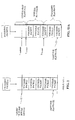
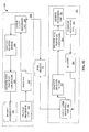
- FIG. 1 is a block diagram of a prior art communication system, wherein an Access Terminal includes a de-jitter buffer.
- FIG. 2 illustrates a prior art de-jitter buffer.
- FIG. 3 is a timing diagram illustrating transmission, receipt, and playback for packets resulting in an "underflow.”
- FIGs. 4A and 4B are timing diagrams illustrating calculation of optimal de-jitter buffer lengths in two scenarios.
- FIG. 5 is a timing diagram illustrating a run of "underflows" resulting from delayed packets.
- FIG. 6 is a flowchart illustrating the calculation of the target de-jitter buffer length.
- FIG. 7A is a timing diagram illustrating transmission of packets in a first scenario.
- FIG. 7B is a timing diagram illustrating receipt of packets without de-jitter buffer adaptation.
- FIG. 7C is a timing diagram illustrating receipt of packets with de-jitter buffer adaptation, wherein the receiver may receive a packet subsequent to an expected time for the packet.
- FIG. 8A is a flowchart illustrating one example of implicit buffer adaptation, which allows the receiver to receive a packet subsequent to an expected time for the packet.
- FIG. 8B is a state diagram of modes of operation for an adaptive de-jitter buffer.
- FIG. 9 is a timing diagram illustrating application of de-jitter buffer adaptation according to another example.
- FIG. 10 is a diagram illustrating transmission of voice information in talkspurts according to one example, wherein the de-jitter buffer delay is not sufficient to avoid collision of data.
- FIG. 11 is a block diagram of a communication system incorporating an adaptive de-jitter buffer.
- FIG. 12 is a block diagram of a portion of a receiver including an adaptive de-jitter buffer and a time warping unit.
- FIG. 13A illustrates one example of an adaptive de-jitter buffer, including compression and expansion thresholds.
- FIG. 13B illustrates one example of an adaptive de-jitter buffer, including multiple compression and expansion thresholds.
- FIG. 14 is a timing diagram illustrating time warping on receipt of packets having various delays.
- FIG. 15 is a timing diagram illustrating examples: i) compression of a silence portion of a speech segment; and ii) expansion of a silence portion of a speech segment.
- FIG. 16 is a timing diagram illustrating a speech signal, wherein portions of the speech signal may repeat.
- FIG. 17A is a diagram illustrating a speech segment, wherein the number of PCM samples in a reference window for an add-overlap operation, referred to as RWindowSize , is identified, and wherein a target or desired segment size, referred to as Segment , is identified.
- FIG. 17B is a diagram illustrating application of an add-overlap operation to compress the speech segment according to one example.
- FIG. 18A is a diagram illustrating a multiple speech segments, wherein the number of PCM samples in a reference window for an add-overlap operation, referred to as RWindowSize , is identified, and wherein a target or desired segment size, referred to as Segment , is identified in preparation for expansion of a current speech segment.
- RWindowSize the number of PCM samples in a reference window for an add-overlap operation
- FIG. 18B is a diagram illustrating application of an add-overlap operation to expand a speech sample according to one example.
- FIG. 18C is a diagram illustrating application of an operation to expand a speech sample according to an alternate example.
- FIG. 19 is a diagram illustrating expansion of packets to allow for the arrival of delayed packets and packets that arrive out of order as is the case in a Hybrid ARQ retransmission.
- FIG. 20 is a diagram illustrating a timeline of a conversation between two users.
- FIG. 21 is a flowchart illustrating enhancement at the beginning of a talkspurt according to one example.
- FIG. 22 is a diagram illustrating enhancement at the beginning of a talkspurt according to an alternate example.
- FIG. 23 is a diagram illustrating the enhancement of the end of talkspurts.
- FIG. 24 is a flowchart illustrating enhancement at the end of a talkspurt according to one example.
- FIG. 25 is a diagram illustrating operation of a prior art de-jitter buffer and decoder system, wherein the de-jitter buffer delivers packets to the decoder at regular time intervals.
- FIG. 26 is a diagram illustrating operation of an adaptive de-jitter buffer and decoder according to one example, wherein the adaptive de-jitter buffer delivers packets to the decoder at uneven time intervals.
- FIG. 27 is a block diagram illustrating an Access Terminal (AT) according to one example, including an adaptive de-jitter buffer and a time warping control unit.
- AT Access Terminal
- FIG. 28 illustrates a portion of a receiver, including an adaptive de-jitter buffer, and adapted to time warp packets according to one example.
- FIG. 29 illustrates an alternate example of a receiver, including an adaptive de-jitter buffer, and adapted to time warp packets according to another example.
- FIG. 30 is a flowchart illustrating one example of a scheduler in a decoder in one example of a receiver, including an adaptive de-jitter buffer, and adapted to time warp packets according to one example.
- FIG. 31 is a flowchart illustrating a scheduler in an audio interface unit in one example of a receiver.
- FIG. 32 illustrates the time warp unit where the scheduling is calculated outside the decoder.
- FIG. 33 illustrates the time warp unit where the scheduling is calculated in the time warp unit in decoder.
- data is formed into packets and routed through a network.
- Each packet is sent to a destination in the network, based on an assigned address contained within the packet, typically in a header.
- the end-to-end delay of packets, or the time it takes a packet to travel within the network from a first user or "sender” to a second user or “receiver” varies, depending upon channel conditions, network load, Quality of Service (QoS) capabilities of the system, and other flows competing for resources among other things.
- QoS Quality of Service
- CDMA Code Division-Multiple Access
- OFDMA Orthogonal Frequency Division Multiple Access
- W-CDMA Wideband Code Division Multiple Access
- GSM Global Systems for Mobile Communications
- IEEE standards such as 802.11 (A,B,G), 802.16, etc.
- each packet may incur a source to destination delay different from that experienced by other packets belonging to the same flow. This variation in delay is known as "jitter.” Jitter creates additional complications for receiver-side applications. If the receiver does not correct for jitter, the received message will suffer distortion when the packets are re-assembled. Some systems correct for jitter when reconstructing messages from the received packets. Such systems incorporate a de-jitter buffer, which adds a wait time, referred to as a de-jitter buffer delay.
- the de-jitter buffer When the de-jitter buffer applies a fixed, large de-jitter buffer delay, it may accommodate a high amount of jitter in arrival of packets; however; this use is not efficient since packets having a smaller delay are also processed using the large de-jitter buffer delay even though these packets could have been processed earlier. This leads to larger end-to-end delays for these packets than what may have been achieved using a smaller de-jitter buffer delay.
- VoIP systems incorporating de-jitter buffers may try to adapt to changes in packet delay.
- a de-jitter buffer may detect changes in packet delay by analyzing packet arrival statistics.
- Many de-jitter buffer implementations do not adapt their delay at all and are configured to have a conservatively large delay. In this case, the de-jitter buffer may add excessive delay to packets causing a user's experience to be sub-optimal.
- the following discussion describes an adaptive de-jitter buffer that adapts to changes in the packet delay behavior by changing its de-jitter buffer delay.
- This de-jitter buffer makes use of speech time warping to enhance its ability to track variable delay of packets.
- the following discussion is applicable to packetized communications, such as communications having periodic data transmission, low latency requirements, sequential processing of data, or a designate playback rate.
- the following discussion details a voice communication, wherein the data, or speech and silence, originate at a source and are transmitted to a destination for playback.
- the original data is packetized and encoded using a known encoding scheme.
- the encoding scheme is determined for each packet of data.
- the type of encoding of speech is different from the type of encoding of silence.
- the data appears bursty, and the speech content may appear repetitive.
- the packetized speech transmission has low latency requirements, as participants to a voice communication do not want to hear delays, but the quality of the communication allows for only limited delays.
- the packetized speech may take different paths to arrive at the receiver, however, on receipt the packets are recompiled in their original sequence. Therefore, the received packetized speech is played back sequentially. If a packet is lost in over the air transmission or in physical layer processing, the packet is not recovered, but the receiver may estimate or guess what the content of the packet was.
- the playback rate of speech communications has a predetermined playback rate or range. If the playback is outside of the range, the quality at the receiver is degraded.
- the application to speech communications is an example of application of the present discussion. Other applications may include video communications, gaming communications, or other communications having characteristics, specifications and/or requirements similar to those of speech communications. For example, video communications may desire to speed up or slow down playback. The present discussion may be desirable for such use.
- an adaptive de-jitter buffer may allow a receiver to achieve a quality of service specified by the jitter requirements of the system.
- the adaptive de-jitter buffer adapts a target de-jitter buffer length, e.g., the amount of data stored in the de-jitter buffer, to the timing and amount of data received at the adaptive de-jitter buffer. Further, an adaptive de-jitter buffer uses the status or size of the de-jitter buffer, e.g., measure of data stored in the adaptive de-jitter buffer, to determine when time warping is beneficial for processing and playback of the received data. For example, if data is arriving at the adaptive de-jitter buffer at a slow rate, the adaptive de-jitter buffer provides this information to a time warping unit, allowing the time warping unit to expand the received packets.
- a target de-jitter buffer length e.g., the amount of data stored in the de-jitter buffer
- an adaptive de-jitter buffer uses the status or size of the de-jitter buffer, e.g., measure of data stored in the adaptive de-jitter buffer, to determine when time warping is beneficial for processing and playback of the received
- time warping is within limits, which may be defined by the application and type of communication. For example, in speech communications, the time warping should not compress speech, i.e., increase the pitch, so that the listener is not able to understand the communication. Similarly, the time warping should not expand speech beyond the range. Ideally, the time warping range is defined to allow the listener little to no discomfort.
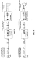
- FIG. 1 is a block diagram illustrating a digital communication system 50.
- Two Access Terminals (ATs) 52 and 82 communicate via Base Station (BS) 70.
- transmit processing unit 64 transmits voice data to an encoder 60, which encodes and packetizes the voice data and sends the packetized data to lower layer processing unit 58.
- data is then sent to BS 70.
- BS 70 processes the received data and transmits the data to AT 82, wherein the data is received at lower layer processing unit 88.
- the data is then provided to de-jitter buffer 86, which stores the data so as to conceal or reduce the impact of jitter.
- the data is sent from the de-jitter buffer 86 to decoder 84, and on to receive processing unit 92.
- data/voice is provided from transmit processing unit 94 to encoder 90.
- Lower layer processing unit 88 processes the data for transmission to BS 70.
- data is received at lower layer processing unit 58.
- Packets of data are then sent to a de-jitter buffer 56, where they are stored until a required buffer length or delay is reached. Once this length or delay is attained, the de-jitter buffer 56 begins to send data to a decoder 54.
- the decoder 54 converts the packetized data to voice data packets and sends the packets to receive processing unit 62.
- the behavior of AT 52 is analogous to AT 82.
- a storage or de-jitter buffer is used in ATs, such as the ones described above, to conceal the effects of jitter.
- an adaptive de-jitter buffer is used for packet switched communications, such as VoIP communication.
- the de-jitter buffer has an adaptive buffer memory and uses speech time warping to enhance its ability to track variable delay and jitter.
- the processing of the de-jitter buffer is coordinated with that of the decoder, wherein the de-jitter buffer identifies an opportunity or need to time warp the packets and instructs the decoder to time warp the packets.
- the decoder time warps the packets by compressing or expanding the packets, as instructed by the de-jitter buffer.
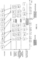
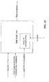
- FIG. 2 illustrates one example of a de-jitter buffer.
- the buffer is a First In, First Out (FIFO) buffer, wherein data is received in a particular order and processed in that same order; the first data processed is the first data received.
- the de-jitter buffer is an ordered list that keeps track of which packet is the next to process.
- the adaptive de-jitter buffer may be a memory storage unit, wherein the status of the de-jitter buffer is a measure of the data (or the number of packets) stored in the adaptive de-jitter buffer.
- the data processed by the de-jitter buffer may be sent to a decoder or other utility from the de-jitter buffer.
- the encoded packets may correspond to a fixed amount of speech data, e.g., 20 msec corresponding to 160 samples of speech data, at 8Khz sampling rate.
- the number of samples produced by the decoder, with time warping capabilities may vary based on whether the packet is time warped or not.
- the decoder/time warper may produce more than 160 samples.
- the decoder/time warping may produce less than 160 samples.
- alternate systems may have different playback schemes, such as other than 20 ms vocoding.
- a de-jitter buffer has a target de-jitter buffer length.
- the target de-jitter buffer length refers to the required amount of data to be accumulated in the de-jitter buffer before starting to playback the first packet.
- the target de-jitter buffer length may refer to the amount of time the first packet in the de-jitter buffer needs to be delayed before being played back.
- the target de-jitter buffer length is illustrated in FIG. 2 .
- FIG. 2 illustrates a de-jitter buffer, wherein the vocoder packet first received into the de-jitter buffer is the next packet scheduled for output from the de-jitter buffer.
- the de-jitter buffer includes sufficient packets to achieve the required de-jitter buffer delay. This way, the de-jitter buffer smooths the jitter experienced by packets and conceals the variation in packet arrival time at the receiver.
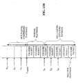
- FIG. 3 illustrates transmission, receipt, and playback timelines for packets in various scenarios.
- the first packet, PKT 1 is transmitted at time to and is played back upon receipt at time t 1 .
- Subsequent packets, PKT 2, PKT 3, and PKT 4 are transmitted at 20 ms intervals after PKT 1.
- decoders playback packets at regular time intervals (e.g. 20 ms), from the first packet's playback time.
- a decoder plays back packets at regular 20 ms intervals
- a first received packet is played back at time t 1
- subsequent packets will be played back 20 ms after time t 1 , 40 ms after time t 1 , 60 ms after time t 1 , etc.
- PKT 2 is received before its anticipated playback time, t 2 .
- This condition is referred to as an underflow.
- An underflow occurs when the playback utility is ready to play a packet, but the packet is not present in the de-jitter buffer. Underflows typically cause the decoder to produce erasures and degrade playback quality.
- FIG. 3 further illustrates a second scenario, in which the de-jitter buffer introduces a delay, t djb before the playback of the first packet.
- the de-jitter buffer delay is added to enable the playback utility to receive packets (or samples) every 20 ms.
- the addition of the de-jitter buffer delay allows PKT 3 to be played 20 ms after playback of PKT 2.
- the delaying of the playback by t djb allows the third packet to be played out without an underflow being caused.
- introduction of the de-jitter buffer delay may reduce underflows and prevent speech quality from being degraded.
- Speech consists of periods of talkspurts and silence periods.
- the expansion/compression of silence periods has minimal or no impact on speech quality. This allows the de-jitter buffer to delay the playback of the first packet differently for each talkspurt.
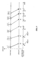
- FIGs. 4A and 4B illustrate transmission and receipt timelines for different talkspurts.
- the amount of de-jitter buffer delay is determined to prevent underflows. This is referred to as "optimal de-jitter buffer delay.”
- the optimal de-jitter buffer delay is related to the target de-jitter buffer length. In other words, the target de-jitter buffer length is determined to allow enough data to be stored in the buffer so packets are played back consistent with playback utility specifics.
- the optimal de-jitter buffer delay may be determined by the greatest end-to-end delay experienced by the system. Alternately, the optimal de-jitter buffer delay may be based on an average delay experienced by the system. Other methods for determining the optimal de-jitter buffer delay may also be implemented specific to a given criteria or system design. Further, the target de-jitter buffer length is determined so as to effect the optimal de-jitter buffer delay, and therefore, the target de-jitter buffer length may be calculated based on received packet rates, Packet Error Rate (PER) or other
- FIGs. 4A and 4B illustrate optimal de-jitter buffer delays for two examples. As illustrated, the time between transmission and receipt of sequential packets varies over time. As PKT 3 has the longest delay from transmission to receipt, this difference is used to determine an optimal delay for de-jitter processing.
- the second scenario obviated an underflow (occurring when the decoder expected a packet and the playback utility was ready to play a packet, but no packets were present in the packet storage buffer).
- PKT 2 is played back after a predetermined interval, 20 ms, subsequent to t 1 , wherein t 1 is the playback time of PKT 1.
- t 1 is the playback time of PKT 1.
- PKT 3 is scheduled or anticipated for playback at time t 3
- PKT 3 is not received until after time t 3 .
- the playback utility is ready to playback PKT 3 but this packet is not present in the storage buffer.
- PKT 3 Since PKT 3 is not available for playback at the anticipated time, and is not played back, there results a large amount of jitter and an underflow with respect to PKT 3.
- PKT 4 is played back at t 4 , the anticipated playback time for PKT 4. Note the anticipated time t 4 is calculated from the time t 3 . Since each packet may contain more than one voice packet, the loss of packets due to underflows degrades voice quality.
- Another scenario for consideration involves a run of "underflows due to delayed packets" as illustrated in FIG. 5 , wherein transmission, receipt and anticipated playback time of packets are illustrated in time.
- each packet is received a short time after its anticipated playback time.
- anticipated playback time for PKT 50 is to but PKT 50 is not received until time t 0 ' after t 0 .
- the next packet, 51 is anticipated at time t 1 but is not received until time t 1 ', after t 1 .
- This causes a run of underflows leading to a high percentage of "delayed underflows," underflows due to a delayed packet, and thus, higher end-to-end delays.
- a de-jitter buffer which delays playback by a large amount will be successful in keeping underflows to a minimum.
- Such a do-jitter buffer introduces a large de-jitter buffer delay into the end-to-end delay of packets.
- a large end-to-end delay may lead to difficulty in maintaining the flow of a conversation. Delays greater than 100 ms may cause the listening party to think that the speaking party has not finished talking. Good quality, therefore, ideally considers both avoidance of underflows and reduction of end-to-end delay.
- a problem exists as resolution of one problem may worsen the other. In other words, smaller end-to-end delays generally result in more underflows, and vice versa. There is therefore, a need to balance these competing goals. Specifically, there is a need for the de-jitter buffer to track and avoid underflows while reducing end-to-end delay.
- a design goal of an adaptive de-jitter buffer is to allow the system to target a particular "underflow rate" of voice packets, while at the same time achieving low end-to-end delays.
- Packet underflows at the de-jitter buffer may occur when there are missing packets.
- a packet may be missing when it is lost or delayed.
- a lost packet causes an underflow when dropped before it reaches the receiver, such as when it is dropped somewhere in the access network, for example on the physical layer or the forward link scheduler.
- the underflow cannot be corrected by using a de-jitter buffer delay because the packet never arrives at the de-jitter buffer.
- an underflow may occur as a result of a packet that is delayed, and arrives after its playback time.
- the adaptive de-jitter buffer may also track underflows due to lost packets.
- the number of underflows due to a delayed packet may be controlled by trading off underflows for de-jitter buffer delay.
- a value representing the target percentage of underflows due to delayed packets is referred to as "underflow target.” This value is the target value for operation of the de-jitter buffer and is selected so as to keep end-to-end delay within reasonable limits. In one instance, a value of 1% (0.01) may be used as the "underflow target.” Another example uses a value of 0.5% (0.005). In order to achieve an "underflow target,” the de-jitter buffer delay may be adapted.
- the filtered value of percentage of underflows due to delayed packets may be used to adapt the de-jitter buffer delay.
- the de-jitter buffer delay is updated as illustrated in FIG. 6 . As illustrated in FIG.
- the initial de-jitter buffer delay may be set to a constant value such as 40 ms.
- the TARGET_VALUE is a targeted value of "delayed underflows" (e.g., 1%).
- PER delay is a filtered value of the "delayed underflow" rate of packets where the parameters of the filter allow the TARGET_VALUE to be achieved.
- the last_PER delay is the value of PER delay at the previous updating of the de-jitter buffer delay.
- DEJITTER_DELAY is the target de-jitter buffer length as defined hereinabove. In the present example, CONSTANT is equal to 20 ms.
- MIN_JITTER and MAX_JITTER are the minimum and maximum values of the de-jitter buffer delay; according to one example these are set at 20 ms and 80 ms, respectively.
- MIN_JITTER and MAX_JITTER may be estimated based on system simulation.
- the values (MIN_JITTER, MAX_JITTER, CONSTANT) may be optimized depending on the communications system in which the de-jitter buffer is deployed.
- PER_CONSTANT is the time constant for the filter used to estimate PER delay .
- the value for this constant determines the memory of the filter and allows the TARGET_VALUE to be achieved.
- Current_PER delay is the rate of "delayed underflows" observed between the last update of PER delay and the current update.
- Current_PER delay is defined as the ratio of the number of delayed underflow packets to the total number of packets received between the last update of PER delay and the current update.
- Current_PER delay Number of Delayed Underflows Since Last Update Number of Packtes Re ⁇ ceived Since Last Update
- the process 100 for calculating and updating the de-jitter buffer delay begins at step 101 by initializing the DEJITTER_DELAY. By comparing the PERdelay is compared to the TARGET_VALUE at step 102. If the PERdelay is less than the TARGET_VALUE, the CONSTANT value is subtracted from the DEJITTER_DELAY at step 104. If the PERdelay is larger than the TARGET_VALUE at step 102, and PERdelay is greater than TARGET_VALUE and greater than or equal to LAST_PERDELAY at step 103, is not less than last PERdelay at step 102, then processing continues to decision 108.
- the DEJITTER_DELAY is set to the DEJITTER_DELAY plus the CONSTANT value at step 108.
- step 103 if PERdelay is not greater than TARGET_VALUE and not greater than or equal to LAST_PERDELAY, processing continues to step 110.
- step 104 the DEJITTER_DELAY is set equal to the maximum of MIN_JITTER and DEJITTER_DELAY at step 110.
- step 112 processing continues to step 112 to set the DEJITTER_DELAY equal to the minimum of MAX_JITTER and DEJITTER_DELAY at step 112.
- the de-jitter buffer may enter a mode where it tracks delay (instead of tracking the underflow rate.)
- the tracked delay may be the end-to-end delay or the de-jitter buffer delay.
- the de-jitter buffer enters a "track delay" mode when the target underflow rate may be easily met. This means the de-jitter buffer is able to achieve a lower underflow rate than the target underflow rate for some period of time. This period of time may be anywhere from a few hundred ms to a few sec.
- the de-jitter buffer has a target delay value. This is similar to the underflow target value described above. Equation (1) above may be used for targeting an underflow rate may be used in an analogous manner to calculate a Target Delay value. When the de-jitter buffer enters this mode where it targets a Target Delay value, this may allow it to reduce its Target underflow rate as long as the Target Delay is being maintained.
- the decoder may expect to play a packet, which has not yet been received. This situation is shown in FIG. 5 , where the anticipated playback time of PKT 50 is t 0 , but PKT 50 is received after this time. Similarly, PKT 51 is received after its anticipated playback time t 1 , PKT 52 is received after its anticipated playback time t 2 and so on. It should be noted here that packets arrive fairly regularly, but because PKT 50 was received slightly after its anticipated playback time, it caused all subsequent packets also to miss their playback times. If, on the other hand, the decoder could insert an erasure at t 0 and still playback PKT 50 at t 1 , it would allow all packets to meet their playback times. By playing PKT 50 after an erasure in lieu of PKT 50 has been played, the de-jitter buffer length is effectively adapted.
- PKT 1, PKT 2 and PKT 3 are received at times t 1 , t 2 , and t 3 , respectively.
- time t 4 it is anticipated that PKT 4 will be received, but PKT 4 has not yet arrived.
- packets are expected to be received every 20 ms. In the present illustration, PKT 2 is received 20 ms after PKT 1 and PKT 3 is received 40 ms after PKT 1.
- PKT 4 is expected to be received 60 ms after PKT 1 but does not arrive until 80 ms after PKT 1.
- an initial delay is introduced at the de-jitter buffer prior to playback of the first packet received, PKT 1.
- the initial delay is D init .
- PKT 1 will be played back by the buffer at time D init , PKT 2 at time D init + 20 ms, PKT 3 at D init + 40 ms, etc.
- PKT 4 fails to arrive at the expected time, D init + 60 ms, an erasure may be played back by the de-jitter buffer.
- the de-jitter buffer will seek to play PKT 4. If PKT 4 still has not arrived, another erasure may be sent at time D init + 80 ms.
- Erasures will continue to be played back until PKT 4 arrives at the de-jitter buffer. Once PKT 4 arrives at the de-jitter buffer, PKT 4 is then played back. Such processing results in delay, as no other packets are played back until PKT 4 is received.
- the system may apply a reset of the process, allowing playback of packets subsequent to PKT 4 without playback of PKT 4.
- end-to-end delay of the de-jitter buffer has the potential of increasing as erasures may continue to be sent for a long period of time before PKT 4 arrives.
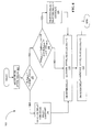
- Implicit buffer adaptation (IBA) process 200 is illustrated by a flowchart in FIG. 8A .
- the process 200 may be implemented in a controller within an adaptive de-jitter buffer, such as in output controller 760 or in de-jitter buffer controller 756.
- the process 200 may reside in other portions within a system supporting an adaptive de-jitter buffer.
- a request is received at the adaptive de-jitter buffer to provide a next packet for playback.
- the next packet is identified as a packet having an index i in a sequence, specifically, PKT[ i ].
- IBA Implicit Buffer Adaption
- processing continues to 206 to process according to IBA mode; and if IBA mode is disabled, processing continues to 226 to process without IBA mode.
- the adaptive de-jitter buffer provides PKT [ i ] for playback at step 208.
- the controller initiates playback of an erasure at step 222; and index i is incremented at step 224.
- the controller checks for up to two (2) packets in response to a request for a next packet, such as received at step 202. This effectively implements a packet window over which the controller searches for received packets. Alternate examples may implement a different window size, e.g., search for three (3) packets, which in this example would be packet sequence numbers i , i +1, and i +2.
- IBA mode if IBA mode is not enabled, processing continues to 226 to determine if PKT [ i ] is received. If received, PKT [ i ] is provided for playback at step 228, and index, i, is incremented at step 230. If PKT [ i ] is not received at 226, the adaptive de-jitter buffer provides an erasure for playback at step 232. IBA mode is enabled, as PKT [ i ] was not received and an erasure was played back instead.
- FIG. 8B is a state diagram related to IBA mode.
- the controller When in normal mode 242, if the adaptive de-jitter buffer provides PKT [ i ] for playback, the controller stays in normal mode. The controller transitions from normal mode 242 to IBA mode 240 when an erasure is played back. Once in IBA mode 240, the controller remains there on playback of an erasure. The controller transitions from IBA mode 240 to normal mode 242 on playback of PKT [ i ] or PKT [ i +1].
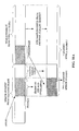
- FIG. 9 is one example of a de-jitter buffer implementing IBA such as illustrated in FIGs. 8A and 8B .
- the playback utility requests samples for playback from a decoder.
- the decoder then requests packets from the de-jitter buffer sufficient to allow uninterrupted playback by the playback utility.
- the packets carry voice communications, and the playback utility plays back a sample every 20 ms.
- Alternate systems may provide the packetized data from the de-jitter buffer to the playback utility through other configurations, and the packetized data may be other than voice communications.
- the de-jitter buffer is illustrated in FIG. 9 as a stack of packets.
- the buffer receives PKT 49 first, and then subsequently receives PKT 50, 51, PKT 52, PKT 53, etc.
- the packet number in this illustration refers to a sequence of packets. In a packetized system, however, there is no guarantee the packets will be received in this order.
- packets are received in the same numerical sequence as transmitted, which is also the order of playback.
- subsequently received packets are stacked on top of previously received packets in the de-jitter buffer; for instance, PKT 49 is stacked on top of PKT 50, PKT 51 is stacked on top of PKT 50, etc.
- the packet at the bottom of the stack in the de-jitter buffer is the first to be sent to the play back utility. Note also, in the present illustration, the target de-jitter buffer length is not shown.
- the receipt of packets, anticipated receipt time of packets and playback time of packets is graphed versus time.
- the updated buffer status is illustrated each time a packet is received. For example, PKT 49 is received at time t 0 , wherein PKT 49 is anticipated for playback at time t 1 .
- the buffer status on receipt of PKT 49 is illustrated at the top of the graph above time t 0 , the receipt time of PKT 49.
- the time receipt for each packet received at the de-jitter buffer is graphed as RECEIVED.
- the ANTICIPATED PLAYBACK time is graphed just below the RECEIVED time. Playback times are identified as PLAYBACK.
- the next packet for playback is PKT 49, which is anticipated to be played back at time to.
- the next sequential packet is expected at time t 1 , etc.
- the first packet, PKT 49 is received before the anticipated playback time of to. Therefore, PKT 49 is played back at time t 0 as anticipated.
- the next packet, PKT 50 is anticipated at time t 1 . Receipt of PKT 50, however, is delayed, and an erasure is sent to the playback utility, in lieu of PKT 50.
- the delay of PKT 50 causes an underflow as previously described.
- PKT 50 is received after the anticipated playback time, t 1 , and before the next anticipated playback time, t 2 . Once received, PKT 50 is stored in the de-jitter buffer.
- the system looks for the lowest sequential packet in the de-jitter buffer; and PKT 50 is provided to the playback utility for playback at time t 2 .
- PKT 50 is played back later and the rest of the sequence resumed from that point.
- subsequent packets, PKT 51, PKT 52, etc. are received and played back in time to avoid further erasures.
- IBA increases the end-to-end delay of packets, this is actually not the case. Since IBA leads to a smaller number of underflows, the de-jitter buffer value as estimated from Equation 1 above, is maintained at a smaller value. Therefore, the overall effect of IBA may be a decrease in the average end-to-end delay of packets overall.
- a talkspurt refers to the speech portion of a voice communication, wherein a voice communication includes speech and silence portions, consistent with normal speech patterns.
- a vocoder produces one type of packet for speech and another type for silence.
- the speech packets are encoded at one encoding rate, and silence is encoded at a different encoding rate.
- the de-jitter buffer identifies the type packet from the encoding rate.
- the de-jitter buffer assumes a speech frame is part of a talkspurt.
- the first non-silence frame is the beginning of a talkspurt.
- the talkspurt ends when a silence packet is received.
- the de-jitter buffer adjusts the de-jitter buffer length according to the type of packets received. In other words, the system may decide to reduce the length of the de-jitter buffer required for silence portions of the communication.
- the IBA methods may be applicable to any communications where the playback is according to a predetermined timing scheme, such as a fixed rate, etc.
- a talkspurt is generally made up of multiple packets of data.
- playback of a first packet of a talkspurt may be delayed by a length equal to the de-jitter buffer delay.
- the de-jitter buffer delay may be determined in various ways.
- the de-jitter buffer delay may be a calculated de-jitter buffer delay, based on an algorithm such as Equation 1 above.
- the de-jitter buffer delay may be the time it takes to receive voice data equal to the length of the de-jitter buffer delay.
- the de-jitter buffer delay may be selected as the smaller of the aforementioned values.
- the de-jitter buffer delay is calculated as 60 ms using Equation 1 and the first packet of a talkspurt is received at a first time t 1 .
- the adaptive de-jitter buffer data is equal to the de-jitter delay, 60 ms.
- the time from receipt of a packet at the adaptive de-jitter buffer to playback is 60 ms.
- the target length of the adaptive de-jitter buffer may be set to achieve a 60ms delay. Such calculation determines how many packets are to be stored in order to meet the delay time.
- the adaptive de-jitter buffer monitors the filling and emptying of data from the buffer and adjusts the output of the buffer to maintain the buffer at the target delay length, i.e., the amount of data to achieve the target delay time.
- ⁇ MIN (de-jitter buffer delay, time taken to receive voice data equal to de-jitter delay).
- Subsequent packets of the talkpsurt are delayed by ⁇ plus the time it takes to playback the previous packets.
- the de-jitter buffer delay of subsequent packets of the same talkspurt is implicitly defined once the de-jitter buffer delay for the first packet has been defined. In practice, this definition of de-jitter buffer delay may require additional considerations to accommodate for situations such as those illustrated in FIG. 10 .
- FIG. 10 illustrates the transmission of voice information in talkspurts.
- Talkspurt 150 is received at time to and talkspurt 154 is received at time t 2 .
- the adaptive de-jitter buffer may store the received data and determine the delays for playback of each talkspurt.
- talkspurt 150 is received at the adaptive de-jitter buffer at time t 0 , wherein the adaptive de-jitter buffer delay time is calculated as 80ms.
- the de-jitter buffer delay is added to the receipt time to result in a playback time. In this way, talkspurt 150 is delayed by the adaptive de-jitter buffer by 80ms before playback.
- the calculated de-jitter buffer delay of 40 ms (for packet 154) does not allow sufficient time for talkspurt 150 to finish playing.
- the first packet of talkspurt 154 should be played after the last packet of talkspurt 150 has been played with a silence period in between.
- talkspurt 150 and talkspurt 154 overlap from time t 3 to t 4 . Therefore, the playback method in this scenario is not desirable.
- calculation of the de-jitter buffer delay for a packet may consider the playback timing of previously played back packets, so as to avoid overlap or conflict.
- the de-jitter buffer delay is calculated or updated at the beginning of a talkspurt. Restricting the update of the de-jitter buffer delay to the beginning of a talkspurt, however, may be limiting, as talkspurts often vary in length and operating conditions may change during a talkspurt. Consider the example of FIG. 10 . Thus, there may be a need to update the de-jitter buffer delay during a talkspurt.
- the adaptive de-jitter buffer may work in coordination with a decoder to time warp packets as described herein.
- FIG. 11 is a block diagram of a system including two receivers communicating through a network element.
- the receivers are AT 252 and AT 282; as illustrated ATs 252 and 282 are adapted for communication through a BS 270.
- transmit processing unit 264 transmits voice data to an encoder 260 which digitizes the voice data and sends the packetized data to lower layer processing unit 258. Packets are then sent to BS 270.
- the data is first processed in the lower layer processing unit 258, from which packets of data are provided to an adaptive de-jitter buffer 256. Received packets are stored in adaptive de-jitter buffer 256 until the target de-jitter buffer length is reached.
- the adaptive de-jitter buffer 256 sends data to a decoder 254.
- compression and expansion to implement time warping may be performed in the decoder 254 which converts the packetized data to voice data and sends the voice data to a receive processing unit 262.
- time compression and expansion may be performed within the adaptive de-jitter buffer by a controller (not shown).
- the behavior of AT 282 is similar to that of AT 252.
- AT 282 transmits data on a path from transmit processing unit 294 to encoder 290 to lower layer processing unit 288 and finally to BS 270.
- AT 282 receives data on a path from lower layer processing unit 288 to adaptive de-jitter buffer 286 to decoder 284 to receive processing unit 292. Further processing is not illustrated but may affect the playback of data, such as voice, and may involve audio processing, screen displays, etc.
- the de-jitter buffer equations given in Equation 1 calculate the de-jitter buffer delay at the beginning of a talkspurts.
- the de-jitter buffer delay may represent a specific number of packets, such as determined by talkspurts, or may represent an expected time equivalent for playback of data, such as voice data. Note here that the de-jitter buffer has a target size, and this determines the amount of data the de-jitter buffer expects to see stored at all points of time.
- Variation in packet delay due to channel conditions, and other operating conditions, may lead to differences in packet arrival time at the adaptive de-jitter buffer. Consequently, the amount of data (number of packets) in the adaptive de-jitter buffer may be less or greater than the calculated de-jitter buffer delay value, DEJITTER_DELAY. For instance, packets may arrive at the de-jitter buffer at a slower or faster rate than the packets were generated originally at the encoder. When packets arrive at the de-jitter buffer at a slower rate than expected, the de-jitter buffer may begin to deplete because incoming packets will not replenish outgoing packets at the same rate.
- the de-jitter buffer may start increasing in size because packets are not leaving the de-jitter buffer as fast as they are entering.
- the former condition may lead to underflows, whereas the latter condition may cause high end-to-end delays due to larger buffering times in the de-jitter buffer.
- the latter is important because if the end-to-end delay of the packet data system decreases (AT moves to a less loaded area or user moved to an area with better channel quality) it is desirable to incorporate this delay reduction into the playback of the speech.
- the end-to-end delay is an important speech quality factor and any reduction on playback delay is perceived as an increase of conversational or speech quality.
- a do-jitter buffer employs time warping.
- Time warping involves expanding or compressing the duration of a speech packet.
- the de-jitter buffer implements time warping by expanding speech packets when the adaptive de-jitter buffer starts to deplete, and compressing speech packets when the adaptive de-jitter buffer becomes larger than DEJITTER_DELAY.
- the adaptive de-jitter buffer may work in coordination with a decoder to time warp packets. Time warping provides substantial improvement in speech quality without increasing the end-to-end delay.
- FIG. 12 is a block diagram of an example of an adaptive de-jitter buffer implementing time warping.
- the physical layer processing unit 302 provides data to the data stack 304.
- the data stack 304 outputs packets to the adaptive de-jitter buffer and control unit 306.
- the Forward Link (FL) Medium Access Control (MAC) processing unit 300 provides a handoff indication to de-jitter processing unit 306.
- the MAC layer implements protocols for receiving and sending data on the physical layer, i.e. over the air.
- the MAC layer may include security, encryption, authentication, and connection information.
- the MAC layer contains rules governing the Control Channel, the Access Channel, as well as the Forward and Reverse Traffic Channels.
- the target length estimator 314 provides the target de-jitter buffer length to the de-jitter buffer using the calculations given in Equation 1.
- Input to the target length estimator 314 includes packet arrival information and current packet error rate (PER). Note, alternate configurations may include the target length estimator 314 within the adaptive de-jitter buffer and control unit 306.
- adaptive de-jitter buffer and control unit 306 further includes playback control which controls the rate of data provided for playback.
- packets are sent to a Discontinuous Transmission (DTX) unit 308, wherein DTX unit 308 provides background noise information to decoder 310 when speech data is not being received.
- DTX Discontinuous Transmission
- the packets provided by the adaptive de-jitter buffer and control unit 306 are ready for decode processing and may be referred to as vocoder packets.
- the Decoder 310 decodes the packets and provides Pulse Code Modulated (PCM) speech samples to the time warping unit 312.
- PCM Pulse Code Modulated
- the time warping unit 312 may be implemented within the decoder 310.
- Time warping unit 312 receives a time warping indicator from adaptive de-jitter buffer and control unit 306.
- the time warping indicator may be a control signal, an instruction signal or a flag.
- a time warp indicator may be a multistate indicator, having for instance, a compression, expansion, and no time warping. There may be different values for different compression levels and/or different expansion levels.
- the time warping indicator instructs the time warping unit 312 to expand or compress data.
- the time warping indicator indicates expand, compress, or no warping.
- the time warping indicator may be considered a control signal initiating action at the time warping unit 312.
- the time warping indicator may be a message specifying how to expand or compress the packets.
- the time warping indicator may identify the packets to time warp as well as which action to take, expand or compress. Still further, the time warping indicator may provide a choice of options to the time warping unit 312.
- the DTX module modifies the stream of erasures provided by the de-jitter buffer into a stream of erasures and silence frames that the decoder uses to reconstruct a more precise and higher quality background noise.
- the time warp indicator turns time warping on and off.
- the indicator identifies the amount of compression and expansion used for playback.
- the time warping unit 312 may modify the samples from the decoder and provides the samples to audio processing 316, which may include an interface and conversion unit, as well as an audio driver and speaker.
- time warping indicator identifies when to compress or when to expand, there is a need to determine how much time warping to apply to a given packet.
- the amount of time warping is fixed, wherein packets are time warped according to speech cycle, or pitch.
- the time warping indicator is communicated as a percentage of a target expansion or a target compression level. In other words, the time warping indicator instructs to compress by a given percent or expand by a given percent.
- Tone based communications include, but are not limited to, TeleTYpewriter/Telecommunications Device for the Deaf (TTY/TDD) information, applications using keypad entries, or other applications using tone-based communications.
- the decoder In such communications the length of the tone carrier information, and therefore, modifying the pitch or tone length, such as compression or expansion at playback, may result in loss of that information.
- the decoder also provides the status of its inband processing of such communication. This indication is used to mask the time warping indications provided by the de-jitter buffer. If the decoder is processing packets with TTY/TDD information, time warping should be disabled. This may be done in 2 ways; providing the TTY/TDD status to the dejitter buffer controller, or providing the TTY/TDD status to the time warping unit.
- the controller should not indicate any expansion or compression indication when the vocoder indicates processing of TTY/TDD. If the decoder TTY/TDD status is provided to the time warping unit, this acts as a filter and the time-warping unit does not act upon time warping indications if the decoder is processing TTY/TDD information.
- the adaptive de-jitter buffer and control unit 306 monitors the rate of incoming data and generates a time warp indicator when too many or too few packets are available or buffered.
- the adaptive de-jitter buffer and control unit 306 determines when to time warp and which action to take.
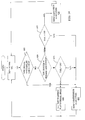
- FIG. 13A illustrates operation of one example of an adaptive de-jitter buffer making the time warp determinations using compression and expansion thresholds.
- the de-jitter buffer accumulates packets which may have arrived at irregular time intervals.
- the due-jitter target length estimator 314 generates a target de-jitter buffer length; the target de-jitter buffer length is then applied to the de-jitter buffer.
- an adaptive de-jitter buffer and control unit 306 uses the de-jitter buffer length value to make control decisions about de-jitter buffer operation and to control playback.
- the compression threshold and expansion threshold indicate when compression or expansion is triggered, respectively. These thresholds may be specified as a fraction of the de-jitter target length.
- the target de-jitter buffer length is given as L Target .
- the compression threshold is given as T Compress
- the expansion threshold is given as T Expand .
- T Compress When the de-jitter buffer length increases above the compression threshold, T Compress , the de-jitter buffer indicates to the decoder that packets should be compressed.
- the de-jitter buffer indicates to the decoder that packets should be expanded, and effectively played back at a slower rate
- target operation is between T Compress and T Expand .
- the values for expansion and compression thresholds are set to 50% and 100%, of the target value of the de-jitter buffer, respectively. While in one example, time warping may be performed inside the decoder, in alternate examples, this function may be performed outside the decoder, for instance subsequent to decoding. However, it may be simpler to time warp the signal before synthesizing the signal. If such time warping methods were to be applied after decoding the signal, the pitch period of the signal would need to be estimated.
- the de-jitter buffer length may be larger, for instance in a W-CDMA system.
- a time warp threshold generator may generate multiple compression and expansion thresholds. These thresholds may be calculated in response to operating conditions. Multi-level thresholds are illustrated in FIG. 13B . T C1 is a first compression threshold, T C2 is a second compression threshold and T C3 is a third compression threshold. Also illustrated are T E1 ; T E2 and T E3 representing three different values for expansion thresholds. The thresholds may be based on a percentage of time warping (how many packets get time warped), on compressed packets, on a percentage of expanded packets or on a ratio of these two values.
- the number of thresholds may be changed as needed, in other words, more or less thresholds may be needed.
- Each one of the thresholds relates to a different compression or expansion rate, for instance, for systems requiring finer granularity, more thresholds may be used, and for coarser granularity, less thresholds may be used.
- T E1 , T E2 and TE 3 , etc. may be a function of target delay length.
- Threshold may be changed by tracking delayed underflows and based on error statistics such as PER.
- FIG. 14 illustrates playback of packets with and without time warping.
- PKT 1 is transmitted at time t 1
- PKT 2 is sent at time t 2 , and so on.
- the packets arrive at the receiver as indicated, wherein PKT 1 arrives at t 2 ', and PKT 2 arrives at t 2 ".
- the playback time without using time warping is given as PLAYBACK WITHOUT WARPING.
- the playback time using time warping is given as PLAYBACK WITH WARPING.
- the anticipated playback time of packets is at fixed time intervals. During playback, ideally each packet arrives before the anticipated playback time. If a packet arrives too late for playback at the anticipated time, there may be an impact on playback quality.
- PKTs 1 and 2 are received on time, and they are played back, without time warping.
- PKT 3 and PKT 4 are both received at the same time, t 4 '.
- the receipt time for both packets is satisfactory, because each packet is received before the associated anticipated playback times, t 4 " for PKT 3 and t 5 ' for PKT 4.
- PKTs 3 and 4 are played back on time without warping.
- An erasure is played back in lieu of PKT 5 at the anticipated playback time.
- PKT 5 arrives later, after the erasure has begun playback.
- PKT 5 In a first scenario without warping, PKT 5 is dropped and PKT 6 is received and played back at the next anticipated playback time. Note, in this case, PKT 6 was received in time for playback.
- PKT 5 and all packets subsequent to PKT 5 are delayed, each packet may arrive too late for anticipated playback, and result in a string of erasures.
- information is lost i.e., PKT 5 is dropped in the first scenario; PKT 5 and subsequent packets are lost in the second scenario.
- IBA Intra-Fi Protected Access
- Such playback without time warping may increase the overall end-to-end delay in a communication system.
- inter-packet delays may result in lost information, or delays in playback.
- time warping By implementing time warping, when PKT 5 arrives after its anticipated playback time, packets are expanded and an erasure may be avoided. For instance, expanding PKT 4 may cause playback in 23 ms instead of 20 ms. PKT 5 is played back when it is received. This is sooner than it would have been played back had an erasure been sent instead (as illustrated in one alternative for the playback without time warping but with IBA as described in FIG. 14 .) Expanding PKT 4 instead of sending an erasure results in less degradation of playback quality. Thus, time warping provides for better overall playback quality as well as latency reduction. As illustrated in FIG. 14 , packets subsequent to PKT 5 are played back earlier using time warping than if not using a time warping technique. In this specific example, PKT 7 is played back at time t 9 , when time warping is used, which is earlier than without time warping.
- FIG. 15 illustrates examples of "silence compression” and "silence expansion” due to differences in de-jitter delay from one talkspurt to another.
- the shaded regions 120, 124 and 128 represent talkspurts, while unshaded regions 122 and 126 represent silence periods of the received information.
- talkspurt 120 begins at time t 1 and ends at time t 2 .
- de-jitter buffer delay is introduced and therefore playback of talkspurt 120 begins at time t 1 '.
- the de-jitter buffer delay is identified as the difference between time ti' and time t 1 .
- silence period 122 begins at time t 2 and ends at time t 3 .
- the silence period 122 is compressed and played back as silence period 132 from time t 2 ' to t 3 ', which is less than the original time duration of the received silence period 122.
- Talkspurt 124 begins at time t 3 and ends at time t 4 at the source.
- Talkspurt 104 is played back at the receiver from time t 3 ' to time t 4 '.
- Silence period 126 (time t 4 to t 5 ) is expanded at the receiver on playback as silence period 136, wherein (t 5 ' - t 4 ') is greater than (t 5 - t 4 .)
- a silence period may be compressed when the de-jitter buffer needs to playback packets sooner and expanded when a de-jitter buffer needs to delay the playback of packets.
- compression or expansion of silence periods causes insignificant degradation in voice quality.
- adaptive de-jitter delays may be achieved without degrading voice quality.
- the adaptive de-jitter buffer compresses and expands the silence periods as identified and controlled by the adaptive de-jitter buffer.
- time warping refers to the adaptive control of playback in response to the arrival time and length of received data.
- Time warping may be implemented using compression of data on playback, expansion of data on playback, or using both compression and expansion of data on playback.
- a threshold is used to trigger compression.
- a threshold is used to trigger expansion.
- two triggers are used: one for compression, and one for expansion.
- Still other examples may employ multiple triggers, indicating various levels of time warping, e.g. fast playback at different rates.
- Time warping may also be performed inside the decoder.
- Techniques for performing decoder time-warping are described in co-pending application number 11/123,467 , entitled “Time Warping Frames Inside the Vocoder by Modifying the Residual,” filed May 5, 2005.
- time warping incorporates a method for "merging" segments of speech.
- Merging speech segments involves comparing speech samples in at least two consecutive segments of speech and if a correlation is found between compared segments, creating a single segment of at least two consecutive segments.
- Merging of speech is done while attempting to preserve speech quality.
- Preserving speech quality and minimizing introduction of artifacts, such as sounds which degrade the quality for the user, including "clicks" and "pops,” into the output speech is accomplished by carefully selecting the segment to merge.
- the selection of speech segments is based on segment similarity or correlation. The closer the similarity of the speech segments, the better the resulting speech quality and the lower the probability of introducing a speech artifact.
- FIG. 16 illustrates a speech signal plotted over time.
- the vertical axis represents the amplitude of the signal; and horizontal axis represents time.
- the speech signal has a distinctive pattern, wherein portions of the speech signal repeat over time.
- the speech signal includes a first segment from time t 1 to t 2 , which repeats as a second segment during t 2 to t 3 . When such repetition of a segment is found, one of the segments or more, such as that from time t 2 to time t 3 , may be eliminated with little or effectively no impact on the playback quality of the sample.
- Equation 4 may be used to find a relationship between the two segments of speech. Correlation is a measure of the strength of the relationship between the two segments. Equation 4 provides an absolute and bounded correlation factor (from -1 to +1) as a measure of the strength of the relationship, wherein a low negative number reflects a weaker relation, i.e., less correlation, than a high positive number, which reflects a stronger relation, i.e., more correlation. If application of Equation 4 indicates "good similarity," time warping is performed. If application of Equation 4 shows little similarity, artifacts may be present in a merged segment of speech.
- Corr d ⁇ i x i - mx ⁇ y ⁇ i - d - my ⁇ i x i - mx ⁇ ⁇ 2 ⁇ i y ⁇ i - d - my ⁇ ⁇ 2
- Equation 4 x and y represent the two segments of speech, m represents the window over which the correlation between the two segments is being calculated, d represents the correlation portion and i is an index. If application of Equation 4 indicates segments may be merged without introducing artifacts, merging may be done using an "add-overlap" technique. The add-overlap technique combines the compared segments and produces one speech segment out of two separate speech segments.
- the resultant samples may be Pulse Code Modulation (PCM) samples.
- PCM Pulse Code Modulation
- Each PCM sample has a predetermined format defining the bit length and format of the PCM sample. For example, a 16 bits signed number may be the format to represent a PCM sample.
- the add-overlap technique produced by application of Equation 5 includes weighting to provide a smooth transition between the first PCM sample of Segment1 and the last PCM sample of Segment2.
- RWindowSize is the number of PCM samples in a reference window
- OutSegment is the size of the resulting add-overlapped segment.
- WindowSize is equal to the reference window size and " Segment " is the target segment size.
- FIG. 17A a speech segment made up of 160 PCM samples is shown.
- RWindowSize is represented by PCM samples 0 - 47.
- PCM samples 0-47 correspond to the number of samples in the reference window of size WindowSize.
- Segment refers to the size of the target search area and is represented by PCM samples 10 -104.
- PCM samples 0 - 47 are compared to samples 10 - 104, one PCM sample at a time, to find the best correlation between the reference samples and the target search area.
- RWindowSize may be combined with the portion of Segment corresponding to the size of RWindowSize.
- the speech segment corresponding to PCM samples 104 -160 is left untouched.
- the first RWindowSize samples of the speech segment are compared to subsequent portions of the speech segment one PCM sample at a time.
- the location where maximum correlation is found between RWindowSize and a corresponding length of samples within the target search area ( Segment ) is the "offset.”
- the length of the offset is the distance from the beginning of the speech segment to the point of maximum correlation between RWindowSize and Segment .
- RWindowSize is merged (at the point of offset) with a corresponding length Segment.
- add-overlap is performed by adding RWindowSize to a portion of Segment of the same length. This is done at the point of offset as illustrated.
- the rest of samples are copied from the original segment as illustrated.
- the resulting speech segment consists of the remaining samples copied as-is from the original speech segment, appended to the merged segment as illustrated.
- the resulting packet is shorter than original segment by the length of the offset. This process is referred to as speech compression. The lesser a speech segment is compressed, the lower the probability that a person may detect any degradation in quality.
- Speech expansion is performed when the de-jitter buffer contains a low number of voice packets.
- the probability of underflows is increased if the de-jitter buffer has a low number of packets.
- the de-jitter buffer may feed an erasure to the decoder when an underflow occurs. This however, leads to degradation in voice quality.
- the playback of the last few packets in the do-jitter buffer may be delayed. This is accomplished by expanding the packets.
- Speech expansion may be accomplished by repeating multiple PCM samples of a speech segment. Repeating multiple PCM samples while avoiding artifacts or pitch flatness is accomplished by working with more PCM speech samples than when speech time compression is performed. For instance, the number of PCM samples used to implement speech expansion may be double of the number of PCM samples used in speech time compression. The additional PCM samples may be obtained from the previous packet of speech played.
- FIG. 18A illustrates one example of speech expansion, wherein each packet or speech segment is 160 PCM samples long and a "pre-expanded" speech segment is generated.
- two segments of speech are compared; a "current" speech segment and a "previous” speech segment.
- the first RWindowSize PCM samples of the current speech segment are selected as reference samples. These RWindowSize samples are compared to Segment of a previous packet of speech, wherein a point of maximum correlation (or offset) is determined.
- the RWindowSize PCM samples are add-overlapped with a corresponding size of Segment within the previous packet at the offset point.
- a pre-expanded speech segment is created by copying and appending the rest of the samples from the previous speech segment to the add-overlapped segment as illustrated in FIG. 18A .
- the length of the expanded speech segment is then the length of the pre-expanded segment plus the length of the current speech segment as illustrated in FIG. 18A .
- the PCM samples are offset from the beginning of a speech segment.
- the current packet or speech sample is expanded as illustrated in FIG. 18B .
- the reference samples, RWindowSize are located at the beginning of the current speech segment.
- RWindowSize is compared to the rest of the current speech packet until a point of maximum correlation (offset) is located.
- the reference samples are add-overlapped with the corresponding PCM samples found to have maximum correlation within the current speech segment.
- the expanded speech segment is then created by copying the PCM samples starting at the beginning of the packet to the point of offset, appending the add-overlapped segment to this and copying and appending the remaining PCM samples, unmodified, from the current packet.
- the length of the expanded speech segment is equal to the sum of the offset plus the length of the original packet.
- speech is expanded as illustrated in FIG. 18C , wherein RWindowSize is embedded within the current packet or speech segment and does not occur at the beginning of the packet, Roffset is the length of the speech segment corresponding to the distance between the beginning of the current packet to the point at which RWindowSize begins. RWindowSize is add-overlapped with the corresponding size of PCM samples in the current packet found at the point of maximum correlation.
- the expanded speech segment is then created by copying the PCM samples starting at the beginning of the original or a current packet and ending at the offset and appending the add-overlapped segment and the remaining PCM samples from the original packet.
- the length of the resulting expanded speech segment is the length of the original packet plus the offset minus Roffset samples, i.e. the number of PCM samples in Roffset as defined above.
- variables used to evaluate the status of the adaptive de-jitter buffer i.e., number of packets stored in the adaptive de-jitter buffer, one example filters such variables over a sampling window.
- the status of the adaptive de-jitter buffer may refer to the number of packets stored in the adaptive de-jitter buffer or any variables used to evaluate the data stored in the adaptive de-jitter buffer.
- packet delivery to a given receiver is time division multiplexed on the forward link the receiver may receive several packets at one instance, followed by no packets for some time.
- the received data is effectively subject to "bundling," wherein there may be instances of two or more packets arriving close together in time.
- bundling may easily result in oscillations between expansion and compression of packets, wherein the adaptive de-jitter buffer provides time warping instructions in response to the rate of received data and the status of the buffer. For instance, consider an example wherein the calculated value (delay or length) of the de-jitter buffer is 40 ms at the beginning of a talkspurt. At a later time, the de-jitter buffer loading falls below the expansion threshold, resulting in a decision to expand a data packet.
- One example avoids such oscillations by smoothing out the effects bundling may have on the adaptive control of the adaptive de-jitter buffer and on time warping and playback of data.
- This example uses average values in determining when to time warp. The averages are calculated by filtering the variables used in such calculations.
- the compression and expansion thresholds are determined by filtering or averaging the size of the de-jitter buffer. Note that the size of the buffer refers to the current status of the buffer.
- Comparing the filtered value of the size of the buffer to the expansion threshold may result in a higher number of underflows since some packets which would have been expanded using an unfiltered value, are not expanded using a filtered value.
- comparing a filtered value to the compression threshold may serve to dampen most of the oscillations (or toggling between time warp controls) with minimal or effectively no negative impact. Therefore, the compression and expansion thresholds may be treated differently.
- the instantaneous value of the size of the adaptive de-jitter buffer is checked against the expansion threshold.
- a filtered value of the de-jitter buffer is checked against the compression threshold.
- One configuration uses an Infinite Impulse Response (IIR) filter to determine the average size of the adaptive de-jitter buffer, wherein the adaptive de-jitter buffer has a filtered value which may be recomputed periodically, such as once every 60 ms.
- the filter time constant may be derived from bundling statistics and an example for this for 1xEV-DO Rev A may be 60 msec.
- the bundling statistics are used to derive the filter time constant because they have a strong correlation to how the instantaneous de-jitter buffer size oscillates during operation.
- the adaptive de-jitter buffer and the various methods for controlling the adaptive de-jitter buffer and controlling time warping of received data may be adapted to the specific system specifications and operating conditions.
- a repeat request scheme to improve performance such as a Hybrid Automatic Repeat Request (H-ARQ) scheme
- H-ARQ may cause packets to arrive reordered (i.e. out of order).
- FIG. 19 illustrating a de-jitter buffer of a certain length and expansion threshold, T Expand , given as 50% of the target de-jitter buffer length.
- the current packet being played back has sequence number 20, PKT 20.
- the de-jitter buffer contains three packets having sequence numbers 21, 23 and 24, identified as PKT 21, PKT 23 and PKT 24, respectively.
- the expansion threshold does not trigger as the de-jitter buffer contains packets sufficient to maintain a buffer length at more than 50% of the calculated de-jitter buffer length.
- PKT 21 is therefore not expanded. This may cause an underflow if PKT 22 does not arrive by the time PKT 21 finishes playback, as packets are played back in sequence and therefore the playback utility may not play back PKT 23 before PKT 22.
- the expansion threshold did not trigger, one example anticipates the discontinuity in the received packets and selects to expand PKT 21 to allow more time for PKT 22 to arrive. In this way, expansion of PKT 21 may avoid a missing packet and an erasure.
- a packet may be expanded even if the de-jitter buffer length is above the expansion threshold T Expand .
- a packet may be expanded if the de-jitter buffer size is below the expansion threshold. In another scenario, a packet may be expanded if the packet having the next sequence number is not present in the de-jitter buffer.
- the de-jitter buffer delay may be calculated at the beginning of a talkspurt. Since network conditions, including but not limited to channel conditions and loading conditions, may change during a talkspurt, particularly during a long talkspurt, one example is configured to change the de-jitter buffer delay during a talkspurt.
- the de-jitter buffer equations given hereinabove may be recalculated periodically, every CHANGE_JITTER_TIME seconds during a talkspurt.
- the variables may be recalculated on a triggering event, such as a significant change in operating conditions, loading, air interface indications or other event.
- the value of CHANGE_JITTER_TIME may be set to 0.2 sec (200 ms).
- the time warping thresholds may provide guidance on how to change values during talkspurts.
- Normal operation refers to operation of the receiver when the adaptive de-jitter buffer status is between the compression and expansion thresholds and around a target de-jitter buffer length. Each threshold acts as a trigger.
- the packets in the adaptive de-jitter buffer may be expanded or compressed depending on the threshold.
- the size of the adaptive de-jitter buffer may continue to expand or contract as it receives packets. This constant change in the size of the adaptive de-jitter buffer indicates the expansion and compression thresholds may be continuously approached during communication.
- the system attempts to keep the adaptive de-jitter buffer size between the expansion and compression thresholds which is considered a stable state.
- the size of the adaptive de-jitter buffer is not changed; and a change in the receipt of packets, and thus a change in the adaptive de-jitter buffer size, may automatically cause the compression/expansion threshold to trigger and compress/expand packets, respectively, until the new adaptive de-jitter buffer delay is achieved.
- the adaptive de-jitter buffer target delay length is updated is according to the CHANGE_JITTER_TIME.
- the actual size of the de-jitter buffer may not necessarily be calculated, as the de-jitter buffer size changes automatically when triggered as a result of reaching either the time warping expansion/compression thresholds.
- the value of CHANGE_JITTER_TIME may be set to 0.2 sec (200 ms).
- Handoffs are typically accompanied by loss of coverage for a short amount of time.
- the AT may experience poor channel conditions and increased packet delays.
- One example processes handoff conditions in a special manner applying time warping to speech packets.
- this information may be used to control the de-jitter buffer.
- the AT Upon receiving this handoff signal, the AT enters a "pre-warping" mode, such as illustrated in pre-warping mode 244 of FIG. 8B . In this mode, the AT expands packets until one of two conditions is met. Under the first condition, the de-jitter buffer continues to accumulate packets and the cumulative expansion results in a do-jitter buffer size of PRE_WARPING_EXPANSION.
- the value of PRE_WARPING_EXPANSION may be set to 40 ms and that of WARPING_TIME to be equivalent to 100 slots (166 ms).
- the de-jitter buffer may implement a mechanism to handle handoffs or other types of outages.
- the required information for this is how much de-jitter excess is required to handle the outage (PRE_WARPING_EXPANSION) and how long the de-jitter buffer will keep working on this outage avoidance mode (WARPING_TIME).
- the adaptive de-jitter buffer equations provided hereinabove are designed to target a percentage of delayed underflows, it is desirable to accurately measure the number of delayed underflows.
- an underflow occurs, it is not known whether the underflow was caused due to packet delay or due to a packet dropped somewhere in the network, i.e., in transmission path. There is a need therefore, to accurately account for the type of underflow.
- each packet includes an RTP sequence number. Sequence numbers are used to arrange received packets in the order they were transmitted. When an underflow occurs, the RTP sequence number of the packet causing the underflow may be stored in memory, such as in a memory array. If a packet with the identified sequence number arrives later, this underflow is counted as a "delay underflow.”
- the “delayed underflow rate” is the ratio of the number of underflows to the number of total received packets.
- the number of underflows and the number of received packets are both set to zero each time the de-jitter buffer equations are updated.
- FIG. 20 illustrating the timeline of a conversation between two users.
- the vertical axes represent time.
- Each user transmits talkspurts and silence periods, which are then received by the other user.
- the shaded block segments 400 and 410 represent talkspurts (speech segments) for User 1.
- the unshaded block segment 405 represents talkspurt for User 2.
- the areas outside of the talkspurts on the timeline represent times when the users are not talking, but may be listening to the other user or receiving a silence period.
- Segment 400 is played back at User 2. Once the speech segment 400 finishes playback at User 2, User 2 waits for a short interval of time before starting to speak. The beginning of User 2's first speech segment 405 is subsequently heard by User 1.
- the conversational Round Trip Delay (RTD) perceived by User 1 is the time gap between when User 1 stopped speaking to the time when User 1 heard the beginning of User 2's speech segment.
- Conversational RTD is not a one-way end-to-end delay, but is user specific and significant from the point of view of the users. For instance, if the conversational RTD is too large for User 1, it will prompt User 1 to start speaking again without waiting for User 2's speech segment to be played back. This breaks the flow of conversation and is perceived as conversational quality degradation.
- the conversational RTD experienced by User 1 may be changed in different ways.
- the time at which the end of User 1's speech segment is played back to User 2 may be changed.
- the time at which the beginning of User 2's speech segment is played back to User 1 is changed.
- the delays of only the beginning and end of talkspurts influence voice quality in a conversation.
- a design goal is to further reduce the delays at the beginning and end of talkspurts.
- the goal is to enhance the beginning of a talkspurt.
- This enhancement may be accomplished by manipulating the first packet of a talkspurt of User 1 such that a listener, User 2, receives the packet sooner than if the defaults adaptive de-jitter buffer delay had been implemented.
- the delay applied to a packet in an adaptive de-jitter buffer may be the default adaptive de-jitter buffer delay, a calculated value, or a value selected to result in a listener receiving the packet at a particular time.
- the timing of a first packet of a talkspurt is varied by recalculating the adaptive de-jitter buffer delay at the beginning of each received talkspurt.
- the adaptive de-jitter buffer delay applied to the first packet of a talkspurt is decreased, this first packet is expedited to the listener.
- the applied delay is increased, the first packet is received by a listener at a later time.
- the default de-jitter buffer delay for a first packet may be less than the calculated de-jitter buffer delay and vice versa.
- the de-jitter delay of the first packet of each talkspurt is restricted by a value referred to as MAX_BEGINNING_DELAY, which may be measured in seconds. This value may be a recalculated de-jitter buffer delay or a delay designed to result in the listener receiving the packet at a designated time.
- the value of MAX_BEGINNING_DELAY may be less than the actual calculated de-jitter buffer delay.
- MAX_BEGINNING_DELAY is less than the calculated delay of the de-jitter buffer and is applied to the first packet of a talkspurt, subsequent packets of the talkspurt will be expanded automatically. Automatic expansion of subsequent packets occurs because a de-jitter buffer may not receive packets at the same rate that it plays back packets. As the de-jitter buffer plays back packets, the de-jitter buffer decreases in size and the expansion threshold is approached. Once the expansion threshold is reached, expansion is triggered and subsequent packets in the talkspurt are expanded until the de-jitter buffer receives enough incoming packets to exceed the expansion threshold.
- a MAX_BEGINNING_DELAY value By implementing a MAX_BEGINNING_DELAY value, the first packet of the talkspurt is received by the listener sooner while subsequent packets are expanded. The listener is satisfied by receipt of the initial packet sooner. Enhancing the beginning of a talkspurt has the potential to increase the number of underflows by a small amount; however, an appropriate value of MAX_BEGINNING_DELAY mitigates this effect.
- a value of MAX_BEGINNING_DELAY is calculated as a fraction of the actual de-jitter target; as an example, a MAX_BBGINNING_DELAY value of 0.7 of the TARGET DE-JITTER BUFFER LENGTH may lead to an insignificant increase in underflows.
- a MAX_BEGINNING_DELAY value may be a fixed number such as 40 ms, which leads to an insignificant increase in underflows, such as for example, in a system supporting 1xEV-DO Rev A.
- Expansion of subsequent packets in a talkspurt does not degrade overall voice quality. This is illustrated in FIG. 20 , wherein User 2 receives the first packet of a talkspurt from User 1 and the initial or "one way delay" is restricted to a T d1 . As illustrated, speech segment 400 is received at User 2 without any expansion or compression, speech segment 405, however, is compressed at User 1 on receipt.
- FIG. 21 is a flowchart illustrating the enhancement to the beginning of talkspurts. It is first determined in step 510 whether the system is in silence mode. Silence mode may correspond to a period of silence between talkspurts, or a time when packets are not being received by the de-jitter buffer. If the system is not in silence mode, the process ends. If it is in silence mode, target de-jitter length estimation is performed in step 520. Then, it is determined whether the system is enhanced in step 530.
- Enhancement indicates the calculated target adaptive de-jitter length is greater than a given value, which in one example is given as an enhancement factor such as MAX_BEGINNING_DELAY; the system waits a period equal to the enhancement factor or fraction of the target length to start playing, in step 540. If the system is not enhanced, the system waits for a new target to start playback, in step 550.
- the value of the new target may be equal to the calculated target de-jitter buffer length or the maximum de-jitter buffer length.
- FIG. 22 also illustrates enhancement to the beginning of a talkspurt.
- the process 580 is illustrated starting on identification of a talkspurt. Two scenarios are considered: i) with time warping; and ii) without time warping.
- speech packets of 20 ms length are used. Speech packets of any length may be implemented.
- the adaptive de-jitter buffer waits for 120 ms before playing back packets. This value is the adaptive target de-jitter buffer length and is received from an adaptive de-jitter buffer target estimator at step 582.
- 120 ms is equivalent to receiving six (6) packets, each 20 ms long, without time warping. If time warping is not used at 584, six (6) packets are provided in 120 ms.
- the de-jitter buffer will begin to play back packets after receipt of six packets. This is equivalent in time to 120 ms of delay.
- the de-jitter buffer may expand the first four (4) packets received and begin playing back packets upon receipt of four (4) packets.
- the de-jitter buffer delay of 80 ms in this case is less than the estimated de-jitter buffer delay of 120 ms
- potential underflows may be avoided by expanding the first few packets.
- playback of packets may begin sooner with time warping than without time warping.
- time-warping may be used to enhance the beginning of a talkspurt without affecting the number of underflows.
- the end of a talkspurt may be enhanced. This is accomplished by compressing the last few packets of a talkspurt, thus reducing the end-to-end delay. In other words, the delay at the end of a talkspurt is made smaller and a second user hears back from a first user faster. Enhancement to the end of a talkspurt is illustrated in FIG. 23 .
- a 1/8 rate packet indicates the end of a talkspurt. This differs from full rate (rate 1), half rate (rate 1 ⁇ 2) or quarter rate (rate 1 ⁇ 4) packets, which may be used to transmit voice data. Other rate packets may also be used for transmission during silence periods or at the end of talkspurts.
- packets N through N+4 are played back in 100ms.
- the same packets N through N+4 may be played back in 70 ms instead of 100 ms.
- the quality of speech may have little or effectively no degradation when time compression is implemented. Enhancement to the end of a talkspurt assumes the receiver has knowledge to identify the end of the talkspurt, and anticipate when the end is approaching.
- an "end of talkspurt” indicator may be set in the last packet of each talkspurt.
- the packets in the de-jitter buffer are checked for the "end of talkspurt” indicator. If this indicator is set in one of the packets and there are no missing sequence numbers between the current packet being provided to playback and the "end of talkspurt" packet, the packet being provided to the playback is compressed, as well as all future packets of the current talkspurt.
- the system transitions to silence if it is in a talkspurt and either a 1/8 rate packet or a packet with the Silence Indicator Description (SID) bit set is delivered to the playback utility.
- a 1/8 rate packet may be detected by checking its size.
- the SID bit is carried in the RTP header.
- the system transitions to talkspurt if it is in silence, and a packet which is neither 1/8 rate nor has the SID bit set is delivered to playback.
- adaptive de-jitter buffering methods as presented herein may be performed when the system is in the talkspurt state, and may be ignored when in a silence period.
- this method may correctly discard duplicated packets that arrived late. If a duplicated packet arrives, it will simply be discarded since the first instance of the packet was played back at the appropriate time and its sequence was not saved in the array containing the "delay underflows" candidates.
- an "end of talkspurt” indicator may be set in the last packet of each talkspurt.
- the packets in the de-jitter buffer are checked for the "end of talkspurt” indicator. If this indicator is set in one of the packets and there are no missing sequence numbers between the current packet being provided to playback and the "end of talkspurt" packet, the packet being provided to the playback is compressed, as well as all future packets of the current talkspurt.
- a flowchart illustrating enhancement to the end of talkspurts according to one example is illustrated in FIG. 24 .
- a new packet begins at step 600.
- step 605 if the de-jitter buffer length is greater or equal to the compression threshold, a compression indication is generated in step 635 and the tail is provided to the new packet in step 600.
- step 605 if the de-jitter buffer is not greater or equal to the compression threshold, it is determined in step 610 whether the de-jitter buffer length is smaller or equal to the expansion threshold. If it is, step 615 determines whether the tail is equal to a packet rate which may be representative of a silence period or end of talkspurt. In one example, a continuous train of 1/8 rate packets may be sent at constant intervals, e.g.
- step 615 if it is determined in step 615 that the tail is not equal to a 1/8 rate packet, the segment is expanded in step 620 and returns to the new packet in step 600.
- Step 625 determines whether the tail is equal to 1/8. In step 625, if the tail is equal to 1/8 rate, a compression indication is generated in step 635. If it is not equal to 1/8 rate, then the playback is normal, without any time warping, in step 630.
- time-warped packets When a number of consecutive packets are compressed (or expanded), this may noticeably speed up (or slow down) the audio and cause degradation in quality. Such degradation may be avoided by spacing out time-warped packets, i.e., a time-warped packet is succeeded by a few non-time-warped packets before another packet is warped.
- the above spacing out of warped packets may be applied to compressed packets, i.e., a compressed packet may be followed by a few uncompressed packets before another packet can be compressed.
- the number of such packets that should not be compressed between two compressed packets may be typically set to 2 or 3.
- Described herein are a number of conditions to trigger time warping (expansion/compression) of voice packets.
- the following is a combined set of rules (in the form of pseudo-code) to determine whether a packet is to be compressed, to be expanded or neither.
- FIG. 25 illustrates implementation of a traditional de-jitter buffer coupled with a decoder function.
- the packets are expected to arrive at the de-jitter buffer in 20 ms intervals. It is observed, in this example, that the packets arrive at irregular intervals i.e. with jitter.
- the de-jitter buffer accumulates the packets until a specific de-jitter buffer length is reached such that the de-jitter buffer is not depleted once it begins to send packets out at regular intervals such as 20 ms.
- the de-jitter buffer begins to playback the packets at regular intervals of 20 ms.
- a decoder receives these packets at regular intervals and converts each packet into 20 ms of voice per packet. Alternate examples may choose other time intervals.
- FIG. 26 illustrates an example of an adaptive de-jitter buffer supporting time warping.
- the packets arrive at the adaptive de-jitter buffer at irregular intervals.
- the target de-jitter buffer length is much smaller. This is because time warping allows packets to be expanded if the de-jitter buffer begins to deplete thus allowing time for the adaptive de-jitter buffer to become replenished.
- the decoder may expand packets if the adaptive de-jitter buffer begins to deplete and compress packets if the adaptive de-jitter buffer begins to accumulate too many packets. It is observed that an un-even delivery of voice packets is input into the decoder and time warping unit from the adaptive de-jitter buffer.
- the decoder converts each packet to a different length voice packet, depending on the arrival time of the original packet. For instance, in this example, the decoder converts each packet into 15-35 ms of voice per packet. Since packets may be played back sooner due to time warping, the required buffer size is smaller, resulting in less latency in the network.
- FIG. 27 is a block diagram illustrating an AT according to one example.
- Adaptive de-jitter buffer 706, time warp control unit 718, receive circuitry 714, control of processor 722; memory 710, transmit circuitry 712, Decoder 708, H-ARQ Control 720, encoder 716, speech processing 724, Talkspurt ID 726, error correction 704 may be coupled together as shown in the preceding embodiments. In addition they may be coupled together via communication bus 702 shown in FIG. 27 .
- FIG. 28 illustrates packet processing in one example wherein packets are received by a de-jitter buffer and eventually played back by a speaker. As illustrated, packets are received at the de-jitter buffer.
- the de-jitter buffer sends packets and time warping information to the decoder upon packet requests from the decoder.
- the decoder sends samples to the output driver upon requests from the output driver.
- the input controller within the de-jitter buffer keeps track of the incoming packets and indicates if there is an error in the incoming packets.
- the de-jitter buffer may receive packets that have sequence numbers. An error may be detected by the input controller for instance, when an incoming packet has a sequence number that is lower than the sequence number of a previous packet.
- a classification unit located within the input controller in FIG. 28 classifies incoming packets. Different categories defined by the classification unit may include "good packets," “delayed packets,” “bad packets,” etc. Also, the input control unit may compare packets and send this information to de-jitter buffer controller.
- the de-jitter buffer controller illustrated in FIG. 28 receives bi-directional input from the input and output controller of the de-jitter buffer.
- the de-jitter buffer controller receives data from the input controller, wherein such data indicates characteristics of the incoming data such as the number of good packets received, the number of bad packets received, etc.
- the de-jitter buffer may use this information to determine when the de-jitter buffer needs to shrink or grow, which may result in a signal to the time warping controller to compress or expand.
- a Packet Error Rate (PER) unit within the de-jitter buffer controller unit calculates the PER delay.
- the output controller of the de-jitter buffer requests packets from the de-jitter buffer.
- the output controller unit of the de-jitter buffer may also indicate what was the last packet played back.
- the decoder sends packet requests to the de-jitter buffer and receives packets from the de-jitter buffer upon such requests.
- a time warping controller unit within the decoder receives time warping control information from the output controller of the de-jitter buffer. The time warping control information indicates whether packets are to be compressed, expanded or left unmodified.
- the packets received by the decoder are decoded and converted to speech samples; and upon request from a buffer within an output driver, samples are sent to the output driver.
- the sample requests from the output driver are received by an output controller within the decoder.
- the adaptive de-jitter buffer 750 may include a phase match controller that receives input from the output controller 760.
- the phase match control information is sent to a phase match unit which may be located in the decoder 762.
- the phase match control information may include "phase offset" and "run length" information.
- the phase offset is the difference between the number of packets the decoder has decoded and the number of packets the encoder has encoded. Run length refers to the number of consecutive erasures the decoder has decoded immediately prior to decoding the current packet.
- phase matching and time warping are both implemented in a decoder having common control code or software.
- a decoder implements waveform interpolation, wherein:
- a clock input to the output driver determines how frequently data is requested by the buffer within the output driver. This is the main clock in the system and may be implemented in many different ways.
- the dominant clock of the system may be derived by the sampling rate of the PCM samples. For example, if narrowband speech is being communicated, the system plays back 8000 PCM samples per second (8KHz). This clock may drive the rest of the system.
- One approach is to let the audio interface 770 request more samples from the decoder when they are needed.
- Another approach is to let the decoder/time warping run independently and because this module knows how many PCM samples were previously delivered, it knows when next to provide more samples.
- a scheduler may be located in the decoder 762 or in the audio interface and control unit 810. When located in the audio interface control unit 810, the scheduler bases a next request for packets on the number of PCM samples received. When the scheduler is located in the decoder, the scheduler may request packets every t ms. For instance, the decoder scheduler may request packets every 2 ms from the adaptive de-jitter buffer 750. If time warping is not enabled in the decoder, or if the time warp unit is not located in the decoder 762, the scheduler sends a set of samples to the audio interface and control unit 770 corresponding to the exact number of samples in 1 packet.
- the output ctrl 766 of the decoder sends 16 PCM samples (1 packet corresponds to 20 ms 160 samples of speech data, at 8Khz sampling rate.)
- the output of the decoder is a normal packet to sample conversion.
- the audio interface unit 770 converts the number of samples to the number of samples it would have received had the decoder performed time warping.
- the decoder when the time warp controller is located within the decoder, and when time warping is enabled, in compression mode, the decoder may output fewer samples; and in expansion mode, the decoder may output more samples.”
- FIG. 30 further illustrates a scenario where the scheduling function is done by the decoder.
- the decoder requests a packet from the de-jitter buffer.
- the packet is received at step 904.
- the packet is converted into "N" samples in step 906.
- the "N" generated samples are delivered to the audio interface control unit in step 908, and in step 910, the next packet request is scheduled as a function of N.
- FIG. 31 illustrates scheduling outside the decoder, in the audio interface and control unit.
- the audio interface unit first requests a set of PCM samples at step 1002.
- the requested PCM samples are received at step 1004, and in step 1006, the next packet request is scheduled as a function of N.
- the time warp indicator may be a part of the instruction from the adaptive de-jitter buffer such as a no time warp indicator.
- FIG. 32 illustrates the time warp unit where the scheduling is calculated outside the decoder, for instance in the audio interface and control unit. The packet type, time warp indicator and the amount of warping to be done is input to the time warp unit.
- FIG. 33 illustrates the time warp unit where the scheduling is calculated in the time warp unit in decoder.
- Input to the time warp unit includes packet type, time warp indicator and amount of warping to be done.
- the amount of warping and enable are input to the quality optimization unit of the time warp unit.
- the time warping information is output.
- teachings herein refer to circuit-switched network elements but are equally applicable to packet-switched domain network elements.
- teachings herein are not limited to authentication triplet pairs but can also be applied to use of a single triplet including two SRES values (one of the customary format and one of the newer format disclosed herein).
- DSP digital signal processor
- ASIC application specific integrated circuit
- FPGA field programmable gate array
- a general-purpose processor may be a microprocessor, but in the alternative, the processor may be any conventional processor, controller, microcontroller, or state machine.
- a processor may also be implemented as a combination of computing devices, e.g., a combination of a DSP and a microprocessor, a plurality of microprocessors, one or more microprocessors in conjunction with a DSP core, or any other such configuration.
- a software module may reside in RAM memory, flash memory, ROM memory, EPROM memory, EEPROM memory, registers, hard disk, a removable disk, a CD-ROM, or any other form of storage medium known in the art.
- a storage medium may be coupled to the processor such that the processor can read information from, and write information to, the storage medium. In the alternative, the storage medium may be integral to the processor.
- the processor and the storage medium may reside in an ASIC.
Priority Applications (1)
| Application Number | Priority Date | Filing Date | Title |
|---|---|---|---|
| PL10154331T PL2200024T3 (pl) | 2004-08-30 | 2005-08-30 | Sposób i urządzenie do adaptacyjnego bufora eliminującego jitter |
Applications Claiming Priority (2)
| Application Number | Priority Date | Filing Date | Title |
|---|---|---|---|
| US60603604P | 2004-08-30 | 2004-08-30 | |
| EP05794150A EP1787290B1 (de) | 2004-08-30 | 2005-08-30 | Verfahren und vorrichtung für einen adaptiven de-jitter-puffer |
Related Parent Applications (1)
| Application Number | Title | Priority Date | Filing Date |
|---|---|---|---|
| EP05794150.2 Division | 2005-08-30 |
Publications (2)
| Publication Number | Publication Date |
|---|---|
| EP2200024A1 true EP2200024A1 (de) | 2010-06-23 |
| EP2200024B1 EP2200024B1 (de) | 2013-03-27 |
Family
ID=35700421
Family Applications (4)
| Application Number | Title | Priority Date | Filing Date |
|---|---|---|---|
| EP10154334.6A Active EP2204796B1 (de) | 2004-08-30 | 2005-08-30 | Verfahren und Vorrichtung für einen adaptiven De-Jitter-Puffer |
| EP05794150A Active EP1787290B1 (de) | 2004-08-30 | 2005-08-30 | Verfahren und vorrichtung für einen adaptiven de-jitter-puffer |
| EP10154337A Withdrawn EP2189978A1 (de) | 2004-08-30 | 2005-08-30 | Verfahren und Vorrichtung für einen adaptiven De-Jitter-Puffer |
| EP10154331A Active EP2200024B1 (de) | 2004-08-30 | 2005-08-30 | Verfahren und Vorrichtung für einen adaptiven De-Jitter-Puffer |
Family Applications Before (3)
| Application Number | Title | Priority Date | Filing Date |
|---|---|---|---|
| EP10154334.6A Active EP2204796B1 (de) | 2004-08-30 | 2005-08-30 | Verfahren und Vorrichtung für einen adaptiven De-Jitter-Puffer |
| EP05794150A Active EP1787290B1 (de) | 2004-08-30 | 2005-08-30 | Verfahren und vorrichtung für einen adaptiven de-jitter-puffer |
| EP10154337A Withdrawn EP2189978A1 (de) | 2004-08-30 | 2005-08-30 | Verfahren und Vorrichtung für einen adaptiven De-Jitter-Puffer |
Country Status (17)
| Country | Link |
|---|---|
| US (4) | US7830900B2 (de) |
| EP (4) | EP2204796B1 (de) |
| JP (4) | JP2008512062A (de) |
| KR (4) | KR100938032B1 (de) |
| CN (5) | CN101048813B (de) |
| AT (1) | ATE488838T1 (de) |
| BR (1) | BRPI0514801B1 (de) |
| CA (4) | CA2691762C (de) |
| DE (1) | DE602005024825D1 (de) |
| DK (1) | DK2200024T3 (de) |
| ES (2) | ES2355039T3 (de) |
| MX (1) | MX2007002483A (de) |
| MY (1) | MY149811A (de) |
| PL (2) | PL1787290T3 (de) |
| PT (1) | PT2200024E (de) |
| TW (1) | TWI454101B (de) |
| WO (1) | WO2006026635A2 (de) |
Families Citing this family (159)
| Publication number | Priority date | Publication date | Assignee | Title |
|---|---|---|---|---|
| US8017791B2 (en) * | 2003-03-28 | 2011-09-13 | Wayne State University | Tri-substituted 2-benzhydryl-5-benzylamino-tetrahydro-pyran-4-ol and 6-benzhydryl-4-benzylamino-tetrahydro-pyran-3-ol analogues, and novel, 3,6-disubstituted pyran derivatives |
| TWI454101B (zh) * | 2004-08-30 | 2014-09-21 | Qualcomm Inc | 用於封包化資料通信之適應型低抖動緩衝區 |
| US7674096B2 (en) * | 2004-09-22 | 2010-03-09 | Sundheim Gregroy S | Portable, rotary vane vacuum pump with removable oil reservoir cartridge |
| US8085678B2 (en) * | 2004-10-13 | 2011-12-27 | Qualcomm Incorporated | Media (voice) playback (de-jitter) buffer adjustments based on air interface |
| US7672742B2 (en) * | 2005-02-16 | 2010-03-02 | Adaptec, Inc. | Method and system for reducing audio latency |
| US20060187970A1 (en) * | 2005-02-22 | 2006-08-24 | Minkyu Lee | Method and apparatus for handling network jitter in a Voice-over IP communications network using a virtual jitter buffer and time scale modification |
| US8355907B2 (en) * | 2005-03-11 | 2013-01-15 | Qualcomm Incorporated | Method and apparatus for phase matching frames in vocoders |
| US7746847B2 (en) * | 2005-09-20 | 2010-06-29 | Intel Corporation | Jitter buffer management in a packet-based network |
| US8102878B2 (en) * | 2005-09-29 | 2012-01-24 | Qualcomm Incorporated | Video packet shaping for video telephony |
| US8411662B1 (en) | 2005-10-04 | 2013-04-02 | Pico Mobile Networks, Inc. | Beacon based proximity services |
| US8257177B1 (en) | 2005-10-04 | 2012-09-04 | PICO Mobile Networks, Inc | Proximity based games for mobile communication devices |
| US8406309B2 (en) * | 2005-10-21 | 2013-03-26 | Qualcomm Incorporated | Video rate adaptation to reverse link conditions |
| US8842555B2 (en) * | 2005-10-21 | 2014-09-23 | Qualcomm Incorporated | Methods and systems for adaptive encoding of real-time information in packet-switched wireless communication systems |
| US8514711B2 (en) * | 2005-10-21 | 2013-08-20 | Qualcomm Incorporated | Reverse link lower layer assisted video error control |
| US8548048B2 (en) * | 2005-10-27 | 2013-10-01 | Qualcomm Incorporated | Video source rate control for video telephony |
| JP4640824B2 (ja) * | 2006-01-30 | 2011-03-02 | 富士通株式会社 | 通信環境の測定方法、受信装置、及びコンピュータプログラム |
| JP4573780B2 (ja) * | 2006-02-02 | 2010-11-04 | 富士通株式会社 | パケット記録再生装置 |
| US20070186146A1 (en) * | 2006-02-07 | 2007-08-09 | Nokia Corporation | Time-scaling an audio signal |
| US20070201656A1 (en) * | 2006-02-07 | 2007-08-30 | Nokia Corporation | Time-scaling an audio signal |
| US8832540B2 (en) | 2006-02-07 | 2014-09-09 | Nokia Corporation | Controlling a time-scaling of an audio signal |
| JP4983054B2 (ja) * | 2006-03-10 | 2012-07-25 | 富士通株式会社 | サーバ装置及び同装置におけるバッファ制御方法 |
| US20070294087A1 (en) * | 2006-05-05 | 2007-12-20 | Nokia Corporation | Synthesizing comfort noise |
| US20070263672A1 (en) * | 2006-05-09 | 2007-11-15 | Nokia Corporation | Adaptive jitter management control in decoder |
| JP2008005392A (ja) * | 2006-06-26 | 2008-01-10 | Kddi Corp | 通信端末装置およびバッファ制御方法 |
| US8005094B2 (en) * | 2006-06-30 | 2011-08-23 | Agere Systems Inc. | Method and apparatus for circuit emulation services over cell and packet networks |
| US8619623B2 (en) | 2006-08-08 | 2013-12-31 | Marvell World Trade Ltd. | Ad-hoc simple configuration |
| CN101361112B (zh) * | 2006-08-15 | 2012-02-15 | 美国博通公司 | 隐藏丢包后解码器状态的更新 |
| WO2008022184A2 (en) * | 2006-08-15 | 2008-02-21 | Broadcom Corporation | Constrained and controlled decoding after packet loss |
| US7680099B2 (en) * | 2006-08-22 | 2010-03-16 | Nokia Corporation | Jitter buffer adjustment |
| US8239190B2 (en) * | 2006-08-22 | 2012-08-07 | Qualcomm Incorporated | Time-warping frames of wideband vocoder |
| US7573907B2 (en) * | 2006-08-22 | 2009-08-11 | Nokia Corporation | Discontinuous transmission of speech signals |
| DE602006005360D1 (de) * | 2006-08-24 | 2009-04-09 | Ntt Docomo Inc | Verfahren und Vorrichtung für nahtloses Handover |
| US7796626B2 (en) * | 2006-09-26 | 2010-09-14 | Nokia Corporation | Supporting a decoding of frames |
| KR101347404B1 (ko) * | 2006-10-05 | 2014-01-02 | 엘지전자 주식회사 | 무선통신 시스템에서 음성 패킷의 전송 방법 |
| US9135951B2 (en) * | 2006-10-10 | 2015-09-15 | Qualcomm Incorporated | System and method for dynamic audio buffer management |
| US8233456B1 (en) | 2006-10-16 | 2012-07-31 | Marvell International Ltd. | Power save mechanisms for dynamic ad-hoc networks |
| US8732315B2 (en) | 2006-10-16 | 2014-05-20 | Marvell International Ltd. | Automatic ad-hoc network creation and coalescing using WiFi protected setup |
| US8274945B2 (en) * | 2006-10-16 | 2012-09-25 | Qualcomm Incorporated | Method and apparatus for time-warping packets at the sender side |
| US8855275B2 (en) * | 2006-10-18 | 2014-10-07 | Sony Online Entertainment Llc | System and method for regulating overlapping media messages |
| US9308455B1 (en) | 2006-10-25 | 2016-04-12 | Marvell International Ltd. | System and method for gaming in an ad-hoc network |
| US8817740B2 (en) * | 2006-10-31 | 2014-08-26 | Motorola Mobility Llc | Methods and devices of a queue controller for dual mode bidirectional audio communication |
| US8792945B2 (en) * | 2006-10-31 | 2014-07-29 | Motorola Mobility Llc | Methods and devices for dual mode bidirectional audio communication |
| US7889686B1 (en) | 2006-11-21 | 2011-02-15 | Picomobile Networks, Inc. | Seamless switching of media streams between different networks |
| US7961756B1 (en) | 2006-11-21 | 2011-06-14 | Picomobile Networks, Inc. | Integrated multimedia system |
| US7978699B1 (en) | 2006-11-21 | 2011-07-12 | Picomobile Networks, Inc. | Protocol compression with synchronized sequence numbers |
| US8279884B1 (en) * | 2006-11-21 | 2012-10-02 | Pico Mobile Networks, Inc. | Integrated adaptive jitter buffer |
| US7970384B1 (en) | 2006-11-21 | 2011-06-28 | Picomobile Networks, Inc. | Active phone book enhancements |
| US8472320B2 (en) * | 2006-12-06 | 2013-06-25 | Telefonaktiebolaget Lm Ericsson (Publ) | Jitter buffer control |
| US8111720B2 (en) * | 2007-01-09 | 2012-02-07 | Telefonaktiebolaget Lm Ericsson (Publ) | Method and apparatus to indicate maximum scheduling delay for jitter buffer implementations |
| WO2008086509A2 (en) * | 2007-01-10 | 2008-07-17 | Qualcomm Incorporated | Content- and link-dependent coding adaptation for multimedia telephony |
| US7983309B2 (en) * | 2007-01-19 | 2011-07-19 | Nokia Corporation | Buffering time determination |
| CN101606195B (zh) * | 2007-02-12 | 2012-05-02 | 杜比实验室特许公司 | 用于年长或听力受损的收听者的改进的语音与非语音音频比值 |
| US8195454B2 (en) | 2007-02-26 | 2012-06-05 | Dolby Laboratories Licensing Corporation | Speech enhancement in entertainment audio |
| GB0705329D0 (en) * | 2007-03-20 | 2007-04-25 | Skype Ltd | Method of transmitting data in a communication system |
| DE602007004358D1 (de) * | 2007-06-13 | 2010-03-04 | Ntt Docomo Inc | Verfahren und Vorrichtung zur Durchführung einer nahtlosen Weiterleitung einer mobilen Vorrichtung |
| US8918051B1 (en) | 2007-06-18 | 2014-12-23 | Marvell International Ltd. | Method and apparatus for performing a handoff of a data communication session from one network to another network |
| WO2009006585A1 (en) * | 2007-07-03 | 2009-01-08 | Marvell Semiconductor, Inc. | Location aware ad-hoc gaming |
| WO2009010831A1 (en) * | 2007-07-18 | 2009-01-22 | Nokia Corporation | Flexible parameter update in audio/speech coded signals |
| US20090028300A1 (en) * | 2007-07-25 | 2009-01-29 | Mclaughlin Tom | Network communication systems including video phones |
| US8340121B2 (en) * | 2007-08-22 | 2012-12-25 | Qualcomm Incorporated | Method and apparatus for transmission of circuit switched voice over packet switched networks |
| WO2009026739A1 (en) * | 2007-08-24 | 2009-03-05 | Alcatel Shanghai Bell Co., Ltd. | Method for scheduling resource, network element and user equipment |
| KR101418354B1 (ko) * | 2007-10-23 | 2014-07-10 | 삼성전자주식회사 | 음성 통신 시스템에서 플레이아웃 스케줄링 방법 및 장치 |
| US8619711B2 (en) * | 2007-12-27 | 2013-12-31 | Kyocera Corporation | Wireless communication apparatus |
| US8797850B2 (en) * | 2008-01-10 | 2014-08-05 | Qualcomm Incorporated | System and method to adapt to network congestion |
| US8254376B2 (en) * | 2008-01-25 | 2012-08-28 | Telefonaktiebolaget L M Ericsson (Publ) | Simple adaptive jitter buffering algorithm for network nodes |
| WO2009107588A1 (ja) * | 2008-02-27 | 2009-09-03 | 京セラ株式会社 | 無線通信装置 |
| US8649353B2 (en) | 2008-03-04 | 2014-02-11 | Interdigital Patent Holdings, Inc. | Method and apparatus for accessing a random access channel by selectively using dedicated or contention-based preambles during handover |
| US8873543B2 (en) * | 2008-03-07 | 2014-10-28 | Arcsoft (Shanghai) Technology Company, Ltd. | Implementing a high quality VOIP device |
| US8406715B2 (en) * | 2008-03-27 | 2013-03-26 | Panasonic Automotive Systems of America, division of Panasonic Corporation of North America | Method and apparatus for dynamically adapting FM tuner sensitivity to a local environment for a single-tuner system |
| CN101304557B (zh) * | 2008-04-25 | 2012-09-05 | 华为技术有限公司 | 一种分组传输控制方法及装置 |
| ATE536614T1 (de) * | 2008-06-10 | 2011-12-15 | Dolby Lab Licensing Corp | Verbergen von audioartefakten |
| US8055292B1 (en) * | 2008-06-12 | 2011-11-08 | Sprint Spectrum L.P. | Method and system for power level adjustment of forward channels |
| US8488661B2 (en) * | 2008-06-13 | 2013-07-16 | Verizon Patent And Licensing Inc. | Systems and methods for data streaming |
| US8670573B2 (en) * | 2008-07-07 | 2014-03-11 | Robert Bosch Gmbh | Low latency ultra wideband communications headset and operating method therefor |
| WO2010024350A1 (ja) * | 2008-08-28 | 2010-03-04 | 京セラ株式会社 | 無線端末及び通信端末 |
| US20100202302A1 (en) * | 2008-09-21 | 2010-08-12 | Research In Motion Limited | System and method for reserving and signaling hybrid automatic repeat request identifiers |
| US8479214B2 (en) * | 2008-09-30 | 2013-07-02 | Microsoft Corporation | Hardware throughput saturation detection |
| US8346995B2 (en) | 2008-09-30 | 2013-01-01 | Microsoft Corporation | Balancing usage of hardware devices among clients |
| US8245229B2 (en) * | 2008-09-30 | 2012-08-14 | Microsoft Corporation | Temporal batching of I/O jobs |
| US7920475B2 (en) * | 2008-12-15 | 2011-04-05 | Verizon Patent And Licensing Inc. | System and method for adaptive removal of delay jitter effect and low end-to-end delay |
| EP2211335A1 (de) * | 2009-01-21 | 2010-07-28 | Fraunhofer-Gesellschaft zur Förderung der angewandten Forschung e.V. | Vorrichtung, Verfahren und Computerprogramm zum Erhalt eines Parameters, der eine Variation einer Signaleigenschaft eines Signals beschreibt |
| US8611337B2 (en) * | 2009-03-31 | 2013-12-17 | Adobe Systems Incorporated | Adaptive subscriber buffering policy with persistent delay detection for live audio streams |
| US9137719B2 (en) * | 2009-10-27 | 2015-09-15 | Clearwire Ip Holdings Llc | Multi-frequency real-time data stream handoff |
| JP5632486B2 (ja) * | 2009-12-24 | 2014-11-26 | テレコム・イタリア・エッセ・ピー・アー | 通信ネットワークにおいて伝送をスケジューリングする方法、対応する通信ノード及びコンピュータプログラム製品 |
| US9380401B1 (en) | 2010-02-03 | 2016-06-28 | Marvell International Ltd. | Signaling schemes allowing discovery of network devices capable of operating in multiple network modes |
| US20120136944A1 (en) | 2010-04-05 | 2012-05-31 | Futurewei Technologies, Inc. | Method For Dynamic Discovery of Control Plane Resources and Services |
| US8532804B2 (en) * | 2010-06-18 | 2013-09-10 | Microsoft Corporation | Predictive resampler scheduler algorithm |
| US8744367B2 (en) | 2010-08-31 | 2014-06-03 | At&T Intellectual Property I, L.P. | Tail optimization protocol for cellular radio resource allocation |
| KR101399604B1 (ko) * | 2010-09-30 | 2014-05-28 | 한국전자통신연구원 | 지터버퍼 조정장치, 전자장치 및 그 방법 |
| US8527627B2 (en) | 2010-12-14 | 2013-09-03 | At&T Intellectual Property I, L.P. | Intelligent mobility application profiling with respect to identified communication bursts |
| KR20120108564A (ko) * | 2011-03-24 | 2012-10-05 | 삼성전자주식회사 | 데이터 처리 시스템 및 그 동작 방법 |
| US9177570B2 (en) * | 2011-04-15 | 2015-11-03 | St-Ericsson Sa | Time scaling of audio frames to adapt audio processing to communications network timing |
| US9220066B2 (en) * | 2011-06-20 | 2015-12-22 | At&T Intellectual Property I, L.P. | Bundling data transfers and employing tail optimization protocol to manage cellular radio resource utilization |
| US9264872B2 (en) | 2011-06-20 | 2016-02-16 | At&T Intellectual Property I, L.P. | Controlling traffic transmissions to manage cellular radio resource utilization |
| US8797874B2 (en) | 2011-09-09 | 2014-08-05 | Futurewei Technologies, Inc. | Apparatus and system for packet routing and forwarding in an interior network |
| GB2520867B (en) | 2011-10-25 | 2016-05-18 | Skype Ltd | Jitter buffer |
| CN103325385B (zh) * | 2012-03-23 | 2018-01-26 | 杜比实验室特许公司 | 语音通信方法和设备、操作抖动缓冲器的方法和设备 |
| EP2672393A1 (de) * | 2012-06-04 | 2013-12-11 | Dialog Semiconductor B.V. | Schaltung und Verfahren zur Verwendung einer Audioschnittstelle zur Programmierung einer Vorrichtung in einem Audio-Stream |
| US9787416B2 (en) * | 2012-09-07 | 2017-10-10 | Apple Inc. | Adaptive jitter buffer management for networks with varying conditions |
| US10356143B2 (en) * | 2012-10-10 | 2019-07-16 | Samsung Electronics Co., Ltd. | Method and apparatus for media data delivery control |
| CN102970133B (zh) * | 2012-11-12 | 2015-10-14 | 安徽量子通信技术有限公司 | 量子网络的语音传输方法和语音终端 |
| KR20140067512A (ko) * | 2012-11-26 | 2014-06-05 | 삼성전자주식회사 | 신호 처리 장치 및 그 신호 처리 방법 |
| CN103888381A (zh) | 2012-12-20 | 2014-06-25 | 杜比实验室特许公司 | 用于控制抖动缓冲器的装置和方法 |
| US9526037B2 (en) * | 2013-02-04 | 2016-12-20 | Apple Inc. | SRVCC handover indication for remote party to voice call |
| US9420475B2 (en) * | 2013-02-08 | 2016-08-16 | Intel Deutschland Gmbh | Radio communication devices and methods for controlling a radio communication device |
| US9565139B2 (en) | 2013-03-15 | 2017-02-07 | Comcast Cable Communications, Llc | Remote latency adjustment |
| US9107159B2 (en) * | 2013-06-07 | 2015-08-11 | Apple Inc. | Enhancing jitter buffer performance through radio level feedback |
| CN105518778B (zh) * | 2013-06-21 | 2019-09-13 | 弗劳恩霍夫应用研究促进协会 | 抖动缓冲器控制器、音频解码器、方法及计算机可读存储介质 |
| PT3321935T (pt) | 2013-06-21 | 2019-09-12 | Fraunhofer Ges Forschung | Escalonador de tempo, descodificador de áudio, método e um programa de computador utilizando um controlo de qualidade |
| CN103474083B (zh) * | 2013-09-18 | 2015-11-18 | 中国人民解放军电子工程学院 | 基于正交正弦脉冲序列定位标签的语音时间规整方法 |
| GB201318653D0 (en) * | 2013-10-22 | 2013-12-04 | Microsoft Corp | Adapting a jitter buffer |
| US9525641B1 (en) * | 2014-01-24 | 2016-12-20 | Google Inc. | Facilitating buffer wait time determination based on device- or entity-related conditions |
| US9338259B2 (en) | 2014-02-05 | 2016-05-10 | Sergio Ammirata | User defined protocol for zero-added-jitter and error free transmission of layer-2 datagrams across lossy packet-switched network links |
| KR102163269B1 (ko) * | 2014-03-04 | 2020-10-08 | 삼성전자주식회사 | 브이오아이피 프레임 전송 방법 및 장치 |
| US20160142840A1 (en) * | 2014-03-14 | 2016-05-19 | Qualcomm Incorporated | Features and optimizations for personal communication device based public addressing system |
| EP3123776B1 (de) | 2014-03-26 | 2019-05-08 | Telefonaktiebolaget LM Ericsson (publ) | Verfahren und vorrichtung zur verwaltung von wiedergabepuffern |
| CN105207955B (zh) * | 2014-06-30 | 2019-02-05 | 华为技术有限公司 | 数据帧的处理方法和装置 |
| US9712287B2 (en) * | 2014-07-31 | 2017-07-18 | Qualcomm Incorporated | System and method of redundancy based packet transmission error recovery |
| DK3202106T3 (en) * | 2014-10-02 | 2019-04-08 | Jacoti Bvba | PROCEDURE TO HANDLING PROBLEMATIC PATTERNS IN A LOW LATENS MULTIMEDIA STREAMING ENVIRONMENT |
| KR101600284B1 (ko) | 2014-10-17 | 2016-03-07 | 주식회사 이노와이어리스 | 영상 품질 측정 방법 |
| CN104410587A (zh) * | 2014-11-13 | 2015-03-11 | 京信通信系统(中国)有限公司 | 一种接收缓冲区容量控制方法及装置 |
| US9826445B2 (en) | 2015-05-21 | 2017-11-21 | At&T Mobility Ii Llc | Facilitation of adaptive dejitter buffer between mobile devices |
| US9998386B2 (en) | 2015-05-21 | 2018-06-12 | At&T Mobility Ii Llc | Facilitation of adaptive dejitter buffer |
| US9788026B2 (en) * | 2015-08-25 | 2017-10-10 | Imagine Communications Corp. | Converting adaptive bitrate chunks to a streaming format |
| US10412453B2 (en) * | 2015-10-13 | 2019-09-10 | Futurewei Technologies, Inc. | Probability weighted DASH based video streaming over an information-centric network |
| US10204635B1 (en) * | 2015-12-01 | 2019-02-12 | Marvell International Ltd. | Device and method for processing media samples |
| US20170187635A1 (en) * | 2015-12-28 | 2017-06-29 | Qualcomm Incorporated | System and method of jitter buffer management |
| KR102419595B1 (ko) | 2016-01-07 | 2022-07-11 | 삼성전자주식회사 | 재생 지연 조절 방법 및 이를 적용한 전자 장치 |
| CN106656649B (zh) * | 2016-09-14 | 2021-01-01 | 腾讯科技(深圳)有限公司 | 一种实时通话过程中基于测速的通道切换方法、客户端与服务器 |
| CN107945807B (zh) * | 2016-10-12 | 2021-04-13 | 厦门雅迅网络股份有限公司 | 基于静音游程的语音识别方法及其系统 |
| JP6919261B2 (ja) | 2017-03-24 | 2021-08-18 | ヤマハ株式会社 | 音データ処理装置、音データ処理方法及びプログラム |
| US10454811B2 (en) * | 2017-04-07 | 2019-10-22 | Qualcomm Incorporated | Apparatus and method for de-jitter buffer delay adjustment |
| US10978096B2 (en) * | 2017-04-25 | 2021-04-13 | Qualcomm Incorporated | Optimized uplink operation for voice over long-term evolution (VoLte) and voice over new radio (VoNR) listen or silent periods |
| US10998002B2 (en) * | 2017-05-31 | 2021-05-04 | Nxp B.V. | Audio time stretching |
| US10616123B2 (en) | 2017-07-07 | 2020-04-07 | Qualcomm Incorporated | Apparatus and method for adaptive de-jitter buffer |
| US10313416B2 (en) * | 2017-07-21 | 2019-06-04 | Nxp B.V. | Dynamic latency control |
| US20190102223A1 (en) * | 2017-09-29 | 2019-04-04 | Niall Power | System, Apparatus And Method For Real-Time Activated Scheduling In A Queue Management Device |
| EP3794783A1 (de) * | 2018-05-16 | 2021-03-24 | Telefonaktiebolaget Lm Ericsson (Publ) | Verzögerungsbewusste ressourcenteilung |
| US10616304B2 (en) * | 2018-05-30 | 2020-04-07 | Qualcomm Incorporated | Audio dejittering using delay standard deviation |
| US11240176B2 (en) | 2018-08-21 | 2022-02-01 | At&T Intellectual Property I, L.P. | Time-spaced messaging for facilitating network communications |
| US10432272B1 (en) | 2018-11-05 | 2019-10-01 | XCOM Labs, Inc. | Variable multiple-input multiple-output downlink user equipment |
| US10812216B2 (en) | 2018-11-05 | 2020-10-20 | XCOM Labs, Inc. | Cooperative multiple-input multiple-output downlink scheduling |
| US10659112B1 (en) | 2018-11-05 | 2020-05-19 | XCOM Labs, Inc. | User equipment assisted multiple-input multiple-output downlink configuration |
| US10756860B2 (en) | 2018-11-05 | 2020-08-25 | XCOM Labs, Inc. | Distributed multiple-input multiple-output downlink configuration |
| CN113169764A (zh) | 2018-11-27 | 2021-07-23 | 艾斯康实验室公司 | 非相干协作式多输入多输出通信 |
| US11765094B2 (en) * | 2018-12-12 | 2023-09-19 | Telefonaktiebolaget Lm Ericsson (Publ) | Communication system with de-jitter buffer for reducing jitter |
| US10756795B2 (en) | 2018-12-18 | 2020-08-25 | XCOM Labs, Inc. | User equipment with cellular link and peer-to-peer link |
| US11063645B2 (en) | 2018-12-18 | 2021-07-13 | XCOM Labs, Inc. | Methods of wirelessly communicating with a group of devices |
| US11330649B2 (en) | 2019-01-25 | 2022-05-10 | XCOM Labs, Inc. | Methods and systems of multi-link peer-to-peer communications |
| US10756767B1 (en) | 2019-02-05 | 2020-08-25 | XCOM Labs, Inc. | User equipment for wirelessly communicating cellular signal with another user equipment |
| US10896021B2 (en) | 2019-02-26 | 2021-01-19 | Nvidia Corporation | Dynamically preventing audio underrun using machine learning |
| CN113711624A (zh) * | 2019-04-23 | 2021-11-26 | 株式会社索思未来 | 声音处理装置 |
| US10735057B1 (en) | 2019-04-29 | 2020-08-04 | XCOM Labs, Inc. | Uplink user equipment selection |
| US10686502B1 (en) | 2019-04-29 | 2020-06-16 | XCOM Labs, Inc. | Downlink user equipment selection |
| US11411778B2 (en) | 2019-07-12 | 2022-08-09 | XCOM Labs, Inc. | Time-division duplex multiple input multiple output calibration |
| US11411779B2 (en) | 2020-03-31 | 2022-08-09 | XCOM Labs, Inc. | Reference signal channel estimation |
| US11889128B2 (en) | 2021-01-05 | 2024-01-30 | Qualcomm Incorporated | Call audio playback speed adjustment |
| US20240089210A1 (en) * | 2021-03-30 | 2024-03-14 | Qualcomm Incorporated | Dejitter target delay value based on silence descriptors |
| DE102021117762B3 (de) * | 2021-07-09 | 2022-08-18 | Dfs Deutsche Flugsicherung Gmbh | Verfahren zur Jitter-Kompensation bei einem Empfangen von Sprachinhalt über IP basierte Netzwerke und Empfänger hierfür sowie Verfahren und Vorrichtung zum Senden und Empfangen von Sprachinhalt mit Jitter-Kompensation |
Citations (2)
| Publication number | Priority date | Publication date | Assignee | Title |
|---|---|---|---|---|
| WO2000024144A1 (en) * | 1998-10-21 | 2000-04-27 | Tiernan Communications, Inc. | Method and apparatus for de-jittering asynchronous data transfer delay |
| US20040156397A1 (en) * | 2003-02-11 | 2004-08-12 | Nokia Corporation | Method and apparatus for reducing synchronization delay in packet switched voice terminals using speech decoder modification |
Family Cites Families (141)
| Publication number | Priority date | Publication date | Assignee | Title |
|---|---|---|---|---|
| US179474A (en) * | 1876-07-04 | Improvement in the manufacture of gas for illuminating and heating | ||
| US243846A (en) * | 1881-07-05 | David buick | ||
| US152152A (en) * | 1874-06-16 | Improvement in bob-sleds | ||
| US185186A (en) * | 1876-12-12 | Improvement in mail-bag fastenings | ||
| US89003A (en) * | 1869-04-20 | Improved railway-carriage wheel | ||
| US16711A (en) * | 1857-03-03 | Pen and pencil holder | ||
| US742026A (en) * | 1903-07-09 | 1903-10-20 | Isaac Pendleton Henthorn | Embryotractor. |
| JPS5643800A (en) | 1979-09-19 | 1981-04-22 | Fujitsu Ltd | Multilayer printed board |
| JPS57158247A (en) | 1981-03-24 | 1982-09-30 | Tokuyama Soda Co Ltd | Flame retardant polyolefin composition |
| JPS57159038A (en) | 1981-03-25 | 1982-10-01 | Fujitsu Ltd | Forming method for v-shaped isolation region |
| JPS57158247U (de) | 1981-03-30 | 1982-10-05 | ||
| JPS59153346A (ja) * | 1983-02-21 | 1984-09-01 | Nec Corp | 音声符号化・復号化装置 |
| JPS61156949A (ja) * | 1984-12-27 | 1986-07-16 | Matsushita Electric Ind Co Ltd | 音声パケツト通信方式 |
| JPS61158949A (ja) | 1985-01-07 | 1986-07-18 | Toyo Gosei Kogyo Kk | 2−(4′−アミルベンゾイル)安息香酸混合物の製造方法 |
| JPH0650888B2 (ja) * | 1985-09-20 | 1994-06-29 | 日本電信電話株式会社 | 音声パケツト通信方式 |
| JPS637297A (ja) | 1986-06-24 | 1988-01-13 | 辻 賢二 | 横ミシン刄固定具 |
| BE1000415A7 (nl) | 1987-03-18 | 1988-11-22 | Bell Telephone Mfg | Asynchroon op basis van tijdsverdeling werkend communicatiesysteem. |
| JPS6429141A (en) | 1987-07-24 | 1989-01-31 | Nec Corp | Packet exchange system |
| JPH01113744A (ja) | 1987-10-27 | 1989-05-02 | Ritsutai Shiyashinzou Kk | 立体写真像製作方法およびその装置 |
| JP2760810B2 (ja) | 1988-09-19 | 1998-06-04 | 株式会社日立製作所 | 音声パケット処理方法 |
| SE462277B (sv) | 1988-10-05 | 1990-05-28 | Vme Ind Sweden Ab | Hydrauliskt styrsystem |
| JPH02288441A (ja) * | 1989-04-28 | 1990-11-28 | Oki Electric Ind Co Ltd | 音声パケット受信回路 |
| GB2243793B (en) * | 1990-05-09 | 1993-08-18 | Pall Corp | Filter assemblies |
| JPH04113744A (ja) | 1990-09-04 | 1992-04-15 | Fujitsu Ltd | 可変速度パケット伝送方式 |
| JPH05502539A (ja) | 1990-09-19 | 1993-04-28 | コーニンクレッカ フィリップス エレクトロニクス エヌ ヴィ | 主データファイル及び制御ファイルが記録された記録担体、その記録方法及び装置、及びその読取装置 |
| JP2846443B2 (ja) | 1990-10-09 | 1999-01-13 | 三菱電機株式会社 | パケット組立分解装置 |
| JPH04331529A (ja) * | 1991-05-07 | 1992-11-19 | Fujitsu Ltd | ゆらぎ吸収バッファの制御装置 |
| JP3432822B2 (ja) | 1991-06-11 | 2003-08-04 | クゥアルコム・インコーポレイテッド | 可変速度ボコーダ |
| US5283811A (en) * | 1991-09-03 | 1994-02-01 | General Electric Company | Decision feedback equalization for digital cellular radio |
| US5371853A (en) * | 1991-10-28 | 1994-12-06 | University Of Maryland At College Park | Method and system for CELP speech coding and codebook for use therewith |
| JPH06152648A (ja) * | 1992-11-09 | 1994-05-31 | Mitsubishi Electric Corp | データ・パケット通信方法 |
| US5317604A (en) * | 1992-12-30 | 1994-05-31 | Gte Government Systems Corporation | Isochronous interface method |
| JP3186315B2 (ja) | 1993-02-27 | 2001-07-11 | ソニー株式会社 | 信号圧縮装置、信号伸張装置、信号送信装置、信号受信装置及び信号送受信装置 |
| US5490479A (en) * | 1993-05-10 | 1996-02-13 | Shalev; Matti | Method and a product resulting from the use of the method for elevating feed storage bins |
| US5440582A (en) | 1993-05-28 | 1995-08-08 | Motorola, Inc. | Method and apparatus for determining signal usability |
| US5640368A (en) * | 1993-07-26 | 1997-06-17 | Exxon Production Research Company | Migration velocity analysis using limited-aperture and monte carlo migration |
| US5440562A (en) | 1993-12-27 | 1995-08-08 | Motorola, Inc. | Communication through a channel having a variable propagation delay |
| US5784532A (en) | 1994-02-16 | 1998-07-21 | Qualcomm Incorporated | Application specific integrated circuit (ASIC) for performing rapid speech compression in a mobile telephone system |
| EP0734159B1 (de) * | 1994-08-12 | 2007-10-24 | Sony Corporation | Editiervorrichtung für videosignale |
| NL9401696A (nl) | 1994-10-14 | 1996-05-01 | Nederland Ptt | Bufferuitleesbesturing van ATM ontvanger. |
| US5602959A (en) * | 1994-12-05 | 1997-02-11 | Motorola, Inc. | Method and apparatus for characterization and reconstruction of speech excitation waveforms |
| US5699478A (en) | 1995-03-10 | 1997-12-16 | Lucent Technologies Inc. | Frame erasure compensation technique |
| US5929921A (en) * | 1995-03-16 | 1999-07-27 | Matsushita Electric Industrial Co., Ltd. | Video and audio signal multiplex sending apparatus, receiving apparatus and transmitting apparatus |
| JP3286110B2 (ja) | 1995-03-16 | 2002-05-27 | 松下電器産業株式会社 | 音声パケット補間装置 |
| KR0164827B1 (ko) * | 1995-03-31 | 1999-03-20 | 김광호 | 프로그램 가이드신호 수신기 |
| RU2163032C2 (ru) | 1995-09-14 | 2001-02-10 | Эрикссон Инк. | Система адаптивной фильтрации аудиосигналов для улучшения разборчивости речи при наличии шума |
| JPH09127995A (ja) | 1995-10-26 | 1997-05-16 | Sony Corp | 信号復号化方法及び信号復号化装置 |
| US5640388A (en) | 1995-12-21 | 1997-06-17 | Scientific-Atlanta, Inc. | Method and apparatus for removing jitter and correcting timestamps in a packet stream |
| JPH09261613A (ja) | 1996-03-26 | 1997-10-03 | Mitsubishi Electric Corp | データ受信再生装置 |
| US5866187A (en) * | 1996-08-28 | 1999-02-02 | Bunge Foods Corporation | Baking formulation containing pelletized shortening |
| KR0185858B1 (ko) * | 1996-08-31 | 1999-05-15 | 대우전자주식회사 | 에이티엠망에서의 이디디를 이용한 스톱-앤-고우 큐 서비스방법 |
| US5940479A (en) * | 1996-10-01 | 1999-08-17 | Northern Telecom Limited | System and method for transmitting aural information between a computer and telephone equipment |
| JPH10190735A (ja) | 1996-12-27 | 1998-07-21 | Secom Co Ltd | 通話システム |
| JPH10313315A (ja) | 1997-05-12 | 1998-11-24 | Mitsubishi Electric Corp | 音声セルゆらぎ吸収装置 |
| US6073092A (en) | 1997-06-26 | 2000-06-06 | Telogy Networks, Inc. | Method for speech coding based on a code excited linear prediction (CELP) model |
| JP3075246B2 (ja) * | 1998-01-26 | 2000-08-14 | 日本電気株式会社 | 音声パケット送受信方法および装置 |
| US6240386B1 (en) | 1998-08-24 | 2001-05-29 | Conexant Systems, Inc. | Speech codec employing noise classification for noise compensation |
| US6259677B1 (en) * | 1998-09-30 | 2001-07-10 | Cisco Technology, Inc. | Clock synchronization and dynamic jitter management for voice over IP and real-time data |
| US6370125B1 (en) * | 1998-10-08 | 2002-04-09 | Adtran, Inc. | Dynamic delay compensation for packet-based voice network |
| JP2000124947A (ja) | 1998-10-13 | 2000-04-28 | Oki Electric Ind Co Ltd | 音声パケット受信装置及び方法 |
| US6473399B1 (en) | 1998-11-30 | 2002-10-29 | Telefonaktiebolaget Lm Ericsson (Publ) | Method and apparatus for determining an optimum timeout under varying data rates in an RLC wireless system which uses a PDU counter |
| US6456964B2 (en) * | 1998-12-21 | 2002-09-24 | Qualcomm, Incorporated | Encoding of periodic speech using prototype waveforms |
| US6922669B2 (en) * | 1998-12-29 | 2005-07-26 | Koninklijke Philips Electronics N.V. | Knowledge-based strategies applied to N-best lists in automatic speech recognition systems |
| US6311154B1 (en) * | 1998-12-30 | 2001-10-30 | Nokia Mobile Phones Limited | Adaptive windows for analysis-by-synthesis CELP-type speech coding |
| US6452950B1 (en) | 1999-01-14 | 2002-09-17 | Telefonaktiebolaget Lm Ericsson (Publ) | Adaptive jitter buffering |
| US20020101885A1 (en) * | 1999-03-15 | 2002-08-01 | Vladimir Pogrebinsky | Jitter buffer and methods for control of same |
| WO2000063881A1 (en) | 1999-04-19 | 2000-10-26 | At & T Corp. | Method and apparatus for performing packet loss or frame erasure concealment |
| US7117156B1 (en) | 1999-04-19 | 2006-10-03 | At&T Corp. | Method and apparatus for performing packet loss or frame erasure concealment |
| JP2000307654A (ja) | 1999-04-23 | 2000-11-02 | Canon Inc | 音声パケット伝送システム |
| GB9911737D0 (en) * | 1999-05-21 | 1999-07-21 | Philips Electronics Nv | Audio signal time scale modification |
| JP4218186B2 (ja) | 1999-05-25 | 2009-02-04 | パナソニック株式会社 | 音声伝送装置 |
| US6785230B1 (en) * | 1999-05-25 | 2004-08-31 | Matsushita Electric Industrial Co., Ltd. | Audio transmission apparatus |
| JP3506960B2 (ja) * | 1999-08-03 | 2004-03-15 | シャープ株式会社 | パケット処理装置及びパケット処理プログラムを記録した記憶媒体 |
| JP4895418B2 (ja) | 1999-08-24 | 2012-03-14 | ソニー株式会社 | 音声再生方法および音声再生装置 |
| WO2001020595A1 (en) | 1999-09-14 | 2001-03-22 | Fujitsu Limited | Voice encoder/decoder |
| US6377931B1 (en) * | 1999-09-28 | 2002-04-23 | Mindspeed Technologies | Speech manipulation for continuous speech playback over a packet network |
| US6859460B1 (en) | 1999-10-22 | 2005-02-22 | Cisco Technology, Inc. | System and method for providing multimedia jitter buffer adjustment for packet-switched networks |
| US6665317B1 (en) * | 1999-10-29 | 2003-12-16 | Array Telecom Corporation | Method, system, and computer program product for managing jitter |
| US6496794B1 (en) * | 1999-11-22 | 2002-12-17 | Motorola, Inc. | Method and apparatus for seamless multi-rate speech coding |
| US6693921B1 (en) * | 1999-11-30 | 2004-02-17 | Mindspeed Technologies, Inc. | System for use of packet statistics in de-jitter delay adaption in a packet network |
| US6366880B1 (en) * | 1999-11-30 | 2002-04-02 | Motorola, Inc. | Method and apparatus for suppressing acoustic background noise in a communication system by equaliztion of pre-and post-comb-filtered subband spectral energies |
| EP1254574A1 (de) | 2000-02-08 | 2002-11-06 | Siemens AG | Verfahren und system um pbx-merkmale in einem funknetz zu integrieren |
| JP3841256B2 (ja) * | 2000-02-15 | 2006-11-01 | 三菱電機株式会社 | 通信システム及び通信方法及び送信端末 |
| GB2360178B (en) * | 2000-03-06 | 2004-04-14 | Mitel Corp | Sub-packet insertion for packet loss compensation in Voice Over IP networks |
| US6813274B1 (en) | 2000-03-21 | 2004-11-02 | Cisco Technology, Inc. | Network switch and method for data switching using a crossbar switch fabric with output port groups operating concurrently and independently |
| ATE382224T1 (de) | 2000-04-03 | 2008-01-15 | Ericsson Inc | Verfahren und vorrichtung zum effizienten weiterreichen in datenpaketkommunikationssystemen |
| US6763375B1 (en) | 2000-04-11 | 2004-07-13 | International Business Machines Corporation | Method for defining and controlling the overall behavior of a network processor device |
| US6584438B1 (en) | 2000-04-24 | 2003-06-24 | Qualcomm Incorporated | Frame erasure compensation method in a variable rate speech coder |
| CN100362568C (zh) | 2000-04-24 | 2008-01-16 | 高通股份有限公司 | 用于预测量化有声语音的方法和设备 |
| SE518941C2 (sv) * | 2000-05-31 | 2002-12-10 | Ericsson Telefon Ab L M | Anordning och förfarande relaterande till kommunikation av tal |
| EP1182875A3 (de) * | 2000-07-06 | 2003-11-26 | Matsushita Electric Industrial Co., Ltd. | Strömungsverfahren und entsprechendes System |
| CN1119890C (zh) * | 2000-09-30 | 2003-08-27 | 华为技术有限公司 | 一种ip语音数据包的抗丢包处理方法 |
| JP4110734B2 (ja) | 2000-11-27 | 2008-07-02 | 沖電気工業株式会社 | 音声パケット通信の品質制御装置 |
| US7155518B2 (en) * | 2001-01-08 | 2006-12-26 | Interactive People Unplugged Ab | Extranet workgroup formation across multiple mobile virtual private networks |
| JP2002223247A (ja) * | 2001-01-25 | 2002-08-09 | Matsushita Electric Ind Co Ltd | リアルタイム音声再生装置 |
| US20020133334A1 (en) * | 2001-02-02 | 2002-09-19 | Geert Coorman | Time scale modification of digitally sampled waveforms in the time domain |
| US20040204935A1 (en) * | 2001-02-21 | 2004-10-14 | Krishnasamy Anandakumar | Adaptive voice playout in VOP |
| US7005511B2 (en) | 2001-02-26 | 2006-02-28 | The Regents Of The University Of California | Fluorescent protein variants and methods for making same |
| US7212517B2 (en) * | 2001-04-09 | 2007-05-01 | Lucent Technologies Inc. | Method and apparatus for jitter and frame erasure correction in packetized voice communication systems |
| EP1382143B1 (de) * | 2001-04-24 | 2007-02-07 | Nokia Corporation | Verfahren zum ändern der grösse eines zitlerpuffers zur zeitausrichtung, kommunikationssystem, empfängerseite und transcoder |
| JP3644404B2 (ja) * | 2001-04-27 | 2005-04-27 | 三菱電機株式会社 | 光加入者線端局装置及びaponシステム及びセル遅延ゆらぎ抑制方法 |
| US7006511B2 (en) | 2001-07-17 | 2006-02-28 | Avaya Technology Corp. | Dynamic jitter buffering for voice-over-IP and other packet-based communication systems |
| US7266127B2 (en) | 2002-02-08 | 2007-09-04 | Lucent Technologies Inc. | Method and system to compensate for the effects of packet delays on speech quality in a Voice-over IP system |
| US7079486B2 (en) * | 2002-02-13 | 2006-07-18 | Agere Systems Inc. | Adaptive threshold based jitter buffer management for packetized data |
| US7158572B2 (en) * | 2002-02-14 | 2007-01-02 | Tellabs Operations, Inc. | Audio enhancement communication techniques |
| US7126957B1 (en) * | 2002-03-07 | 2006-10-24 | Utstarcom, Inc. | Media flow method for transferring real-time data between asynchronous and synchronous networks |
| US7263109B2 (en) * | 2002-03-11 | 2007-08-28 | Conexant, Inc. | Clock skew compensation for a jitter buffer |
| US6944540B2 (en) * | 2002-03-28 | 2005-09-13 | Motorola, Inc. | Time determination in satellite positioning system receivers and methods therefor |
| US20030187663A1 (en) | 2002-03-28 | 2003-10-02 | Truman Michael Mead | Broadband frequency translation for high frequency regeneration |
| JP3761486B2 (ja) | 2002-03-29 | 2006-03-29 | Necインフロンティア株式会社 | 無線lanシステム、主装置およびプログラム |
| US20050228648A1 (en) * | 2002-04-22 | 2005-10-13 | Ari Heikkinen | Method and device for obtaining parameters for parametric speech coding of frames |
| US7496086B2 (en) * | 2002-04-30 | 2009-02-24 | Alcatel-Lucent Usa Inc. | Techniques for jitter buffer delay management |
| US7280510B2 (en) * | 2002-05-21 | 2007-10-09 | Nortel Networks Limited | Controlling reverse channel activity in a wireless communications system |
| AU2002309146A1 (en) * | 2002-06-14 | 2003-12-31 | Nokia Corporation | Enhanced error concealment for spatial audio |
| US20040001494A1 (en) * | 2002-07-01 | 2004-01-01 | Zarlink Semiconductor V.N. Inc | Architecture for obtaining playback time from a packet sequence number in AAL2 SSCS voice |
| US7336678B2 (en) * | 2002-07-31 | 2008-02-26 | Intel Corporation | State-based jitter buffer and method of operation |
| US8520519B2 (en) * | 2002-09-20 | 2013-08-27 | Broadcom Corporation | External jitter buffer in a packet voice system |
| JP3796240B2 (ja) | 2002-09-30 | 2006-07-12 | 三洋電機株式会社 | ネットワーク電話機および音声復号化装置 |
| JP4146708B2 (ja) | 2002-10-31 | 2008-09-10 | 京セラ株式会社 | 通信システム、無線通信端末、データ配信装置及び通信方法 |
| US6996626B1 (en) * | 2002-12-03 | 2006-02-07 | Crystalvoice Communications | Continuous bandwidth assessment and feedback for voice-over-internet-protocol (VoIP) comparing packet's voice duration and arrival rate |
| KR100517237B1 (ko) | 2002-12-09 | 2005-09-27 | 한국전자통신연구원 | 직교 주파수 분할 다중화 무선 통신 시스템에서의채널품질 추정과 링크적응 방법 및 그 장치 |
| US7525918B2 (en) * | 2003-01-21 | 2009-04-28 | Broadcom Corporation | Using RTCP statistics for media system control |
| JP2004266724A (ja) | 2003-03-04 | 2004-09-24 | Matsushita Electric Ind Co Ltd | リアルタイム音声用バッファ制御装置 |
| JP3825007B2 (ja) | 2003-03-11 | 2006-09-20 | 沖電気工業株式会社 | ジッタバッファの制御方法 |
| JP4034217B2 (ja) | 2003-03-20 | 2008-01-16 | クボタ松下電工外装株式会社 | 出隅部材とこれを用いた出隅納め構造 |
| US7551671B2 (en) * | 2003-04-16 | 2009-06-23 | General Dynamics Decision Systems, Inc. | System and method for transmission of video signals using multiple channels |
| JP2005057504A (ja) | 2003-08-05 | 2005-03-03 | Matsushita Electric Ind Co Ltd | データ通信装置及びデータ通信方法 |
| CN100525225C (zh) * | 2003-08-15 | 2009-08-05 | 捷讯研究有限公司 | 用于在无线电通信系统的切换期间保持服务质量水平的设备和相关方法 |
| US7596488B2 (en) * | 2003-09-15 | 2009-09-29 | Microsoft Corporation | System and method for real-time jitter control and packet-loss concealment in an audio signal |
| US7505764B2 (en) | 2003-10-28 | 2009-03-17 | Motorola, Inc. | Method for retransmitting a speech packet |
| US7272400B1 (en) * | 2003-12-19 | 2007-09-18 | Core Mobility, Inc. | Load balancing between users of a wireless base station |
| US7424026B2 (en) * | 2004-04-28 | 2008-09-09 | Nokia Corporation | Method and apparatus providing continuous adaptive control of voice packet buffer at receiver terminal |
| JP4076981B2 (ja) | 2004-08-09 | 2008-04-16 | Kddi株式会社 | 通信端末装置およびバッファ制御方法 |
| TWI454101B (zh) * | 2004-08-30 | 2014-09-21 | Qualcomm Inc | 用於封包化資料通信之適應型低抖動緩衝區 |
| US8085678B2 (en) * | 2004-10-13 | 2011-12-27 | Qualcomm Incorporated | Media (voice) playback (de-jitter) buffer adjustments based on air interface |
| SG124307A1 (en) * | 2005-01-20 | 2006-08-30 | St Microelectronics Asia | Method and system for lost packet concealment in high quality audio streaming applications |
| US8102872B2 (en) | 2005-02-01 | 2012-01-24 | Qualcomm Incorporated | Method for discontinuous transmission and accurate reproduction of background noise information |
| US20060187970A1 (en) | 2005-02-22 | 2006-08-24 | Minkyu Lee | Method and apparatus for handling network jitter in a Voice-over IP communications network using a virtual jitter buffer and time scale modification |
| US8355907B2 (en) | 2005-03-11 | 2013-01-15 | Qualcomm Incorporated | Method and apparatus for phase matching frames in vocoders |
| US8155965B2 (en) * | 2005-03-11 | 2012-04-10 | Qualcomm Incorporated | Time warping frames inside the vocoder by modifying the residual |
| PL1866915T3 (pl) * | 2005-04-01 | 2011-05-31 | Qualcomm Inc | Sposób i urządzenie do przeciwrozproszeniowego filtrowania sygnału pobudzającego predykcji mowy rozciągniętego na szerokość pasma |
-
2005
- 2005-08-30 TW TW094129711A patent/TWI454101B/zh active
- 2005-08-30 US US11/215,931 patent/US7830900B2/en active Active
- 2005-08-30 CA CA2691762A patent/CA2691762C/en active Active
- 2005-08-30 CN CN2005800366303A patent/CN101048813B/zh active Active
- 2005-08-30 CN CN201010202729.9A patent/CN101873266B/zh active Active
- 2005-08-30 CN CN201010203619A patent/CN101867522A/zh active Pending
- 2005-08-30 KR KR1020077007479A patent/KR100938032B1/ko active IP Right Grant
- 2005-08-30 DE DE602005024825T patent/DE602005024825D1/de active Active
- 2005-08-30 ES ES05794150T patent/ES2355039T3/es active Active
- 2005-08-30 EP EP10154334.6A patent/EP2204796B1/de active Active
- 2005-08-30 AT AT05794150T patent/ATE488838T1/de not_active IP Right Cessation
- 2005-08-30 WO PCT/US2005/030894 patent/WO2006026635A2/en active Application Filing
- 2005-08-30 EP EP05794150A patent/EP1787290B1/de active Active
- 2005-08-30 US US11/216,601 patent/US7817677B2/en active Active
- 2005-08-30 JP JP2007530289A patent/JP2008512062A/ja not_active Withdrawn
- 2005-08-30 BR BRPI0514801-4A patent/BRPI0514801B1/pt active IP Right Grant
- 2005-08-30 CA CA2578737A patent/CA2578737C/en active Active
- 2005-08-30 KR KR1020097002283A patent/KR100964436B1/ko active IP Right Grant
- 2005-08-30 PL PL05794150T patent/PL1787290T3/pl unknown
- 2005-08-30 MX MX2007002483A patent/MX2007002483A/es active IP Right Grant
- 2005-08-30 US US11/216,872 patent/US8331385B2/en active Active
- 2005-08-30 CN CN2010102036527A patent/CN101873267B/zh active Active
- 2005-08-30 KR KR1020097002284A patent/KR100938034B1/ko active IP Right Grant
- 2005-08-30 EP EP10154337A patent/EP2189978A1/de not_active Withdrawn
- 2005-08-30 KR KR1020097002285A patent/KR100964437B1/ko active IP Right Grant
- 2005-08-30 DK DK10154331.2T patent/DK2200024T3/da active
- 2005-08-30 CA CA2691589A patent/CA2691589A1/en not_active Abandoned
- 2005-08-30 US US11/216,799 patent/US7826441B2/en active Active
- 2005-08-30 MY MYPI20054077A patent/MY149811A/en unknown
- 2005-08-30 PL PL10154331T patent/PL2200024T3/pl unknown
- 2005-08-30 CN CN2012102366244A patent/CN102779517A/zh active Pending
- 2005-08-30 ES ES10154331T patent/ES2405750T3/es active Active
- 2005-08-30 EP EP10154331A patent/EP2200024B1/de active Active
- 2005-08-30 CA CA2691959A patent/CA2691959C/en active Active
- 2005-08-30 PT PT101543312T patent/PT2200024E/pt unknown
-
2009
- 2009-10-26 JP JP2009245217A patent/JP4933605B2/ja active Active
-
2010
- 2010-05-12 JP JP2010110176A patent/JP5389729B2/ja active Active
-
2012
- 2012-10-05 JP JP2012223579A patent/JP5591897B2/ja active Active
Patent Citations (2)
| Publication number | Priority date | Publication date | Assignee | Title |
|---|---|---|---|---|
| WO2000024144A1 (en) * | 1998-10-21 | 2000-04-27 | Tiernan Communications, Inc. | Method and apparatus for de-jittering asynchronous data transfer delay |
| US20040156397A1 (en) * | 2003-02-11 | 2004-08-12 | Nokia Corporation | Method and apparatus for reducing synchronization delay in packet switched voice terminals using speech decoder modification |
Non-Patent Citations (1)
| Title |
|---|
| E. MOULINES, W. VERHELST: "Time-Domain and Frequency-Domain Techniques for Prosodic Modification of Speech", SPEECH CODING AND SYNTHESIS, 1995, pages 519 - 555, XP002366713 * |
Also Published As
Similar Documents
| Publication | Publication Date | Title |
|---|---|---|
| EP2204796B1 (de) | Verfahren und Vorrichtung für einen adaptiven De-Jitter-Puffer | |
| US20080267224A1 (en) | Method and apparatus for modifying playback timing of talkspurts within a sentence without affecting intelligibility |
Legal Events
| Date | Code | Title | Description |
|---|---|---|---|
| PUAI | Public reference made under article 153(3) epc to a published international application that has entered the european phase |
Free format text: ORIGINAL CODE: 0009012 |
|
| AC | Divisional application: reference to earlier application |
Ref document number: 1787290 Country of ref document: EP Kind code of ref document: P |
|
| AK | Designated contracting states |
Kind code of ref document: A1 Designated state(s): AT BE BG CH CY CZ DE DK EE ES FI FR GB GR HU IE IS IT LI LT LU LV MC NL PL PT RO SE SI SK TR |
|
| RIN1 | Information on inventor provided before grant (corrected) |
Inventor name: SPINDOLA, SERAFIN DIAZ Inventor name: BLACK, PETER JOHN Inventor name: KAPOOR, ROHIT Inventor name: YAVUZ, MEHMET |
|
| RIN1 | Information on inventor provided before grant (corrected) |
Inventor name: SPINDOLA, SERAFIN DIAZ Inventor name: KAPOOR, ROHIT Inventor name: YAVUZ, MEHMET Inventor name: BLACK, PETER JOHN |
|
| 17P | Request for examination filed |
Effective date: 20101223 |
|
| 17Q | First examination report despatched |
Effective date: 20120126 |
|
| GRAP | Despatch of communication of intention to grant a patent |
Free format text: ORIGINAL CODE: EPIDOSNIGR1 |
|
| GRAS | Grant fee paid |
Free format text: ORIGINAL CODE: EPIDOSNIGR3 |
|
| GRAA | (expected) grant |
Free format text: ORIGINAL CODE: 0009210 |
|
| AC | Divisional application: reference to earlier application |
Ref document number: 1787290 Country of ref document: EP Kind code of ref document: P |
|
| AK | Designated contracting states |
Kind code of ref document: B1 Designated state(s): AT BE BG CH CY CZ DE DK EE ES FI FR GB GR HU IE IS IT LI LT LU LV MC NL PL PT RO SE SI SK TR |
|
| REG | Reference to a national code |
Ref country code: GB Ref legal event code: FG4D |
|
| RIC1 | Information provided on ipc code assigned before grant |
Ipc: G10L 19/00 20130101AFI20130215BHEP Ipc: H04L 29/06 20060101ALI20130215BHEP Ipc: H04L 12/835 20130101ALI20130215BHEP |
|
| REG | Reference to a national code |
Ref country code: CH Ref legal event code: EP |
|
| REG | Reference to a national code |
Ref country code: AT Ref legal event code: REF Ref document number: 603857 Country of ref document: AT Kind code of ref document: T Effective date: 20130415 Ref country code: CH Ref legal event code: NV Representative=s name: R. A. EGLI AND CO. PATENTANWAELTE, CH |
|
| REG | Reference to a national code |
Ref country code: IE Ref legal event code: FG4D |
|
| REG | Reference to a national code |
Ref country code: RO Ref legal event code: EPE |
|
| REG | Reference to a national code |
Ref country code: DE Ref legal event code: R096 Ref document number: 602005038842 Country of ref document: DE Effective date: 20130523 |
|
| REG | Reference to a national code |
Ref country code: ES Ref legal event code: FG2A Ref document number: 2405750 Country of ref document: ES Kind code of ref document: T3 Effective date: 20130603 |
|
| REG | Reference to a national code |
Ref country code: SE Ref legal event code: TRGR |
|
| REG | Reference to a national code |
Ref country code: DK Ref legal event code: T3 |
|
| REG | Reference to a national code |
Ref country code: PT Ref legal event code: SC4A Free format text: AVAILABILITY OF NATIONAL TRANSLATION Effective date: 20130626 |
|
| PG25 | Lapsed in a contracting state [announced via postgrant information from national office to epo] |
Ref country code: BG Free format text: LAPSE BECAUSE OF FAILURE TO SUBMIT A TRANSLATION OF THE DESCRIPTION OR TO PAY THE FEE WITHIN THE PRESCRIBED TIME-LIMIT Effective date: 20130627 Ref country code: LT Free format text: LAPSE BECAUSE OF FAILURE TO SUBMIT A TRANSLATION OF THE DESCRIPTION OR TO PAY THE FEE WITHIN THE PRESCRIBED TIME-LIMIT Effective date: 20130327 |
|
| REG | Reference to a national code |
Ref country code: NL Ref legal event code: T3 |
|
| REG | Reference to a national code |
Ref country code: LT Ref legal event code: MG4D |
|
| PG25 | Lapsed in a contracting state [announced via postgrant information from national office to epo] |
Ref country code: LV Free format text: LAPSE BECAUSE OF FAILURE TO SUBMIT A TRANSLATION OF THE DESCRIPTION OR TO PAY THE FEE WITHIN THE PRESCRIBED TIME-LIMIT Effective date: 20130327 Ref country code: SI Free format text: LAPSE BECAUSE OF FAILURE TO SUBMIT A TRANSLATION OF THE DESCRIPTION OR TO PAY THE FEE WITHIN THE PRESCRIBED TIME-LIMIT Effective date: 20130327 |
|
| REG | Reference to a national code |
Ref country code: PL Ref legal event code: T3 Ref country code: GR Ref legal event code: EP Ref document number: 20130401089 Country of ref document: GR Effective date: 20130711 |
|
| REG | Reference to a national code |
Ref country code: HU Ref legal event code: AG4A Ref document number: E016930 Country of ref document: HU |
|
| PG25 | Lapsed in a contracting state [announced via postgrant information from national office to epo] |
Ref country code: EE Free format text: LAPSE BECAUSE OF FAILURE TO SUBMIT A TRANSLATION OF THE DESCRIPTION OR TO PAY THE FEE WITHIN THE PRESCRIBED TIME-LIMIT Effective date: 20130327 Ref country code: CZ Free format text: LAPSE BECAUSE OF FAILURE TO SUBMIT A TRANSLATION OF THE DESCRIPTION OR TO PAY THE FEE WITHIN THE PRESCRIBED TIME-LIMIT Effective date: 20130327 Ref country code: SK Free format text: LAPSE BECAUSE OF FAILURE TO SUBMIT A TRANSLATION OF THE DESCRIPTION OR TO PAY THE FEE WITHIN THE PRESCRIBED TIME-LIMIT Effective date: 20130327 Ref country code: IS Free format text: LAPSE BECAUSE OF FAILURE TO SUBMIT A TRANSLATION OF THE DESCRIPTION OR TO PAY THE FEE WITHIN THE PRESCRIBED TIME-LIMIT Effective date: 20130727 |
|
| PGFP | Annual fee paid to national office [announced via postgrant information from national office to epo] |
Ref country code: AT Payment date: 20130827 Year of fee payment: 9 |
|
| PG25 | Lapsed in a contracting state [announced via postgrant information from national office to epo] |
Ref country code: CY Free format text: LAPSE BECAUSE OF FAILURE TO SUBMIT A TRANSLATION OF THE DESCRIPTION OR TO PAY THE FEE WITHIN THE PRESCRIBED TIME-LIMIT Effective date: 20130327 |
|
| PLBE | No opposition filed within time limit |
Free format text: ORIGINAL CODE: 0009261 |
|
| STAA | Information on the status of an ep patent application or granted ep patent |
Free format text: STATUS: NO OPPOSITION FILED WITHIN TIME LIMIT |
|
| 26N | No opposition filed |
Effective date: 20140103 |
|
| REG | Reference to a national code |
Ref country code: DE Ref legal event code: R097 Ref document number: 602005038842 Country of ref document: DE Effective date: 20140103 |
|
| PG25 | Lapsed in a contracting state [announced via postgrant information from national office to epo] |
Ref country code: MC Free format text: LAPSE BECAUSE OF FAILURE TO SUBMIT A TRANSLATION OF THE DESCRIPTION OR TO PAY THE FEE WITHIN THE PRESCRIBED TIME-LIMIT Effective date: 20130327 |
|
| REG | Reference to a national code |
Ref country code: AT Ref legal event code: MM01 Ref document number: 603857 Country of ref document: AT Kind code of ref document: T Effective date: 20140830 |
|
| PG25 | Lapsed in a contracting state [announced via postgrant information from national office to epo] |
Ref country code: AT Free format text: LAPSE BECAUSE OF NON-PAYMENT OF DUE FEES Effective date: 20140830 |
|
| PG25 | Lapsed in a contracting state [announced via postgrant information from national office to epo] |
Ref country code: TR Free format text: LAPSE BECAUSE OF FAILURE TO SUBMIT A TRANSLATION OF THE DESCRIPTION OR TO PAY THE FEE WITHIN THE PRESCRIBED TIME-LIMIT Effective date: 20130327 |
|
| PG25 | Lapsed in a contracting state [announced via postgrant information from national office to epo] |
Ref country code: LU Free format text: LAPSE BECAUSE OF NON-PAYMENT OF DUE FEES Effective date: 20130830 |
|
| REG | Reference to a national code |
Ref country code: FR Ref legal event code: PLFP Year of fee payment: 12 |
|
| REG | Reference to a national code |
Ref country code: FR Ref legal event code: PLFP Year of fee payment: 13 |
|
| REG | Reference to a national code |
Ref country code: FR Ref legal event code: PLFP Year of fee payment: 14 |
|
| PGFP | Annual fee paid to national office [announced via postgrant information from national office to epo] |
Ref country code: PT Payment date: 20230628 Year of fee payment: 19 Ref country code: DK Payment date: 20230627 Year of fee payment: 19 |
|
| PGFP | Annual fee paid to national office [announced via postgrant information from national office to epo] |
Ref country code: PL Payment date: 20230619 Year of fee payment: 19 Ref country code: NL Payment date: 20230720 Year of fee payment: 19 |
|
| PGFP | Annual fee paid to national office [announced via postgrant information from national office to epo] |
Ref country code: RO Payment date: 20230720 Year of fee payment: 19 Ref country code: IT Payment date: 20230810 Year of fee payment: 19 Ref country code: IE Payment date: 20230726 Year of fee payment: 19 Ref country code: GB Payment date: 20230712 Year of fee payment: 19 Ref country code: FI Payment date: 20230727 Year of fee payment: 19 Ref country code: ES Payment date: 20230906 Year of fee payment: 19 Ref country code: CH Payment date: 20230901 Year of fee payment: 19 |
|
| PGFP | Annual fee paid to national office [announced via postgrant information from national office to epo] |
Ref country code: BE Payment date: 20230712 Year of fee payment: 19 Ref country code: SE Payment date: 20230808 Year of fee payment: 19 Ref country code: HU Payment date: 20230726 Year of fee payment: 19 Ref country code: GR Payment date: 20230726 Year of fee payment: 19 Ref country code: FR Payment date: 20230710 Year of fee payment: 19 Ref country code: DE Payment date: 20230425 Year of fee payment: 19 |