EP2189108A1 - Vorrichtung zur beobachtung der meibomdrüsen - Google Patents
Vorrichtung zur beobachtung der meibomdrüsen Download PDFInfo
- Publication number
- EP2189108A1 EP2189108A1 EP08827233A EP08827233A EP2189108A1 EP 2189108 A1 EP2189108 A1 EP 2189108A1 EP 08827233 A EP08827233 A EP 08827233A EP 08827233 A EP08827233 A EP 08827233A EP 2189108 A1 EP2189108 A1 EP 2189108A1
- Authority
- EP
- European Patent Office
- Prior art keywords
- light
- observed
- site
- infrared camera
- visible
- Prior art date
- Legal status (The legal status is an assumption and is not a legal conclusion. Google has not performed a legal analysis and makes no representation as to the accuracy of the status listed.)
- Pending
Links
Images

Classifications
-
- A—HUMAN NECESSITIES
- A61—MEDICAL OR VETERINARY SCIENCE; HYGIENE
- A61B—DIAGNOSIS; SURGERY; IDENTIFICATION
- A61B3/00—Apparatus for testing the eyes; Instruments for examining the eyes
- A61B3/10—Objective types, i.e. instruments for examining the eyes independent of the patients' perceptions or reactions
Definitions
- the present invention relates to a device for observing the meibomian glands, and more particularly, to a device permitting observation of the meibomian glands by irradiating light from a light source onto the outer surface of the facial meibomian glands with the eyelids turned inside out.
- MWD Meibomian gland dysfunction
- Nonpatent Document 1 (The contents of Nonpatent Document 1 are hereby incorporated in their entirety as reference.)
- Patent Document 1 Japanese Unexamined Patent Publication (KOKAI) No. 2004-236727 (Patent Document 1) describes an example of an observation device.
- Patent Document 1 is hereby incorporated in its entirety as reference.
- This device is equipped with a handle member having a means of guiding light from a light source, and an illuminating part that guides light from the light-guiding means to a narrow tubular member extending forward from the tip of the handle portion, irradiating the light toward the lateral surface of the member.
- the illuminating part is shaped so as to insert behind an eyelid that has been turned inside out and support it in a reversed state.
- Nonpatent Document 1 " Dry Eye Diagnosis PPP" (Stratified diagnosis of the ocular surface "Meibography”), Medical View Co., Ltd., May 1, 2002, pp. 72-75 .
- Patent Document 1 Japanese Unexamined Patent Publication (KOKAI) No. 2004-236727
- the object of the present devised to solve the above problems, is to provide a device for observing the meibomian glands permitting ready observation as required in an examination, allowing observation without direct contact with the probe used in the examination, and permitting observation of the upper and lower eyelids in their entirety in a relatively short period.
- the present inventors conducted a variety of research into solving the above-stated problems, resulting in the successful development of a novel meibography that employs an infrared camera and a visible light-cutting filter, does not involve contact and is thus advantageous to the patient, and permits complete observation in a short period.
- the present invention was devised on that basis.
- the present invention devised to solve the above-stated problems, is a device for observing the meibomian glands comprising:
- the first aspect of the present invention is a device for observing the meibomian glands, comprising:
- the second aspect of the present invention is a device for observing the meibomian glands, comprising:
- the transition wavelength (midpoint wavelength in the transition region) of the visible light-cutting filter can fall within a range of 700 to 850 nm.
- the optical system for transmitting light from the light source to the site being observed and the optical system for transmitting light from the site being observed to the infrared camera may comprise beam splitters.
- a probe that directly contacts the eyelid and illuminates the meibomian glands from the skin side as is done in conventional meibography is unnecessary.
- meibography system of the present invention it is possible to readily observe all of the upper and lower meibomian glands within one minute without imparting any unpleasant sensation whatsoever to the patient.
- the present invention is a device for observing the meibomian glands comprising:
- the device for observing the meibomian glands of the present invention may further comprise a display for converting the image picked up by the infrared camera into a visible image and displaying it.
- a visible light-cutting filter is positioned between the light source and the site being observed.
- the device for observing the meibomian glands of the first aspect comprises:
- the light source need only radiate light containing infrared rays.
- it can be a halogen lamp, mercury lamp, xenon lamp, LED or the like.
- the meibomian glands of an eyelid that has been turned inside out constitute the site that is observed.
- Light from the light source is irradiated onto the surface of the meibomian glands and light reflecting off of the site being observed is picked up by an infrared camera.
- an infrared camera When visible light is used for observation, there is considerable scattering and the meibomian glands cannot be observed.
- a visible light-cutting filter is used to eliminate visible radiation, just infrared rays is used to illuminate the site being observed, and observation is conducted with infrared rays, no such scattering problem is produced and good observation of the meibomian glands is possible.
- the visible light-cutting filter employed in the present invention need only inhibit scattering of visible light and permit good observation with infrared rays.
- the visible light-cutting filter may have a transition wavelength (midpoint wavelength in the transition region) falling within a range of 700 to 850 nm, desirably a transition wavelength falling within a range of 720 to 850 nm, preferably a transition wavelength falling within a range of 750 to 850 nm.
- a visible light-cutting filter with a transition wavelength falling within a range of 750 to 850 nm will be essentially opaque to visible light. By being essentially opaque to visible light, it avoids the problem of scattering visible light.
- the slit lamp optical systems that are widely employed in ophthalmologic examinations may be employed as is as the optical system for transmitting light from the light source that has passed through the visible light-cutting filter to the site being observed and the optical system for transmitting light from the site being observed to the infrared camera.
- the optical system for transmitting light from the light source that has passed through the visible light-cutting filter to the site being observed and the optical system for transmitting light from the site being observed to the infrared camera may comprise beam splitters and/or deflecting mirrors.
- the beam splitters are used either to separate the light from the light source that is being transmitted to the site being observed and the light from the site being observed that is being transmitted to the infrared camera, or to separate light being transmitted from the site being observed for the infrared camera and for visual observation.
- the deflecting mirrors are employed to separate light from the optical source that is being transmitted to the site being observed and light from the site being observed that is being transmitted to the infrared camera.
- These optical systems may also suitably comprise slit apertures, various lenses (such as objective lenses, variable power lenses, and condenser lenses), and the like.
- the infrared camera employed in the present invention may be a CCD camera having sensitivity in the near infrared region of 700 to 1,000 nm, for example.
- Such CCD cameras are employed as devices for conducting examinations on the fundus of eys in ophthalmology.
- Such CCD cameras having sensitivity in the near infrared region can be employed in the present invention.
- the infrared camera picks up an infrared image, it is converted to a visible image for observation by doctors and patients.
- the conversion from infrared image to visible image can be conducted with the conversion function that is built into an infrared camera, for example.
- the visible image information that is outputted by an infrared camera can be displayed on a monochromatic or color display.
- the display can be in the form of a cathode-ray tube, liquid crystals, or the like.
- the visible light-cutting filter is positioned between the site being observed and the infrared camera.
- the device comprises:
- the light source employed in the second aspect is the same as the light source of (a1) employed in the first aspect.
- the optical system of (b3) that is employed in the second aspect is identical to the optical system of (a3) that is employed in the first aspect.
- the optical system of (a3) that is employed in the first aspect is for transmitting light from the light source that has passed through the visible light-cutting filter of (a2) to the site being observed
- the optical system of (b3) that is employed in the second aspect is for transmitting light from the light source that has not passed through a visible light-cutting filter to the site being observed.
- optical system of (b4) that is employed in the second aspect is the same as the optical system of (a4) that is employed in the first aspect.
- the visible light-cutting filter of (b2) that is employed in the second aspect is identical to the visible light-cutting filter of (a2) that is employed in the first aspect.
- light from the light source of (a1) is passed through the visible light-cutting filter of (a2), and the light that has passed through the visible light-cutting filter of (a2) is sent to the optical system for transmission to the site being observed of (a3).
- the visible light-cutting filter of (b2) that is employed in the second aspect passes light from the site being observed and sends the light that has passed through it to the infrared camera of (b5).
- the infrared camera of (b5) that is employed in the second aspect is identical to the infrared camera of (a5) that is employed in the first aspect.
- the light from the optical system of (a4) (where light that is transmitted from the site being observed to the infrared camera) is directly transmitted to the infrared camera.
- light from the site being observed first passes through the visible light-cutting filter of (b5) before being transmitted to the infrared camera.
- the display of (b6) that is employed in the second aspect is identical to the display of (a6) that is employed in the first aspect. Both convert images picked up by an infrared camera into visible images and display them.
- the device of the present invention may comprise a recording device for recording images.
- the recording device may be a storage medium such as a videotape or hard disk.
- the site observed with the device of the present invention is the meibomian glands of an eyelid turned inside out. Light from a light source is irradiated onto the surface of the meibomian glands and light reflecting off the site being observed is picked up by an infrared camera.
- light from a light source emitting radiation containing infrared rays is passed through a visible light-cutting filter to cut out the visible light while passing at least a portion of the infrared rays.
- the light from a light source that has been passed through the visible light-cutting filter is transmitted to the site being observed via an optical system for transmission to the site being observed.
- the site being observed is the meibomian glands of an eyelid turned inside out. At the site being observed, just the infrared rays is irradiated.
- Light (infrared rays) reflecting off the site being observed is transmitted to an infrared camera via an optical system for transmission to an infrared camera.
- the reflected light (infrared rays) that has been transmitted via the optical system is picked up by an infrared camera.
- the infrared camera converts the image that is picked up to a visible image and displays it on a display.
- the image information that has been converted to a visible image can be recorded on a storage medium such as a videotape or hard disk, and the recorded image can be displayed on a display.
- light from a light source emitting radiation containing infrared rays is transmitted to the site being observed via an optical system for transmission to the site being observed.
- the site being observed is the meibomian glands of an eyelid turned inside out.
- Light from a light source containing infrared rays is irradiated onto the site being observed.
- Light (including infrared rays) reflecting off the site being observed is passed through a visible light-cutting filter via an optical system for transmission to an infrared camera.
- the visible light-cutting filter cuts out the visible light contained in the reflected light and passes at least a portion of the infrared rays.
- the reflected light (infrared rays) that has passed through the visible light-cutting filter is picked up by an infrared camera.
- the image that is picked up by the infrared camera is converted to a visible image and displayed on a display.
- the image information that has been converted to a visible image can be recorded on a storage medium such as a videotape or hard disk and the recorded image can be displayed on a display.
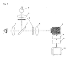
- Fig. 1 is a descriptive drawing of an example of the device of the present invention.
- visible light-cutting filters 3 are provided at two spots. However, in the actual device, such a filter is provided at only one of these two spots.
- visible light-cutting filter 3 is positioned between condenser lens 5 and beam splitter (half mirror) 2.
- visible light-cutting filter 3 is positioned between beam splitter (half mirror) 2 and image pickup lens 4. In both cases, in the course of passing through visible light-cutting filter 3, the visible light is cut out and at least a portion of the infrared rays is passed.
- light from a white light source 6 is condensed by a condenser lens 5.
- the condensed light then passes through visible light-cutting filter 3.
- the light that has passed through visible light-cutting filter 3 is reflected by a beam splitter (half mirror) 2, passes through objective lens 1, and reaches the meibomian glands of an eyelid that has been turned inside out, which constitute the site being observed.
- Light that has been irradiated onto and reflected off the meibomian glands sequentially passes through objective lens 1 and beam splitter (half mirror) 2, reaching infrared camera 7 via image pickup lens 4.
- light from a white light source 6 is condensed by a condenser lens 5.
- the condensed light is then reflected by a beam splitter (half mirror) 2, passes through objective lens 1, and reaches the meibomian glands of an eyelid that has been turned inside out, which constitute the site being observed.
- Light that has been irradiated onto and reflected off the meibomian glands sequentially passes through objective lens 1 and beam splitter (half mirror) 2. Next, it passes through visible light-cutting filter 3.
- the light that has passed through visible light-cutting filter 3 reaches infrared camera 7 of image pickup lens 4.
- visible light-cutting filter 3 can be positioned between beam splitter (half mirror) 2 and the site being observed.
- it can be positioned between beam splitter (half mirror) 2 and objective lens 1, or between objective lens 1 and the site being observed; the visible light can be cut from the light directed onto the meibomian glands or the light reflecting off the meibomian glands at any position prior to arrival at the infrared camera.
- an adapter 8, video recorder 9, and monitor 10 are connected to infrared camera 7.
- Adapter 8, video recorder 9, and monitor 10 are connected in series from infrared camera 7.
- at least video recorder 9 and monitor 10 can be connected in parallel from adapter 8.
- a slit device (slit aperture and slit aperture projection lens) can be present between condenser lens 5 and beam splitter (half mirror) 2.
- the slit device can be mounted on a common ophthalmologic diagnostic device.
- a slit device When a slit device is present, light that has been condensed by condenser lens 5 (in the device of the first aspect of the present invention, light that has passed through visible light-cutting filter 3) reaches beam splitter (half mirror) 2 after passing through the slit device.
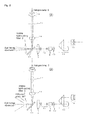
- Fig. 2 shows another aspect of the device of the present invention.
- Fig. 2 is a lateral view of the device.
- the device for observing the meibomian glands of the aspect shown in Fig. 2(A) comprises, in order from the light source side, a halogen lamp 6, condenser lens used for slit illumination system 18, slit aperture 17, slit aperture projection lens 16, deflecting mirror 11, and visible light-cutting filter 3.
- Light that has sequentially passed through is irradiated onto the object being observed (subject eye).
- Light reflecting off the object being observed passes through the periphery of deflecting mirror 11, and is subsequently sequentially transmitted to objective lens 1, variable power lens 12, beam splitter 2, and an infrared camera (not shown).
- a diffusion plate 30 can be provided to the side of the object being observed side of visible light-cutting filter 3. Providing a diffusion plate 30 affords the advantages of widening the illumination area and permitting observation of a broad range.
- the optical system for transmitting light from the light source to the site being observed can comprise an optical fiber.
- the optical system for transmitting light from the light source to the site being observed comprises an optical fiber
- light from the light source is condensed by a condenser lens and then introduced into the optical fiber.
- the exit of the optical fiber is positioned in the vicinity of the beam splitter (half mirror) or variable power lens.
- Light that has been guided by the optical fiber passes via the beam splitter (half mirror) or variable power lens (reflecting off the beam splitter (half mirror) or variable power lens) and reaches to meibomian glands of an eyelid that has been turned inside out, which is the site being observed.
- the visible light-cutting filter can be positioned, for example, on either the entry side or exit side of the optical fiber, and light that has been guided by the optical fiber can be passed through the visible light-cutting filter before being guided to the beam splitter (half mirror) or variable power lens.
- visible light-cutting filter 3 can be positioned, not on the exit side of the optical fiber, but between the beam splitter (half mirror) or variable power lens and the infrared camera.
- Fig. 3 shows a aspect of the device of the present invention comprising an optical fiber as the optical system for transmitting light from a light source to the site being observed.
- Fig. 3(A) is a lateral view of the device
- Fig. 3(B) is a plan view of the same.
- optical fiber 22 and a corresponding condensing lens 21 are employed to guide light for background illumination
- the configuration of the device is the same as that shown in Fig. 2 .
- the device for observing the meibomian glands of the aspect shown in Fig. 3 sequentially comprises, from the light source side, a halogen lamp 6, a condenser lens used for background illumination 21, a light guide used for background illumination 22, and a visible light-cutting filter 3.
- Visible light-cutting filter 3 can also be positioned on the entry side of light guide used for background illumination 22.
- the optical system for transmitting light from a light source to the site being observed may comprise both an optical system comprising an optical fiber as a light-guiding pathway (in which no slit device is present) and an optical system having the above-described slit device.
- an optical system containing optical fiber as a light-guiding pathway and an optical system having a slit device are both present, the portion of the site being observed that is illuminated with light is limited by the slit device in an optical system having a slit device.
- an advantage is afforded in that when light is illuminated via an optical system containing optical fiber as a light-guiding pathway, the illumination of a broader portion of the site being observed with light can be ensured than when a slit device is employed.
- the optical system comprising a slit device can be employed for applications other than observation of meibomian glands.
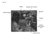
- Fig. 4 shows a photograph of an example of the observation device (meibography device) of the present invention.
- a slit lamp (RO5000, Rodenstock) that is widely employed in ophthalmologic medical examinations is utilized as the base.
- the light source and optical system of the slit lamp are employed, and a visible light-cutting filter (IR-83, Hoya) is installed in the vicinity of the light source (between the light source and the optical system for transmission to the site being observed).
- An infrared CCD video camera (XC-EI50, Sony) is installed forward of the optical system for transmitting light (infrared rays) reflecting off the site being observed to the infrared camera.
- a monitor for displaying the image (has been converted from infrared image to visible image) from the infrared CCD video camera (XC-EI50, Sony), a camera adapter (DC700, Sony), and a video cassette recorder (SVO-9500MD, DC-700, Sony) are also included.
- slit lamp refers to a microscope employed by ophthalmologists during medical examinations.
- a visible light-cutting filter passing 750 to 2,800 nm infrared light can be built into the illumination system of the slit lamp and the eyelid illuminated only by infrared rays.
- a small infrared CCD video camera was also installed above the slit lamp. The filter and camera made it possible to observe with infrared rays the meibomian glands, which were difficult to observe with the diffuse light of a normal slit lamp.
- the image from the infrared CCD video camera can be observed at a suitable magnification, for example.
- a suitable magnification for example.
- the image is observed on the screen of the monitor at 12-fold magnification.
- the contrast gain of the monitor and the magnification can be increased to observe in greater detail the acini of the meibomian glands of the pathologyically changed area.
- a video cassette recorder or the like can be used to record pictures of the meibomian glands of patients. When needed, they can be rewound on site and used to explain the pathosis to the patient.
- the first is that it can be readily assembled in any ophthalmologic clinic by mounting the above-described visible light-cutting filter, infrared CCD video camera, and monitor (and, as needed, camera adapter and video cassette recorder) on one of the slit lamps that are widely present and can be used by any ophthalmologist to medically examine patients.
- the visible light-cutting filter can be built into the same places and used in the same manner as a blue filter (when fluorescein dye solution is employed) for observing the keratoconjunctival epithelium and the stability of tears.
- a blue filter when fluorescein dye solution is employed
- the device for observing the meibomian glands is useful in the field of ophthalmologic examination devices.
Landscapes
- Life Sciences & Earth Sciences (AREA)
- Health & Medical Sciences (AREA)
- Medical Informatics (AREA)
- Biophysics (AREA)
- Ophthalmology & Optometry (AREA)
- Engineering & Computer Science (AREA)
- Biomedical Technology (AREA)
- Heart & Thoracic Surgery (AREA)
- Physics & Mathematics (AREA)
- Molecular Biology (AREA)
- Surgery (AREA)
- Animal Behavior & Ethology (AREA)
- General Health & Medical Sciences (AREA)
- Public Health (AREA)
- Veterinary Medicine (AREA)
- Eye Examination Apparatus (AREA)
Applications Claiming Priority (3)
| Application Number | Priority Date | Filing Date | Title |
|---|---|---|---|
| JP2007212030 | 2007-08-16 | ||
| JP2008118138 | 2008-04-30 | ||
| PCT/JP2008/064447 WO2009022692A1 (ja) | 2007-08-16 | 2008-08-12 | マイボーム腺観察装置 |
Publications (2)
| Publication Number | Publication Date |
|---|---|
| EP2189108A1 true EP2189108A1 (de) | 2010-05-26 |
| EP2189108A4 EP2189108A4 (de) | 2013-10-09 |
Family
ID=40350744
Family Applications (1)
| Application Number | Title | Priority Date | Filing Date |
|---|---|---|---|
| EP08827233.1A Pending EP2189108A4 (de) | 2007-08-16 | 2008-08-12 | Vorrichtung zur beobachtung der meibomdrüsen |
Country Status (4)
| Country | Link |
|---|---|
| US (1) | US20110273550A1 (de) |
| EP (1) | EP2189108A4 (de) |
| JP (1) | JP5281846B2 (de) |
| WO (1) | WO2009022692A1 (de) |
Cited By (14)
| Publication number | Priority date | Publication date | Assignee | Title |
|---|---|---|---|---|
| US7988294B2 (en) | 2007-06-20 | 2011-08-02 | Tearscience, Inc. | Tear film measurement |
| US8092023B2 (en) | 2009-04-01 | 2012-01-10 | Tearscience, Inc. | Ocular surface interferometry (OSI) methods for imaging and measuring ocular tear film layer thickness(es) |
| US8192026B2 (en) | 2007-06-20 | 2012-06-05 | Tearscience, Inc. | Tear film measurement |
| US8249695B2 (en) | 2006-09-29 | 2012-08-21 | Tearscience, Inc. | Meibomian gland imaging |
| US8255039B2 (en) | 2006-09-29 | 2012-08-28 | Tearscience, Inc. | Meibomian gland illuminating and imaging |
| CN102920427A (zh) * | 2012-11-09 | 2013-02-13 | 苏州四海通仪器有限公司 | 一种睑板腺成像系统 |
| US8888286B2 (en) | 2009-04-01 | 2014-11-18 | Tearscience, Inc. | Full-eye illumination ocular surface imaging of an ocular tear film for determining tear film thickness and/or providing ocular topography |
| US8915592B2 (en) | 2009-04-01 | 2014-12-23 | Tearscience, Inc. | Apparatuses and methods of ocular surface interferometry (OSI) employing polarization and subtraction for imaging, processing, and/or displaying an ocular tear film |
| US9339177B2 (en) | 2012-12-21 | 2016-05-17 | Tearscience, Inc. | Full-eye illumination ocular surface imaging of an ocular tear film for determining tear film thickness and/or providing ocular topography |
| US9642520B2 (en) | 2009-04-01 | 2017-05-09 | Tearscience, Inc. | Background reduction apparatuses and methods of ocular surface interferometry (OSI) employing polarization for imaging, processing, and/or displaying an ocular tear film |
| US9795290B2 (en) | 2013-11-15 | 2017-10-24 | Tearscience, Inc. | Ocular tear film peak detection and stabilization detection systems and methods for determining tear film layer characteristics |
| EP3275361A1 (de) * | 2016-07-29 | 2018-01-31 | Leica Instruments (Singapore) Pte. Ltd. | Medizinische abbildungsvorrichtung und verfahren zur abbildung eines lichtempfindlichen objekts wie z.b. biologischen gewebes |
| US9888839B2 (en) | 2009-04-01 | 2018-02-13 | Tearscience, Inc. | Methods and apparatuses for determining contact lens intolerance in contact lens wearer patients based on dry eye tear film characteristic analysis and dry eye symptoms |
| US10278587B2 (en) | 2013-05-03 | 2019-05-07 | Tearscience, Inc. | Eyelid illumination systems and method for imaging meibomian glands for meibomian gland analysis |
Families Citing this family (28)
| Publication number | Priority date | Publication date | Assignee | Title |
|---|---|---|---|---|
| US20090043365A1 (en) | 2005-07-18 | 2009-02-12 | Kolis Scientific, Inc. | Methods, apparatuses, and systems for reducing intraocular pressure as a means of preventing or treating open-angle glaucoma |
| US8083787B2 (en) | 2005-07-18 | 2011-12-27 | Tearscience, Inc. | Method and apparatus for treating meibomian gland dysfunction |
| US8950405B2 (en) | 2006-05-15 | 2015-02-10 | Tearscience, Inc. | Treatment of obstructive disorders of the eye or eyelid |
| US7981145B2 (en) | 2005-07-18 | 2011-07-19 | Tearscience Inc. | Treatment of meibomian glands |
| WO2013003594A2 (en) | 2011-06-28 | 2013-01-03 | Tearscience, Inc. | Methods and systems for treating meibomian gland dysfunction using radio-frequency energy |
| US7981095B2 (en) | 2005-07-18 | 2011-07-19 | Tearscience, Inc. | Methods for treating meibomian gland dysfunction employing fluid jet |
| US20070060988A1 (en) | 2005-07-18 | 2007-03-15 | Grenon Stephen M | Melting meibomian gland obstructions |
| US20080114423A1 (en) | 2006-05-15 | 2008-05-15 | Grenon Stephen M | Apparatus for inner eyelid treatment of meibomian gland dysfunction |
| US8128674B2 (en) | 2006-05-15 | 2012-03-06 | Tearscience, Inc. | System for outer eyelid heat and pressure treatment for treating meibomian gland dysfunction |
| US8128673B2 (en) | 2006-05-15 | 2012-03-06 | Tearscience, Inc. | System for inner eyelid heat and pressure treatment for treating meibomian gland dysfunction |
| US8137390B2 (en) | 2006-05-15 | 2012-03-20 | Tearscience, Inc. | System for providing heat treatment and heat loss reduction for treating meibomian gland dysfunction |
| US9314369B2 (en) | 2006-05-15 | 2016-04-19 | Tearscience, Inc. | System for inner eyelid treatment of meibomian gland dysfunction |
| JP5856385B2 (ja) | 2011-04-08 | 2016-02-09 | 株式会社トプコン | 眼科画像解析装置、及び眼科画像解析プログラム |
| JP5748268B2 (ja) * | 2011-04-25 | 2015-07-15 | 株式会社トプコン | マイボーム腺観察装置 |
| WO2014031857A2 (en) | 2012-08-22 | 2014-02-27 | Tearscience, Inc. | Apparatuses and methods for diagnosing and/or treating lipid transport deficiency in ocular tear films, and related components and devices |
| ES2821002T3 (es) | 2013-04-30 | 2021-04-23 | Alcon Inc | Sistemas para el tratamiento de enfermedades del ojo |
| US9763827B2 (en) | 2013-04-30 | 2017-09-19 | Tear Film Innovations, Inc. | Systems and methods for the treatment of eye conditions |
| CN103315707A (zh) * | 2013-06-24 | 2013-09-25 | 苏州视可佳医疗器械有限公司 | 睑板腺红外成像装置 |
| JP6456206B2 (ja) * | 2015-03-24 | 2019-01-23 | キヤノン株式会社 | 眼科装置、眼科装置の制御方法およびプログラム |
| JP6084649B2 (ja) * | 2015-04-13 | 2017-02-22 | 健一 ▲高▼木 | 眼瞼腫瘍性腫瘤性病変鑑別装置および眼瞼腫瘍性腫瘤性病変鑑別プログラム |
| US10974063B2 (en) | 2016-06-30 | 2021-04-13 | Alcon Inc. | Light therapy for eyelash growth |
| KR101755630B1 (ko) | 2016-07-22 | 2017-07-07 | 한림대학교 산학협력단 | 적외선 마이봄샘 촬영장치 |
| US11564563B2 (en) | 2018-02-17 | 2023-01-31 | Aizhong Zhang | Apparatus and method of a multifunctional ophthalmic instrument |
| CN108814545A (zh) * | 2018-03-14 | 2018-11-16 | 北京理工大学 | 一种与智能手机结合使用的免散瞳眼底相机 |
| JP7273394B2 (ja) | 2019-02-18 | 2023-05-15 | 株式会社トーメーコーポレーション | 眼科装置 |
| US11478145B2 (en) | 2019-05-15 | 2022-10-25 | Aizhong Zhang | Multispectral and hyperspectral meibography |
| US11253151B2 (en) | 2019-09-08 | 2022-02-22 | Aizhong Zhang | Multispectral and hyperspectral ocular surface evaluator |
| CN115299872A (zh) * | 2022-08-08 | 2022-11-08 | 中山大学中山眼科中心 | 结膜杯状细胞的荧光成像设备 |
Citations (2)
| Publication number | Priority date | Publication date | Assignee | Title |
|---|---|---|---|---|
| US20040156016A1 (en) * | 2001-04-09 | 2004-08-12 | Patrick Kerr | Retinal function camera |
| JP2004236727A (ja) * | 2003-02-04 | 2004-08-26 | Naitsu:Kk | マイボーム腺の観察装置 |
Family Cites Families (26)
| Publication number | Priority date | Publication date | Assignee | Title |
|---|---|---|---|---|
| JPH04132534A (ja) * | 1990-09-25 | 1992-05-06 | Topcon Corp | 眼科撮影装置 |
| US5400791A (en) * | 1991-10-11 | 1995-03-28 | Candela Laser Corporation | Infrared fundus video angiography system |
| DE4320579C2 (de) * | 1992-06-15 | 2000-06-15 | Topcon Corp | Operationsmikroskop |
| US5349398A (en) * | 1992-07-17 | 1994-09-20 | The Trustees Of Columbia University In The City Of New York | Ophthalmometer system |
| JPH07124119A (ja) * | 1993-10-26 | 1995-05-16 | Canon Inc | 眼科装置 |
| JP3408308B2 (ja) * | 1994-02-02 | 2003-05-19 | 株式会社ニデック | 眼底カメラ |
| US6032070A (en) * | 1995-06-07 | 2000-02-29 | University Of Arkansas | Method and apparatus for detecting electro-magnetic reflection from biological tissue |
| US5886767A (en) * | 1996-10-09 | 1999-03-23 | Snook; Richard K. | Keratometry system and method for measuring physical parameters of the cornea |
| US6553138B2 (en) * | 1998-12-30 | 2003-04-22 | New York University | Method and apparatus for generating three-dimensional representations of objects |
| DE29901791U1 (de) * | 1999-02-02 | 2000-07-06 | Novartis Ag, Basel | Linsenmesseinrichtung |
| JP3660193B2 (ja) * | 2000-03-22 | 2005-06-15 | 株式会社ニデック | 眼底カメラ |
| CN1285943C (zh) * | 2001-12-12 | 2006-11-22 | 株式会社尼康 | 具有波长选择装置的光学系统 |
| US6847443B1 (en) * | 2002-01-17 | 2005-01-25 | Rudolph Technologies, Inc. | System and method for multi-wavelength, narrow-bandwidth detection of surface defects |
| EP1485011B1 (de) * | 2002-03-12 | 2013-02-13 | Beth Israel Deaconess Medical Center | Medizinische bildgebungssysteme |
| JP2003310553A (ja) * | 2002-04-22 | 2003-11-05 | Nippon Syst Design Kk | 対光反射検査カメラ |
| JP2004329879A (ja) * | 2003-02-07 | 2004-11-25 | Nippon Syst Design Kk | 眼球検査装置及び眼球検査方法 |
| JP2004254945A (ja) * | 2003-02-26 | 2004-09-16 | Nidek Co Ltd | 眼底カメラ |
| JP4408640B2 (ja) * | 2003-03-17 | 2010-02-03 | 興和株式会社 | 眼科測定装置 |
| US20050082480A1 (en) * | 2003-08-26 | 2005-04-21 | Aegis Semiconductor, Inc. | Infrared camera system |
| US20070027362A1 (en) * | 2005-07-27 | 2007-02-01 | Olympus Medical Systems Corp. | Infrared observation system |
| DE102006004232C5 (de) * | 2006-01-30 | 2013-08-01 | Carl Zeiss Surgical Gmbh | Mikroskopiesystem |
| JP2007212030A (ja) | 2006-02-08 | 2007-08-23 | Koyo Thermo System Kk | 熱処理装置 |
| US8249695B2 (en) * | 2006-09-29 | 2012-08-21 | Tearscience, Inc. | Meibomian gland imaging |
| DE602006014551D1 (de) | 2006-10-31 | 2010-07-08 | Soitec Silicon On Insulator | Verfahren zur Charakterisierung von Defekten auf Silizium-Oberflächen, Ätzlösung für Silizium-Oberflächen und Verfahren zur Behandlung von Silizium-Oberflächen mit der Ätzlösung |
| JP5031405B2 (ja) * | 2007-03-02 | 2012-09-19 | キヤノン株式会社 | 眼科撮影装置、眼科撮影装置の制御方法およびプログラム |
| WO2011029064A1 (en) * | 2009-09-04 | 2011-03-10 | University Of Virginia Patent Foundation | Hand-held portable fundus camera for screening photography |
-
2008
- 2008-08-12 EP EP08827233.1A patent/EP2189108A4/de active Pending
- 2008-08-12 WO PCT/JP2008/064447 patent/WO2009022692A1/ja active Application Filing
- 2008-08-12 US US12/673,505 patent/US20110273550A1/en not_active Abandoned
- 2008-08-18 JP JP2008210103A patent/JP5281846B2/ja active Active
Patent Citations (2)
| Publication number | Priority date | Publication date | Assignee | Title |
|---|---|---|---|---|
| US20040156016A1 (en) * | 2001-04-09 | 2004-08-12 | Patrick Kerr | Retinal function camera |
| JP2004236727A (ja) * | 2003-02-04 | 2004-08-26 | Naitsu:Kk | マイボーム腺の観察装置 |
Non-Patent Citations (1)
| Title |
|---|
| See also references of WO2009022692A1 * |
Cited By (38)
| Publication number | Priority date | Publication date | Assignee | Title |
|---|---|---|---|---|
| US8600484B2 (en) | 2006-09-29 | 2013-12-03 | Tearscience, Inc. | Meibomian gland imaging |
| US8249695B2 (en) | 2006-09-29 | 2012-08-21 | Tearscience, Inc. | Meibomian gland imaging |
| US8255039B2 (en) | 2006-09-29 | 2012-08-28 | Tearscience, Inc. | Meibomian gland illuminating and imaging |
| US8585204B2 (en) | 2007-06-20 | 2013-11-19 | Tearscience, Inc. | Tear film measurement |
| US7988294B2 (en) | 2007-06-20 | 2011-08-02 | Tearscience, Inc. | Tear film measurement |
| US8192026B2 (en) | 2007-06-20 | 2012-06-05 | Tearscience, Inc. | Tear film measurement |
| US8591033B2 (en) | 2007-06-20 | 2013-11-26 | Tearscience, Inc. | Tear film measurement |
| US9693682B2 (en) | 2009-04-01 | 2017-07-04 | Tearscience, Inc. | Ocular surface interferometry (OSI) devices and systems for imaging, processing, and/or displaying an ocular tear film |
| US9888839B2 (en) | 2009-04-01 | 2018-02-13 | Tearscience, Inc. | Methods and apparatuses for determining contact lens intolerance in contact lens wearer patients based on dry eye tear film characteristic analysis and dry eye symptoms |
| US11771317B2 (en) | 2009-04-01 | 2023-10-03 | Tearscience, Inc. | Ocular surface interferometry (OSI) for imaging, processing, and/or displaying an ocular tear film |
| US8215774B2 (en) | 2009-04-01 | 2012-07-10 | Tearscience, Inc. | Ocular surface interferometry (OSI) devices and systems for imaging and measuring ocular tear film layer thickness(es) |
| US8746883B2 (en) | 2009-04-01 | 2014-06-10 | Tearscience, Inc. | Ocular surface interferometery (OSI) devices and systems for imaging, processing, and/or displaying an ocular tear film |
| US8888286B2 (en) | 2009-04-01 | 2014-11-18 | Tearscience, Inc. | Full-eye illumination ocular surface imaging of an ocular tear film for determining tear film thickness and/or providing ocular topography |
| US8915592B2 (en) | 2009-04-01 | 2014-12-23 | Tearscience, Inc. | Apparatuses and methods of ocular surface interferometry (OSI) employing polarization and subtraction for imaging, processing, and/or displaying an ocular tear film |
| US11259700B2 (en) | 2009-04-01 | 2022-03-01 | Tearscience Inc | Ocular surface interferometry (OSI) for imaging, processing, and/or displaying an ocular tear film |
| US9642520B2 (en) | 2009-04-01 | 2017-05-09 | Tearscience, Inc. | Background reduction apparatuses and methods of ocular surface interferometry (OSI) employing polarization for imaging, processing, and/or displaying an ocular tear film |
| US9662008B2 (en) | 2009-04-01 | 2017-05-30 | Tearscience, Inc. | Ocular surface interferometry (OSI) devices and systems for imaging, processing, and/or displaying an ocular tear film |
| US10716465B2 (en) | 2009-04-01 | 2020-07-21 | Johnson & Johnson Vision Care, Inc. | Methods and apparatuses for determining contact lens intolerance in contact lens wearer patients based on dry eye tear film characteristic analysis and dry eye symptoms |
| US8092023B2 (en) | 2009-04-01 | 2012-01-10 | Tearscience, Inc. | Ocular surface interferometry (OSI) methods for imaging and measuring ocular tear film layer thickness(es) |
| US10582848B2 (en) | 2009-04-01 | 2020-03-10 | Tearscience, Inc. | Ocular surface interferometry (OSI) devices and systems for imaging, processing, and/or displaying an ocular tear film |
| US10004396B2 (en) | 2009-04-01 | 2018-06-26 | Tearscience, Inc. | Ocular surface interferometry (OSI) devices and systems for imaging, processing, and/or displaying an ocular tear film |
| US9999346B2 (en) | 2009-04-01 | 2018-06-19 | Tearscience, Inc. | Background reduction apparatuses and methods of ocular surface interferometry (OSI) employing polarization for imaging, processing, and/or displaying an ocular tear film |
| US8545017B2 (en) | 2009-04-01 | 2013-10-01 | Tearscience, Inc. | Ocular surface interferometry (OSI) methods for imaging, processing, and/or displaying an ocular tear film |
| CN102920427A (zh) * | 2012-11-09 | 2013-02-13 | 苏州四海通仪器有限公司 | 一种睑板腺成像系统 |
| US9668647B2 (en) | 2012-12-21 | 2017-06-06 | Tearscience Inc. | Full-eye illumination ocular surface imaging of an ocular tear film for determining tear film thickness and/or providing ocular topography |
| US9993151B2 (en) | 2012-12-21 | 2018-06-12 | Tearscience, Inc. | Full-eye illumination ocular surface imaging of an ocular tear film for determining tear film thickness and/or providing ocular topography |
| US10244939B2 (en) | 2012-12-21 | 2019-04-02 | Tearscience, Inc. | Full-eye illumination ocular surface imaging of an ocular tear film for determining tear film thickness and/or providing ocular topography |
| US9339177B2 (en) | 2012-12-21 | 2016-05-17 | Tearscience, Inc. | Full-eye illumination ocular surface imaging of an ocular tear film for determining tear film thickness and/or providing ocular topography |
| US10582849B2 (en) | 2012-12-21 | 2020-03-10 | Tearscience, Inc. | Full-eye illumination ocular surface imaging of an ocular tear film for determining tear film thickness and/or providing ocular topography |
| US10278587B2 (en) | 2013-05-03 | 2019-05-07 | Tearscience, Inc. | Eyelid illumination systems and method for imaging meibomian glands for meibomian gland analysis |
| US11844586B2 (en) | 2013-05-03 | 2023-12-19 | Tearscience, Inc. | Eyelid illumination systems and methods for imaging meibomian glands for meibomian gland analysis |
| US11141065B2 (en) | 2013-05-03 | 2021-10-12 | Tearscience, Inc | Eyelid illumination systems and methods for imaging meibomian glands for meibomian gland analysis |
| US10512396B2 (en) | 2013-11-15 | 2019-12-24 | Tearscience, Inc. | Ocular tear film peak detection and stabilization detection systems and methods for determining tear film layer characteristics |
| US9795290B2 (en) | 2013-11-15 | 2017-10-24 | Tearscience, Inc. | Ocular tear film peak detection and stabilization detection systems and methods for determining tear film layer characteristics |
| CN107661087B (zh) * | 2016-07-29 | 2019-12-31 | 徕卡仪器(新加坡)有限公司 | 用于感光物体如生物组织的成像的医学成像装置及方法 |
| US11501427B2 (en) | 2016-07-29 | 2022-11-15 | Leica Instruments (Singapore) Pte. Ltd. | Medical imaging apparatus and method for the imaging of a light-sensitive object, such as biological tissue |
| CN107661087A (zh) * | 2016-07-29 | 2018-02-06 | 徕卡仪器(新加坡)有限公司 | 用于感光物体如生物组织的成像的医学成像装置及方法 |
| EP3275361A1 (de) * | 2016-07-29 | 2018-01-31 | Leica Instruments (Singapore) Pte. Ltd. | Medizinische abbildungsvorrichtung und verfahren zur abbildung eines lichtempfindlichen objekts wie z.b. biologischen gewebes |
Also Published As
| Publication number | Publication date |
|---|---|
| US20110273550A1 (en) | 2011-11-10 |
| WO2009022692A1 (ja) | 2009-02-19 |
| JP5281846B2 (ja) | 2013-09-04 |
| JP2009285447A (ja) | 2009-12-10 |
| EP2189108A4 (de) | 2013-10-09 |
Similar Documents
| Publication | Publication Date | Title |
|---|---|---|
| EP2189108A1 (de) | Vorrichtung zur beobachtung der meibomdrüsen | |
| US6350031B1 (en) | Electro-optic binocular indirect ophthalmoscope | |
| EP1809162B1 (de) | Optisches gerät und verfahren zur umfassenden augendiagnose | |
| AU2007254999B2 (en) | Laser scanning digital camera with simplified optics and potential for multiply scattered light imaging | |
| US6761455B2 (en) | Ophthalmic apparatus | |
| JPS6223570B2 (de) | ||
| WO2019146792A1 (ja) | 近接撮影用装置 | |
| JP2001258847A (ja) | 眼底カメラ | |
| JP2003047595A (ja) | 眼科撮影装置 | |
| JP4850561B2 (ja) | 眼科装置 | |
| JP3743469B2 (ja) | 細隙灯顕微鏡 | |
| JP2005323815A (ja) | 眼科検査装置 | |
| JP2004024470A (ja) | 眼科撮影装置 | |
| WO2019100449A1 (zh) | 一种基于传像光纤的手术导航系统 | |
| JPH05344997A (ja) | 医用実体顕微鏡 | |
| KR100796355B1 (ko) | 근적외선을 이용한 세극등 검사장치 | |
| JP3332489B2 (ja) | 検眼装置 | |
| JPS6057855B2 (ja) | 眼底カメラ | |
| JP3809267B2 (ja) | 眼科撮影装置 | |
| JPH10192244A (ja) | 眼科装置 | |
| JPS6057854B2 (ja) | 固視目標を有する眼底カメラ | |
| JPH11206711A (ja) | 検眼装置 | |
| JPH09140672A (ja) | 眼底カメラ | |
| JPH09187427A (ja) | 眼内観察装置 | |
| JPH1176166A (ja) | 眼底撮影装置 |
Legal Events
| Date | Code | Title | Description |
|---|---|---|---|
| PUAI | Public reference made under article 153(3) epc to a published international application that has entered the european phase |
Free format text: ORIGINAL CODE: 0009012 |
|
| 17P | Request for examination filed |
Effective date: 20100312 |
|
| AK | Designated contracting states |
Kind code of ref document: A1 Designated state(s): AT BE BG CH CY CZ DE DK EE ES FI FR GB GR HR HU IE IS IT LI LT LU LV MC MT NL NO PL PT RO SE SI SK TR |
|
| AX | Request for extension of the european patent |
Extension state: AL BA MK RS |
|
| DAX | Request for extension of the european patent (deleted) | ||
| A4 | Supplementary search report drawn up and despatched |
Effective date: 20130905 |
|
| RIC1 | Information provided on ipc code assigned before grant |
Ipc: A61B 3/10 20060101AFI20130830BHEP |
|
| RAP1 | Party data changed (applicant data changed or rights of an application transferred) |
Owner name: ARITA, REIKO Owner name: KAMOTO, YOSHINORI |
|
| RIN1 | Information on inventor provided before grant (corrected) |
Inventor name: KAMOTO, YOSHINORI Inventor name: AMANO, SHIRO Inventor name: ARITA, REIKO |
|
| STAA | Information on the status of an ep patent application or granted ep patent |
Free format text: STATUS: EXAMINATION IS IN PROGRESS |
|
| 17Q | First examination report despatched |
Effective date: 20180221 |
|
| STAA | Information on the status of an ep patent application or granted ep patent |
Free format text: STATUS: EXAMINATION IS IN PROGRESS |
|
| STAA | Information on the status of an ep patent application or granted ep patent |
Free format text: STATUS: EXAMINATION IS IN PROGRESS |