EP2171732B1 - Stromkompensierte drossel und schaltungsanordnung mit einer stromkompensierten drossel - Google Patents
Stromkompensierte drossel und schaltungsanordnung mit einer stromkompensierten drossel Download PDFInfo
- Publication number
- EP2171732B1 EP2171732B1 EP08774383.7A EP08774383A EP2171732B1 EP 2171732 B1 EP2171732 B1 EP 2171732B1 EP 08774383 A EP08774383 A EP 08774383A EP 2171732 B1 EP2171732 B1 EP 2171732B1
- Authority
- EP
- European Patent Office
- Prior art keywords
- current
- windings
- core
- compensated inductor
- compensated
- Prior art date
- Legal status (The legal status is an assumption and is not a legal conclusion. Google has not performed a legal analysis and makes no representation as to the accuracy of the status listed.)
- Active
Links
Images
Classifications
-
- H—ELECTRICITY
- H01—ELECTRIC ELEMENTS
- H01F—MAGNETS; INDUCTANCES; TRANSFORMERS; SELECTION OF MATERIALS FOR THEIR MAGNETIC PROPERTIES
- H01F19/00—Fixed transformers or mutual inductances of the signal type
- H01F19/04—Transformers or mutual inductances suitable for handling frequencies considerably beyond the audio range
- H01F19/08—Transformers having magnetic bias, e.g. for handling pulses
-
- H—ELECTRICITY
- H01—ELECTRIC ELEMENTS
- H01F—MAGNETS; INDUCTANCES; TRANSFORMERS; SELECTION OF MATERIALS FOR THEIR MAGNETIC PROPERTIES
- H01F17/00—Fixed inductances of the signal type
- H01F17/04—Fixed inductances of the signal type with magnetic core
- H01F17/045—Fixed inductances of the signal type with magnetic core with core of cylindric geometry and coil wound along its longitudinal axis, i.e. rod or drum core
-
- H—ELECTRICITY
- H01—ELECTRIC ELEMENTS
- H01F—MAGNETS; INDUCTANCES; TRANSFORMERS; SELECTION OF MATERIALS FOR THEIR MAGNETIC PROPERTIES
- H01F27/00—Details of transformers or inductances, in general
- H01F27/02—Casings
-
- H—ELECTRICITY
- H01—ELECTRIC ELEMENTS
- H01F—MAGNETS; INDUCTANCES; TRANSFORMERS; SELECTION OF MATERIALS FOR THEIR MAGNETIC PROPERTIES
- H01F5/00—Coils
-
- H—ELECTRICITY
- H01—ELECTRIC ELEMENTS
- H01F—MAGNETS; INDUCTANCES; TRANSFORMERS; SELECTION OF MATERIALS FOR THEIR MAGNETIC PROPERTIES
- H01F17/00—Fixed inductances of the signal type
- H01F2017/0093—Common mode choke coil
-
- H—ELECTRICITY
- H01—ELECTRIC ELEMENTS
- H01F—MAGNETS; INDUCTANCES; TRANSFORMERS; SELECTION OF MATERIALS FOR THEIR MAGNETIC PROPERTIES
- H01F27/00—Details of transformers or inductances, in general
- H01F27/34—Special means for preventing or reducing unwanted electric or magnetic effects, e.g. no-load losses, reactive currents, harmonics, oscillations, leakage fields
- H01F27/346—Preventing or reducing leakage fields
-
- H—ELECTRICITY
- H01—ELECTRIC ELEMENTS
- H01F—MAGNETS; INDUCTANCES; TRANSFORMERS; SELECTION OF MATERIALS FOR THEIR MAGNETIC PROPERTIES
- H01F27/00—Details of transformers or inductances, in general
- H01F27/34—Special means for preventing or reducing unwanted electric or magnetic effects, e.g. no-load losses, reactive currents, harmonics, oscillations, leakage fields
- H01F27/38—Auxiliary core members; Auxiliary coils or windings
- H01F27/385—Auxiliary core members; Auxiliary coils or windings for reducing harmonics
-
- H—ELECTRICITY
- H01—ELECTRIC ELEMENTS
- H01F—MAGNETS; INDUCTANCES; TRANSFORMERS; SELECTION OF MATERIALS FOR THEIR MAGNETIC PROPERTIES
- H01F37/00—Fixed inductances not covered by group H01F17/00
Definitions
- It describes a current-compensated choke with at least two arranged on a common core windings, which can be traversed by the current so that cancel their magnetic fields.
- An object to be solved is to specify a throttle in which the most complete possible cancellation of magnetic fields and the smallest possible resistance is achieved.
- a current-compensated choke which has a plurality of current paths, each of these current paths having a plurality of parallel-connected windings.
- the windings are wound on a common core.
- the current paths are provided for opposite current directions.
- the use of the throttle is also possible if the current paths have current directions in the same direction.
- the windings are preferably chosen so that the magnetic fields generated by the current paths cancel each other out.
- the individual windings preferably each form a complete layer around the core, the layer covering the core as completely as possible in the longitudinal direction.
- the individual layers of windings form an array of multiple layers disposed about the core.
- the windings belonging to different current paths are preferably arranged alternately one above the other on the core.
- Windings belonging to a common current path are preferably not wound directly over one another on the core. For example, located over a first winding of a first current path, a first winding of a second current path, followed by the second winding of the first current path and in turn followed by the second winding of the second current path.
- This arrangement corresponds approximately to a bifilar winding arrangement, which supports an almost complete cancellation of the magnetic fields of the windings belonging to the current paths. As a result, both a reduction in the leakage inductance of the throttle and an improvement in the quality of the throttle is achieved.
- the windings are arranged so that windings which belong to the same current path are preferably not wound directly above or below one another on the core.
- the core is preferably a rod-shaped core. This contains according to an embodiment ferromagnetic material.
- the windings on the core are preferably arranged such that the magnetic fields generated by the current paths at least largely compensate each other. With opposite current paths, all windings preferably have the same winding sense. As a result, the magnetic fields generated by the current flowing in the opposite direction cancel each other out. In the case of corotating current paths, the windings belonging to the respective current paths have a different winding sense.
- the arrangement of the windings belonging to the current paths are preferably arranged in such a way that the magnetic fields generated by the current paths cancel each other out.
- the windings on the core are largely surrounded by a cap. This leads to a further reduction of the leakage inductance.
- only one cover plate can be provided, which rests on the windings.
- a cap or a plate causes an improvement of the magnetic closure of the field lines.
- the leakage inductance is reduced.
- the number of turns can be reduced with the same inductance by the improved conclusion, so that in addition the ohmic resistance can be reduced.
- using a cap or Cover plate creates a small air gap, the structure comes closer to an ideal toroidal core choke.
- the throttle has a plurality of external contacts, wherein in each case two external contacts for contacting the reactor are provided for each current path and the current paths are electrically conductively connected to the external contacts.
- the current-compensated choke is preferably used in a circuit arrangement in which the current-compensated choke is inserted in the data lines of a data bus.
- the first current path of the inductor is connected to a first conductor of the data line
- the second current path of the inductor is connected in series with a second conductor of the data line.
- the ends of a first current path of the choke are connected to a first conductor of a data line and the ends of a second current path are connected to a second conductor of a data line.
- the electrical conductors of the data line are exposed to an electromagnetic interference source, so that the current flowing through the electrical conductors of the data line does not have the same current intensity in different directions.
- the throttle is preferably connected to data conductors or to a bus system.
- the data conductors may be part of a control or communication network in a motor vehicle. These are preferably CAN bus systems or FlexRay bus systems in which the circuit arrangement can be used.
- the choke is suitable for other data transfer bus systems in which narrow limits in leakage inductance and DC resistance play a role.
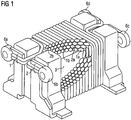
- FIG. 1 a current-compensated choke is shown in which a plurality of windings 1a, 1b, 2a, 2b are wound around a common core 3.
- the core 3 is preferably rod-shaped and has ferromagnetic material.
- the throttle has at its two end faces a plurality of external contacts 6a, 6b, 6c, 6d, at each of which two of the windings 1a, 1b, 2a, 2b, which are connected in parallel to a common current path 1, 2, are electrically contacted.
- windings 1a, 1b, 2a, 2b are preferably wound up alternately on the core 3, so that directly superimposed windings 1a, 1b, 2a, 2b do not belong to one and the same current path 1, 2.
- the individual layers of the windings 1a, 1b, 2a, 2b are arranged laterally offset from each other.
- each winding 1a, 1b, 2a, 2b of each layer could come to lie in the intermediate space between two windings 1a, 1b, 2a, 2b of an adjacent layer and at least partially fill this intermediate space.
- a space-saving design is offered, in which the leakage inductance can be reduced.
- the windings 1a, 1b, 2a, 2b are arranged so that windings 1a, 1b, 2a, 2b, which are assigned to a common current path 1, 2, preferably do not lie directly above one another.
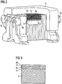
- one possible embodiment of the choke is shown having a cap 4 which at least for the most part surrounds the wrapped core 3.
- a cover plate may be provided on the wrapped core.
- FIG. 3 shows a schematic representation of the windings 1a, 1b, 2a, 2b around the core 3.
- the windings 1a, 1b, 2a, 2b are shown as layers. It should thus be shown the order of the windings 1a, 1b, 2a, 2b.
- the arrangement of the individual windings described above makes it possible to achieve a leakage inductance which meets the required specifications, for example for bus systems in motor vehicles.
- the optimization is done here only in terms of leakage inductance.
- a combination of the first winding with the fourth winding and a combination of the second winding with the third winding would be best, but the effect of the low leakage inductance would be lost.
Landscapes
- Engineering & Computer Science (AREA)
- Power Engineering (AREA)
- Microelectronics & Electronic Packaging (AREA)
- Multimedia (AREA)
- Coils Or Transformers For Communication (AREA)
- Coils Of Transformers For General Uses (AREA)
- Power Conversion In General (AREA)
Description
- Es wird eine stromkompensierte Drossel mit wenigstens zwei auf einem gemeinsamen Kern angeordneten Wicklungen beschrieben, die vom Strom so durchflossen werden kann, dass sich deren magnetischen Felder aufheben.
- Aus der Druckschrift
DE 26 00 765 A1 ist eine stromkompensierte Drossel bekannt. In derUS 5,521,573 A wird eine Spule mit mehreren gedruckten, übereinander liegenden Leitern gezeigt. DieUS 2,535,554 A zeigt einen Transformator mit gestanzten Wicklungen. - Eine zu lösende Aufgabe besteht darin, eine Drossel anzugeben, bei der eine möglichst vollständige Aufhebung von magnetischen Feldern und ein möglichst kleiner Widerstand erreicht wird.
- Es wird eine stromkompensierte Drossel angegeben, welche mehrere Strompfade aufweist, wobei jeder dieser Strompfade mehrere parallel geschaltete Wicklungen aufweist. Die Wicklungen sind auf einem gemeinsamen Kern aufgewickelt. Vorzugsweise sind die Strompfade für gegenläufige Stromrichtungen vorgesehen. Der Einsatz der Drossel ist auch möglich, wenn die Strompfade gleichläufige Stromrichtungen aufweisen. Die Wicklungen werden vorzugsweise so gewählt, dass sich die durch die Strompfade erzeugten magnetischen Felder aufheben.
- Durch die Parallelschaltung von mehreren Wicklungen zu einem gemeinsamen Strompfad können kleine Widerstandswerte erreicht werden, die in bestimmten Anwendungsbereichen, wie beispielsweise in Datenbussystemen, erforderlich sind.
- Die einzelnen Wicklungen bilden bevorzugt jeweils eine vollständige Lage um den Kern, wobei die Lage den Kern in Längsrichtung möglichst vollständig abdeckt.
- Nach einer Ausführungsform bilden somit die einzelnen Lagen der Wicklungen eine Anordnung von mehreren Schichten, die um den Kern angeordnet sind.
- Die zu unterschiedlichen Strompfaden gehörenden Wicklungen sind bevorzugt alternierend übereinander auf dem Kern angeordnet.
- Wicklungen, die zu einem gemeinsamen Strompfad gehören, sind bevorzugt nicht direkt übereinander auf dem Kern aufgewickelt. Beispielsweise befindet sich über einer ersten Wicklung eines ersten Strompfades eine erste Wicklung eines zweiten Strompfades, gefolgt von der zweiten Wicklung des ersten Strompfades und wiederum gefolgt von der zweiten Wicklung des zweiten Strompfades. Diese Anordnung entspricht näherungsweise einer bifilaren Wickelanordnung, die eine nahezu vollständige Aufhebung der Magnetfelder der zu den Strompfaden gehörenden Wicklungen unterstützt. Dadurch wird sowohl eine Minderung der Streuinduktivität der Drossel als auch eine Verbesserung der Qualität der Drossel erreicht.
- Bei mehr als zwei Strompfaden sind die Wicklungen so angeordnet, dass Wicklungen, die zu einem gleichen Strompfad gehören, vorzugsweise nicht direkt über- bzw. untereinander auf dem Kern aufgewickelt sind.
- Bei dem Kern handelt es sich vorzugsweise um einen stabförmigen Kern. Dieser enthält gemäß einer Ausführungsform ferromagnetisches Material.
- Die Wicklungen auf dem Kern sind vorzugsweise derart angeordnet, dass sich die durch die Strompfade erzeugten magnetischen Felder zumindest größtenteils gegenseitig kompensieren. Bei gegenläufigen Strompfaden weisen alles Wicklungen bevorzugt den gleichen Wickelsinn auf. Dadurch heben sich die durch den in gegenläufiger Richtung fließenden Strom erzeugten magnetischen Felder auf. Bei gleichläufigen Strompfaden weisen die zu den jeweiligen Strompfaden gehörenden Wicklungen einen unterschiedlichen Wickelsinn auf. Die Anordnung der zu den Strompfaden gehörenden Wicklungen sind vorzugsweise in der Art angeordnet, so dass sich die von den Strompfaden erzeugten magnetischen Felder gegenseitig aufheben.
- In einer Ausführungsform sind die Wicklungen auf dem Kern größtenteils von einer Kappe umgeben. Dies führt zu einer weiteren Verringerung der Streuinduktivität.
- In einer weiteren Ausführungsform kann anstelle der Kappe auch nur eine Abdeckplatte vorgesehen sein, die auf den Wicklungen aufliegt.
- Eine Kappe oder eine Platte bewirken eine Verbesserung des magnetischen Schlusses der Feldlinien. Durch die Verbesserung des magnetischen Schlusses reduziert sich die Streuinduktivität. Weiterhin kann durch den verbesserten Schluss die Anzahl der Windungen bei gleicher Induktivität verringert werden, so dass zusätzlich der ohmsche Widerstand reduziert werden kann. Obwohl bei Verwendung einer Kappe oder Abdeckplatte ein kleiner Luftspalt entsteht, kommt der Aufbau dadurch näher an ein ideale Ringkerndrossel.
- Bevorzugt weist die Drossel mehrere Außenkontakte auf, wobei für jeden Strompfad jeweils zwei Außenkontakte zur Kontaktierung der Drossel vorgesehen sind und die Strompfade mit den Außenkontakten elektrisch leitend verbunden sind.
- Durch die besondere Anordnung der Wicklungen, die zu den Strompfaden gehören, wird auf Grund des Verhältnisses der Länge der einzelnen Wicklungen ein annähernd gleicher Widerstand der Strompfade erreicht. Durch die alternierend angeordneten Wicklungen wird, bei sich aufhebenden Magnetfeldern, somit eine minimale Streuinduktivität erreicht.
- Die stromkompensierte Drossel findet vorzugsweise in einer Schaltungsanordnung Verwendung, bei der die stromkompensierte Drossel in die Datenleitungen eines Datenbusses eingefügt ist. Der erste Strompfad der Drossel ist mit einem ersten Leiter der Datenleitung, der zweite Strompfad der Drossel ist mit einem zweiten Leiter der Datenleitung in Reihe geschaltet. Bei der stromkompensierten Drossel sind die Enden eines ersten Strompfades der Drossel an einen ersten Leiter einer Datenleitung angeschlossen und die Enden eines zweiten Strompfades an einen zweiten Leiter einer Datenleitung angeschlossen. Die elektrischen Leiter der Datenleitung sind einer elektromagnetischen Störquelle ausgesetzt, so dass der durch die elektrischen Leiter der Datenleitung fließende Strom, bei unterschiedlicher Richtung, nicht die gleiche Stromstärke aufweist.
- In der Schaltungsanordnung ist die Drossel vorzugsweise mit Datenleitern bzw. mit einem Bussystem verbunden. Die Datenleiter können Bestandteil eines Kontroll- bzw. Kommunikationsnetzwerkes in einem Kraftfahrzeugs sein. Bei solchen handelt es sich vorzugsweise um CAN-Bussysteme oder FlexRay-Bussysteme, in denen die Schaltungsanordnung Verwendung finden kann.
- Des Weiteren ist die Drossel für andere Bussysteme zur Datenübertragung geeignet, bei denen enge Grenzen hinsichtlich der Streuinduktivität und des DC-Widerstands eine Rolle spielen.
- Die beschriebenen Gegenstände werden anhand der folgenden Figuren und Ausführungsbeispiele näher erläutert.
- Die nachfolgend beschriebenen Zeichnungen sind nicht als maßstabsgetreu aufzufassen. Vielmehr können zur besseren Darstellung einzelne Dimensionen vergrößert, verkleinert oder auch verzerrt dargestellt sein.
- Elemente, die einander gleichen oder die die gleiche Funktion übernehmen, sind mit gleichen Bezugszeichen bezeichnet.
- Figur 1
- zeigt eine erste Ausführungsform der stromkompensierten Drossel,
- Figur 2
- zeigt eine weitere Ausführungsform der stromkompensierten Drossel mit aufgesetzter Kappe,
- Figur 3
- zeigt eine schematische Darstellung der Wicklungen um den Kern der stromkompensierten Drossel.
- In
Figur 1 ist eine stromkompensierte Drossel gezeigt, bei der mehrere Wicklungen 1a, 1b, 2a, 2b um einen gemeinsamen Kern 3 gewickelt sind. Der Kern 3 ist vorzugsweise stabförmig und weist ferromagnetisches Material auf. - Die Drossel weist an ihren beiden Stirnseiten mehrere Außenkontakte 6a, 6b, 6c, 6d auf, an denen jeweils zwei der Wicklungen 1a, 1b, 2a, 2b, die zu einem gemeinsamen Strompfad 1, 2 parallel geschaltet sind, elektrisch kontaktiert sind.
- Die Wicklungen 1a, 1b, 2a, 2b sind vorzugsweise alternierend auf den Kern 3 aufgewickelt, sodass direkt übereinander liegende Wicklungen 1a, 1b, 2a, 2b nicht zu ein und demselben Strompfad 1, 2 gehören.
- Es ergibt sich somit eine Reihenfolge, die mit einer ersten Wicklung 1a eines ersten Strompfades 1 beginnt. Auf diese folgt eine erste Wicklung 2a eines zweiten Strompfades 2, gefolgt von der zweiten Wicklung 1b des ersten Strompfades 1. Den Abschluss bildet die zweite Wicklung 2b des zweiten Strompfades 2.
- Gemäß einer Ausführungsform sind die einzelnen Lagen der Wicklungen 1a, 1b, 2a, 2b zueinander lateral versetzt angeordnet. Dabei könnte jede Wicklung 1a, 1b, 2a, 2b einer jeden Lage in den Zwischenraum zwischen zwei Wicklungen 1a, 1b, 2a, 2b einer benachbarten Lage zu liegen kommen und diesen Zwischenraum zumindest teilweise auffüllen. Somit wird eine Platz sparende Bauweise geboten, bei der die Streuinduktivitäten verringert werden können.
- Bei mehr als zwei Strompfaden 1, 2 sind die Wicklungen 1a, 1b, 2a, 2b so angeordnet, so dass Wicklungen 1a, 1b, 2a, 2b, die einem gemeinsamen Strompfad 1, 2 zuzuordnen sind, vorzugsweise nicht direkt übereinander liegen.
- In
Figur 2 ist eine mögliche Ausführungsform der Drossel gezeigt, die eine Kappe 4 aufweist, die den umwickelten Kern 3 zumindest größtenteils umgibt. Als nicht dargestellte Alternative kann anstelle der Kappe 4 auch eine Abdeckplatte auf dem umwickelten Kern vorgesehen sein. -
Figur 3 zeigt eine schematische Darstellung der Wicklungen 1a, 1b, 2a, 2b um den Kern 3. Dabei sind die Wicklungen 1a, 1b, 2a, 2b als Schichten dargestellt. Es soll damit die Reihenfolge der Wicklungen 1a, 1b, 2a, 2b dargestellt werden. - Aus der schematischen Darstellung lässt sich erkennen, wie sich die Wicklungen 1a, 1b, 2a, 2b der Strompfade 1, 2 gegenseitig abwechseln. Es liegen keine Wicklungen 1a, 1b, 2a, 2b, die zu einem gemeinsamen Strompfad 1, 2 gehören, direkt übereinander.
- In einem weiteren Ausführungsbeispiel, das nicht dargestellt ist, wird anhand von Beispielswerten das Prinzip der stromkompensierten Drossel näher erläutert. Bei einer zur Verfügung stehenden Drossel mit einer Wickelkammer von 2mm und einer geforderten Nenninduktivität von 100µH sind 40 Windungen erforderlich. Durch die Größe der Wickelkammer und die Anzahl der Windungen ergibt sich ein maximal zu verwendbarer Drahtdurchmesser von 50µm. Dadurch würde sich ein Widerstand von 2Ω/Strompfad ergeben. Gefordert ist allerdings ein Widerstand von nur 1Ω/Strompfad. Durch Parallelschaltung von zwei Strompfaden ist es möglich einen möglichst geringen Widerstandswert zu erreichen.
- Durch die oben beschriebene Anordnung der einzelnen Wicklungen ist es möglich eine Streuinduktivität zu erreichen, die den geforderten Spezifikationen, für beispielsweise Bussysteme in Kraftfahrzeugen, genügt. Die Optimierung erfolgt hier nur hinsichtlich des Streuinduktivität. Für eine Optimierung hinsichtlich eines möglichst kleinen Unterschieds der Widerstände zwischen den beiden Strompfaden, wäre eine Kombination der ersten Wicklung mit der vierten Wicklung und eine Kombination der zweiten Wicklung mit der dritten Wicklung am besten geeignet, wobei jedoch der Effekt der niedrigen Streuinduktivität verloren gehen würde.
- Es ist prinzipiell möglich, eine andere Form des Kerns zu wählen, mehrere Strompfade zu verwenden, oder beispielsweise zum Erreichen kleinerer Widerstandswerte, mehr als zwei Wicklungen parallel zu schalten.
-
- 1, 2
- Strompfad
- 1a, 1b, 2a, 2b
- Wicklung
- 3
- Kern
- 4
- Kappe
- 6a, 6b, 6c, 6d
- Außenkontakte
Claims (13)
- Stromkompensierte Drossel, aufweisend mehrere Strompfade (1, 2), wobei jeder Strompfad (1) mehrere parallel geschaltete Wicklungen (1a, 1b, 2a, 2b) umfasst, die auf einen gemeinsamen Kern (3) gewickelt sind, wobei jede Wicklung (1a, 1b, 2a, 2b) eine einzelne Lage um den Kern (3) bildet, die den Kern in Längsrichtung abdeckt, und die einzelnen Lagen übereinander liegen.
- Stromkompensierte Drossel nach Anspruch 1, bei der die Wicklungen (1a, 1b, 2a, 2b) den gleichen Wicklungssinn haben.
- Stromkompensierte Drossel nach einem der vorhergehenden Ansprüche, bei der die zu unterschiedlichen Strompfaden (1, 2) gehörenden Wicklungen (1a, 1b, 2a, 2b) alternierend übereinander angeordnet sind.
- Stromkompensierte Drossel nach einem der vorhergehenden Ansprüche, bei der der Kern (3) ein ferromagnetisches Material enthält.
- Stromkompensierte Drossel nach einem der vorhergehenden Ansprüche, bei der der Kern (3) stabförmig ist.
- Stromkompensierte Drossel nach einem der vorhergehenden Ansprüche, bei der die Wicklungen (1a, 1b, 2a, 2b) derart angeordnet sind, dass sich die durch die Strompfade (1, 2) erzeugten magnetischen Felder zumindest größtenteils gegenseitig kompensieren.
- Stromkompensierte Drossel nach einem der vorhergehenden Ansprüche, bei der die Wicklungen (1a, 1b, 2a, 2b) größtenteils von einer Kappe (4) umgeben sind.
- Stromkompensierte Drossel nach einem der vorhergehenden Ansprüche, bei der der mit Strompfaden (1, 2) umgebene Kern (3) mit einer Abdeckplatte versehen ist.
- Stromkompensierte Drossel nach einem der vorhergehenden Ansprüche, bei der die Drossel mehrere Außenkontakte aufweist (6a, 6b, 6c, 6d) und die Strompfade (1, 2) mit jeweils zwei Außenkontakten (6a, 6b, 6c, 6d) verbunden sind.
- Stromkompensierte Drossel nach einem der vorhergehenden Ansprüche, bei der die Strompfade (1, 2) auf Grund des Verhältnisses der Länge der einzelnen Wicklungen einen zumindest annähernd gleichen Widerstand aufweisen.
- Schaltungsanordnung mit einer stromkompensierten Drossel nach einem der vorhergehenden Ansprüche, bei der- die Enden des ersten Strompfades (1, 2) der stromkompensierten Drossel mit einem ersten Leiter einer Datenleitung in Reihe geschaltet sind,- die Enden des zweiten Strompfades (1, 2) der stromkompensierten Drossel mit einem zweiten Leiter einer Datenleitung in Reihe geschaltet sind, und- die beiden Leiter der Datenleitung einer Störquelle ausgesetzt sind.
- CAN-Bussystem, aufweisend eine Schaltungsanordnung nach Anspruch 11.
- Flex-Ray Bussystem, aufweisend eine Schaltungsanordnung nach Anspruch 11.
Applications Claiming Priority (2)
| Application Number | Priority Date | Filing Date | Title |
|---|---|---|---|
| DE102007036052A DE102007036052A1 (de) | 2007-08-01 | 2007-08-01 | Stromkompensierte Drossel und Schaltungsanordnung mit einer stromkompensierten Drossel |
| PCT/EP2008/058209 WO2009015955A1 (de) | 2007-08-01 | 2008-06-26 | Stromkompensierte drossel und schaltungsanordnung mit einer stromkompensierten drossel |
Publications (2)
| Publication Number | Publication Date |
|---|---|
| EP2171732A1 EP2171732A1 (de) | 2010-04-07 |
| EP2171732B1 true EP2171732B1 (de) | 2017-09-06 |
Family
ID=39789737
Family Applications (1)
| Application Number | Title | Priority Date | Filing Date |
|---|---|---|---|
| EP08774383.7A Active EP2171732B1 (de) | 2007-08-01 | 2008-06-26 | Stromkompensierte drossel und schaltungsanordnung mit einer stromkompensierten drossel |
Country Status (6)
| Country | Link |
|---|---|
| US (1) | US9305695B2 (de) |
| EP (1) | EP2171732B1 (de) |
| JP (1) | JP5356382B2 (de) |
| CN (1) | CN101772813B (de) |
| DE (1) | DE102007036052A1 (de) |
| WO (1) | WO2009015955A1 (de) |
Families Citing this family (14)
| Publication number | Priority date | Publication date | Assignee | Title |
|---|---|---|---|---|
| DE102011082045A1 (de) * | 2011-09-02 | 2013-03-07 | Schmidhauser Ag | Drossel und zugehöriges Herstellungsverfahren |
| US20130082814A1 (en) * | 2011-09-30 | 2013-04-04 | Piotr Markowski | Multi-winding magnetic structures |
| DE102014103324B4 (de) * | 2014-03-12 | 2022-11-24 | Tdk Electronics Ag | Induktives Bauelement und Verfahren zum Herstellen eines induktiven Bauelements |
| USD798814S1 (en) | 2014-12-02 | 2017-10-03 | Tdk Corporation | Coil component |
| JP2017017062A (ja) * | 2015-06-26 | 2017-01-19 | Tdk株式会社 | パルストランス |
| US9899131B2 (en) * | 2015-07-20 | 2018-02-20 | Cyntec Co., Ltd. | Structure of an electronic component and an inductor |
| JP6640008B2 (ja) * | 2016-03-29 | 2020-02-05 | 岡山技研株式会社 | 多重多相コイル |
| JP1578928S (de) * | 2016-07-14 | 2017-06-12 | ||
| JP7021605B2 (ja) * | 2018-06-11 | 2022-02-17 | 株式会社村田製作所 | コイル部品 |
| JP7272789B2 (ja) * | 2018-12-28 | 2023-05-12 | 太陽誘電株式会社 | 巻線型のコイル部品及びドラムコア |
| USD920911S1 (en) | 2019-01-23 | 2021-06-01 | Sumida Corporation | Coil component |
| JP7363582B2 (ja) * | 2020-03-03 | 2023-10-18 | Tdk株式会社 | コイル部品及びその製造方法 |
| JP7456195B2 (ja) * | 2020-03-03 | 2024-03-27 | Tdk株式会社 | コイル部品 |
| USD1033357S1 (en) | 2020-09-09 | 2024-07-02 | Tdk Corporation | Coil component |
Family Cites Families (38)
| Publication number | Priority date | Publication date | Assignee | Title |
|---|---|---|---|---|
| DE876718C (de) * | 1941-05-21 | 1953-05-18 | Telefunken Gmbh | Modulationstransformator fuer Anoden-B-Modulatoren von Sendern, insbesondere von hoher Leistung |
| US2535554A (en) * | 1949-01-24 | 1950-12-26 | Shell Dev | Close-coupled electrical transformer |
| CH322776A (de) * | 1953-06-16 | 1957-06-30 | Siemens Ag | Wicklung, insbesondere für Transformatoren |
| DE1538144A1 (de) * | 1966-02-15 | 1969-08-21 | Siemens Ag | Hochspannungs-Lagenwicklung fuer Transformatoren und Drosselspulen |
| DE1802830C3 (de) * | 1968-10-12 | 1975-08-28 | Robert Bosch Gmbh, 7000 Stuttgart | Streuarmer Transformator |
| DE2600765A1 (de) | 1976-01-10 | 1977-07-14 | Licentia Gmbh | Siebdrossel zur minderung von stoerspannungen in stromversorgungen |
| JPH066614Y2 (ja) * | 1983-08-01 | 1994-02-16 | 東北金属工業株式会社 | 電話機への妨害波の混入防止回路 |
| JPH01304711A (ja) * | 1988-06-01 | 1989-12-08 | Murata Mfg Co Ltd | トランス |
| JPH0330419U (de) * | 1989-06-27 | 1991-03-26 | ||
| JPH0855738A (ja) * | 1994-08-12 | 1996-02-27 | Murata Mfg Co Ltd | トランス |
| EP0807941A3 (de) * | 1994-08-24 | 1998-02-25 | Yokogawa Electric Corporation | Gedruckte Spule |
| JP3063632B2 (ja) * | 1996-09-02 | 2000-07-12 | 株式会社村田製作所 | チョークコイル |
| JP2000114052A (ja) * | 1998-09-30 | 2000-04-21 | Taiyo Yuden Co Ltd | 面実装型コイル部品用磁芯 |
| US6392523B1 (en) * | 1999-01-25 | 2002-05-21 | Taiyo Yuden Co., Ltd. | Surface-mounting-type coil component |
| JP3710042B2 (ja) * | 1999-09-20 | 2005-10-26 | Tdk株式会社 | コモンモードフィルタ |
| JP2001189225A (ja) * | 1999-12-28 | 2001-07-10 | Tokin Corp | コモンモードチョークコイル及びその製造方法 |
| JP2002043144A (ja) * | 2000-07-27 | 2002-02-08 | Tokin Corp | コモンモードチョークコイル及びその製造方法 |
| JP2002246244A (ja) * | 2001-02-15 | 2002-08-30 | Murata Mfg Co Ltd | チョークコイル |
| JP3755488B2 (ja) * | 2001-08-09 | 2006-03-15 | 株式会社村田製作所 | 巻線型チップコイルおよびその特性調整方法 |
| JP2003168611A (ja) * | 2001-09-18 | 2003-06-13 | Murata Mfg Co Ltd | 高周波用コモンモードチョークコイル |
| JP2003100531A (ja) * | 2001-09-27 | 2003-04-04 | Murata Mfg Co Ltd | コモンモードチョークコイル |
| JP4312409B2 (ja) * | 2002-02-12 | 2009-08-12 | Tdk株式会社 | コモンモードフィルタ |
| JP4147904B2 (ja) * | 2002-11-06 | 2008-09-10 | 松下電器産業株式会社 | ノイズフィルタ |
| JP4684526B2 (ja) * | 2002-12-27 | 2011-05-18 | 株式会社村田製作所 | チョークコイルを用いた回路 |
| JP3952971B2 (ja) * | 2003-03-05 | 2007-08-01 | 株式会社村田製作所 | 巻線型コモンモードチョークコイル及びその製造方法 |
| JP2005039446A (ja) * | 2003-07-18 | 2005-02-10 | Toko Inc | バルントランス |
| DE10344008A1 (de) * | 2003-09-23 | 2005-04-14 | Robert Bosch Gmbh | Verfahren und Vorrichtung zur Steuerung von Betriebsabläufen in einem Fahrzeug |
| US20050145408A1 (en) * | 2003-12-03 | 2005-07-07 | Scott Hess | Electronic component |
| JP2005244351A (ja) * | 2004-02-24 | 2005-09-08 | Matsushita Electric Ind Co Ltd | 信号伝送装置 |
| JP4193749B2 (ja) * | 2004-04-21 | 2008-12-10 | 株式会社村田製作所 | 巻線型コイル製造方法 |
| WO2006039662A2 (en) * | 2004-09-30 | 2006-04-13 | Barrett Technology, Inc. | Ultra-compact, high performance motor controller and method of using same |
| JP2006339250A (ja) * | 2005-05-31 | 2006-12-14 | Murata Mfg Co Ltd | コモンモードチョークコイル部品 |
| JP4293626B2 (ja) * | 2005-08-26 | 2009-07-08 | Tdk株式会社 | コモンモードフィルタ |
| US20070285200A1 (en) * | 2006-06-13 | 2007-12-13 | Tai-Tech Advanced Electronics Co., Ltd. | Surface mount inductor |
| DE102007010187A1 (de) * | 2007-03-02 | 2008-09-04 | Robert Bosch Gmbh | Vorrichtung zum Anschluss eines externen Gerätes an einen seriellen FlexRay-Datenbus |
| WO2008139756A1 (ja) * | 2007-05-14 | 2008-11-20 | Murata Manufacturing Co., Ltd. | コモンモードチョークコイル |
| US20080309445A1 (en) * | 2007-06-14 | 2008-12-18 | Tdk Corporation | Transformer |
| JP4708469B2 (ja) * | 2008-02-29 | 2011-06-22 | Tdk株式会社 | バルントランス |
-
2007
- 2007-08-01 DE DE102007036052A patent/DE102007036052A1/de not_active Ceased
-
2008
- 2008-06-26 WO PCT/EP2008/058209 patent/WO2009015955A1/de not_active Ceased
- 2008-06-26 CN CN2008801014061A patent/CN101772813B/zh active Active
- 2008-06-26 EP EP08774383.7A patent/EP2171732B1/de active Active
- 2008-06-26 JP JP2010518581A patent/JP5356382B2/ja active Active
-
2010
- 2010-02-01 US US12/697,538 patent/US9305695B2/en active Active
Non-Patent Citations (1)
| Title |
|---|
| None * |
Also Published As
| Publication number | Publication date |
|---|---|
| CN101772813A (zh) | 2010-07-07 |
| JP5356382B2 (ja) | 2013-12-04 |
| CN101772813B (zh) | 2013-03-13 |
| DE102007036052A1 (de) | 2009-02-05 |
| US9305695B2 (en) | 2016-04-05 |
| US20100194517A1 (en) | 2010-08-05 |
| WO2009015955A1 (de) | 2009-02-05 |
| EP2171732A1 (de) | 2010-04-07 |
| JP2010534947A (ja) | 2010-11-11 |
Similar Documents
| Publication | Publication Date | Title |
|---|---|---|
| EP2171732B1 (de) | Stromkompensierte drossel und schaltungsanordnung mit einer stromkompensierten drossel | |
| DE69107633T2 (de) | Elektrischer Formgegenstand mit gestapelter Mehrschichtstruktur. | |
| EP3642858B1 (de) | Zwischenkreiskondensator | |
| DE102018115654A1 (de) | Aktiv gekühlte Spule | |
| DE20308836U1 (de) | Induktormodul mit Induktorwicklungen,die auf einen gemeinsamen Induktorkern gewickelt sind | |
| DE10260246A1 (de) | Spulenanordnung mit veränderbarer Induktivität | |
| DE7026843U (de) | Induktives und/oder kapazitives elektrisches bauelement. | |
| DE4115394A1 (de) | Duennschicht-magnetkopf | |
| WO2018065451A1 (de) | Spuleneinheit zum induktiven laden eines fahrzeuges | |
| DE1297217B (de) | Roehrenwicklung fuer Transformatoren | |
| DE102011085085B4 (de) | Schaltungsanordnung zum Zuführen von Energie zur induktiven Erwärmung zu einem Kraftstoffeinspritzventil | |
| DE3108161A1 (de) | Wicklung fuer eine statische induktionsvorrichtung | |
| DE4311126C2 (de) | Stromkompensierte Mehrfachdrossel in Kompaktbauweise | |
| EP4055619B1 (de) | Baugruppe umfassend eine ringkerndrossel und einen kühlkörper | |
| EP1516160A2 (de) | Sensorspule und wegmesssensor | |
| WO2008022794A1 (de) | Mit verschiedenen betriebsspannungen betreibbares elektromagnetisches ventil und verfahren zu seiner herstellung | |
| EP1012474B1 (de) | Stabspule für zündanlagen | |
| WO2020011419A1 (de) | Einrichtung zur verbesserung der elektromagnetischen verträglichkeit von elektrischen/elektronischen geräten, gerät und anordnung | |
| DE102011082170A1 (de) | Stromwandler | |
| DE102018204366A1 (de) | Induktives Bauelement und Hochfrequenz-Filtervorrichtung | |
| DE4116740A1 (de) | Stromversorgungs-schalttransformator | |
| DE102022112541A1 (de) | Näherungsschalter und Verfahren zur Erfassung eines Auslösers | |
| DE102022112910A1 (de) | Spulenbauteil und drahtlose Energieübertragungsvorrichtung mit diesem Bauteil | |
| EP1209704A1 (de) | Drosselspule mit einem Kern aus ferromagnetischem Material | |
| DE102024117999A1 (de) | Spulenanordnung auf einer Multilayer-Platine und Verfahren zum Herstellen einer Spulenanordnung |
Legal Events
| Date | Code | Title | Description |
|---|---|---|---|
| PUAI | Public reference made under article 153(3) epc to a published international application that has entered the european phase |
Free format text: ORIGINAL CODE: 0009012 |
|
| 17P | Request for examination filed |
Effective date: 20100115 |
|
| AK | Designated contracting states |
Kind code of ref document: A1 Designated state(s): AT BE BG CH CY CZ DE DK EE ES FI FR GB GR HR HU IE IS IT LI LT LU LV MC MT NL NO PL PT RO SE SI SK TR |
|
| AX | Request for extension of the european patent |
Extension state: AL BA MK RS |
|
| DAX | Request for extension of the european patent (deleted) | ||
| 17Q | First examination report despatched |
Effective date: 20150408 |
|
| REG | Reference to a national code |
Ref country code: DE Ref legal event code: R079 Ref document number: 502008015603 Country of ref document: DE Free format text: PREVIOUS MAIN CLASS: H01F0017040000 Ipc: H01F0027340000 |
|
| GRAP | Despatch of communication of intention to grant a patent |
Free format text: ORIGINAL CODE: EPIDOSNIGR1 |
|
| RIC1 | Information provided on ipc code assigned before grant |
Ipc: H01F 17/04 20060101ALI20170314BHEP Ipc: H01F 17/00 20060101ALI20170314BHEP Ipc: H01F 27/34 20060101AFI20170314BHEP |
|
| INTG | Intention to grant announced |
Effective date: 20170403 |
|
| GRAS | Grant fee paid |
Free format text: ORIGINAL CODE: EPIDOSNIGR3 |
|
| GRAA | (expected) grant |
Free format text: ORIGINAL CODE: 0009210 |
|
| AK | Designated contracting states |
Kind code of ref document: B1 Designated state(s): AT BE BG CH CY CZ DE DK EE ES FI FR GB GR HR HU IE IS IT LI LT LU LV MC MT NL NO PL PT RO SE SI SK TR |
|
| REG | Reference to a national code |
Ref country code: GB Ref legal event code: FG4D Free format text: NOT ENGLISH |
|
| REG | Reference to a national code |
Ref country code: CH Ref legal event code: EP Ref country code: AT Ref legal event code: REF Ref document number: 926686 Country of ref document: AT Kind code of ref document: T Effective date: 20170915 |
|
| REG | Reference to a national code |
Ref country code: IE Ref legal event code: FG4D Free format text: LANGUAGE OF EP DOCUMENT: GERMAN |
|
| REG | Reference to a national code |
Ref country code: DE Ref legal event code: R096 Ref document number: 502008015603 Country of ref document: DE |
|
| REG | Reference to a national code |
Ref country code: NL Ref legal event code: MP Effective date: 20170906 |
|
| REG | Reference to a national code |
Ref country code: LT Ref legal event code: MG4D |
|
| PG25 | Lapsed in a contracting state [announced via postgrant information from national office to epo] |
Ref country code: FI Free format text: LAPSE BECAUSE OF FAILURE TO SUBMIT A TRANSLATION OF THE DESCRIPTION OR TO PAY THE FEE WITHIN THE PRESCRIBED TIME-LIMIT Effective date: 20170906 Ref country code: HR Free format text: LAPSE BECAUSE OF FAILURE TO SUBMIT A TRANSLATION OF THE DESCRIPTION OR TO PAY THE FEE WITHIN THE PRESCRIBED TIME-LIMIT Effective date: 20170906 Ref country code: SE Free format text: LAPSE BECAUSE OF FAILURE TO SUBMIT A TRANSLATION OF THE DESCRIPTION OR TO PAY THE FEE WITHIN THE PRESCRIBED TIME-LIMIT Effective date: 20170906 Ref country code: LT Free format text: LAPSE BECAUSE OF FAILURE TO SUBMIT A TRANSLATION OF THE DESCRIPTION OR TO PAY THE FEE WITHIN THE PRESCRIBED TIME-LIMIT Effective date: 20170906 Ref country code: NO Free format text: LAPSE BECAUSE OF FAILURE TO SUBMIT A TRANSLATION OF THE DESCRIPTION OR TO PAY THE FEE WITHIN THE PRESCRIBED TIME-LIMIT Effective date: 20171206 |
|
| PG25 | Lapsed in a contracting state [announced via postgrant information from national office to epo] |
Ref country code: GR Free format text: LAPSE BECAUSE OF FAILURE TO SUBMIT A TRANSLATION OF THE DESCRIPTION OR TO PAY THE FEE WITHIN THE PRESCRIBED TIME-LIMIT Effective date: 20171207 Ref country code: BG Free format text: LAPSE BECAUSE OF FAILURE TO SUBMIT A TRANSLATION OF THE DESCRIPTION OR TO PAY THE FEE WITHIN THE PRESCRIBED TIME-LIMIT Effective date: 20171206 Ref country code: LV Free format text: LAPSE BECAUSE OF FAILURE TO SUBMIT A TRANSLATION OF THE DESCRIPTION OR TO PAY THE FEE WITHIN THE PRESCRIBED TIME-LIMIT Effective date: 20170906 Ref country code: ES Free format text: LAPSE BECAUSE OF FAILURE TO SUBMIT A TRANSLATION OF THE DESCRIPTION OR TO PAY THE FEE WITHIN THE PRESCRIBED TIME-LIMIT Effective date: 20170906 |
|
| PG25 | Lapsed in a contracting state [announced via postgrant information from national office to epo] |
Ref country code: NL Free format text: LAPSE BECAUSE OF FAILURE TO SUBMIT A TRANSLATION OF THE DESCRIPTION OR TO PAY THE FEE WITHIN THE PRESCRIBED TIME-LIMIT Effective date: 20170906 |
|
| RAP2 | Party data changed (patent owner data changed or rights of a patent transferred) |
Owner name: EPCOS AG |
|
| PG25 | Lapsed in a contracting state [announced via postgrant information from national office to epo] |
Ref country code: CZ Free format text: LAPSE BECAUSE OF FAILURE TO SUBMIT A TRANSLATION OF THE DESCRIPTION OR TO PAY THE FEE WITHIN THE PRESCRIBED TIME-LIMIT Effective date: 20170906 Ref country code: RO Free format text: LAPSE BECAUSE OF FAILURE TO SUBMIT A TRANSLATION OF THE DESCRIPTION OR TO PAY THE FEE WITHIN THE PRESCRIBED TIME-LIMIT Effective date: 20170906 Ref country code: PL Free format text: LAPSE BECAUSE OF FAILURE TO SUBMIT A TRANSLATION OF THE DESCRIPTION OR TO PAY THE FEE WITHIN THE PRESCRIBED TIME-LIMIT Effective date: 20170906 |
|
| PG25 | Lapsed in a contracting state [announced via postgrant information from national office to epo] |
Ref country code: SK Free format text: LAPSE BECAUSE OF FAILURE TO SUBMIT A TRANSLATION OF THE DESCRIPTION OR TO PAY THE FEE WITHIN THE PRESCRIBED TIME-LIMIT Effective date: 20170906 Ref country code: IS Free format text: LAPSE BECAUSE OF FAILURE TO SUBMIT A TRANSLATION OF THE DESCRIPTION OR TO PAY THE FEE WITHIN THE PRESCRIBED TIME-LIMIT Effective date: 20180106 Ref country code: EE Free format text: LAPSE BECAUSE OF FAILURE TO SUBMIT A TRANSLATION OF THE DESCRIPTION OR TO PAY THE FEE WITHIN THE PRESCRIBED TIME-LIMIT Effective date: 20170906 Ref country code: IT Free format text: LAPSE BECAUSE OF FAILURE TO SUBMIT A TRANSLATION OF THE DESCRIPTION OR TO PAY THE FEE WITHIN THE PRESCRIBED TIME-LIMIT Effective date: 20170906 |
|
| REG | Reference to a national code |
Ref country code: DE Ref legal event code: R097 Ref document number: 502008015603 Country of ref document: DE |
|
| PLBE | No opposition filed within time limit |
Free format text: ORIGINAL CODE: 0009261 |
|
| STAA | Information on the status of an ep patent application or granted ep patent |
Free format text: STATUS: NO OPPOSITION FILED WITHIN TIME LIMIT |
|
| PG25 | Lapsed in a contracting state [announced via postgrant information from national office to epo] |
Ref country code: DK Free format text: LAPSE BECAUSE OF FAILURE TO SUBMIT A TRANSLATION OF THE DESCRIPTION OR TO PAY THE FEE WITHIN THE PRESCRIBED TIME-LIMIT Effective date: 20170906 |
|
| 26N | No opposition filed |
Effective date: 20180607 |
|
| PG25 | Lapsed in a contracting state [announced via postgrant information from national office to epo] |
Ref country code: SI Free format text: LAPSE BECAUSE OF FAILURE TO SUBMIT A TRANSLATION OF THE DESCRIPTION OR TO PAY THE FEE WITHIN THE PRESCRIBED TIME-LIMIT Effective date: 20170906 |
|
| PG25 | Lapsed in a contracting state [announced via postgrant information from national office to epo] |
Ref country code: MT Free format text: LAPSE BECAUSE OF FAILURE TO SUBMIT A TRANSLATION OF THE DESCRIPTION OR TO PAY THE FEE WITHIN THE PRESCRIBED TIME-LIMIT Effective date: 20170906 |
|
| REG | Reference to a national code |
Ref country code: DE Ref legal event code: R082 Ref document number: 502008015603 Country of ref document: DE Representative=s name: EPPING HERMANN FISCHER PATENTANWALTSGESELLSCHA, DE Ref country code: DE Ref legal event code: R081 Ref document number: 502008015603 Country of ref document: DE Owner name: TDK ELECTRONICS AG, DE Free format text: FORMER OWNER: EPCOS AG, 81669 MUENCHEN, DE |
|
| REG | Reference to a national code |
Ref country code: CH Ref legal event code: PL |
|
| GBPC | Gb: european patent ceased through non-payment of renewal fee |
Effective date: 20180626 |
|
| REG | Reference to a national code |
Ref country code: BE Ref legal event code: MM Effective date: 20180630 |
|
| REG | Reference to a national code |
Ref country code: IE Ref legal event code: MM4A |
|
| PG25 | Lapsed in a contracting state [announced via postgrant information from national office to epo] |
Ref country code: LU Free format text: LAPSE BECAUSE OF NON-PAYMENT OF DUE FEES Effective date: 20180626 Ref country code: MC Free format text: LAPSE BECAUSE OF FAILURE TO SUBMIT A TRANSLATION OF THE DESCRIPTION OR TO PAY THE FEE WITHIN THE PRESCRIBED TIME-LIMIT Effective date: 20170906 |
|
| PG25 | Lapsed in a contracting state [announced via postgrant information from national office to epo] |
Ref country code: CH Free format text: LAPSE BECAUSE OF NON-PAYMENT OF DUE FEES Effective date: 20180630 Ref country code: IE Free format text: LAPSE BECAUSE OF NON-PAYMENT OF DUE FEES Effective date: 20180626 Ref country code: LI Free format text: LAPSE BECAUSE OF NON-PAYMENT OF DUE FEES Effective date: 20180630 Ref country code: GB Free format text: LAPSE BECAUSE OF NON-PAYMENT OF DUE FEES Effective date: 20180626 Ref country code: FR Free format text: LAPSE BECAUSE OF NON-PAYMENT OF DUE FEES Effective date: 20180630 |
|
| PG25 | Lapsed in a contracting state [announced via postgrant information from national office to epo] |
Ref country code: BE Free format text: LAPSE BECAUSE OF NON-PAYMENT OF DUE FEES Effective date: 20180630 |
|
| REG | Reference to a national code |
Ref country code: AT Ref legal event code: MM01 Ref document number: 926686 Country of ref document: AT Kind code of ref document: T Effective date: 20180626 |
|
| PG25 | Lapsed in a contracting state [announced via postgrant information from national office to epo] |
Ref country code: AT Free format text: LAPSE BECAUSE OF NON-PAYMENT OF DUE FEES Effective date: 20180626 |
|
| PG25 | Lapsed in a contracting state [announced via postgrant information from national office to epo] |
Ref country code: TR Free format text: LAPSE BECAUSE OF FAILURE TO SUBMIT A TRANSLATION OF THE DESCRIPTION OR TO PAY THE FEE WITHIN THE PRESCRIBED TIME-LIMIT Effective date: 20170906 |
|
| PG25 | Lapsed in a contracting state [announced via postgrant information from national office to epo] |
Ref country code: PT Free format text: LAPSE BECAUSE OF FAILURE TO SUBMIT A TRANSLATION OF THE DESCRIPTION OR TO PAY THE FEE WITHIN THE PRESCRIBED TIME-LIMIT Effective date: 20170906 Ref country code: HU Free format text: LAPSE BECAUSE OF FAILURE TO SUBMIT A TRANSLATION OF THE DESCRIPTION OR TO PAY THE FEE WITHIN THE PRESCRIBED TIME-LIMIT; INVALID AB INITIO Effective date: 20080626 |
|
| PG25 | Lapsed in a contracting state [announced via postgrant information from national office to epo] |
Ref country code: CY Free format text: LAPSE BECAUSE OF FAILURE TO SUBMIT A TRANSLATION OF THE DESCRIPTION OR TO PAY THE FEE WITHIN THE PRESCRIBED TIME-LIMIT Effective date: 20170906 |
|
| P01 | Opt-out of the competence of the unified patent court (upc) registered |
Effective date: 20230521 |
|
| PGFP | Annual fee paid to national office [announced via postgrant information from national office to epo] |
Ref country code: DE Payment date: 20250625 Year of fee payment: 18 |